

Page 1
™
Hardware Installation Manual
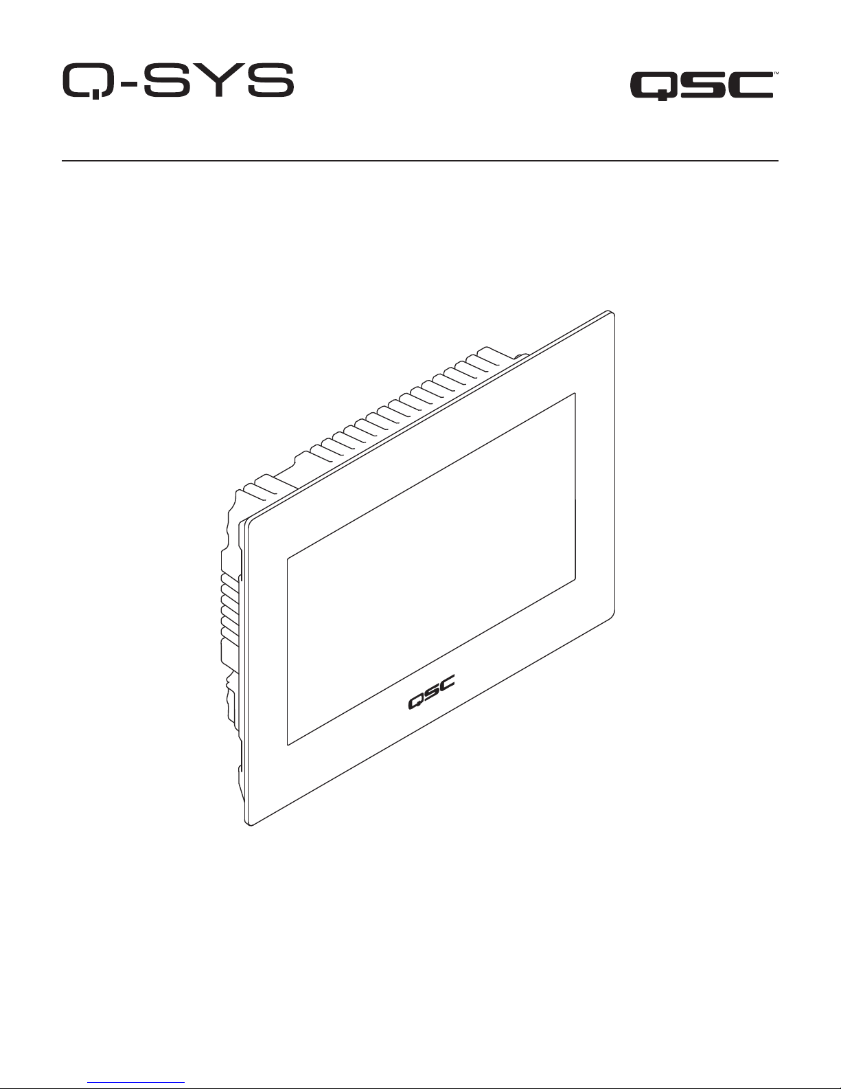
TSC-7w – Networked, Wall Mounted, 7" Touchscreen Controller
TD-000485-01 -A
*TD-000485-01 *
Page 2

EXPLANATION OF SYMBOLS
The term “WARNING!” indicates instructions regarding personal safety. If the instructions are not followed the result may be bodily injury or death.
The term “CAUTION!” indicates instructions regarding possible damage to physical equipment. If these instructions are not followed, it may result in
damage to the equipment that may not be covered under the warranty.
The term “IMPORTANT!” indicates instructions or information that are vital to the successful completion of the procedure.
The term "NOTE" is used to indicate additional useful information.
The intent of the lightning fl ash with arrowhead symbol in a triangle is to alert the user to the presence of un-insulated "dangerous"
voltage within the product's enclosure that may be of suffi cient magnitude to constitute a risk of electric shock to humans.
The intent of the exclamation point within an equilateral triangle is to alert the user to the presence of important safety, and operating
and maintenance instructions in this manual.
IMPORTANT SAFETY INSTRUCTIONS
WARNING!: TO PREVENT FIRE OR ELECTRIC SHOCK, DO NOT EXPOSE THIS EQUIPMENT TO RAIN OR MOISTURE.
1. Read these instructions.
2. Keep these instructions.
3. Heed all warnings.
4. Follow all instructions.
5. Do not use this apparatus near water.
6. Do not submerge the apparatus in water or liquids.
7. Do not use any aerosol spray, cleaner, disinfectant or fumigant on, near, or into the apparatus.
8. Clean only with a dry cloth.
9. Do not block any ventilation opening. Install in accordance with the manufacturer's instructions.
10. Keep ventilation opening free of dust or other matter.
11. Do not install near any heat sources such as radiators, heat registers, stoves, or other apparatus (including amplifi ers) that produce heat.
12. Do not unplug the unit by pulling on the cord, use the plug.
13. Only use attachments/accessories specifi ed by the manufacturer.
14. Unplug this apparatus during lightning storms or when unused for long periods of time.
15. Refer all servicing to qualifi ed service personnel. Servicing is required when the apparatus has been damaged in any way, such as power-supply
cord or plug is damaged, liquid has been spilled or objects have fallen into the apparatus, the apparatus has been exposed to rain or moisture,
does not operate normally, or has been dropped.
16. Adhere to all applicable, local codes.
17. Consult a licensed, professional engineer when any doubt or questions arise regarding a physical equipment installation.
TD-000485 -01 -A
2
Page 3
Maintenance and Repair
WARNING!: Advanced technology, e.g., the use of modern materials and powerful electronics, requires specially adapted
maintenance and repair methods. To avoid a danger of subsequent damage to the apparatus, injuries to persons and/or the
creation of additional safety hazards, all maintenance or repair work on the apparatus should be performed only by a QSC
authorized service station or an authorized QSC International Distributor. QSC is not responsible for any injury, harm or related
damages arising from any failure of the customer, owner or user of the apparatus to facilitate those repairs.
FCC Statement
NOTE: This equipment has been tested and found to comply with the limits for a Class B digital device, pursuant to Part 15 of the
FCC Rules.
These limits are designed to provide reasonable protection against harmful interference in a residential installation. This equipment generates, uses
and can radiate radio frequency energy and, if not installed and used in accordance with the instructions, may cause harmful interference to radio
communications. However, there is no guarantee that interference will not occur in a particular installation. If this equipment does cause harmful
interference to radio or television reception, which can be determined by turning the equipment off and on, the user is encouraged to try to correct
the interference by one or more of the following measures:
• Reorient or relocate the receiving antenna.
• Increase the separation between the equipment and receiver.
• Connect the equipment into an outlet on a circuit different from that to which the receiver is connected.
• Consult the dealer or an experienced radio/TV technician for help.
RoHS STATEMENT
The Q-Sys TSC-7w product is in compliance with European Directive 2011/65/EU– Restriction of Hazardous Substances (RoHS2).
The Q-Sys TSC-7w product is in compliance with “China RoHS” directives. The following chart is provided for product use in China and its territories:
Q-Sys TSC-7t
部件名称
(Part Name)
铅
(Pb)
电路板组件
(PCB Assemblies)
机壳装配件
(Chassis Assemblies)
本表格依据 SJ/T 11364 的规定编制。
O: 表示该有害物质在该部件所有均质材料中的含量均在 GB/T 26572 规定的限量要求以下。
X: 表示该有害物质至少在该部件的某一均质材料中的含量超出 GB/T 26572 规定的限量要求。
(目前由于技术或经济的原因暂时无法实现替代或减量化。)
This table is prepared following the requirement of SJ/T 11364.
O: Indicates that the concentration of the substance in all homogeneous materials of the part is below the relevant
threshold specifi ed in GB/T 26572.
X: Indicates that the concentration of the substance in at least one of all homogeneous materials of the part is above the
relevant threshold specifi ed in GB/T 26572.
(Replacement and reduction of content cannot be achieved currently because of the technical or economic reason.)
XOO O O O
XOO O O O
汞
(Hg)
有害物质
(Hazardous Substances)
镉
(Cd)
六价铬
(Cr(vi))
多溴联苯
(PBB)
多溴二苯醚
(PBDE)
Warranty
For a copy of the QSC Limited Warranty, visit the QSC Audio Products website at www.qsc.com
3
TD-000485 -01 -A
Page 4
Introduction
The Q-Sys TSC-7w series touchscreen controller provides remote management services for a Q-Sys audio system. The functionality of the TSC-7w
touchscreen controller is defi ned and confi gured by the system designer using Q-Sys Designer. You can download Q-Sys Designer Software from the
QSC Website www.qsc.com
Refer to the Q-Sys Designer on line help for setup and operation.
TSC-7w Features
The TSC-7w series products are network enabled, projective-capacitive touchscreen, control panels. The TSC-7w products are designed to connect to
a Q-Sys system via Q-LAN or to an auxiliary network to which the system Core Processor(s) is connected. The TSC-7w does not provide low latency
uncompressed audio services, allowing the TSC-7w to join a Q-LAN network via standard 10/100/1000 Mbps Ethernet connections.
The TSC-7w uses a color graphics display with a 400 nit anti-glare LCD. The control surface is a capacitive touch interface that is reliable, bright, and
easy to use.
The TSC-7w can be mounted in a wall (new or existing construction) or podium.
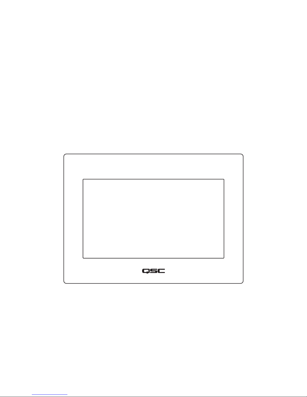
TSC-7w Front Panel Features
1. Capacitive-touch control surface and LCD viewing area (7" diagonal)
TD-000485 -01 -A
— Figure 1 —
4
Page 5

TSC-7w Rear Panel and Connector Edge Features
LAN A/PoE LAN B USB 12V DC
1
23 4
1. Mounting-hook slots (4 places)
2. Mounting screws (secures unit to the mounting ring)
3. Q-Sys LAN A with PoE (RJ45)
4. Q-Sys LAN B (redundant) (RJ45)
5. USB 2.0 Micro-AB OTG interface
5
6
— Figure 2 —
6. 12V DC AUX Power input (power supply not included)
7. Unit Reset button
8. Built-in Speaker
9. Screw holes (4 places - future use)
+
RESET
7
8
2
9
5
TD-000485 -01 -A
Page 6

TSC-7w Mounting Ring Features
7
6
12 3 4 5
— Figure 3 —
1. Retaining Clips (4)
2. Flip Clamps (4)
3. Outside Flange (4)
4. Touchscreen Securing Screw Holes (2)
5. Flip Clamp Screws (4)
6. Mounting Ring
7. Mounting Ring Hooks
Touchscreen TSC-7w Packing List
1. Q-Sys TSC-7w Touchscreen Controller
2. Hardware Installation Guide TD-000485
3. Installation Template
4. Warranty Statement TD-000453
TD-000485 -01 -A
5. Mounting Ring Assembly (1) – The assembly includes:
a. Flip Clamps (4)
b. Flip-Clamp Screws (4)
c. Flip-Clamp Snap-ring Retainers (4)
d. Unit-to-Bracket Securing Screws (2)
6
Page 7

Installation
The Q-Sys TSC-7w is designed to be mounted in a wall, or podium/desk, and so on. When you are mounting the unit in a wall, there are two options,
mounting the unit during construction of the wall, or mounting into an existing wall. The following instructions cover both installation options.
General Requirements
The TSC-7w
• Must have access to the Q-LAN Ethernet.
• Must be mounted with suffi cient space for adequate ventilation.
• Should not be mounted in a location where the TSC-7w may be an obstruction, for example, in a walkway or other traffi c areas.
• Mounting surface Thickness:
• Maximum – 1 1/4” (31.5 mm),
• Minimum – 1/2” (12.7 mm)
Power Source
• PoE (Power over Ethernet – IEEE 802.3af class 3 device) LAN A only
• 12V DC AUX Power source (not supplied)
◦ 12V DC @ 1A (12W)
◦ Barrel connector:
» Negative contact – 5.5mm +/- 0.2mm
» Positive contact – 2.5mm +/- 0.2mm
» Length - 9.5mm +/- 0.3mm
7
TD-000485 -01 -A
Page 8

Mounting the TSC-7w in a Wall or Podium
This procedure covers installing the Mounting Ring in
an existing wall or podium.
CAUTION!: Before cutting the
mounting hole, make sure that there is
nothing behind the wall/podium that can
be damaged during the cutting operation.
Ensure that there is enough space
surrounding the unit to provide
adequate ventilation.
NOTE: Be sure the touchscreen is
mounted where the Q-LAN network is
available.
Refer to Figure 4
Install the Mounting Ring
1. Determine the location where the hole for the
TSC-7w is to be cut.
12
IMPORTANT!: Leave a minimum of
1 inch clearance on all sides of the
opening to allow for mounting and the
TSC-7w touchscreen.
2. Use the Installation Template (included) to cut a 156.4 mm (6.2”) wide, by 113 mm (4.5 “) high rectangular hole in the mounting surface. The
opening must be in the landscape orientation (long side is horizontal), as shown in Figure 4.
NOTE: The following steps cover hardware already assembled on the Mounting Ring. They are included for cases where you may
need to re-install the hardware.
3. Install one Bracket Clamp screw (3) through each of the four Bracket Clamp Tabs (4).
4. Install one Clamp (2) on each of the four screws (3).
5. Install one Retaining Clip (1) on each of the four screws (3).
NOTE: The Retaining Clip is to help prevent the Clamp from dropping into the wall if the Screw is unscrewed to far.
— Figure 4 —
34
5
6. Turn the Bracket so the Bracket Mounting Hooks (5) are pointing up.
7. Turn the Clamps (2) so they are pointing towards the center of the Bracket.
8. Slide the Bracket assembly into the hole until the fl anges are up against the wall.
9. Turn the Clamps (2) so they are pointing away from the center of the Bracket.
10. Tighten the Mounting Bracket Screws (3) until the Clamps (2) make contact with the inside of the wall.
11. If necessary, adjust the Mounting Bracket to level. Tighten the Mounting Bracket Screws (3) to secure the Bracket in the wall. Do not over tighten.
TD-000485 -01 -A
8
Page 9

Connections
Refer to Figure 5
1. Feed the cables through the opening in the wall/bracket.
+
LAN A/PoE LAN B USB 12V DC
RESET
2. Connect the LAN-A with PoE RJ-45 connector to the LAN-A/PoE socket
back of the TSC-7w.
3. Optional – Connect the LAN-B RJ-45 connector to the LAN-B socket (2) on the
back of the TSC-7w.
4. If you are using an external power source, connect the barrel connector to the
TSC-7w 12V DC AUX Power input connector (4).
(1) on the
Mount the TSC-7w to the Mounting Bracket
Refer to Figure 6
1. Align the mounting slots (1) on the TSC-7w with the
mounting hooks (2) and carefully slide the TSC-7w into the
Mounting Bracket. Make sure the cables are not pinched or
stressed.
2. When the TSC-7w is in the mounting bracket, gently press
down to engage the hooks with the slots. Make sure all four
hooks are properly engaged.
3. Secure the TSC-7w to the mounting bracket with two screws
(3).
IMPORTANT!: Before you can use the
TSC-7w, you must confi gure the Q-Sys design
using Q-Sys Designer. Refer to the Q-Sys
Designer on-line help for details.
123 4
— Figure 5 —
— Figure 6 —
1332
9
TD-000485 -01 -A
Page 10

TSC-7w Dimensions
154 mm
6.1 in.
1 in.
26 mm
1.5 in.
38 mm
198 mm
7.8 in.
4.2 in.
107 mm
5.6 in.
143 mm
TD-000485 -01 -A
10
Page 11

TSC-7w Specifi cations
Specifi cation Value
Display
LCD Touchscreen 7” Projected Capacitive Touch (dual coordinate simultaneous touch sensitivity)
Luminance: 400 nits (400 lumen/candela per square meter)
Resolution: 800x400
Rear Panel Control Reset Button (Use a paper clip or similar tool to reboot the unit)
Power
PoE (Power over Ethernet) IEEE 802.3af class 3 device via LAN A
Optional External Source (not included) 12V DC AUX Power source (not supplied)
12V DC @ 1A (12W)
Barrel connector:
Negative contact – 5.5mm +/- 0.2mm
Positive contact – 2.5mm +/- 0.2mm
Length - 9.5mm +/- 0.3mm
Rear Panel Connectors
RJ45 (x2) LAN A (PoE) and LAN B ports (10/100/1000 Mbps)
USB type A port USB 2.0 Micro-AB OTG
Barrel connector: Power input Accommodates 12V DC AUX Power supply
Operating temperature range 0C to 50C
Dimensions (HWD) 5.6" x 7.8" x 1.5" (143 mm x 198 mm x 38 mm)
Weight
Net 1.4 lbs. (.64 kg)
Shipping 2.2 lbs. (1 kg)
Environmental
BTUs 40 max, 23 typical
Humidity 90% rh, non-condensing
Vibration 20 Grms
11
TD-000485 -01 -A
Page 12

Mailing Address:
Q-SYS 24/7 Emergency Support*
QSC Audio Products, LLC
1675 MacArthur Boulevard
Costa Mesa, CA 92626-1468 U.S.
Main Number: (714) 754-6175
World Wide Web: www.qsc.com
Tel: +1-888-252-4836 (U.S./Canada)
Tel: +1-949-791-7722 (non-U.S.)
*Q-SYS 24/7 Support is for Emergency assistance with Q-SYS systems
only. 24/7 support guarantees a call back within 30 min after a message
is left. Please include, Name, Company, Call Back Number and
description of the Q-SYS emergency for prompt call back. If calling during
business hours please use the standard support numbers above.
Q-Sys™ Customer Support
Sales & Marketing:
Voice: (714) 957-7100 or toll free (U.S. only) (800) 854-4079
FAX: (714) 754-6174
E-mail: info@qscaudio.com
Q-SYS Support Email
qsyssupport@qsc.com
(Immediate email response times not guaranteed)
Q-SYS™ Customer Support
Application Engineering and Technical Services
Monday - Friday 7 AM to 5 PM PST (Excludes Holidays)
Tel. 800-772-2834 (U.S. only)
Tel. +1 (714) 957-7150
QSC Audio Products
Technical Services
1675 MacArthur Blvd.
Costa Mesa, CA 92626 U.S.
Tel: 800-772-2834 (U.S. only)
Tel: +1 (714) 957-7150
© 2014 QSC Audio Products, LLC. All rights reserved. QSC, the QSC logo, Q-Sys, the Q-Sys logo, and Q-LAN are trademarks of QSC Audio Products, LLC in the U.S. and other
countries. All other trademarks are the property of their respective owners.
http://patents.qsc.com.
FAX: +1 (714) 754-6173
TD-000485 -01 -A
12
 Loading...