

Page 1
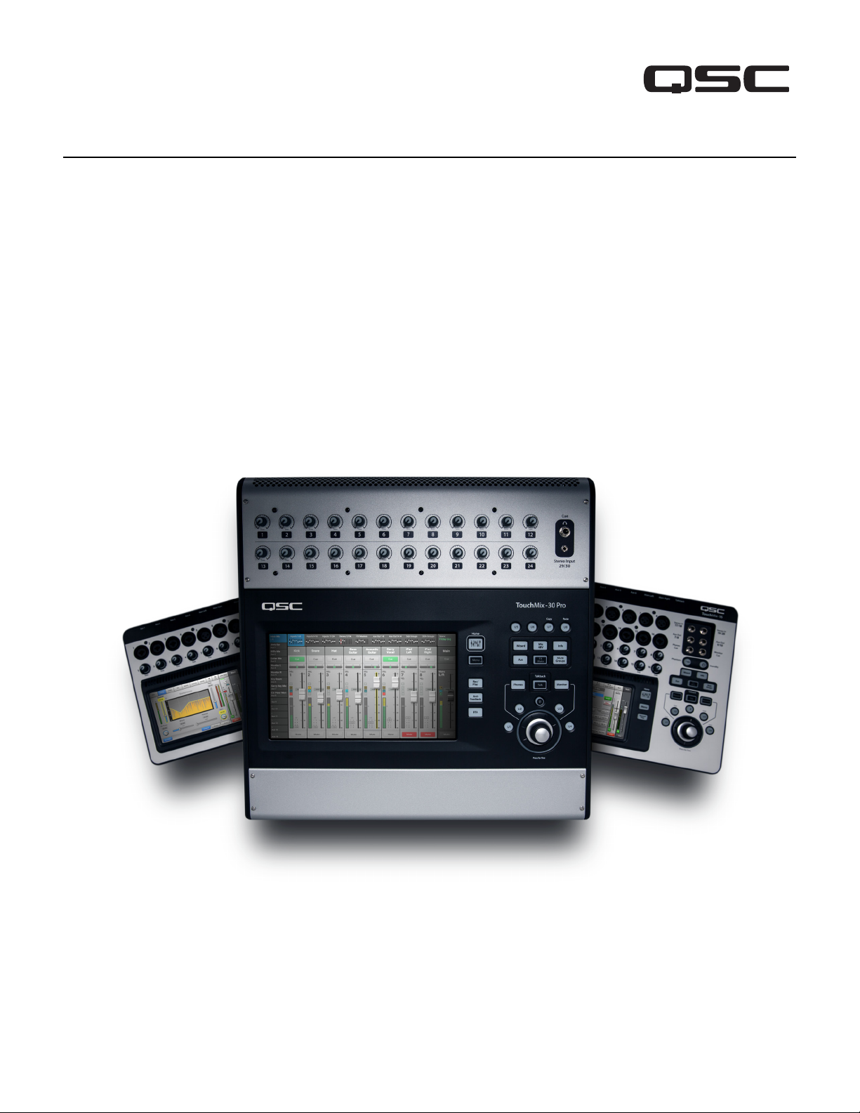
TouchMix®
®
User Manual
TouchMix-30 Pro Firmware Version 3.0
TouchMix-16 Firmware Version 3.0
TouchMix-8 Firmware Version 3.0
1001108-01-H
*1001108-01*
Page 2
EXPLANATION OF TERMS AND SYMBOLS
The term “WARNING!” indicates instructions regarding personal safety. If the instructions are not followed the result may be bodily injury or death.
The term “CAUTION!” indicates instructions regarding possible damage to physical equipment. If these instructions are not followed, it may result in
damage to the equipment that may not be covered under the warranty.
The term “IMPORTANT!” indicates instructions or information that are vital to the successful completion of theprocedure.
The term "NOTE" is used to indicate additional useful information.
The intent of the lightning flash with arrowhead symbol in a triangle is to alert the user to the presence of un-insulated "dangerous"
voltage within the product's enclosure that may be of sufficient magnitude to constitute a risk of electric shock to humans.
The intent of the exclamation point within an equilateral triangle is to alert the user to the presence of important safety, and operating
and maintenance instructions in this manual.
IMPORTANT SAFETY INSTRUCTIONS
WARNING!:
Maximum ambient operating temperature is 40°C (104°F).
WARNING!:
the power supply from the electric outlet immediately after use.
1. Read these instructions.
2. Keep these instructions.
3. Heed all warnings.
4. Follow all instructions.
5. Do not use this apparatus near water.
6. Do not submerge the apparatus in water or liquids.
7. Do not use any aerosol spray, cleaner, disinfectant or fumigant on, near or into the apparatus.
8. Clean only with a dry cloth.
9. Do not block any ventilation opening. Install in accordance with the manufacturer's instructions.
10. Keep all ventilation openings free of dust or other matter.
11. Do not install near any heat sources such as radiators, heat registers, stoves, or other apparatus (including amplifiers) that produce heat.
12. To reduce the risk of electrical shock, the power cord shall be connected to a mains socket outlet with a protective earthing connection.
13. Do not defeat the safety purpose of the polarized or grounding-type plug. A polarized plug has two blades with one wider than the other. A
grounding type plug has two blades and a third grounding prong. The wide blade or the third prong are provided for your safety. If the provided
plug does not fit into your outlet, consult an electrician for replacement of the obsolete outlet.
14. Protect the power cord from being walked on or pinched particularly at plugs, convenience receptacles, and the point where they exit from
theapparatus.
15. Do not unplug the unit by pulling on the cord, use the plug.
16. Only use attachments/accessories specified by the manufacturer.
17. Unplug this apparatus during lightning storms or when unused for long periods of time.
18. Refer all servicing to qualified service personnel. Servicing is required when the apparatus has been damaged in any way, such as power-supply
cord or plug is damaged, liquid has been spilled or objects have fallen into the apparatus, the apparatus has been exposed to rain or moisture,
does not operate normally, or has been dropped.
19. The appliance coupler, or the AC Mains plug, is the AC mains disconnect device and shall remain readily accessible after installation.
20. Adhere to all applicable, local codes.
21. Consult a licensed, professional engineer when any doubt or questions arise regarding a physical equipment installation.
22. Inspect the apparatus, including the power supply for signs of external wear and tear or signs of damage. All damage to the apparatus should
be immediately repaired by a QSC authorized service station or QSC International Distributor. Failure to perform necessary repairs could lead
to additional damage or to safety hazards. Failure to perform necessary repairs voids the limited warranty and QSC is not responsible for any
injury, harm or related damages arising from any failure to perform those repairs.
TO PREVENT FIRE OR ELECTRIC SHOCK, DO NOT EXPOSE THIS EQUIPMENT TO RAIN OR MOISTURE.
DO NOT LEAVE THE TouchMix-8 / TouchMix-16 POWER SUPPLY UNATTENDED WHEN PLUGGED IN. Always unplug
ii
Page 3

Maintenance and Repair
WARNING!:
and repair methods. To avoid a danger of subsequent damage to the apparatus, injuries to persons and/or the creation of additional
safety hazards, all maintenance or repair work on the apparatus should be performed only by a QSC authorized service station or an
authorized QSC International Distributor. QSC is not responsible for any injury, harm or related damages arising from any failure of the
customer, owner or user of the apparatus to facilitate those repairs.
Advance technology, e.g., the use of modern materials and powerful electronics, requires specially adapted maintenance
FCC Statement
NOTE:
FCCRules.
These limits are designed to provide reasonable protection against harmful interference in a residential installation. This equipment generates, uses
and can radiate radio frequency energy and, if not installed and used in accordance with the instructions, may cause harmful interference to radio
communications. However, there is no guarantee that interference will not occur in a particular installation. If this equipment does cause harmful
interference to radio or television reception, which can be determined by turning the equipment off and on, the user is encouraged to try to correct
the interference by one or more of the following measures:
• Reorient or relocate the receiving antenna.
• Increase the separation between the equipment and receiver.
• Connect the equipment into an outlet on a circuit different from that to which the receiver is connected.
• Consult the dealer or an experienced radio/TV technician for help.
This equipment has been tested and found to comply with the limits for a Class B digital device, pursuant to Part 15 of the
Warranty
For a copy of the QSC Limited Warranty, visit the QSC website at www.qsc.com
Para una copia de la Garantía Limitada de QSC, visite el sitio web de QSC, en www.qsc.com
Pour obtenir une copie de la garantie limitée de QSC, visitez le site de QSC à www.qsc.com
Besuchen Sie die Webseite von QSC (www.qsc.com) um eine Kopie der beschräenkte Garantie von QSC zu erhalten.
如果您想要QSC有限保修的複印本,请造访QSC品的网站www.qsc.com
Для ознакомления с условиями ограниченной гарантии, посетите страницу компании QSC в интернете www.qsc.com
www.qsc.comQSCQSC
iii
Page 4

Table of Contents
Maintenance and Repair ...... ..... ..... ..... ..... ..... .. ..... ..... ..... ..... ..... ..... ..... .. ... .. .....
FCC Statement ...... .. ... .. ..... ..... ..... ..... ..... ..... .. ... .. ..... ..... ..... ..... ..... ..... .. ... .. ..
Warranty ... ..... .... ..... .... ..... ....... ....... ....... ....... ....... ....... ....... ..... .... ..... .... ..
TouchMix® How To.
..............................................................................1
Register and Update .....................................................................................1
TouchMix-30 Pro Package Contents .....................................................................1
TouchMix-8 / TouchMix-16 Package Contents ............................................................1
About This Manual ......................................................................................1
Getting Started .........................................................................................1
Turn off Demo Mode ....................................................................................1
Recall a Factory Scene ..................................................................................2
What is a Scene? ....................................................................................2
Build a Mix Using Factory Presets .........................................................................2
What is a Channel Preset? .............................................................................2
Auxiliary Outputs .......................................................................................3
What is an Auxiliary? ..................................................................................3
iii
iii
iii
Effects ..................................................................................................3
Name the Effects Channels (or Mixes) .....................................................................3
Using the FX Wizard ....................................................................................4
Using the Input Channel FX Tab ...........................................................................4
Pitch Correct ..........................................................................................4
Using Pitch Correct ..................................................................................5
Using the FX Channel Effect Tab ...........................................................................5
Using the FX Overview ..................................................................................5
Mute Groups ............................................................................................6
DCA Groups .............................................................................................6
Sub Groups (TouchMix-30 Pro only) .....................................................................7
Using Auxiliaries as Sub Groups (TouchMix-8 and 16 only) ...............................................8
Matrix Mixing ...........................................................................................8
Save Your Work as a Scene ..............................................................................9
Sound Check ............................................................................................9
Using TouchMix with QSC Amplifiers and Loudspeakers .......................................................9
Loudspeaker Gain and Preset Pop-up .....................................................................9
Select a QSC Loudspeaker Preset ......................................................................10
QSC GXD Amplifier Settings ...........................................................................10
Phantom Power (+48V) ................................................................................10
iv
Page 5

Work on Your Inputs ...................................................................................10
Simple and Advanced Mode .............................................................................11
Auxiliary (Stage Monitor) Mixes ..........................................................................11
Input by Input ......................................................................................11
Mix On Faders ......................................................................................11
Output Processing .....................................................................................11
Overview Tab .......................................................................................12
PEQ Tab ..........................................................................................12
GEQ Tab ..........................................................................................12
Anti-Feedback Tab ...................................................................................13
Limiter Tab ........................................................................................13
Auxes Tab (TouchMix-30 Pro only) ......................................................................13
Presets Tab ........................................................................................13
Setup Tab .........................................................................................13
Recording ............................................................................................14
Multi-Track Playback & Mix Down .......................................................................16
Mix Down .........................................................................................16
DAW Interface. . . . . . . . . . . . . . . . . . . . . . . . . . . . . . . . . . . . . . . . . . . . . . . . . . . . . . . . . . . . . . . . . . . . . . . . . . . . . . . . . . . . . .16
Anti-Feedback System ..................................................................................17
Manually Ringing Out a System ..........................................................................17
Using the Feedback Wizard .............................................................................17
Pre-Feedback Wizard Checklist: ........................................................................17
More about the Anti-Feedback System ...................................................................18
Real Time Analyzer (RTA) ...............................................................................18
Mutes ..................................................................................................19
Copy & Paste ...........................................................................................20
Patch Matrix (TouchMix-30 Pro only) ...................................................................21
Room Tuning Wizard ....................................................................................22
TouchMix-30 Pro .....................................................................................22
TouchMix-8 or TouchMix-16 ............................................................................22
User Buttons ... ..... .. ... .. ..... ..... ..... ..... ..... ..... ..... .. ... .. ..... ..... ..... ..... ..... ..... .. .
MIDI Control ..... ..... ..... ..... ..... ..... .. ... .. ..... ..... ..... ..... ..... ..... ..... .. ... .. ..... ..... .
Security ...... .. ... .. ..... ..... ..... ..... ..... ..... .. ... .. ..... ..... ..... ..... ..... ..... .. ... .. ..... ...
.24
.24
.25
Monitor (TouchMix-30 Pro only) ... ..... .. ... .. ..... ..... ..... ..... ..... ..... .. ... .. ..... ..... ..... ....
Monitor (TouchMix-16 only) .. ..... .. ... .. ..... ..... ..... ..... ..... ..... ..... .. ..... ..... ..... ..... ....
Solo In Place (SIP) (TouchMix-30 Pro only) .
.............................................................26
v
.26
.26
Page 6

TouchMix Reference ............................................................................27
Getting Started ........................................................................................27
Top Panel and Remote-Device Controls (TouchMix-30 Pro) ..................................................27
Rear Panel (TouchMix-30 Pro) ...........................................................................28
Right Side of the TouchMix-16
Mixing Surface
Right Side of the TouchMix-8
Mixing Surface
Rear Panel (TouchMix-16) ..............................................................................32
Rear Panel (TouchMix-8) ...............................................................................32
TouchMix-30 Pro Specifications .........................................................................33
TouchMix-8 and TouchMix-16 Specifications ...............................................................35
TouchMix™ Feature List ................................................................................37
Nav Strip ..............................................................................................39
Channel Controls .....................................................................................40
Input Channels .........................................................................................41
Input Channel − Overview ...............................................................................41
Input Channel – Analog Trim .............................................................................43
........................................................................................30
........................................................................................31
Input Channel − EQ ....................................................................................44
Input Channel − Compressor ............................................................................45
Input Channel − Gate ...................................................................................46
Input Channel − FX Sends ...............................................................................47
FX Signal Flow ......................................................................................47
Input Channel − Aux Sends ..............................................................................48
Auxiliary Channels Flow Diagram ........................................................................48
Input Channel − Presets ................................................................................49
Input Channel − Setup ..................................................................................50
Output Channels .......................................................................................51
Output Channel – Overview .............................................................................51
Output Channel − GEQ .................................................................................52
Output Channel − PEQ ..................................................................................53
Output Channel − Compressor / Limiter ...................................................................54
Output Channel − Anti-Feedback .........................................................................55
Output Channel − Auxes
(TouchMix-30 Pro only)
Output Channel − Presets ..............................................................................57
Output Channel − Setup / Delay ..........................................................................58
Output – Speaker Settings ..............................................................................59
GXD Amp Settings ................................................................................59
On the GXD Amplifier ................................................................................59
On the TouchMix ....................................................................................59
Aux Overview .........................................................................................60
.................................................................................56
vi
Page 7

Sub Groups (TouchMix-30 Pro only) ....................................................................61
Sub Group − Overview ..................................................................................61
Sub Group − PEQ ......................................................................................62
Sub Group − Compressor / Limiter .......................................................................63
Sub Groups − FX Sends ................................................................................64
Sub Group − Auxes ....................................................................................65
Sub Group − Presets ...................................................................................66
Sub Group − Setup ....................................................................................67
2-Trk Playback ..........................................................................................68
2-Trk Playback − Overview ..............................................................................68
2-Trk PB – EQ .........................................................................................69
2-Trk Playback – Audio Player ............................................................................70
2-Trk Playback − Auxes .................................................................................71
2-Trk Playback − Presets ...............................................................................72
2-Trk Playback − Setup .................................................................................73
2-Trk / Multitrack Playback . . . . . . . . . . . . . . . . . . . . . . . . . . . . . . . . . . . . . . . . . . . . . . . . . . . . . . . . . . . . . . . . . . . . . . . . . . . . . 74
FX Masters .............................................................................................75
FX Master − Overview ..................................................................................75
FX Masters − EQ ......................................................................................76
FX Masters − Presets ..................................................................................77
FX Master − Setup ....................................................................................78
FX Master − Auxes ....................................................................................79
FX Overview ..........................................................................................80
Wizards ................................................................................................81
FX Wizard ............................................................................................81
Gain Wizard ..........................................................................................82
Room Tuning Wizard ...................................................................................83
FX Processor ...........................................................................................85
FX Processor – Basic Chorus. . . . . . . . . . . . . . . . . . . . . . . . . . . . . . . . . . . . . . . . . . . . . . . . . . . . . . . . . . . . . . . . . . . . . . . . . . . .85
FX Processor – Dense Reverb ...........................................................................86
FX Processor – Lush Reverb ............................................................................87
FX Processor – Mono and Stereo Delay ...................................................................88
FX Processor – Pitch Shift .............................................................................89
FX Processor – Pitch Correct ..........................................................................90
Remote Connections ..................................................................................91
Security ................................................................................................92
Login Screen ..........................................................................................92
Security Setup ........................................................................................92
vii
Page 8

Miscellaneous Features .................................................................................93
Menu ................................................................................................93
Remote Control Settings ...............................................................................94
User Buttons .........................................................................................95
User button defaults: ................................................................................95
Mixer Setup ..........................................................................................96
Phantom Power .......................................................................................97
Mute Groups ...........................................................................................98
About Mute Groups ....................................................................................98
Mute Groups Screen ...................................................................................98
Mute Group Edit Screen ...............................................................................98
Record / Playback (Multitrack USB Drive) .................................................................99
Record / Playback – Main Screen .......................................................................99
2-Trk − Recording ....................................................................................100
2-Trk Recording Setup ..............................................................................100
DAW – Record / Playback (TouchMix-30 Pro only) .........................................................101
Real-time Analyzer (RTA) ...............................................................................102
Scenes ............................................................................................103
Channel Safe .........................................................................................104
Auto Mixer TouchMix-30 Pro ..........................................................................105
Description .......................................................................................105
Accessing the Auto-Mixer ............................................................................105
Auto-Mixer Controls and Indicators ....................................................................105
External Control Surfaces - TouchMix-30 Pro ............................................................106
Channel Strip View ................................................................................106
Custom Fader Banks - TouchMix-30 Pro .................................................................107
Set up the Custom Fader Banks .......................................................................107
DCA Group Assignments ..............................................................................108
About DCA Groups .................................................................................108
MIDI ................................................................................................109
Talkback / Noise ......................................................................................110
TouchMix Wi-Fi Control ................................................................................111
Before You Begin .....................................................................................111
Wi-Fi Router Access Point .............................................................................111
Setting it up ......................................................................................111
Connecting to a Facility’s Network .....................................................................111
Wireless Network Setup: Create New Network ...........................................................112
Wireless Network Setup: Connect to Existing Network .....................................................113
Wired Network Setup: Static IP Address ................................................................114
Wired Network Setup: Auto IP Address (DHCP) ..........................................................115
viii
Page 9

TouchMix-30 Pro Phones and Monitor ...................................................................116
Phones Level ......................................................................................116
Monitor Level and Settings ...........................................................................116
TouchMix-8 and TouchMix-16 Phones
and TouchMix-16 Monitor ............................................................................116
Aecording Setup – Multitrack USB ......................................................................117
Aecall Session – Multitrack USB ........................................................................118
Wux Mix on Faders ...................................................................................119
TouchMix-30 Pro ..................................................................................119
Summary ........................................................................................119
Control Descriptions: ...............................................................................119
Patch Matrix (TouchMix-30 Pro only) ....................................................................120
Using the Patch Matrix ..............................................................................120
Copy and Paste ......................................................................................121
TouchMix-30 Pro Firmware Version 3.0 Features ... ..... ..... ..... ..... ..... .. ..
Scenes, Snapshots and Cue Lists
Scenes
Snapshots
Cue Lists
.....
.....
. . . . . . . . . . . . . . . . . . . . . . . . . . . . . . . . . . . . . . . . . . . . . . . . . . . . . . . . . . . . . . . . . . . . . . . . . . . . . . .
.............
. . . . . . . . . . . . . . . . . . . . . . . . . . . . . . . . . . . . . . . . . . . . . . . . . . . . . . . . . . . . . . . . . . . . . . . . . . . . . . . .
.... .
......
.... ...
. . . . . . . . . . . . . . . . . . . . . . . . . . . . . . . . . . . . . . . . . . . . . . . . . . . . . . . . . . . . . . . .
.... .........
. . . . . . . . . . . . . . . . . . . . . . . . . . . . . . . . . . . . . . . . . . . . . . . . . . . . . . . .
.
TouchMix Dimensions ...... ..... ..... ..... ..... .. ... .. ..... ..... ..... ..... ..... ..... .. ... .. ..
TouchMix-30 Pro ... ..... ..... ..... ..... ..... ..... .. ... .. ..... ..... ..... ..... ..... ..... .. ... .. ..... ...
TouchMix-8 ... .. .. .. .. .. .. . .. .. .. .. .. .. .. .. .. .. .. .. .. .. .. . .. .. .. .. .. .. .. .. .. .. .. .. .. .. .. . .. .. .. .. .. .. .
TouchMix-16 .. ..... ..... ..... ..... .. ... .. ..... ..... ..... ..... ..... ..... .. ... .. ..... ..... ..... ..... ...
TouchMix Block Diagram ....... ..... ..... ..... ..... .. ... .. ..... ..... ..... ..... ..... ..... ....
Mic/Line Input Channels ...... ..... ..... ..... ..... ..... .. ... .. ..... ..... ..... ..... ..... ..... ..... .. ...
Stereo Input Channels ... ..... ..... ..... ..... ..... ..... ..... .. .... ..... ..... ..... ..... .. ..... ..... ....
Main Output ... ... .. ... ... ... .. ... ... ... ... .. ... ... ... .. ... ... ... ... .. ... ... ... .. ... ... ... .. ... ... ... .
Stereo Auxiliary Output ...... ..... ..... ..... ..... ..... .. ... .. ..... ..... ..... ..... ..... ..... .. ... .. ...
Mono Auxiliary Output ... .. . . .. . .. . .. . .. . .. . .. . .. . .. . .. . .. . .. . .. . .. . .. . .. . .. . .. . .. . .. . .. . .. . .. . . .. . .. .
Stereo Sub Group (TouchMix-30 only) .. ..... ..... .. ... .. ..... ..... ..... ..... ..... ..... ..... .. ... .. ...
Mono Sub Group (TouchMix-30 only) ..... ..... ..... ..... ..... .. ... .. ..... ..... ..... ..... ..... ..... .. .
Cue, Monitor, Talkback, Noise ...... .... ..... .... ..... .... ..... .... ..... .... ..... .... ..... .... ..... ....
FX Return .. ..... .. ... .. ..... ..... ..... ..... ..... ..... ..... .. ... .. ..... ..... ..... ..... ..... ..... .. ... .
2-Track Playback .. ..... ..... ..... ..... .. ... .. ..... ..... ..... ..... ..... ..... ..... .. ... .. ..... ..... ....
RTA (Real Time Analyzer) ..... ..... ..... ..... ..... ...... ..... .. ... .. ..... ..... ..... ..... ..... ..... ....
123
.
123
.
123
.
.
124
.
125
126
.
126
.
127
.
128
.
129
.
129
.
130
.
131
.
132
.
133
.
134
.
135
.
136
.
137
.
138
.
139
.
Contact QSC .... .. ..... ..... ..... ..... ..... ..... .. ... .. ..... ..... ..... ..... ..... ..... .. ... .. ....
ix
140
.
Page 10

TouchMix® How To
Mixer Setup
STOP
IMPORTANT:
Firmware Version 3.0 installed. Earlier firmware releases do not support all of the functions described and some operations may differ.
This User Manual applies to mixers with TouchMix-30 Pro Firmware Version 3.0, or TouchMix-8 and TouchMix-16
Register and Update
We know you want to get right to using your TouchMix mixer, but before you do please stop and take a moment to visit www.qsc.com and register
your TouchMix. By registering you can…
• Download the latest firmware so that your mixer has all the latest features, refinements and performance enhancements.
• Sign up to be notified of future updates.
• Check to see if you are eligible for free extended warranty coverage.
While you’re there, you can also find videos and other tools to help you get the most from your TouchMix-30 Pro.
TouchMix-30 Pro Package Contents
1. TouchMix-30 Pro Mixer
2. Quick Start Guide TouchMix-30 Pro (TD-000509)
3. Warning Information Sheet (TD-000430)
4. Limited Warranty (TD-000453-01 English)
5. One of the following power cords
6. North America TouchMix-30 Pro, 2M, V-Lock
7. Europe TouchMix-30 Pro, 2M, V-Lock
TouchMix-8 / TouchMix-16 Package Contents
1. TouchMix-16 or TouchMix-8
2. Quick-Start Guide (TD-000445 or TD-000446)
3. Warning Information Sheet
4. Limited Warranty (TD-000453-01 English)
5. USB Wi-Fi adaptor (installed in mixer’s USB port)
6. Power supply with IEC cable (AC connector type varies by region)
7. TouchMix carrying case
About This Manual
This manual covers the features and operation of the TouchMix-8, TouchMix-16 (with firmware version 3.0) and TouchMix-30 Pro (with software
version 2.0). These mixers share many features and operational similarities but differ in other respects – most significantly, input and output
channel count. Features and functions that are unique to just one model are identified as such.
Getting Started
Since your TouchMix is a digital mixer there are lots of things you can do off-line to save time during setup and help you get acquainted with your
mixer. We highly recommend spending a little quality time with the mixer before taking it to a show for the first time.
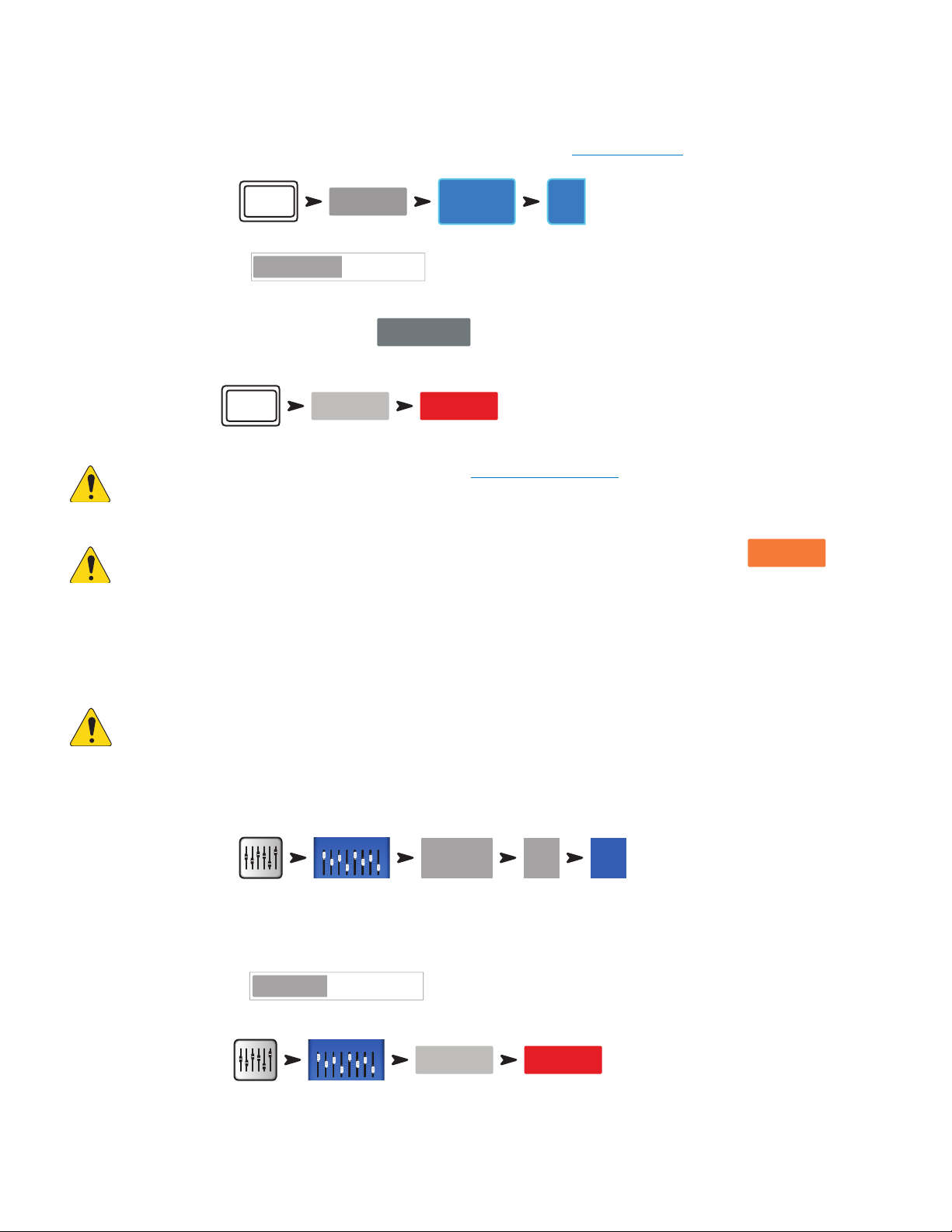
Turn off Demo Mode
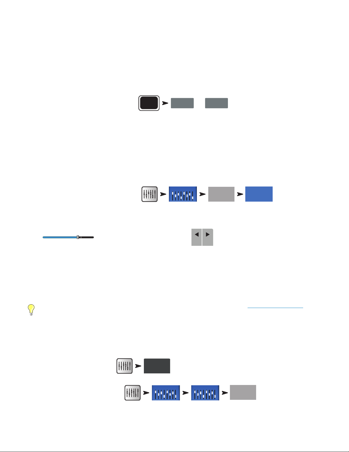
Demo mode is a looping slide show that plays as a factory default to give prospective buyers an overview of the mixer. You’ll probably want to turn
Demo Mode off – even though our graphics guys are really proud of how itlooks.
To Disable Demo Mode:
Menu
Demo Mode Off On
1
Page 11
Recall a Factory Scene
Rock Band
Rock Band
Inputs 1-8
Preset Name
Preset Name
Yes
What is a Scene?
Scenes allow storage and recall of mixer settings. A Scene includes all channel-processing settings, channel Names, Phantom Power settings,
Effects selections, DCA, Sub Group and Mute Group assignments. Scenes also include level settings. Factory scenes are stored with input faders at
minimum to prevent any surprises (feedback, music at 20 dB above the threshold of pain, etc.) when the scene is recalled. User scenes are stored
with levels set as they were when the scene was saved. User scenes may be stored to internal memory and to an external USB storage device.
There are circumstances when it’s useful to recall a scene but omit certain settings from being changed. The TouchMix-30 Pro offers these Recall
Options:
• Omit Levels: When switched on, the scene will be recalled without making any change to any level settings.
• Omit Outputs: When switched on, the scene will be recalled without making any change to any output EQ, comp/limiter or level settings. This is
especially useful when recalling a scene after the mixer’s outputs have been adjusted for a particular venue and speaker system.
• Omit Routing: When switched on, the scene will be recalled without making any change to routing such as Sub Group assignments and pre/
postselections.
Your TouchMix is loaded with pre-defined scenes for various kinds of performances. You can find the one that’s most like the show you’ll be mixing
and start there.
To Recall a Factory Scene:
Scene:
Default
Defualt
Horn Band
Factory
Recall
The factory scenes list includes a scene named Default. This scene will “zero” the mixer by returning all controls to their factory settings.
To Zero the mixer:
Scene:
Default
Defualt
Horn Band
Factory
Recall
If you'd like to navigate around the mix and see what the recalled settings are, return to the screen.
Build a Mix Using Factory Presets
What is a Channel Preset?
A Channel Preset consists of settings for a single channel that are saved and can be recalled for use at a later time. A Channel Preset includes
settings for the channel EQ, Compressor and Gate. The channel name, phantom power setting and level settings are also stored with the preset but
may be omitted from a preset recall by setting the Recall Options switches at the bottom of the presets screen.
Your TouchMix includes over 120 channel presets that were programmed to work with common microphones in real, live sound applications by
skilled and experienced concert-sound mix-engineers. And they work. Those who have used TouchMix-30 Pro report great results using the presets
with little or no modification. You can also save your own channel presets to the mixer’s internal memory or to an external USB storage device.
To Select Channel Presets:
In 1
Presets
1. Make sure that the Factory / User switch is in the Factory position.
2. In the left window you’ll see a list of instrument categories. Touch an instrument category name and a list of specific instruments appears in the
3. Select a type of instrument and the right window will display a list of options for that instrument. There may be options with and without gates
To Learn About the Selected Preset:
To Recall the Preset:
middle window.
and compressors as well as options for various types of microphones and pick-ups or different styles of music. Select the one that seems best
for yourapplication.
Preset Info
Select any item
Select any item
Recall
2
Page 12

You’ve just dialed in the settings for an input channel. You’ll also notice that the channel has been given a name that corresponds with the
Aux Masters
Aux Masters
FX Masters 1-8
instrument you selected. You can leave the name as is or rename the channel.
To Name a Channel:
Go to the Next Channel:
Repeat the process until you’ve set up all the channels you need.
Setup
Next
Joe’s MicMic
Enter
Auxiliary Outputs
What is an Auxiliary?
In addition to the Main L/R (left/right) output mix, your TouchMix mixer is capable of controlling 4 (TouchMix-8), 8 (TouchMix-16) or 14
(TouchMix-30 Pro) additional output mixes.
These Auxiliary mixes are typically used to drive stage monitor speaker systems or in-ear monitors (IEM) for performers. They may also be used
for a recording mix, audio feed to video or a send to an overflow area. In any case, it makes sense to label the auxiliary outputs to help keep them
straight during use. Type in a name for the output – it could be the name of the performer who gets that mix or it could be something like “Singers”
or “Horns” or “Video” or “Patio”.
To name an auxiliary output:
The name will be displayed on the aux mix selector buttons on the left side of the screen.
Auxes may also be linked so that two mono mixes become one stereo mix.
Aux 1
Setup
Aux
Joe’s Monitor
To Link two Auxes:
TouchMix-30 Pro
receive their signal from the corresponding Auxiliary Mixes and are intended to drive wired, In Ear Monitors (IEM). If using these outputs, it’s
recommended that the Auxiliary mixes driving these headphone outputs be linked for stereo operation.
TouchMix-8
TouchMix-16
outputs may also be configured as balanced, mono, line-level outputs (see the Aux output channel Setup tab).
– A pair of TRS headphone outputs labelled Aux 11/12 and Aux 13/14 may be found on the mixer’s rear panel. These outputs
– A single TRS headphone output labelled Aux 3/4 may be found on the mixer’s rear panel.
– A pair of TRS headphone outputs labelled Aux 7/8 and Aux 9/10 may be found on the mixer’s top panel. These unbalanced, stereo
Aux 1
Setup
Link Link
Effects
Audio effects (FX) such as reverb, delay, chorus, pitch shift (pitch change) and pitch correct are essential in today’s audio production.
The TouchMix-30 Pro has six multi-effects processors or “engines” while the TouchMix-8 and TouchMix-16 have four. All of these processors may
be configured to be one of six different effects including Lush Reverb, Dense Reverb, Chorus, Mono Delay, Stereo Delay and Pitch Shift.
Each of these effects have multiple presets. The reverb processors, for example have presets simulating various sizes of rooms and halls as well as
reverb plates. In addition, there are brighter and darker sounding variations.
Along with the above effects, there is a Pitch Correct effect that can be assigned (inserted) to any one of the input channels.
Name the Effects Channels (or Mixes)
In the middle of a show it’s easy to forget which effect was intended for what performers or instruments so this would be a great time to name the
Effects Send channels. For example, you might name an FX channel “Voc Delay” or “Drum Rev”.
To Name FX channels:
FX 1
3
Setup
FX
New Verb
Page 13
Using the FX Wizard
FX
Inputs 1-8
FX
Less experienced users will find that the FX Wizard simplifies what can be a confusing process while skilled operators will find it to be incredibly
fast. With the FX Wizard you can quickly…
• Select an effect that’s right for the instruments or voices you want to enhance.
• Bring the instruments or voices into the effect.
• Adjust the overall amount of the effect that will be heard.
• Send the effect to monitors as you desire.
Select and Assign Effects (FX) Using the Wizard:
Select an effect preset. Only effects that work for the Source and Type of input you have selected will be shown. So any effect you select using the
wizard will be a valid one although it may or may not work in the context of your mix
Select an Effect Preset:
1. Use the Master Encoder or touch-and-drag to scroll up and down the list to see all the selections. Select one item from each list.
2. Touch Recall. The Preset is now loaded, and the name is displayed below the Type window.
3. With the Preset loaded, it’s time to decide which input channels should go to the FX1 processor.
Send inputs to the FX processor:
4. Buttons with the names of inputs are displayed on the Wizard Screen. Touch any button to send an input to the effect. Use the FX Master fader
to adjust the amount of effect heard in the main mix.
Send the effect to monitors:
5. Is the performer going to want to hear the effect in the stage monitors or in-ear monitors? If so, it’s easy to send it there. Just use the "Select
Aux Outputs (monitors) to receive:" buttons to route the effect to a monitor.
6. There are more effects available so touch one of the tabs at the top of the screen to set up more effects.
Wizard
FX Wizard
FX 3
Using the Input Channel FX Tab
The FX tab on the Input Channels provides another way to select and control effects.
To access FX from an Input Channel:
In 1
Once in the Channel FX screen, you can…
• Go to the Effects Processor’s control panel by touching a control panel icon. Press Home to come back.
• Use the sliders to control the amount of signal sent from the channel to each of the Effects Processors,
• Adjust the two most important parameters for each Effect using the “Global FX Parameters” controls. Note that any adjustment made to these
controls is global and will change the Effect everywhere it is used.
Pitch Correct
To assign Pitch Correct to a channel:
The Pitch Correct Effect is somewhat different than the Reverb, Delay, Chorus and Pitch Shift Effects. Pitch Correct can only be used on one input
channel at a time and there is one Pitch Correct effect. When it is assigned to a channel, it will be unassigned from any channel to which it was
previously assigned.
Touch the Enable button to assign Pitch Correct to the currently selected channel.
In 1
4
Pitch Correct
Enable
Page 14
Using Pitch Correct
FX Masters 1-8
FX Masters 1-8
Yes
Use the Blend control to vary the mix between corrected (wet) and uncorrected (dry) signal. 100% wet is used to correct pitch. A blend between wet
and dry is used to provide a doubling effect.
Use the Key control to select a musical key. This helps Pitch Correct be more accurate in determining what the intended note is.
Use the Correct Rate control to adjust how quickly the pitch correction tracks.
Using the FX Channel Effect Tab
Go to the FX Channel Effect Tab (From the Input Channel FX tab):
To Access the FX Control Panel:
FX 1
Eect
Touch the Effect window to select the type of effect.
• Chorus
• Stereo Delay
• Pitch Shift
• Dense Reverb
• Lush Reverb
• Mono Delay
Once an Effect is selected touch the Preset Tab. From this screen select a preset setting for the effect. Note that the setting can include EQ. Factory
presets are displayed in the left-hand window. User presets may be stored and recalled using the center and right-hand windows.
Factory
Pitch-Light Detune
Pitch-Medium Detune
To select an Effects preset:
Recall
FX 1
Presets
Eect
Touch the Effect Tab to return to the Effect Processor control panel. Each type of Effect Processor displays a different control panel with parameters
appropriate for the Effect.
Use the FX Master fader to the right of the FX panel to adjust the amount of effect heard in the main speaker system.
To adjust the level of the Effect sent to the Main L/R Output:
Below the Effect control panel is the FX Returns to Monitors section. Use the sliders to set how much of the effect is sent to each auxiliary / monitor
mix. If two auxiliaries have been linked, a slider and a pan control will be displayed. Above each slider is a channel label and a Mute [M] indicator.
Using the FX Overview
If you would prefer to see the send and return levels for all your effects at once, the FX overview is the place to go.
To use the FX Overview:
Menu
1. Input channels are arranged in columns. Use the Nav Strip to select a group of Input channels. Each Input channel sends for FX Sends 1–4
(TouchMix-8 and TouchMix-16) and 1 – 6 (TouchMix-30 Pro).
2. Individual FX Mixes are arranged in horizontal rows.
3. FX Master fader – The FX Master fader controls the overall output level of the FX Mix to the Main L/R outputs. Note that the FX Master does not
affect the level of the Effect sent to the Aux channels.
4. Effect Processor – Indicates the type of Effect currently being applied to the FX Mix.
So that’s about it for effects. We worked hard on the TouchMix effects and know that they sound superb and will enhance your performances. You
can dive in deep or just use the wizards, factory defaults and presets. Either way, you now have the tools for a great sounding show.
FX Overview
5
Page 15
Mute Groups
Mute
Groups
Mute
Groups
DCA Groups
DCA 1
In 1
In 3
DCA Groups
Mute
There are many times when it is useful to mute some of the inputs and outputs. For example, you might want to mute everything but a stereo input
for break music. Or there may be a part of your show when the band leaves the stage while one member does a solo number. Mute groups let you
mute multiple inputs and outputs from a single button. For more information on mutes, see "Mutes" on page 19
To set up Mute Groups:
To name the Mute Group:
Mute Group Name
Edit
Mute Joe
New Verb
Select another Mute group to set up or touch
To use Mute Groups:
NOTE:
NOTE:
Mute Groups can be assigned to the User Buttons. "User Buttons" on page 24.
When a channel is muted by a Mute Group, the channel Mute button on the Home screen looks like:
Mute
DCA Groups
Close Edit
Mute
Mute 1
Close Edit to finish.
Select channels to be assigned
In 1
Mute
A DCA groups faders together so the overall level of all the channels in the group can be controlled by a single DCA fader.
A DCA fader does not change the position of any of the faders in the group.
IMPORTANT:
Here is an important thing to know – if the DCA master fader is at 0.0 (the unity (U) mark), it does nothing to the
level of an assigned channel. The DCA adds or subtracts level. Move the DCA Fader up 3 dB and everything it’s assigned to will
increase by 3 dB. Move it down 3 dB and – well you probably figured that out. Remember that assigning or unassigning a channel
to a DCA Group can cause a sudden change in the level of the channel so it’s good practice to have the DCA master at 0.0 when
changingassignments.
To Setup a DCA Group:
Continue selecting channels as you
wish.
You can assign inputs, outputs and FX Master faders to a DCA. If you assign an input, and the output to which it's going to the same DCA, changes
you make using the DCA are doubled for the input. Raise the DCA 3 dB, the input is effectively raised 6 dB.
To Name the DCA group:
To Mute a DCA Group:
FX
DCA Name
Drums
Mute
When you mute a DCA, all channels assigned to that DCA are muted. If a channel is muted by the channel Mute button, or a Mute Group, the DCA
does not un-mute the channel when the DCA is un-muted.
6
Page 16
Sub Groups (TouchMix-30 Pro only)
Sub Groups
Inputs 1-8
In 1
Setup
Sub Groups
Sub 1
Setup
In 1
Like DCA Groups, Sub Groups are used to control the volume of multiple channels at once. However, DCA Groups simply add or subtract gain for
the channels they control. No signal is routed through a DCA. Unlike DCA Groups, signal is routed through Sub Groups. This means that Sub Groups
can apply processing including EQ, Limiting and even Effects to multiple channels. There are basically three ways that Sub Groups are used…
• To apply common processing and level control to multiple inputs and return the processed group to the Main L/R mix.
• To route a group of inputs to an external destination such as a broadcast mix. These output groups are commonly referred to as “stems”.
• To route a blend of Sub Groups to an external destination.
All eight Sub Groups appear on the Auxiliary mixes.
To output Sub Groups:
Joe’s Vocal
Aux 1
There are two ways to assign Input Channels to Sub Groups.
From an Input Channel
To assign a channel to Sub Groups:
Sub 3
If the Sub Group is going to be sent to the Main L/R output, the channel should usually be unassigned from Main L/R. Otherwise the channel’s
signal will be sent directly to the Main L/R output (without any processing) and also sent to the Main L/R by way of the Sub Group. There are some
advanced use cases where such a double assignment may be desirable but typically that is not the case.
From a Sub Group
To assign channels to a Sub Group:
This will take you to the Sub Group Setup page.
The lower portion of the page displays the numbers and friendly names of the input channels. Touch the button of the channels you wish to assign
to the Sub Group. If the channel is assigned to the Main L/R mix, an [L/R] icon will appear by the button,
NOTE:
"Remove Input Channel from L/R when assigning to Sub Group?"
In the “Yes” position, assigning an input channel to a Sub Group will cause the input to be unassigned from the Main L/R.
In the “No” position, assigning a channel to a sub group will have no effect on the channel’s Main L/R assignment.
7
Page 17
Using Auxiliaries as Sub Groups (TouchMix-8 and 16 only)
Aux Masters
Aux 5
Setup
Main L/R
Inputs 1-8
Setup
Main L/R
Main Out
The Auxiliary mixes may be assigned to the Main L/R output allowing the auxiliaries to function as sub groups. This feature is intended for use with
the input channel “Assign To Main L/R” function.
To use an Auxiliary channel as a Sub Group (for this example, we are assigning In Channel 1 to Aux 5 Sub Group):
1.
2.
*Adjusting the Aux Send 5 to 0 adds the Input Channel 1 to the Sub Group.
3. Repeat Step 2 for all the input channels that are part of the Sub Group.
4. The channel faders Aux Master (Aux 5) now functions as a Sub Group Master.
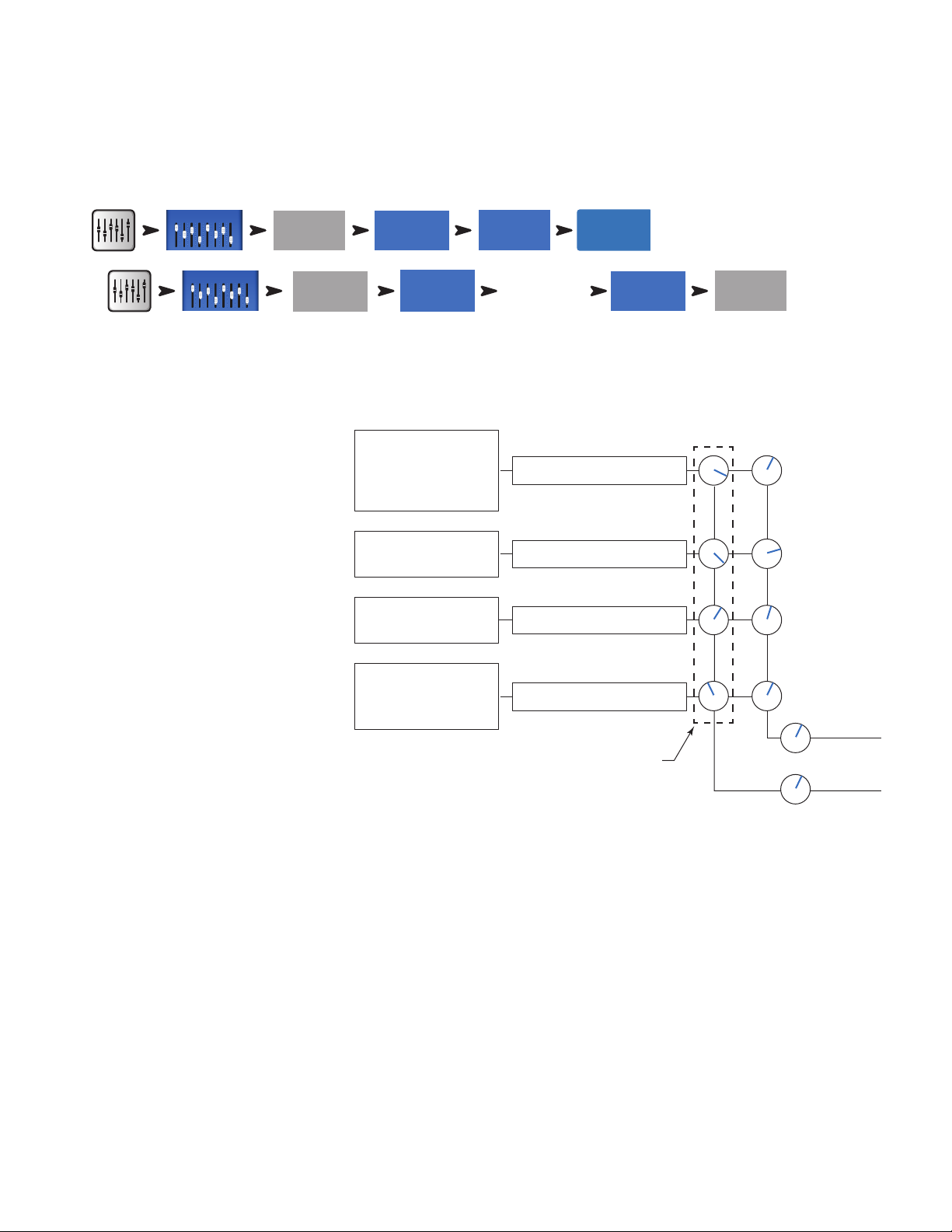
Matrix Mixing
To understand a matrix, it’s first useful
to understand the concept of a sub-mix
(sometimes called a “stem”). As the name
implies, a sub-mix is a mix consisting of some
subset of all the mixer’s inputs. For example
there could be sub-mixes consisting of all
the violins, or the choir, or drums, or delegate
microphones or sound effects. If you’ve got all
of these at once you’ve got a really interesting
production but we digress. A matrix simply lets
you blend these sub-mixes (stems) into a single
mix.
A stem can be created by assigning inputs to a
Sub-Group or by sending them to an Auxiliary.
Now that we’ve got the stems, what do we do
with them? On the TouchMix-30 Pro, Auxiliaries
9 – 14 also function as mix matrices. In addition
to all the input channels, these signals may be
sent to Auxiliaries 9 – 14…
• Main L/R
In 1
In 1 – Kick
In 2 – Snare
In 3 – Overhead
In 4 – Overhead
In 5 – Lead Guitar
In 6 – Rhythm Guitar
In 7 – Piano
In 6 – Organ
In 9 – Lead Vocal
In 10 – Backing 1
In 11 – Backing 2
Auxes
Adjust Aux
send 5 to 0*
Sub Group 1 – Drums
Sub Group 2 – Guitars
Sub Group 3 – Keyboards
Sub Group 4 – Vocals
Sub Groups’ Aux 1 Sends
Post Fader
Sub 1 Fader
Sub 1 Fader
Sub 1 Fader
Sub 1 Fader
Aux Out
• Auxiliaries 1 – 8
• Sub-Groups 1 – 8
All of these stems can be mixed as needed and routed out via Auxiliaries 9 – 14. The application may be as simple as just sending a mono mix of
the Main L/R to an overflow area or as complex as creating a separate broadcast mix from 8 or more stems. In addition, all the inputs are available
on Auxiliaries 9 – 14 so it’s possible to mix in the signal from one or more input channels.
8
Page 18

Save Your Work as a Scene
Save/Save As
Storage Location
Inputs 1-8
Inputs 9-16
Inputs 17-24
Stereo In/2-Trk
Aux Masters
Aux Out 9-14
Mute Mute
Mute Mute
Mute Mute
Mute Mute
Mute Mute
Mute Mute
Main
Setup
Aux Masters
Aux 1
Setup
You’ve put some effort into setting up your mix so now would be a great time to save it. A Scene is a snapshot of all the settings on the mixer.
TIP:
It's a good idea to save your scene with the outputs muted or levels down. Why? Because it's possible that the gain settings
on power amplifiers or powered loudspeakers have changed since the scene was saved. Recalling the scene could result in a blast of
feedback from all the speakers connected to the mixer.
To Save Your Scene:
To Name Your Scene:
To Save Your Scene:
Menu
Save Scene
As:
Mixer USB
Scenes
Saturday Night
Save
Sound Check
Before connecting anything, plug in your TouchMix and make sure that all the inputs and Auxiliary Outputs are muted. This will prevent uncontrolled
feedback if a microphone is patched into a hot channel.
To Mute Channels:
In each of the groups of faders, press the Mute button for each channel. Now you can connect the mixer to sources and speaker systems.
Using TouchMix with QSC Amplifiers and Loudspeakers
If you’re using QSC E, K,
K.2, KW
or
KLA
loudspeakers or
GXD
amplifiers your TouchMix can recommended input level
settings to help optimize your system gain structure as well as offering output presets for different applications.
For Main L/R:
For Aux outputs:
Select an amplifier or loudspeaker series.
Select an amplifier or loudspeaker series.
Loudspeaker Gain and Preset Pop-up
In addition to displaying the recommended input gain setting (1) for the selected
loudspeaker (2), the pop-up displays a choice of presets (3) for the loudspeaker. For
most QSC loudspeaker there are options that optimize the loudspeaker for live sound
reinforcement, stage monitor use or dance music playback.
In the pop-up all you need to do is:
1. Touch the button associated with your loudspeaker, or amplifier
2. Adjust your equipment as instructed
3. Select the preset you want to use with your loudspeakers
4. Touch Recall Preset.
Select QSC Speaker Model and Preset Name to display Gain Settings or Recall a Preset
Done
3
Preset NameModel
Dance
Floor Monitor
Live Bright
Live
Studio
Vocal Monitor
Recall Preset
K10.2
0dB
1
OFF
GAIN
Rotate Gain knob 5 detents (clicks) past zero.
2
K8.2
K10.2
K12.2
+10dB
9
Page 19

These settings give you the optimum signal to noise performance and get the most from your QSC loudspeakers or amplifier. The mixer’s output
Main
Presets
Aux Masters
Aux 1
Presets
21
20
+48 V
In 21 In 20
Inputs 1-8
In 1
Not
Acceptable
meters will reflect when you’re “running out of speaker”. Note that you will see the “Limit” light on your speakers illuminate as the mixer drives
them harder during louder portions. This is normal and is just the speaker’s internal DSP doing its job.
Select a QSC Loudspeaker Preset
The GXD amplifier and K.2 Series loudspeakers both have presets for various applications. The TouchMix mixers have the same presets . Make sure
you use only one or the other. Do not use the TouchMix presets if you have presets set up in the GXD or the K.2 loudspeakers, and vice versa.
E-Series
applied by the TouchMix. Be certain that any equalization in the amplifiers you are using is bypassed or set to flat.
K.2 Series
and Preset Pop-up. These are identical to the factory presets in the K.2 loudspeakers. Simply set your K.2 speakers to the factory default setting
and leave it there. The mixer will now supply the preset.
To recall a Loudspeaker Preset:
– QSC's GXD series amplifiers include voices for QSC E-Series loudspeakers. If you are using any other amplifier, E-Series voices may be
– The K.2 presets may also be recalled from the channel Preset screen. These settings are identical to those available from the Gain
For Main L/R:
For Aux outputs:
Select Series > Select Model > Select Preset > Recall.
Select Series > Select Model > Select Preset > Recall.
QSC GXD Amplifier Settings
If you are using a QSC GXD amplifier, you can optimize the gain and sensitivity for use with your TouchMix. See "GXD Amp Settings" on page 59
Phantom Power (+48V)
Most condenser microphones and some direct boxes require phantom power from the mixer. On TouchMix mixers, phantom power may be turned
on or off on a per channel basis. Make sure that phantom power is on for those channels that need it and off for those that don’t. It's a good
practice to keep Phantom Power turned off when making connections in order to avoid the inevitible loud pops that will occur.
To Exit
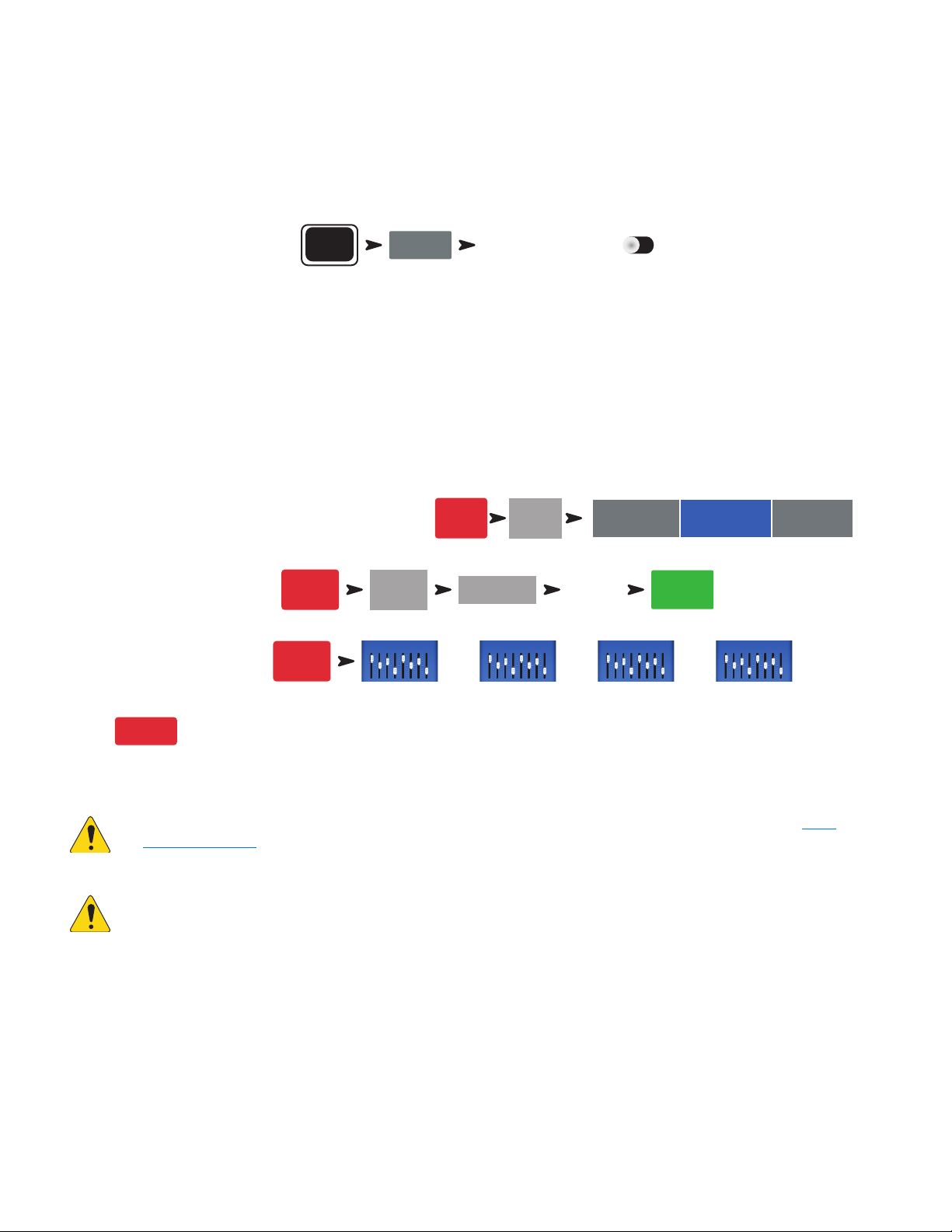
To Enable or Disable Phantom Power (+48V):
Mic
48V
Phantom power is also accessible from the channel Setup screens.
Work on Your Inputs
Ask the performers in turn to do what they do to make their audio contribution to the performance. Without
un-muting their channels, bring the channel’s input gain Trim up while watching the channel meter on the
Home screen. What you are looking for is a meter that is bouncing around the 0 mark when the performer is
producing a normal output level.
TIP:
During sound check performers will usually not play as loudly as they do in an actual
performance so keep this in mind and allow a little extra headroom.
Acceptable
0 00
0
With the performer performing, un-mute the channel and bring the fader up until the desired performance level
is reached.
If you are using one of the internal channel presets, this channel should already be sounding good. If it’s not
what you’re looking for, try some of the other preset choices. For most instruments and musical styles, there will
be a preset that works well. If not, you'll need to dive into the channel and dial it in manually.
To Adjust Channel Parameters:
At the top of the screen, select the tab for the channel processing element you want to work on.
10
Page 20
Simple and Advanced Mode
Inputs 1-8
In 1
Auxes
-40 -20 -10 U
10
Aux Masters
Aux Out 9-14
TouchMix mixers offer two modes of operation:
•
Simple Mode
values of any Advanced-mode controls.
•
Advanced Mode
You can select Simple and Advanced modes individually for an EQ, Gate, Compressor or Effect. Note that the Stereo and Mono Delays do not have a
Simple mode. Look for the Simple button on the screen. Or you can make the selection globally.
– Presents the user with a reduced set of controls. It’s important to know that switching into Simple mode does not alter the
– Presents all mixer controls to the user.
To Globally Select Simple / Advanced Mode:
Menu
Simple
OR
Advanced
Auxiliary (Stage Monitor) Mixes
There are two general approaches to setting up stage monitor mixes:
Input by Input
With all the performers on stage, ask each performer in turn to play or sing just one thing (Kick, Snare, Guitar, Sax, etc). Ask each performer how
much of that instrument they want in their monitor. Our guess is that they will all say “that’s plenty” during sound check and then ask for lots more
after the first song – just sayin’.
To Set Up Monitor Mixes One Input at a Time:
You will see sliders representing the send levels of the input to all the aux mixes. If any auxes are linked for stereo, the linked pair will have a Level
control and a Pan control.
Adjust
Mix On Faders
Sometimes it’s preferable to set up a complete mix for one auxiliary output at a time. On the left side of the mixer’s screen you will find buttons
that directly access the Auxiliary mixes. Touch one of the Auxiliary Select buttons to go to the mix you want to work on. Use the faders to adjust the
sends to the selected Aux Mix. Use the Nav Strip to move between fader banks.
Note that you can Mute an individual channel in an Auxiliary mix without muting it anywhere else.
for each performer in turn then use the
Prev
buttons to move through the channels.
Next
Output Processing
Like the input channels, the outputs (Main L/R and Aux Outputs) have their own processing.
To access Main Output Processing:
To access Auxiliary Output Processing:
Each output includes a full complement of processing and other functions including:
TIP:
There are times when several mixes will be similar to each other. To speed set-up, refer to "Copy & Paste" on page 20.
Main
Aux 1
11
Page 21

Overview Tab
Overview
Displays an overview of the output channel settings including Delay, DCA and Mute Group Assigns, Pre/Post pick-off points (auxiliaries only), Aux
Send Levels (see Matrix Mixing).
PEQ Tab
PEQ
Six-band parametric EQ with High / Low-Cut filters and a Real Time Analyzer (RTA)
This tab displays the six-band, parametric equalizer plus the Low and High-Cut Filters. The 6 bands of parametric EQ can be individually bypassed
using the numbered buttons. Bands 1 and 6 may be switched from parametric to shelving operation. You can use the two-finger pinch / zoom
gesture to adjust the Q for the selected Band.
Touch the
(RTA)" on page 102).
Low-Cut / High-Cut filters – These filters are used to roll off high or low frequency content. There are a number of possible applications.
• For stage monitors, it is common to roll off low frequencies at 80 – 100 Hz. There is usually ample low frequency energy on stage without any
help from the monitors. Keeping it out of the monitors can reduce “rumble” on stage and in the house.
• For speech only systems, rolling off low frequencies can reduce microphone handling noise or, if outdoors wind noise.
• Fill speakers may not need any additional low-frequency energy as there is ample bottom end coming from subwoofers.
• There is a technique known as “subs on auxes” in which the subwoofer is fed from one of the auxes while the main speakers are fed from the
mixer’s main outputs. Only those instruments that contain low-frequencies are sent to the subwoofer. This provides more control over the lows
and can help keep the bottom end tighter. If this is being done, the Low and High-Cut filters could be used to set the crossover point between
subs and main speakers.
RTA On
NOTE:
button to activate / deactivate a Real Time Analyzer display for the channel. ("Real-time Analyzer
When the RTA is not enabled, the Parametric EQ screen is enlarged to occupy both the RTA and PEQ screen area.
GEQ Tab
GEQ
One-third octave graphic equalizer with an RTA
In addition to the Real Time Analyzer (RTA), this tab displays two, overlaid 1/3 octave graphic equalizers.
• GEQ: The solid faders [Insert Image] control the user adjustable graphic equalizer. The “GEQ” switch may be used to bypass (Out) or activate
(In) this equalizer. The “Reset” button will return the GEQ sliders to 0.
• Tuning Wizard EQ: If the “Tuning” switch is set to “In” a set of ‘ghost’ faders
(1) is displayed to indicate the settings resulting from adjustment by the Room
Tuning Wizard (See "Room Tuning Wizard" on page 22). The ‘ghost’ faders are
indicators only and are not adjustable.
The GEQ and the Tuning Wizard EQ are additive. So 3 dB boost from the Tuning
Wizard and a 2 dB boost from the GEQ at the same frequency will result in a 5 dB
total boost.
Touch the
display for the channel. "Real Time Analyzer (RTA)" on page 18
RTA On
button to activate / deactivate a Real Time Analyzer
1
12
Page 22
Touch the
Anti-
Units
Tuning Wizard
button to go to the Room Tuning Wizard screen.
Anti-Feedback Tab
Feedback
Anti-Feedback Wizard and Manual operation
The Anti-Feedback system automatically identifies and displays suspected feedback frequencies. When a suspected feedback frequency is
identified, a single touch applies a filter at that frequency. In addition a Feedback Wizard can assist in finding and cutting feedback-prone
frequencies.
Limiter Tab
Limiter
Displays the limiter and its controls. We strongly encourage the use of the limiter for In Ear Monitors.
Auxes Tab (TouchMix-30 Pro only)
Auxes
The Main L/R outputs may be returned to Auxiliary mixes 1 – 14. Auxiliary mixes 9 -14 may be returned to Auxiliary mixes 1 – 8. Refer to "Patch
Matrix (TouchMix-30 Pro only)" on page 21 for more information.
Presets Tab
Presets
Preset save/recall
This tab offers a Factory Preset named Reset that returns all output control parameters to their factory values. In addition, any settings you make
can be stored to and recalled from either internal or external (USB) memory.
The Preset Tab also includes factory voicings for QSC E-Series and K.2 Series loudspeakers. These settings are also available for QSC PLD and GXD
amplifiers. The E-Series voicings are intended for use with other amplifiers that lack DSP. An “X” suffix after the preset name indicates the preset
is intended for use with a sub-woofer. Do not use the mixer presets and the PLD or GXD voicings together – your E-Series speakers will not sound
twice as good.
Setup Tab
Setup
The Setup Tab includes the following utility functions for the output.
Rename
Linking
Delay
Delay is most commonly used for remote fill speakers. The objective is to set the delay so that
the sound from the primary system arrives at the listeners ears just slightly (20 – 30 msec)
ahead of the sound from the fill system. When done correctly, the listeners perceive the sound
as coming from the primary system even though most of what they hear is from the fill speakers.
In venues with very deep stages, the engineer will sometimes delay the house system so that
it time aligns with the back-line. In other words, set up the system so that the sound from the
Aux
Link
Joe’s Monitor
This Links odd-to-even pairs of auxiliary mixes to create a stereo mix.
Touch the field to enter a name for the output (not available on Main output).
Delay
In
55.0
48.9
16.8
feet
ms
meters
13
Page 23
actual kick drum and the reinforced kick drum arrive at the listeners’ ears at the same time. The delay provides a read out in msecs. (up to 100),
Channel Safe
Channel Safe
meters (up to 34.3) and feet (up to 113).
Channel Safe During Scene Recall
When a Scene is recalled, it sets all the controls to the settings saved with the Scene. There
may be times you do not want to change a specific output channel, or channels. The default
position, Recallable, allows the scene to recall the saved settings. The Safe position does not
allow the scene to change any settings of thischannel.
During Scene Recall
During Scene Recall
Recallable Safe
QSC Amplifier and Speaker Settings:
Refer to "Using TouchMix with QSC Amplifiers and Loudspeakers" on page 9 and "QSC GXD Amplifier Settings" on page 10. Also see "What
is a Channel Preset?" on page 2 for information on preset voices for QSC E-Series loudspeakers.
Aux Pick-off
Available for the Aux mixes only, these buttons determine whether the point from which the signal is taken is before or after the channel fader. For
most monitor mixing applications, this should be set to Pre Fader.
Assignments
These buttons assign the output to a Mute Group or a DCA Group. Refer to "Mute Groups" on page 6 and "DCA Groups" on page 6 fordetails.
Pre Fader Post Fader Pre All
DCA 1 Mute 1
Pre Dynamics
E Series K SeriesAmpliers K.2 Series KLA Series KW Series
Recording
TouchMix mixers make it easier than ever to capture a live performance in a stereo or a multi-track recording. All you need is a USB hard-drive.
NOTE:
hard-drives available for us to test them all so there are certainly many unlisted drives that will work well with TouchMix. Higher speed
drives (>7200 RPM) tend to work best. Some higher speed drives don’t do their best when powered from the USB port but will work
when used with an external power supply. We have also had very good luck with solid state drives. USB thumb-drives may work for
recording a small number of channels but are not recommended although users report good results with better quality, USB 3.0
thumb drives.
Hard-drive requirements – A list of hard-drives that QSC has qualified may be found at qsc.com. There are far too many
Formatting the drive
The drive must be formatted as FAT 32 and de-fragmentation improves seek time.
If formatting the drive from an Apple Mac computer select MS-DOS (FAT) as the Format and MBR (Master Boot Record) as the scheme.
The TouchMix mixer can also format a drive. The format function is available from the Recording Setup screen.
Drive space for recording
Be sure that there is sufficient space on the drive for your recording. To calculate the space required for your recording…
• For 48 kHz – Space required (in MB) = 11.5 x minutes x tracks
• For 44.1 kHz – Space required (in MB) = 10.6 x minutes x tracks
It is good practice to have more disk space available than you need. If the drive is nearly full, TouchMix has to look for nooks and crannies of
available space. This will result in fragmented wave files and potential loss of audio data and synchronization across tracks. At approximately 3
hours of non-stop recording, the maximum file size supported by FAT32 is exceeded. To avoid problems, stop and then resume recording. It is not
necessary to create a new session. The TouchMix displays a pop-up that warns you when this limit is approaching. If you do exceed the FAT32 limit,
track synchronization may be lost.
NOTE:
rendering of objects on the mixer screen resulting in lagging display of control movement.
Depending on the number of tracks recorded and the performance of the hard drive, multi-track playback may slow down the
14
Page 24
Transferring tracks between TouchMix and DAW
Mixer Setup
Rec/
Play
Recording
Mode
Inputs 1-8
Inputs 9-16
Inputs 17-24
Stereo In/2-Trk
A utility application – TouchMix DAW Utility - that facilitates transferring tracks between TouchMix mixers and Digital Audio Workstations is available
for download at www.qsc.com. The application runs on Mac or Windows computers.
Sample Rate
In general, use 44.1 kHz for CD projects, and 48 kHz for video projects. Do not change sample rate while recording.
To View or Change Sample Rate:
Menu
Sample Rate 44.1 kHz 48 kHz
Multi-Track Recording
All TouchMix models are capable of recording all audio inputs plus a stereo mix directly to a USB hard-drive (see above). The audio is captures as a
32-bit, floating point wave file.
Recording and Playback Capacity
• TouchMix-30 Pro: 32 tracks (30 inputs + stereo mix)
• TouchMix-16: 22 tracks (20 inputs + stereo mix)
• TouchMix-8: 14 tracks (12 inputs + stereo mix)
Connect a hard-drive (see above) to one of the USB inputs of the mixer.
Set the External Recording & Playback Mode to Multitrack:
To create a recording session:
To select channels to record:
Rec/
Play
Rec/
Play
Recording
Setup
And/Or
New Session
Enter a
name
And/Or
Stereo MP3
USB Drive Playback
Create
And/Or
Multitrack
USB Drive
Multitrack
DAW
Touch
Arm
for each channel you want to record.
Once all the channels you wish to record have been armed, touch (Record Button) to begin recording. Touch the (Stop) button to end recording.
NOTE:
User buttons may be assigned to Arm / Disarm and select Track or Input as the source for all channels at once. "User
Buttons" on page 24
IMPORTANT:
Do not unplug your TouchMix until you have stopped recording! If you do, your recorded tracks will not be usable. You
must end the Session by touching the STOP button on the transport control. Doing so writes a header file that is needed in order to
play back the recording or import it into a DAW.
The TouchMix mixers permit over-dubs, however only the last recorded track will play back on the mixer. Earlier passes are left on the drive and
may be imported into a DAW.
15
Page 25

Multi-Track Playback & Mix Down
Inputs 1-8
Inputs 9-16
Inputs 17-24
Stereo In/2-Trk
Stereo In/2-Trk
Stereo In/2-Trk
Mixer Setup
Tracks recorded on the TouchMix mixers may be played back and mixed down on the mixer.
USB Session
Vocal 1 - Joe
Backup Voc 1
Recall
To load a recorded Session:
Rec/
Play
Recording
Setup
A list of available recordings is displayed. Select the recording you want to play and touch Recall. Now that the session is loaded, the next step is to
switch the input channel source to “Track”.
To select Track as the input source:
Touch
Track
for each channel you want to play back.
Rec/
Play
And/Or
And/Or
And/Or
Use the Locator bar at the bottom of the Rec / Play screen to set the starting point for recording.
Mix Down
There are three ways to mix down your multi-track recording.
• Import the multi-track waves into a DAW (digital audio workstation). See “Transferring Tracks between TouchMix and DAW” above.
• Record the mixer’s analog output to an external 2-track recorder. Simply connect the TouchMix Main L/R outputs to the inputs of your 2-track
device.
• Record a stereo mix to DAW via the USB DAW connection (TouchMix-30 Pro only).
• Internal mix down to 2-track.
To mix down to 2-track:
1. Recall the session and set up the mixer for Playback as described above.
2. From the Record/Play Screen:
2-Trk Rec
If you would like to use the Main L/R channel processing on the stereo mix, select
Return to the Rec / Play screen and touch
to begin mix down. When you are finished, touch on the transport controls.
Post
Main L/R
, if not, select
Pre
. Touch
Arm
.
What to do with the 2-track mix down?
• Export to a DAW for further processing and to be edited into individual songs. The wave files may be found in the last two folders of the directory
containing the session.
• TouchMix-30 Pro only – Create an MP3 version from the mixer. The TouchMix-30 Pro has the capability of rendering the 2-track mix as an MP3 file.
To make an MP3 version of Tracks 31/32:
2-Trk Rec
Export 2-track
The MP3 audio file will be saved to the "\<session name>.tmRecord\exports" directory.
DAW Interface
The TouchMix-30 Pro is capable of interfacing to Mac OSX computers with Core Audio. Core Audio was introduced with OSX version 10.3. The
mixer must be connected to the computer using a USB type-B connector attached to the “USB DAW” port of the mixer. To verify that your Mac is
connected, open the Audio MIDI Setup utility on the computer (Finder > Applications > Utilities > Audio MIDI Setup). “QSC TM30 Pro” will appear in
the Audio Devices window. Select the mixer and make sure that the sample rate on the Mac matches that of the Mixer.
To View or Change Sample Rate:
Menu
Sample Rate 44.1 kHz 48 kHz
16
Page 26
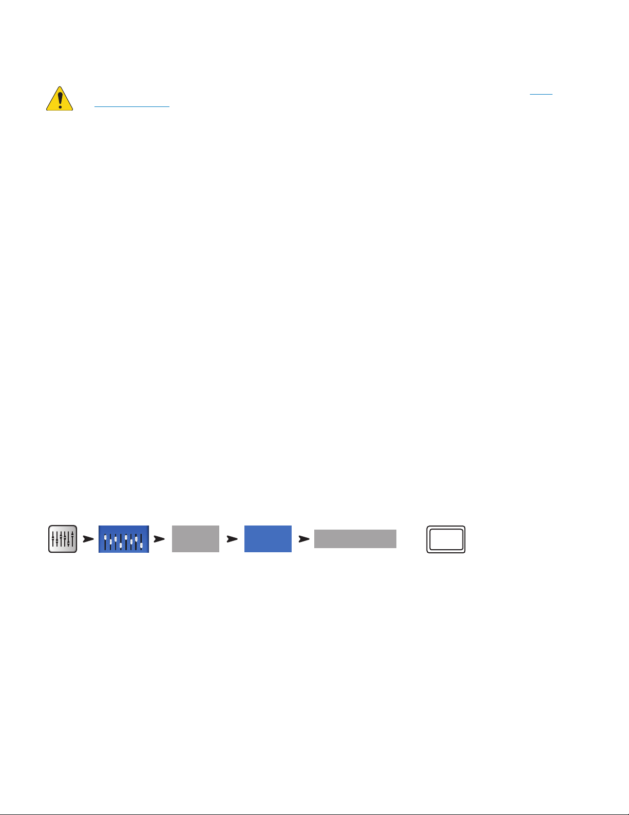
Your DAW software will also likely require some configuration to connect with the TouchMix-30 Pro. See your DAW software documentation for
Aux Masters
Anti-
information on this topic. There is also a guide to configuration of some common DAW software at www.qsc.com.
NOTE:
Buttons" on page 24
User buttons may be assigned to Arm / Disarm and select Track or Input as the source for all channels at once. "User
Anti-Feedback System
The TouchMix-30 Pro includes twelve narrow-band, anti-feedback filters on each output (eight filters for TouchMix-8 and TouchMix-16). These
filters are extremely useful for eliminating feedback frequencies while having very little effect on overall tonal balance. The filters may be adjusted
manually or automatically using the “Feedback Wizard” (see below).
Manually Ringing Out a System
In order to identify feedback frequencies, it’s necessary to deliberately make the system feedback. This process is known is “ringing out” or
“squeaking” the system. Here’s how an experienced sound system operator would go about it.
• Bring all mixer output faders to minimum
• Place all microphones and speakers in position
• Bring the input level of power amplifiers or powered speakers to the level that will be used in performance.
• Bring the input gain and channel faders for the mix you’re working on to the approximate level they will be at during the performance.
• Warn anybody who is around that you are going to make some unpleasant noises.
• Slowly and carefully bring up the fader for the output you are working on until the system begins to feedback.
• Be prepared to quickly back down the fader if the feedback really starts “taking off”.
• It may be necessary to have someone talk or shout into a microphone to “excite” the system into feedback.
• Adjust the frequency of a filter to match the feedback frequency and reduce the gain until the feedback goes away.
• Repeat until you have achieved sufficient system gain without feedback.
Using the Feedback Wizard
The tricky part is to identify the feedback frequencies. Fortunately, you don’t need to identify them because your TouchMix has built-in tools to do
that for you. Here’s how to use those tools.
To access the Anti-Feedback System:
Aux 1
Feedback
Feedback Wizard
OR
Pre-Feedback Wizard Checklist:
• Microphones and loudspeakers in their performance positions.
• Input channel gain and level settings approximately at performance levels.
• Zero the filter bands or touch Reset. The Wizard won't use a filter unless its gain is set to 0.0 dB Cut.
• Output you're working with set at a level that's slightly below its threshold of feedback.
• If the space is very quiet, turn on some noise using the control in the Feedback Wizard.
• The Wizard will cause feedback to occur briefly at levels that may be uncomfortable to those who are sensitive to such things. Let them
knowit'scoming.
Anit-
Feedback
Follow the step-by-step instructions on the screen. The Feedback Wizard gradually brings up the Master Fader. As it does, feedback ring
frequencies will emerge. The Feedback Wizard will identify the frequency and automatically apply a notch filter. You may continue the process until
the Feedback Wizard has used up all Anti-Feedback Filters or you may touch “Done” or “Anti-Feedback Wizard” at any point. Typically, eliminating
five or six feedback frequencies should be sufficient.
17
Page 27

Licensed to Kill Feedback
The Feedback Wizard algorithm is looking for suspected feedback frequencies even when the Wizard isn’t active. The most recently identified
suspect frequency is displayed in the “Feedback Frequency” window. Simply touch the
applied to the frequency.
Lingering Feedback Problems
If you have used the Wizard or Manual Kill function to apply all anti-feedback filters and your system is still unstable (prone to feedback) there are
several other possibilities…
• Improper microphone selection or placement.
• Improper microphone technique.
• The performer is cupping the head of the microphone because he’s seen the cool guys on videos do it. This actually turns a directional
microphone into an omni-directional microphone and destroys any off-axis feedback rejection the microphone has.
• Or an inexperienced talker is holding a hand-held microphone at chest level while pacing in front of the speakers.
• Improper loudspeaker selection or placement.
• Unrealistic expectations. If you point a microphone at a loudspeaker and increase the gain enough, it will eventually feed back.
• Excessive EQ boost elsewhere in the signal chain.
• Compressor latch
Manual
button and an Anti-Feedback Filter will be
Kill
More about the Anti-Feedback System
At the bottom of the Anti-Feedback screen is a “Filter Depth” control. This can be used to vary the depth of all the Anti-Feedback Filters.
The Feedback Wizard and Manual Kill function will not readjust a filter that has already been set. They will only use an Anti-Feedback Filter that is
set to 0.0 dB Cut. If all twelve filters are already in use neither function will have any effect. To make an Anti-Feedback Filter available for the Wizard
or Manual Kill function, simply rotate the gain of a filter to 0.0 dB or touch the “Reset” button to zero all filters (be careful when you do this because
you may be removing the filters that have been preventing feedback).
Filters are applied in the order that feedback frequencies are identified and do not correlate to the left to right arrangement of the controls. This
means that Filter 1 could be applied to a high-frequency while Filter 12 is applied to a very low frequency. The filter controls and on-screen
indicators are numbered and color-coded for easy identification.
There are anti-feedback systems that actively search for and filter feedback in real-time during performance and they can be quite effective for
speech applications. These systems can struggle with music because it’s difficult to tell the difference between unwanted sound system feedback
and desired electric guitar feedback or a sustained note on an organ or synthesizer.
Real Time Analyzer (RTA)
An audio Real Time Analyzer breaks the spectrum into frequency bands – 1/3 octave bands for the TouchMix RTA – and displays the amplitude of
the signal in each band. It is useful for visualizing the frequency balance of a signal and for identifying feedback frequencies.
TIP:
The TouchMix mixers also include a noise generator. Some may attempt to use the noise generator, output EQ and RTA to “tune”
the system for “flat” response. This is an overly simplistic approach to system tuning and will rarely if ever deliver the desired results.
In addition, the prolonged output of noise can stress loudspeakers and annoy others. Please see “Tuning Wizard” for a more useful
approach to dialing in your rig.
The TouchMix contains two 31-band, Real Time Analyzers. These may be displayed on any combination of the mixer and tablet devices but only two
RTA are available at one time. If an operator attempts to open a 3rd instance of the RTA, a confirmation prompt will appear.
One RTA (the Channel RTA) is available on all input and output EQ screens and may be displayed by touching the “RTA On” button located above the
EQ / RTA window.
NOTE:
The second RTA (the Independent RTA) can be displayed by pushing the RTA button on the mixer or touching the RTA button on the remote control
app. This RTA offers options for source selection. The user may select…
• The Main L/R signal
• The signal from any Auxiliary mix
• The Talkback microphone input
• Follow Cue (whatever is heard in the Cue bus is displayed on the RTA)
NOTE:
When the RTA is not enabled, the Parametric EQ screen is enlarged to occupy both the RTA and PEQ screen area.
The TouchMix-8 and TouchMix-16 RTA is similar in operation but only a single RTA is available.
18
Page 28

Mutes
The TouchMix has a sophisticated and powerful Mute system. In addition to the Mute Groups (See "Mute Groups" on page 6) inputs and
individual channel sends to individual aux mixes may be muted independently.
Main Mutes: When a channel is muted while the Main L/R is selected, the channel is also muted to all Auxiliary and FX mixes. This is true whether
the channel was muted using the channel Mute button or a Mute Group.
Auxiliary Mutes: It is sometimes useful to mute an individual input to only one auxiliary mix. When an Auxiliary is selected by touching one of the
buttons on the left of the screen, the Mute button that is displayed with the channel faders will effect only the selected auxiliary mix.
The Mute buttons have three states…
Mute
•
Mute
•
» With Main L/R mix selected, indicates that the channel has been muted by pressing the channel Mute button. The
channel’s signal is also muted for all auxiliary sends.
» With Auxiliary mix selected, indicates that the channel is muted for the currently selected Auxiliary mix. This affects
only the muted channel and only for the selected Aux mix.
Mute
•
» With Main L/R mix selected, indicates that the channel is muted from a Mute Group, or DCA Group*.
: Indicates the channel is not muted.
:
:
This is an indication that the channel is muted by something other than the Mute button you’re seeing.
» With Auxiliary mix selected, indicates that the channel is muted from a Mute Group, DCA Group or at the Main L/R
mix.
» For FX Returns, indicates that the channel is muted from a Mute Group, DCA Group or FX Mute button
NOTE:
*A DCA mute will not mute an auxiliary send that is set to a pre-fader pick-off point.
19
Page 29
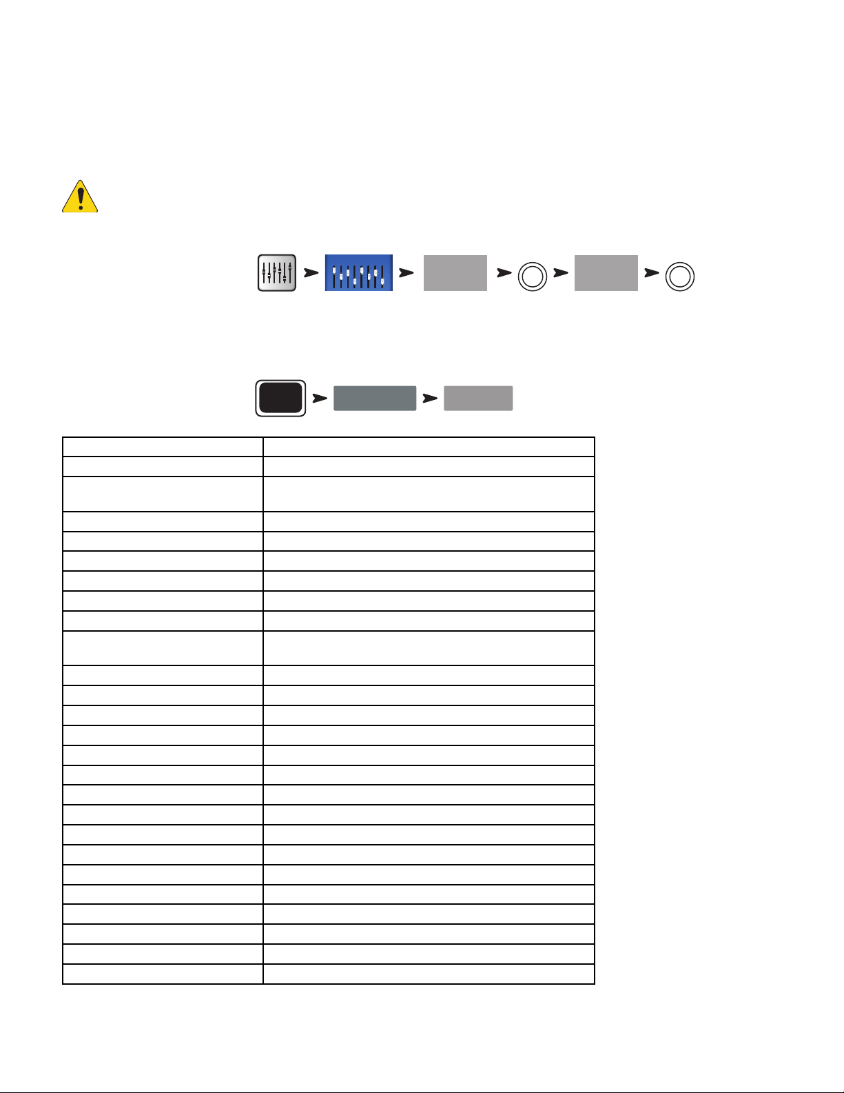
Copy & Paste
Aux Masters
Copy
Paste
The TouchMix-30 Pro has a powerful but simple copy and paste function that is operated by the U7 (copy) and U8 (paste) buttons (U2 and U3 on
the TouchMix-8 and TouchMix-16). Copy and Paste is context sensitive so that what you are looking at is what will be copied. Only like things may
be copied and pasted from and to each other. For example, a PEQ cannot be pasted to a GEQ. The table below explains what parameters will be
copied and pasted.
NOTE:
The copy buffer retains the last item of each type that has been copied. If, for example a GEQ setting is copied and then a
Gate is copied, both will reside in memory. If a GEQ is displayed, Paste will recall the copied GEQ parameters. If a Gate is displayed,
Gate parameters will be pasted.
To copy and paste parameters:
Aux 1
U7
Aux 5
U8
The example above shows the mix that’s on Auxiliary 1 copied to Auxiliary 5.
After set-up is complete, it may be useful to clear the Copy/Paste buffer. This will prevent accidentally pasting parameters during the show. To clear
the Copy/Paste memory:
To clear the Copy/Paste buffer:
What’s Displayed What will be copied & pasted
Main or Auxiliary Faders View Fader and Pan
Input Channel Overview Tab EQ, Compressor, Gate, FX sends, Aux Sends, Digital Gain, Delay, Group
Input Channel EQ Tab All channel EQ parameters
Input Channel Comp Tab All channel Compressor parameters
Input Channel Gate Tab All channel Gate parameters
Input Channel FX Tab All channel FX send levels
Input Channel Aux Tab All channel Auxiliary Send levels and Pan positions
Input Channel Setup Tab Recording Arm, Polarity, Delay, Digital Gain, Group assignments
Output Channel Overview Tab PEQ, Limiter, FX sends, Aux Sends, Delay, Group Assigns, Polarity, Pick-
Output Channel PEQ Tab All channel PEQ parameters
Output Channel GEQ Tab All channel GEQ parameters
Output Channel Anti-Feedback Tab All channel Anti-feedback parameters
Output Channel Limiter Tab All channel Limiter parameters
Output Channel FX Tab All channel FX send levels
Output Channel Aux Tab All channel Auxiliary Send levels and Pan positions
Output Channel Setup Tab Recording Arm, Polarity, Delay, Digital Gain, Group assignments
FX Channel Overview Tab Current Preset, EQ, Pick-Off Point, Group Assigns, Polarity
FX Channel EQ Tab All FX channel EQ parameters
FX Channel Preset Tab Processor and Preset selection, FX Returns and Pans to Aux
FX Channel Aux Tab All FX Channel Auxiliary Send levels and Pan positions
Sub Group Overview Tab PEQ, Limiter, FX sends, Aux Sends, Group Assigns
Sub Group EQ Tab All Sub Group PEQ parameters
Sub Group Limiter Tab All Sub Group Limiter parameters
Sub Group FX Tab All Sub Group FX send levels
Sub Group Aux Tab All Sub Group Auxiliary Send levels and Pan positions
Menu
Assigns, Polarity
Off Point (Auxes only)
Clear Copy/Paste
Yes
20
Page 30
Patch Matrix (TouchMix-30 Pro only)
The Patch Matrix is a powerful tool but it is also one that can create problems. Make sure you clearly understand this function before attempting to
useit.
The TouchMix-30 Pro has audio inputs plus a set of graphical controls and processing for each audio channel. Let’s call these “Inputs” and
“Channels”. By default, the audio for Input 1 is controlled and processed by Channel 1, Input 2 is controlled and processed by Channel 2 and…,
well you get theidea.
There are occasions when it is useful to route an Input to an alternate Channel. Before you do, there are a few things to understand.
• The Patch Matrix only effects the digital audio signal. So rerouting Input 1 to Channel 6 does not change the fact that input gain trim still has to
be set using the Trim 1 control.
• Unless you keep track of the changes you’ve made, altering the default patching can make signal tracing confusing. You know the microphone is
connected to Input 1 but why isn’t there any signal showing up on Channel 1?
That said, there are some reasons to use the Patch Matrix. The first is simply to rearrange the order in which inputs appear on the controls. Before
making a change on the Patch Matrix, ask yourself if it wouldn’t be easier and potentially less confusing to physically re-patch the input. If the
answer is no, here’s how to proceed.
To access the Patch Matrix:
NOTE:
When the Patch Matrix is loaded for the first time after the mixer was powered on, it may take a few moments to display. The
Menu
Patch Matrix
Patch Matrix displays the Analog Inputs across the top of the screen and the Destination Channels down the right side. Connection is
indicated with lines and a blue circle.
To change a connection:
Input
.
5
8 In 8
Input
you want to re-patch. The button changes
5
where you want to route the input.
8 In 5
, the lines and blue circle move to indicate the new routing.
•
Touch the button of the
•
Touch the Channel
» The Channel changes to
•
To route the input to a second Channel, touch
11 In 5
of the second Channel to which you want to route the
input.
•
If you make a mistake in selecting a Channel, simply touch it again to restore the previous routing.
•
Touch the input button to complete the re-patch.
TIP:
Why would one want to route the same input to two Channels? This is known as “Multing”. The term comes from old-school
analog patch bays that had some jacks wired so that a single signal could be patched to multiple destinations. Here’s an example
of how it’s used. Let’s say you’ve got an acoustic guitar on stage and you’ve dialed it in for the main speaker system. But no matter
what you do, you can’t get it to sound right in the monitors without compromising the sound the audience hears. You could use an XLR
Y-Cable to patch the guitar into two mixer channels, or you could use the Patch Matrix to mult the guitar to a second Channel. Send
that channel only to the performer’s stage monitor and adjust as needed to make our demanding guitarist happy.
To reset the Patch Matrix to default routing:
Menu
Patch Matrix Reset Reset
Patch Matrix settings may also be saved and recalled using the
21
Save / Recall
button.
Page 31

Room Tuning Wizard
Aux Masters
The Tuning Wizard assists the operator in adjusting an output equalizer to compensate for variations in room acoustics and loudspeaker response.
The three TouchMix models handle measurement microphone connection in slightly differing ways.
TouchMix-30 Pro
The measurement microphone is connected to the Talkback input and is controlled entirely from within the Room Tuning Wizard.
TouchMix-8 or TouchMix-16
For these mixers the microphone is connected to input 8 (TouchMix-8) or input 16 (TouchMix-16). When the Room Tuning Wizard is opened,
channel 8 (or 16) is automatically muted and its input signal is routed to the Room Tuning Wizard. The measurement microphone may then be
connected to input 8 (or 16) and the Room Tuning process may be run. Upon completion, the input channel is muted to allow disconnection of the
measurement microphone and re-connection of the instrument previously connected. The input 8 (or 16) channel mute can then be lifted by the
operator. The Room Tuning Wizard has no effect on the input channel settings.
Before proceeding with the Tuning Wizard, listen to your system in the room using material with which you are familiar. Many contemporary
loudspeaker systems – especially powered loudspeakers such as the QSC K.2, K, KW and KLA series – have been carefully tuned by design and
will sound very good with little or no additional equalization.
That said, here’s how to use the Room Tuning Wizard. Before you begin, you will need a measurement microphone with flat response, a microphone
stand and a microphone cable that’s long enough to reach from the mixer to the coverage area of the speakers being measured.
When using the Room Tuning Wizard, it’s best to do so before applying any of the output channel’s parametric EQ or Anti-Feedback filters.
To access the Room Tuning Wizard:
OR
Aux 1
3. Select an output to tune
Aux 2
4. Select a measurement method.
NOTE:
The Low Precision method uses just a single measurement while the Medium and High Precision methods require
multiple measurements and repositioning of the microphone. The Skip Measurement method will retain the results of the last
measurement but allow selection of one of the other target tuning curves that we’ll discuss in a moment.
5. Touch
Next
. The wizard displays instructions and a guide to microphone placement.
Wizard
Low Precision
(Fast)
Tuning Wizard
GEQ
Medium Precision
OR
Tuning Wizard
OR
High Precision
OR
Skip Measurement
(Use Previous)
6. Enable
7. Touch
NOTE:
Most measurement microphones are condenser microphones and require phantom power which may be switched on from
the Room Tuning Wizard screen.
Talkback Mic Phantom On
Begin
.
O
if needed.
22
Page 32

8. Follow the directions and adjust the
Noise
Level
-13.5 dB
so that the RTA displays a moderate level of activity.
9. Touch
Measure
NOTE:
. The mixer produces the test signal and captures the measurement data.
Each output of a TouchMix mixer actually has two graphic equalizers. One is used by the Tuning Wizard to apply corrections
based on the measurement data. Settings for this equalizer are indicated by the outlined or “ghost” fader caps on the GEQ screen. The
other equalizer may be adjusted by the user.
10. Select a target tuning.
» Select
Flat
– The wizard flattens the system response using the Tuning EQ and sets the user EQ to flat. You
can adjust to taste from there.
» Select
Live
– The wizard flattens the system response and applies a User EQ setting that works well for live
sound reinforcementsystems.
» Select
Keep Existing
– The wizard flattens the system response using the Tuning EQ but leaves the user EQ settings
untouched.
11. Touch
measurement again.
12. Touch
13. Touch
Navigate To GEQ
Restart
Finish
if the measurement is interrupted by, for example, unexpected, loud ambient noise. Perform the
to continue.
to view the GEQ settings.
23
Page 33

User Buttons
The TouchMix-30 Pro has eight user-assignable buttons (U1 – U8) while the TouchMix-8 and TouchMix-16 have four (U1 – U4). The remote control
apps for all models provide 8 user buttons. The following are assigned by default:
TouchMix-30 Pro TouchMix-8 / TouchMix-16
U1
•
•
•
•
•
•
•
•
– Navigate Left (moves the selection left)
U2
– Clear Clip (clears clipping indication from the Navigation Strip)
U3
– Clear Cue (clears all cue selections)
U4
– Navigate Right (moves the selection right)
U5
– Play/Stop (starts or stops playback)
U6
– Rec/Stop (starts or stops recording)
U7
– Copy (see Copy & Paste)
U8
– Paste (see Copy & Paste)
The User Buttons may be reprogrammed to suit your preferences.
To program a User Button:
Menu
To complete the programming:
User Buttons
Assign Assign
User 1
Nav Left
U1
•
•
•
•
•
•
•
•
– Navigate Left (moves the selection left)
U2
– Copy (see Copy & Paste)
U3
– Paste (see Copy & Paste)
U4
– Navigate Right (moves the selection right)
U5
– Play/Stop (Tablet app only)
U6
– Rec/Stop (Tablet app only)
U7
– Clear Clip (Tablet app only)
U8
– Clear Cue (Tablet app only)
Action Selection Detail
Name
Type Name
NOTE:
Touch the
TIP:
The Name displays on the tablet app User Buttons.
Reset
button to restore the default assignments.
For instant navigation to a particular screen, there’s a simple shortcut method to program a User Button. Let’s say that you
want to be able to get to the input channel overview of the lead singer’s channel (channel 12) quickly. Simply navigate to the Channel
12 Overview tab and hold a User Button for two seconds. Touch “Yes” and the User Button will now take you to the Channel 12
Overview screen no matter where you are.
MIDI Control
A USB-over-MIDI device such as a foot switch may be used to control some TouchMix-30 Pro functions. MIDI Control is similar in function to User
Buttons.
1. To program MIDI Control:
Menu
MIDI Setup
2. With a compatible MIDI device connected to the mixer, touch
3. Send a MIDI command to the mixer and that command will now be associated with the selected MIDI button.
4. To assign a function to the "learned" button:
Action Selection Detail
MIDI 1
Not in use
Learn MIDI
.
24
Page 34

Security
The TouchMix mixers have multi-level security that allows you to assign passwords to various levels of functionality. You can give users access to
only the functions they are authorized to use.
To set up Security:
IMPORTANT:
Menu
Security
Leaving a password field empty allows anyone to access the associated functions without any log-in. The Security
Security Settings
Setup menu offers four levels of access:
• Administrator:
Logging in as Administrator gives access to all mixer functions including Security Settings. If the mixer is accessible to others, it may be a good
idea to enter an administrator password to prevent mischievous or inadvertent password creation that would lock you out of your own mixer. Be
certain you can remember this password!
• All Access:
• No password: Anyone can access all functions other than Security Setup.
• Password protected: Access to Advanced functions requires password log-in.
• Simple Mode Only:
• No password: Anyone can access all functions (other than Security Setup) in Simple Mode only.
• Password protected: Access to all Simple Mode functions requires log-in.
• Levels Only:
In order to password protect the mixer from any unauthorized adjustment, create a password for this level.
• No password: Anyone can adjust level controls only.
• Password protected: Access to level controls requires log-in.
Further restriction can be placed on each access level.
• Overwrite Scenes & Presets: Allows or denies the ability to change a Scene or Preset in user memory.
• Recall Scenes: Allows or denies the ability to recall a scene from memory.
• Recall Presets: Allows or denies the ability to recall a preset from memory.
• Auto-lock: Sets a timer that automatically logs out after a preset period (up to 25 hours) with no activity at the mixer controls.
To manually log-out of the mixer.
Menu
Security
Lock/Logout
25
Page 35

Monitor (TouchMix-30 Pro only)
Mixer Setup
The monitor output is most commonly used to feed a pair of monitor loudspeakers.
Monitor
To adjust Monitor level:
Monitor
Use the Master Rotary Encoder.
The monitor pop-up includes the following controls:
•
Source Selector – Selects a signal for the Monitor output.
» Aux 1 through 14 – The monitor output signal is derived form the
selected Aux mix.
» Main LR – The monitor output signal is derived from the Main L/R output.
» Cue – The monitor output follows the Cue selection.
•
In – Engages / bypasses the delay.
•
Delay – The delay is used to align the audio coming from a distant stage
with the near-field monitor signal heard at the mixer position. Digital
readouts are in feet, milliseconds, and meters.
Touch
Close
or push
Monitor
to close the pop-up.
Monitor (TouchMix-16 only)
Controls the output level for the Monitor Cue
To adjust Monitor level:
Monitor
Use the Master Rotary Encoder.
Aux 1
Aux 5
Aux 9
Aux 13
Source
Aux 2
Aux 3
Aux 4
Aux 6
Aux 7
Aux 8
Aux 10
Aux 11
Aux 12
Aux 14
Main LR
Delay
In
Cue
0.00 ms
0.00 feet
0.00 m
Close
10
5
U
-5
-10
-20
-40
Monitor / Cue Level
NOTE:
– Controls the level of the Cue signal on the Monitor outputs.
By default, no audio signal is sent to the Monitor Outputs. To send
audiochannel signals (including Main LR) to the Monitor Outputs, enable the Cue
button for the channels you want to listen to.
Touch
Close
or push
Monitor
to close the pop-up.
Solo In Place (SIP) (TouchMix-30 Pro only)
When setting up a sound system, it can be very useful to mute all the inputs except for the one being worked on. This could be accomplished by
manually muting all the other channels but there’s a more convenient way.
To set up Solo In Place:
Menu
When Solo In Place is engaged, the input channels’ Cue buttons change color to light red and are labelled SIP. Touching a channel’s SIP button will
mute all the other input channels and the SIP button turns solid green. Multiple inputs may be soloed. The Cue system functions normally for the
mixer’s outputs.
The Solo In Place function does not affect FX returns. This means that when an input channel is soloed, any effect routed to that channel will still be
heard in the mix. If it is desirable to hear a channel soloed without effects, the FX Mute button may be used to mute all effects independently.
Solo in Place
IMPORTANT:
Solo In Place (SIP) is an extremely useful function for setup and troubleshooting but can be hazardous during a show.
Be certain to disengage Solo In Place when setup is complete.
26
Page 36

TouchMix Reference
Cue
Stereo Input
29/30
Trim Trim Trim Trim Trim Trim Trim Trim Trim Trim Trim Trim
13 2423222120191817161514
Trim Trim Trim Trim Trim Trim Trim Trim Trim Trim Trim Trim
1 2 3 4 5 6 7 8 9 10 11 12
Talkback
U3U2
U1 U4
0
U7
U8
Copy
U6U5
Talk
Wizard Info
Mic
48V
Aux
Mute
Groups
FX
Mute
Phones Monitor
Paste
TouchMix - 30 Pro
Home
Rec/
Play
Menu
RTA
Anti-
Feedback
13 1412
5
7 86
10 119
18
15
16
17
19
20
5
4
3
2
1
21
The information provided in this section gives you a detailed description of the screens and controls for the TouchMix-30 Pro and the
TouchMix-30 Pro remote apps. The screen shots provided are taken from the TouchMix-30 Pro iPad App, and because of a different screen size,
may appear slightly different than the TouchMix-30 Proscreens. The topics are in the order of the Info menu buttons on the mixer.
Getting Started
Top Panel and Remote-Device
Controls (T ouchMix -30 Pro)
1.
Trim knobs – Channels 1 – 24 adjusts analog input
signal level prior to A/D conversion.
2.
Color LCD touchscreen
3.
Cue headphone jack – 1/4” stereo headphone
jack. The output is controlled by clicking the Cue button on
a channel. Volume is controlled by pressing the Phones
button on the front panel.
4.
Stereo Input 29/30 jack− Channels 29 and
30 are permanently linked. The input is a 3.5 mm stereo phone
jack.
5.
User buttons – By default, these eight buttons are
assigned the following functions:
a.
U1 – Navigate left from the currently selected item
b.
U2 – Clear clip indicators
c.
U3 – Clear Cue indicators
d.
U4 – Navigate right from the currently selected item
e.
U5 – Play button for the currently selected Play-back file.
f.
U6 – Record button starts recording audio on the selected recording setup
g.
U7 – Copy the selected item
h.
U8 – Paste the copied item to another item of the same type
6.
Wizard button – Starts the TouchMix wizard. Choices are: FX Wizard, Tuning Wizard, Gain Wizard.
7.
Mic 48V button – Opens the Phantom Power screen. Turn Phantom Power on/off and view status for all channels.
8.
Info button – Opens the Info System but you already knew that or you wouldn’t be reading this.
9.
Aux button – Opens the Aux overview screen.
10.
FX Mute – Mutes or unmutes all FX channels.
11.
Mute Groups – Opens a screen where Mute groups may be controlled and edit
12.
Phones button – Push to display and select the Phones / Cue level control.
13.
Talk button – Momentary button that, when held down, opens the microphone connected to the Talkback mic input on the
rear panel. The Talkback feature configuration is accessed from the Menu.
14.
Monitor button – Push to display and select the Monitor / Cue level control.
15. Home button – Returns to the main screen with the fader bank (top navigation) and Aux (left navigation) in their selected
positions.
16.
Menu button – Opens the Menu screen displaying a choice of menu options, including Mixer Setup.
17.
Record/Play button − Opens the record playback screen displaying controls and options.
18.
Anti-Feedback button – Opens the Anti-Feedback screen for the selected output.
19.
RTA button – Displays one of the mixer’s two Real Time Analyzer.
20. Master encoder – Not available on remote devices. Changes values or position of selected control and scrolls through lists. Press
while turning to make fine adjustments.
21. ø (Zero) button – Press to move a control to its 0 (zero) position.
22. Nudge buttons – Use these buttons to increment selected controls.
23.
Fine button –
Available only on remote tablets. Press to make the nudge button increments smaller.
24. Follow Mixer button – In this mode, the Remote Device defaults to the Overview screen of the currently selected channel.
When you change channels on the mixer, the remote device follows to the new channel and displays the new channel’s Overview screen. You
can change to any of the other channel screens. In addition, you can select a control on the remote device and use the Master encoder knob
to change the selected control.
My Network
15
16
Menu
17
Rec / Play
Anti-
18
Feedback
RTA
19
10
FX Mute
6
9
Wizard
Aux
Mic 48V
Info
Mute
Groups
7
8
11
22
Follow
Talk
13
Phones Monitor
12
Nav Left
a
Clear Cue
c d
e
g
21
Play/Stop
Copy
Zero
0
5
Mixer
Clear Clip
Nav Right
Record/
Stop
Paste
Fine
24
14
b
f
h
23
27
Page 37

Rear Panel (T ouchMix -30 Pro)
1.
Standby
2.
USB
mixer firmware.
3.
USB
4.
Ethernet
5.
AC Mains
6.
Analog Inputs
20 – Balanced XLR female
connectors
7.
Analog Inputs
24 – Balanced XLR / 1/4” TRS
female combination connectors
8.
Stereo Inputs
TRS – Two female balanced
linked inputs per stereo pair. Odd
number is left side, even number
is right side. Stereo pair 29/30
shared with 3.5 mm TRS on top
panel.
9.
Cue Phones, Aux 13/14,
and Aux 11/12 –
female TRS 1/4” outputs
10.
K Lock® Security Slot
11.
Talkback
12.
Monitor Left and Right
13.
Main Left and Right
14.
Auxiliary outputs 1 through 14
– Press to enter or exit Standby. A confirmation screen displays when entering Standby.
– 3.0, Type A For attaching USB storage devices1, MIDI2 foot switch, Wi-Fi adapter, External Control Surfaces or upgrading the
– Type B For attaching a Mac-based DAW. The Mac must be running OS Yosemite or later.
– RJ45 For connecting to a network with wirelesscapability.
– power connection, 100-240 V, ~85 W, 50/60 Hz
CAUTION!: If AC power is removed, wait for 5 seconds before reapplying the AC power.
1 through
21 through
25 - 30
1
2
3
4
100-240V ~85W 50/60Hz
5
Standby
USB
USB DAW
Ethernet
www.qsc.com
Mains
Stereo
– Compatible with the MicroSaver Security Cable
microphone – Balanced female XLR, 48 V phantom power available
– Balanced male XLR outputs
– Balanced male XLR outputs
– Balanced male XLRs
12 11 10 9 8 7 6 5 4 3 2 1
6
7
Stereo Inputs
L R
25/26
8
L R
27/28
L
29/30
24
Aux
Cue
11/12
13/14
Phones
9
Talkback
(48V Selectable)
11
R
212223
Aux
Monitor
Main Mix
Left
13 1412
Right
Analog Inputs
20
19 18 17 16 15 14 13
Left
Right
7
14
Aux Outputs
5
6
12
13
3
4
10
11
10
2
1
9
8
1 Drives must be formatted using the FAT32 file system. A FAT32 format utility is accessible from the Recording Setup screen. For best results use 7200
RPM, USB 3 hard drives or high-speed SSD. Drive performance is critical for recording. For more information and to see a list of qualified drives, visit qsc.
com. At this time, the TouchMix-30 Pro-30 supports playback of MP3 digital audio files from the USB port, and exporting the recorded 2-Track files to the
MP3 format.
2 The TouchMix supports “class compliant” USB MIDI devices. QSC has verified proper operation with these USB MIDI footswitches: iCON G-BOARD and
Logidy UMI3
28
Page 38

Left Side of the TouchMix-16 Mixing Surface
1. Rear Panel labels
2. Balanced female XLR inputs (1–12)
3. Trim − Channels 1–16 adjusts input signal level
prior to A/D conversion
4. Color LCD touchscreen
5. Balanced female XLR and 1/4” TRS combo
inputs(13-16). The TRS connectors supply a +10dB
pad.
6. Home – Navigates up the menu structure to the
Homescreen
7. Menu – Displays a choice of menu options,
including Mixer Setup.
8. Record/Play − Displays recording controls and
options.
1
1 2 3 4 5 6 7 8
2
9 10 11 12 13 14 15 16
1 2 3 4 5 6 7 8
Main LeftAux 1 Aux 2 Aux 3 Aux 4 Aux 5 Aux 6 Main Right Talkback
5
3
10 11 12 13 14 15 16
9
Trim Trim Trim Trim Trim Trim Trim Trim
Home
6
Menu
Record/
Play
7
8
4
Left Side of the TouchMix-8 Mixing Surface
1. Rear Panel labels.
2. Balanced female XLR and 1/4” TRS combo
inputs(1–4). The TRS connectors supply a +10dB
pad.
NOTE: Inputs 1 & 2 may be switched to
Hi-Z for use with guitars and other
instruments having passive pick-up systems.
See Channel 1 or 2 Setup for more
information.
3. Balanced female XLR inputs (5–8).
4. Trim − Channels 1–8 adjusts input signal level prior
to A/D conversion.
5. Color LCD touchscreen
6. Home – Navigates up the menu structure to the
Homescreen
7. Menu – Displays a choice of menu options,
including Mixer Setup.
8. Record/Play − Displays recording controls and options.
1
1
2 3 4 5 6 7 8
Main LeftAux 1 Aux 2 Aux 3 Aux 4 Main Right Phones
2
3
4
1 2 3 4 5 6 7 8
Trim Tr im Trim Tr im Tri m Trim Tr im Trim
Home
6
Menu
5
Record/
Play
7
8
29
Page 39

Right Side of the TouchMix -16
TouchMix-16
Mixing Surface
1.
¼” TRS inputs (17/18 and 19/20)
– Line level, stereo.
2.
¼” TRS outputs Aux (7/8 &
9/10)
– For line-level / in-ear monitors. May
be configured as mono, balanced line-level
outputs.
3.
¼” TRS output Cue
– For stereo Cue
headphones.
4.
Phantom +48V
– Displays input channel
Phantom Power buttons.
5.
Wizard
– Links to wizards that assist with
various tasks.
6.
Auxes
7.
¼” TRS output Monitor
– A shortcut to the Aux Mix screen.
– For stereo
control-room loudspeakers.
8.
Power (Standby)
– Takes the mixer in
and out of Standby.
IMPORTANT!: Before removing
power (unplugging) press the
Standby
button to put the mixer in
Standby.
9. Info – Displays the menu of help topics. In
addition, you can change the language of the info
system from the Info Menu.
10. Mute Groups – Displays Mute Group
controls and setup options.
11. FX Mute – Mutes all four FX outputs.
12. Phones Level – Displays Phones level
control, use Master Control toadjust.
13. Talk – Enables the Talkback microphone -
press/hold to talk.
14. Monitor Level – Displays Monitor level,
use Master Control to adjust.
15. U1 – User Button – Factory default selects the next control to
theleft.
16. U2 – User Button – Factory default Copy
17. U3 – User Button – Factory default Paste
18. U4 – User Button – Factory default selects the next control to
the right.
19. U5 – User Button – Factory default Play / Stop (remote device
only)
20. U6 – User Button – Factory default Record / Stop (remote
device only)
21. U7 – User Button – Factory default Clear Clip (remote device
only)
22. U8 – User Button – Factory default Clear Cue (remote device
only)
23. Ø – Returns the selected control to its default position.
24. Master Control – Adjusts the selected parameter,
press & turn for fine adjustments.
Stereo In
17/18
1
Aux Out
2
7/8
Cue Monitor
3
Phantom Power
4
6
12
16
User User
15
27
28
29
30
31
FX Mute
Wizard
Aux
Talk
My Network
Menu
Rec / Play
Anti-
Feedback
RTA
Mic 48V
25
Groups
Follow
+
48V
5
Auxes
Wizard
FX
Mute
Info
Mute
Groups
11
Level
Phones Monitor
Talkback
Talk
Level
Stereo In
19/20
Aux Out
9/10
9
10
7
8
11
5
6
13
13 14
Phones Monitor
12
User
25. Nudge (+/-) – Increases or decreases the value setting of
26. Control Mode – Changes the granularity of the Nudge
27. Home – Navigates up the menu structure to the Homescreen.
28. Menu – Displays a choice of menu options, including Mixer
29. Record/Play − Displays recording controls and options.
30. Anti-Feedback button – Opens the Anti-Feedback
31. RTA button – Displays the Real Time Analyzer. There is
32.
23
0
24
Press for fine
User
U3U2
17
U4U1
18
Nav Left
15 16
Paste
17 18
Play/Stop
19 20
Clear Clip
21 22
Zero
23
Nav Right
Record/
Clear Cue
0
the currently selected parameter.
control.
Setup.
screen for the selected output.
only one instance of the RTA. It can display on the remote tablet
device, or the mixer screen, not both at the same time.
Follow Mixer button –
In this mode, the Remote
Device defaults to the Overview screen of the currently selected
channel. When you change channels on the mixer, the remote
device follows to the new channel and displays the new
channel’s Overview screen. You can change to any of the other
channel screens. In addition, you can select a control on the
remote device and use the Master encoder knob to change the
selected control.
Info
Mute
Mixer
Copy
Stop
Fine
4
9
10
32
14
26
30
Page 40

Right Side of the TouchMix -8
TouchMix-8
Mixing Surface
1.
¼” TRS inputs (9/10 and 11/12)
stereo.
2.
Phantom +48V
– Displays input channel Phantom Power
buttons.
IMPORTANT!: Before removing power
(unplugging) press the
Standby
mixer in Standby.
3.
Power (Standby)
– Takes the mixer in and out of
Standby.
4.
5.
6.
Auxes
Wizard
Info
– A shortcut to the Aux Mix screen.
– Links to wizards that assist with various tasks.
– Displays the menu of help topics. In addition, you can
change the language of the info system from the Info Menu.
7.
Phones
– Displays Phones level control, use Master Control
toadjust.
8.
Mute Groups
– Displays Mute Group controls and setup
options.
9.
FX Mute
– Mutes all four FX outputs.
10.Ø – Returns the selected control to its default position.
11.
U1
– User Button – Factory default selects the next control to
theleft.
12.
U2
– User Button – Factory default Copy
13.
U3
– User Button – Factory default Paste
14.
U4
– User Button – Factory default selects the next control to
– User Button – Factory default Play / Stop (remote device
15.
the right.
U5
only)
16.
U6
– User Button – Factory default Record / Stop (remote
device only)
17.
U7
– User Button – Factory default Clear Clip (remote device
only)
18.
U8
– User Button – Factory default Clear Cue (remote device
only)
19.
Master Control
– Adjusts the selected parameter, press
& turn for fine adjustments.
20.
Nudge (+/-)
– Increases or decreases the value setting of
the currently selected parameter.
21.
Control Mode
– Changes the granularity of the Nudge
control.
22.
Home
– Navigates up the menu structure to the
Homescreen.
– Line level,
button to put the
My Network
Stereo In
1
9/10
Phantom Power
+
48V
5
Aux
4
Wizard I nfo
8
Phones
7
12
User User
Mute
Groups
10
U2 U3
0
11
FX
Mute
Stereo In
11/12
13
U4U1
14
22
23
Menu
32
24
Rec / Play
Anti-
25
6
9
Feedback
RTA
26
FX Mute
9
Wizard
5
4
Aux
20
Talk
13
19
Phones Monitor
7
Nav Left
11 12
Paste
13 14
Play/Stop
15 16
Clear Clip
17 18
Zero
0
10
23.
Press for f ine
Menu
– Displays a choice of menu options, including Mixer
Setup.
24.
Record/Play
25.
Anti-Feedback button
− Displays recording controls and options.
– Opens the Anti-Feedback
screen for the selected output.
26.
RTA button –
Displays the Real Time Analyzer. There is
only one instance of the RTA. It can display on the remote tablet
device, or the mixer screen, not both at the same time.
27.
Follow Mixer button –
In this mode, the Remote
Device defaults to the Overview screen of the currently selected
channel. When you change channels on the mixer, the remote
device follows to the new channel and displays the new
channel’s Overview screen. You can change to any of the other
channel screens. In addition, you can select a control on the
remote device and use the Master encoder knob to change the
selected control.
Mic 48V
Info
Mute
Groups
Follow
Mixer
Copy
Nav Right
Record/
Stop
Clear Cue
Fine
2
6
8
27
14
21
31
Page 41

Rear Panel (TouchMix -16)
1 2 3 4 5 6
Talkback
USB
1.
USB 3.0, Type A
2.
K & Lock® Security Slot
3.
Power Supply
4.
Talkback microphone
5.
Main Right and Left output
6.
Auxiliary outputs 1 through 6
®
– For attaching USB storage devices1, MIDI2 foot switch, and Wi-Fi adapter.
– Compatible with the MicroSaver Security Cable
– Use the power supply delivered with the mixer, do not substitute.
– Balanced female XLR
Rear Panel (TouchMix -8)
Main Right Aux 6 Aux 5Main Left Aux 4 Aux 3Power
– Balanced male XLRs
– Balanced male XLRs
Aux 2 Aux 1
USB
1 2 3 4 5 7
1.
USB 3.0, Type A
2.
K & Lock® Security Slot
3.
Power Supply
4.
Phones
5.
Aux 3/4
6.
Main Right and Left output
7.
Auxiliary outputs 1 through 4
1 Drives must be formatted using the FAT32 file system. For best results use 7200 RPM, USB 3 hard drives or high-speed SSD. Drive performance is
critical for recording. For more information and to see a list of qualified drives, visit qsc.com. At this time, the TouchMix does not support importing or reimporting digital audio files that have been created or edited on another device.
2 The TouchMix supports “class compliant” USB MIDI devices. QSC has verified proper operation with these USB MIDI footswitches: iCON G-BOARD and
Logidy UMI3
– Stereo 1/4” TRS. Line or headphone output is directed to this output when a channel Cue is activated.
– Stereo 1/4” TRS. Line or in-ear output. This output is wired in parallel with Aux 3 and 4 XLRs.
®
– For attaching USB storage devices1, MIDI2 foot switch, and Wi-Fi adapter.
– Use the power supply delivered with the mixer, do not substitute.
Power
Phones
Aux 3/4
Right
Left
6
4 3 2 1
– Compatible with the MicroSaver Security Cable
– Balanced male XLRs
– Balanced male XLRs
32
Page 42

TouchMix -30 Pro Specifica tions
Parameter Specification
Display 10” (254mm) diagonal, 1024 x 600 pixel, color TFT, capacitive multi-touch sensing
Inputs Total 32
20 Mic/Line, XLR, 48V Phantom Power
4 Mic/Line, XLR/TRS combo, 48V Phantom Power
6 Line (1/4” TRS + 1/8” (3.5 mm) TRS top panel)
USB MP3 Playback (Type A rear panel)
1 Talkback (XLR with 48 V)
Outputs 22 Total
2 Main L/R (XLR)
14 Aux Outputs (XLR)
2 In-ear Monitor (Stereo) (1/4” TRS from Auxes 11/12 and 13/14)
1 Cue (Stereo) (1/4” TRS)
2 Monitor (Stereo) (XLR)
Digital Connections 2 USB A connector,
1 USB B connector,
1 RJ-45 (connection for Wi-Fi router)
Input Channel Processing 4-band Parametric EQ with Hi/Low Shelving Option
Variable 24 dB/octave HPF and LPF
Gate
Compressor
Delay (100 msec max)
Effects (FX) 6 FX Engines
Reverb
Echo
Delay
Chorus
Pitch Shift (assignable to a single mono input channel)
Output Channel Processing 1/3 Octave Graphic EQ (Main L/R, Aux 1 - 14 )
Parametric EQ (Main L/R, Aux 1 - 14)
Notch Filters (12-bands, all outputs)
100 msec. Delay, (all outputs)
Limiter (all outputs)
HPF & LPF (all outputs)
Sub Group Processing 6-band PEQ
HPF, LPF
Compressor / Limiter
Recording/Playback USB Direct to Hard Drive multi-track (32 x 32)
DAW / Computer interface 32 x 32 channel USB audio interface to Windows and macOS computers.
Stereo MP3 Playback from USB
Groups 8 DCA
8 Mute
8 Sub Groups
Cue Selectable
AFL
PFL
Solo in Place
Real Time Analyzer 2 x 1/3 octave
1 assigned to the selected channel
1 with user selectable source
Wizards Anti-Feedback, Room Tuning, Gain, Effects
33
Page 43

Parameter Specification
Preset/Scene Memory
External Control
Wi-Fi Requires:
Sampling Frequency Selectable 44.1 kHz or 48 kHz
THD <0.005%, +4 dBu; 20 Hz-20 kHz, unity gain, any input to any output
Frequency Response 20 Hz-20 kHz +/-0.5 dB, any input to any output
Dynamic Range 105 dB
Equivalent Input Noise -126 dBu
Residual Output Noise -86 dBu
Crosstalk -80 dB
S/N Ratio -94 dB
Gain Microphone inputs: 75 dB (60 dB analog, 15 dB digital)
Maximum Input Level +16 dB (XLR mic/line inputs),
Maximum Output Level +22 dBu (all line-level outputs)
Phantom Power 48 v, all mic and talkback inputs, individually switchable per input
Line Voltage / Input Power Requirements 100-240 VAC, 50-60 Hz
Dimensions (HWD) Shipping: 12 in X 23.7 in X 19.5 in. (30.5 cm X 60.3 cm X 49.5 cm)
Weight Shipping: 25.2 lb (11.4 kg)
60 User Scenes,
143 Factory Presets
60 User Presets
TouchMix Control Apps
for iPad® and Android tablets controls most mixer functions.
for iOS® and Android smartphones controls personal monitor mix, rec/play, user buttons.
Requirements
iPad, iPhone (iOS 12 or later) / Android device (11.0 or later)
Third Party Control Surfaces
iCon Platform M+, Behringer XTouch Compact, PreSonus FaderPort 8
External ethernet Wi-Fi router (recommended)
USB Wi-Fi adapter (QSC Part# CP-000033-00)
+26 dB ( TRS mic/line inputs),
+24 dBu (TRS line inputs),
0 dBv (top panel 1/8” stereo input)
Mixer only: 7.5 in X 16.9 in X 18.1 in. (19 cm X 42.9 cm X 46 cm) rack mountable with optional accessory
Mixer: 17.5 lb (7.9 kg)
34
Page 44

TouchMix -8 and TouchMix -16 Specifications
TouchMix-8 TouchMix-16
Display 6.1” x 3.5” (156mm x 90mm) color TFT, touch sensing.
Inputs (Mic/Line)
Input (Talkback) N/A 1 XLR
Outputs
Digital Connections 2 USB type A connectors
Input Channel Processing 4-band parametric EQ with Hi/Low shelving option
Effects 4 Professional effects engines configurable as:
2-Trk (USB) & FX Return Processing 2-band shelving EQ
Output Channel Processing Main L/R & Aux 1 - 4
Recording/Playback
Groups 8 DCA groups (with mutes)
Cue Selectable AFL or PFL
Real Time Analyzer 1 x 1/3 octave
Scene and Preset Memory 100 User Scenes
1
1
2
Total 12
4 XLR / TRS combo (48V Phantom Pwr)
4 XLR (48V Phantom Pwr)
2 Stereo, TRS
Total 8
2 Main, XLR, line-level
4 Auxes, XLR, line-level
1 Stereo TRS Cue/Mon
(Line or headphone, 16 Ω min.imp)
1 Stereo TRS, Aux 3/4
(Line / In-Ear Monitor, 16 Ω min.imp)
Variable 24db/octave Low-cut & High-cut filters
Compressor
Gate
Reverb (2 types)
Pitch shift
Mono delay
Stereo delay
Chorus.
Pitch Correct (One assignable to any mono input channel)
Variable 24db/octave Low-cut
Compressor
Gate
1/3 Octave Graphic EQ (GEQ)
Notch Filters (8-bands)
All outputs
6-band Parametric EQ (PEQ)
Variable 18dB/oct Low-cut and High-cut filters
Limiter/Compressor
100 msec. Delay
USB Direct to Hard Drive multi-track (14 x 14)
Stereo MP3 Playback from USB
8 Mute groups
100 User Presets
100 FX presets
Total 18
Total 12
Main L/R & Aux 1–6:
All Outputs
USB Direct to Hard Drive multi-track (22 x 22)
Stereo MP3 Playback from USB
4 XLR / TRS combo (48V Phantom Pwr)
12 XLR (48V Phantom Pwr)
2 Stereo TRS
2 Main, XLR, line-level
6 Auxes, XLR, line-level
2 Stereo auxes, TRS
(Line / In-Ear Monitor, 16 Ω min.imp)
1 Stereo Mon, TRS
(Line or headphone, 16 Ω min.imp)
1 Stereo Cue, TRS
(Line or headphone, 16 Ω min.impedance)
1/3 octave graphic EQ (GEQ)
Notch Filters (8-bands)
6-band parametric EQ (PEQ)
Variable 18dB/oct Low-cut and High-cut filters
Limiter/Compressor
100 msec. Delay
35
Page 45

External Control
Wi-Fi
Dimensions (HWD) 56 mm x 333 mm x 245 mm (2.2” x 13.1” x 9.6”) 58 mm x 360 mm x 291 mm (2.3” x 14.2” x 11.5”)
Weight 4.3 lb (1.95 kg) 5.9 lb (2.98 kg)
Line Voltage Requirements 100 - 240 VAC, 50 - 60 Hz
Sampling Frequency Selectable 44.1kHz or 48kHz
Internal Processing 32-bit floating point
Latency <1.6msec, any input to any output
THD <0.005%, +4 dBu, 20 Hz - 20 kHz, unity gain, any input to any output
Frequency Response 20 Hz - 20 kHz +/-0.5 dB, any input to any output
Dynamic Range 105 dB
Equivalent Input Noise -126 dBu
Residual Output Noise -86 dBu
Crosstalk -80 dB
S/N Ratio -94 dB
Maximum Input Level +16 dBu (Mic/Line inputs, XLR), +26 dBu (Mic/Line inputs, TRS), +22 dBu (Stereo inputs)
Phantom Power 48V, individually switchable per channel
K & Lock® Security Slot
Included Accessories USB Wi-FI adapter, Soft Carrying Case, Power Supply
1 All TRS connectors are 1/4 inch.
2 A list of drives that have been validated by QSC may be found at qsc.com. The hard-drive market is huge and continuously changing so there are many
drives QSC has not validated that will work. Always test a new drive before using it for a critical session. Minimum requirement is USB 3.0 HD, SSD or
7200 RPM, FAT32 format.
3 The TouchMix App requires iOS 7 or higher.
4 Use only the Wi-Fi adapter supplied with your mixer.
5 Available on early production models of TouchMix-16.
3
TouchMix Control Apps
for iPad® and Android tablets controls most mixer functions.
for iOS® and Android smartphones controls personal monitor mix, rec/play, user buttons.
Requirements
iPad, iPhone (iOS 6 or later) / Android device (5.0 or later)
4
5
USB Wi-Fi adapter included
Compatible with the MicroSaver Security Cable
TouchMix-8 TouchMix-16
36
Page 46

TM® F L
Alphabetical list of some of the main features on the TouchMix-30 Pro, TouchMix-8, and TouchMix-16.
Feature Navigation Info System Topic
2-Track Playback Home > Stereo In/2-Trk Two Track Playback, 2-Track Playback
2-Track Record Home > Stereo In/2-Trk Rec Misc Features, 2-Track Rec
Amplifier Settings Home > Select a bank > Select an Output > Setup Output Channels, Setup
Anti-Feedback Select an output > Anti-Feedback Output Channels Filters / Anti-Feedback Topic
Auto Mixer Menu > Auto Mixer Misc Features, Auto Mixer
Aux Mix on Faders Select an Aux on left of screen Misc Features, Aux Mix
Aux Mix Overview Aux Output Channels, Aux Overview
Channel Compressor Home > Select a bank > Select a Channel > Comp Input Channels, Compressor
Channel Controls Home > Select a bank > Select a channel Home Screen, Channel Controls
Channel EQ Home > Select a bank > Select a Channel > EQ Input Channels, EQ
Channel Gate Home > Select a bank > Select a Channel > Gate Input Channels, Gate
Channel Linking Home > Select a bank > Select a Channel > Setup Input Channels, Setup
Channel Overview Home > Select a bank > Select a Channel > Overview See "Overivew" topics
Channel Presets Home > Select a bank > Select a Channel > Presets Input Channels, Presets
Channel Safe Menu > Channel Safe Scenes / Safe
Copy & Paste User Buttons U7 & U8 Misc. Features, Copy/Paste
Cue Mode Menu > Mixer Setup Misc. Features, Mixer Setup
Cue Monitor Delay
(TouchMix-30 Pro only)
Cue Monitor Source
(TouchMix-30 Pro only)
DAW
(TouchMix-30 Pro only)
DCA Groups Home > DCA Groups > Select a DCA Misc. Features, DCA Groups
Digital Gain Home > Select a bank > Select a Channel > Setup Input Channels, Setup
Effects EQ Home > Select FX Masters bank > Select an FX Channel > EQ FX Masters, EQ
Effects Library Home > Select FX Masters bank > Select an FX Channel > Presets FX Masters, Presets
Effects Mix Overview Menu > FX Overview FX Masters
Effects Processors Home > Select FX Masters bank > Select an FX Channel > Effect FX Processors, sub-topics
Effects to Auxes Home > Select FX Masters bank > Select an FX Channel > Auxes FX Masters, Aux Sends
Effects to Auxes Home > Select FX Masters bank > Select an FX Channel > Effect > FX Returns to
Effects to Auxes Select an Aux on left of screen > Select FX Masters FX Masters, Aux Sends
FX Wizard Wizard > FX Wizard Wizards, FX Wizard
Monitor Misc. Features, Mixer Setup
Monitor Misc. Features, Mixer Setup
Rec/Play > Recording Mode > Multi-Track DAW Misc. Features, DAW Interface
FX Masters, Aux Sends
Monitors
Gain Wizard Wizard > Gain Wizard Wizards, Gain Wizard
Languages Info > Languages OR Menu > Language
中文, Deutsch, English, Français, Русский Español
MIDI Control Menu > MIDI Misc. Features, MIDI Setup
MP3 Player Rec/Play > Recording Mode > Stereo MP3 Two Track Playback, 2-Track Playback
Multi-Track Record Rec/Play > Recording Mode > Multi-Track USB Misc. Features, Recording and Recording Setup
Mute Groups Mute Groups Misc. Features, Mute Groups
No Help Topic
37
Page 47

Feature Navigation Info System Topic
Network Setup Menu > Network Misc. Features, Network Setup
Noise Menu > Talkback / Noise Misc. Features, Talkback / Noise
Output Compressor/Limiter Home > Select a bank > Select an Output > Limiter Output Channels, Limiter
Output Delay Home > Select an Aux bank > Select an Aux > Setup Output Channels, Setup / Delay
Output Delay Home > Select an Output channel bank > Select a channel > Setup Output Channels, Setup
Output Filters Home > Select a bank > Select an Output > Anti-Feedback Output Channels, Filters
Output GEQ Home > Select a bank > Select an Output > GEQ Output Channels, GEQ
Output PEQ Home > Select a bank > Select an Output > PEQ Output Channels, PEQ
Output Presets Home > Select a bank > Select an Output > Presets Output Channels, Presets
Patch Matrix
(TouchMix-30 Pro only)
Phantom Power Mic. 48V Misc. Features, Phantom
Pick-off point, dynamics Menu > Mixer Setup Misc. Features, Mixer Setup
Pitch Correct Home > Select a bank > Select a channel > FX Effects Processor, Pitch Correct
Polarity Home > Select a bank > Select a Channel > Setup Input Channels, Setup
Remote Control Setup Menu > Remote Control Misc. Features, Remote Control
Reset mixer Menu > Mixer Setup Misc. Features, Mixer Setup
Room Tuning Wizard Wizard > Tuning Wizard Wizard, Room Tuning
RTA (Channel) Home > Select a bank > Select a Channel > EQ > RTA On Misc. Features, RTA
RTA (Selectable) RTA Misc. Features, RTA
Sample rate Menu > Mixer Setup Misc. Features, Mixer Setup
Scenes Touch Scenes button (upper left corner of screen) Misc. Features, Scenes
Security Menu > Security Security
Solo In Place
(TouchMix-30 Pro only)
Speaker Settings Home > Select a bank > Select an Output > Setup Output Channels, Setup
Menu > Patch Matrix Misc. Features, Patch Matrix
Menu > Mixer Setup Misc. Features, Mixer Setup
Sub Groups Compressor/
Limiter
(TouchMix-30 Pro only)
Sub Groups PEQ
(TouchMix-30 Pro only)
Talkback Menu > Talkback / Noise Misc. Features, Talkback / Noise
User Buttons Menu > User Buttons Misc. Features, User Buttons
Wi-Fi Menu > Network Misc. Features, Network Setup
Home > Select a Sub Group bank > Select a Sub Group > Limiter Sub Group Channels, Limiter
Home > Select a Sub Group bank > Select a Sub Group > PEQ Sub Group Channels, PEQ
38
Page 48

Nav Strip
Inputs 9-16Inputs 1-8 Inputs 17-24
FX Masters
Stereo In/2-Trk
Aux Out 1-8
Sub Groups
Aux Out 9-14
DCA Groups
NOTE: The examples shown are from
the TouchMix-30 Pro. TouchMix-8 and
TouchMix-16 will differ slightly.
The Nav Strip provides the primary means of navigating
between fader banks. In addition, it provides an overview
of all fader positions for the selected mix and any clipping
conditions.
Home
Home
(if needed)
To access the Nav Strip
Blue Nav Strip Bank
Nav Strip Titles
Faders
– The faders represent the current position of all the mixer’s faders for the currently selected mix (Main, Auxes 1 - 14).Fader levels are
– Indicates the type and range of the channels.
– From any screen, press Home once or twice to display Home page.
– Indicates the currently selectedbank. Touch the bank to select it.
not adjustable from the Nav Strip
Red Fader Slot
– This is a “sticky” clipping indication the channel is, or has been clipping. Reduce the input channel trim, then go to Menu
> Mixer Setup > Clear Clip, or push the Clear Clip userbutton.
Inputs 1–8, 9–16, and 17–24
Stereo In/2-Track
FX Masters
– Displays the level of the returns for the internal effects processors.
– Displays the fader settings for line inputs and for 2-track playback and record.
Aux Outputs 1–8, 9–14
Sub Groups 1–8
– Displays the level of the eight Sub Groups (TouchMix-30 Pro only).
– Displays the fader settings for mic/line inputs.
– Displays the level of the auxiliary outputs.
DCA Groups – Displays the level of the eight DCA master faders. Refer to the DCA Group Assignments on page 108
39
Page 49

Channel Controls
Input channels are shown on left. FX, Aux, and DCA channels may differ slightly. The
Main L/R Channel is visible on mostscreens.
1. Select button – Displays the user-defined channel name. Touch to access
Master Channel controls.
2.
Channel Cue
button – Routes the channel signal to the Phones and
Monitor outputs regardless of Mute status. Green indicates “on”.
3.
Pan slider
– Adjust by touch or Master Encoder. Stereo pans
aremirrored.
4.
Mic 1
– Represents physical XLR (1) and channel type (In, Aux, FX,etc.).
5.C – Indicates the Compressor is engaged. Input channels do not have a
Limiter.
6.G – Indicates Gate is engaged.
7.
48
– Indicates the Phantom Power is on.
8. “0” (Unity) – 0 dB (Meter)
9.
Meter
(Input channel) – Indicates the pre-fader signal level regardless of
Mute setting. Can be controlled by source output level, Trim knob or Digital
Gain.
10.
Mute
– Silences the channel audio to the Main L/R, Auxiliaries and FX.
Does not mute the send to multi-track. Orange color indicates the channel is
muted by DCA or Mute Group.
11. Link – Indicates linked adjacent channels. Lower numbered, odd channel
links to higher numbered even channel.
12. Playback – Indicates that the input to this channel is a recorded track.
13. Recording Armed – Indicates this channel is armed for recording.
14.
U (unity) –
0 dB (Fader)
15. Channel/Main Fader – Adjust by touch or Master Encoder. Yellow slot indicates selected.
16.
Assignments
– Indicates to which mixes the channel is assigned: Main (L/R) – all models, Sub Groups(1–8) – TouchMix-30 Pro
only.
17.
Scene
– Displays the name of the active Scene. Touch to accessScenes.
18.L – Indicates the Limiter is engaged
19.
AF
– Indicates the Anti-feedback Filter is engaged
20.
L/R Meters
– Indicate Main output signallevel.
1
2
3
4
1 2 3
5
6
7
8
9
10
17
Joe In 2 In 3
Cue
L
C
R L
Mic MicMic
C
CueCue
C
R
RL
11
10
10 10
12
5
C
u
G
48
5
10
20
0
LR
40
1 2
3 4
5 6
7 8
Mute MuteMute Mute
C
G
48
16
0
1 2
3 4
5 6
7 8
14
15
LR
10 10
13
5
C
u
G
48
5
10
20
0
LR
40
1 2
3 4
5 6
7 8
10
5
18
u
5
19
10
20
20
40
Scene:
Deltas Scene II
Main
Cue
Main
L/R
L
AF
0
10
10
5
u
5
10
20
40
40
Page 50

Input Channels
Input Channel − Overview
Provides a single-screen view of frequently used
controls and indicators for the input channel.
1.
Overview tab
Overviewscreen.
2. Preset – Shows the currently selected Preset
for this channel. Touch the + to change the Preset.
3.
Polarity Reverse
of thesignal.
4.
Digital Gain
amount of digital gain (+/- 15 dB) that has been
applied to thesignal.
5.
Delay
– Controls and indicates the amount of
delay (up to 100 msec.) applied to the signal.
6.
Delay In
7.
Reset
– Sets all controls for the input channel
to the factory default position.
8.
L/R Subs
the output assignments channel (L/R Main,
SubGroups1–8).
9.
DCA
– Indicates which DCA groups are
assigned to the channel.
10.
Mute Groups
groups affect the channel.
11.
Parametric EQ Graph
– Selects the Channel
– Changes the polarity
– Controls and indicates the
– Applies / bypasses the delay.
– (TouchMix-30 Pro only) Indicates
– Indicates which Mute
– A graphic
Main Mix
L/R
Joe’s Ears
Aux 1
Aux 2
Aux 2
Aux 3
Aux 3
Aux 4
Aux 4
Aux 5
Aux 5
Aux 6
Aux 6
Aux 7
Aux 7
Aux 8
Aux 8
Aux 9
Aux 9
Aux 10
Aux 10
Aux 11
Aux 11
Aux 12
Aux 12
Aux 13
Aux 13
Aux 14
Aux 14
Home
Inputs 1-8
Inputs 1-8
1
Overview
2
Preset Ele Gtr Dyn
8
L/R Subs
11
EQ
20
10
0
-10
-20
In 1
EQ
+
L/R 1 2 3 4 5 6 7 8 1 2 3 4 5 6 7 8
1
15
16
17
Comp Gate FX Sends
Threshold
Attack
Release
Ratio
Gain
0.00 0.00 0.00 0.00
120 80.0 400 2.0k 6.0k 8.0k
2019
Threshold
-12.0
16.0
50.0
4.0
0.00
-60.0
Attack
1.00
Release
250
Attenuation
60.0
Hold
100
Overview
Comp
Gate Auxes Presets Setup
3
Polarity
Digital Gain Delay
Reverse
9
DCA
14
2
3 421
18
21
Mono Delay
1
Lush Reverb
2
Dense Reverb
3
4
Pitch Shift
5
Mono Delay
6
Lush Reverb
4
Select an
Input Bank
FX
5
-3.0
dB ms
Mute Groups
12
AUX Sends
20
1
10
4
2
0
3
-10
4
-20
20K
10K5K2K1K5002001005020Hz
5
6
7
22
8
9
10
11
12
13
14
0.00
10
Joe’s Aux
Aux 2
Aux 3
Aux 4
Aux 5
Aux 6
Aux 7
Aux 8
Aux 9
Aux 10
Aux 11
Aux 12
Aux 13
Aux 14
Select
Channel
6
7
ResetIn
1 2 3 4 5 6 7 8
13
L C R
23
Prev
24
M
L
M
Mic
1
M
M
L
M
G
M
48
M
M
M
M
M
M
M
Select
Overview
Scene:
Default
Next
In 1 Main
Cue
C
R
Main
L/R
10
10
5
L
u
F
5
10
20
0
LR
40
1 2
3 4
5 6
7 8
Tab
Cue
0
MuteMute
representation of the equalization curve based on the EQsettings. The trace dims to indicate that the EQ is Out (disengaged).
•
EQ Graph Vertical Scale
•
EQ Graph Horizontal Scale
12.
EQ In
– Engages / disengages the equalizer for the input channel.
13.
Aux Sends
–
– Represents audio level from -20 dB to+20dB.
– Represents frequency from 20 Hz to 20 kHz.
• Displays the system numbers and user-defined names for the Auxchannels.
• Adjustable sliders send signal to the associated Aux channeloutput.
• Mute indicates if the channel’s send to an Aux is muted or not.
14.
EQ Handles –
Touch, hold, and drag to change the Frequency and Gain of the associated EQ band. The frequency band button
must be engaged to see the EQ Handles. Pinching to change Q is supported on the TouchMix-30 and tablet apps for all models.
Low and High Cut Filter
15.
and
Frequency Bands 1, 2, 3, and 4
– These buttons engage or disengage the
associated filter.
To adjust the following parameters, select the field then use the Master encoder or the up/down nudge buttons on a mobile device.
16.
Gain, Bands 1, 2, 3, and 4
17.
Low and High Cut Filter Frequency
– Displays and adjusts gain (+/- 15 dB) of the frequency band.
– Displays and adjusts the knee frequency for the high and low cutfilters.
18. Frequency Bands 1–4 frequency adjustment fields – Displays and adjusts the center frequency for the four
parametric EQ bands.
19.
Comp –
•
Comp
•
Threshold
•
Attack
– Engages or disengages the channel’s compressor.
– Displays and sets the level at which compressionbegins.
– Displays and sets the time it takes for the compressor to reach its maximum compression when the threshold level
isexceeded.
•
Release
•
Ratio
– Displays and sets the time it takes for the compressor to cease gain reduction when signal drops below threshold.
– Displays and sets the amount of compression applied to the signal.
10
10
5
u
5
10
20
40
˜
41
Page 51

•
Gain
– Displays and sets the overall output gain to makeup any loss after the signal is compressed.
20.
Gate –
To adjust the following parameters, select the field then use the Master encoder or the up/down nudge buttons on a mobile device.
•
Gate
– Engages or disengages the Gate.
•
Threshold
•
Attack
•
Release
•
Attenuation
•
Hold
input level drops below the Threshold.
21.
FX Sends
• Displays the system numbers and user-defined names for the FXchannels.
• Adjustable sliders send signal from this channel to the associated FX processors.
22.
Aux Channel Link icon
23.
Aux Pan control –
24.M – Indicates if the channel send to the Aux mix ismuted.
– Displays and sets the signal level at which the Gate allows audio to pass.
– Displays and sets how quickly the gate reacts to a signal that exceeds the threshold.
– Displays and sets how quickly the Gate attenuates the audio when signal falls belowthreshold.
– Displays and sets the amount of attenuation applied to the output when the signal is below the Threshold.
– Displays and sets the minimum time the Gate stays open once it is opened, and the length of time the Gate stays open after the
–
– Indicates the two channels are linked.
When two channels are linked, the even number send slider becomes a pan control..
42
Page 52

Input Channel – Analog Trim
The Trim (gain) control sets the level of the analog input
signal just before conversion to digital. The Trim controls
Home
Trim
1
Select an
Input Bank
Trim
are not available on the remote devices. Only Mic/Line
Input Channels have Trim controls.
OIUT: Proper gain trim adjustment
prevents clipping, improves signal-to-noise
Trim Trim Trim Trim Trim Trim Trim Trim Trim Trim Trim Trim
1 2 3 4 5 6 7 8 9 10 11 12
1
Trim Trim Trim Trim Trim Trim Trim Trim Trim Trim Trim Trim
13 2423222120191817161514
performance, and allows preset
compression and gate dynamics to
function asintended.
OIUT: The mixer also has digital gain
trim. Its settings are stored and recalled
with scenes and presets. See “Input
Channel Setup” for more detail.
The following controls and indicators are used to set the
input gain Trim:
1.
Trim Controls
– Located above the
touchscreen, adjusts sensitivity of mic/line inputs
(TouchMix-30 Pro shown).
2.
Nav Strip
– Touch to select a fader bank.
• The red line in Inputs 1-8 fader bank is a clip
indication that is persistent (sticky). It is cleared
using the “Clear Clip” function (User Button 2) or
from the Menu screen. Clearing the indication
affects only the device (tablet or mixer) on which
it was cleared.
3.
Level Meter (Mic 1)
– Indicating that the
Main Mix
L/R
Joe’s Ears
Aux 1
Aux 2
Aux 2
Aux 3
Aux 3
Aux 4
Aux 4
Aux 5
Aux 5
Aux 6
Aux 6
Aux 7
Aux 7
Aux 8
Aux 8
Aux 9
Aux 9
Aux 10
Aux 10
Aux 11
Aux 11
Aux 12
Aux 12
Aux 13
Aux 13
Aux 14
Aux 14
Inputs 9-16Inputs 1-8 Inputs 17-24
Stereo In/2-Trk
FX Masters
Aux Out 1-8
Aux Out 9-14
Sub Groups
DCA Groups
2
Joe In 2 In 3 In 4 In 5 I n 6 In 7 In 8
Cue
L
C
R L
C
Mic MicMicMicMicM icMicMic
C
RL
R
C
C
RL
C
RL
RL
1 2 876543
10 10
5
L
u
G
48
5
5 6
0
LR
1 2
3 4
5 6
7 8
10 10
5
7
L
u
G
48
5
10
20
0
LR
40
1 2
3 4
5 6
7 8
10
20
40
10 10
10 10
10
5
L
L
u
G
48
3 4
G
48
5
10
10
20
20
0
0
LR
LR
40
40
1 2
1 2
3 4
3 4
5 6
5 6
7 8
7 8
Mute MuteMuteMuteMuteMuteMuteMute Mute
10 10
5
L
u
G
48
5
10
20
0
LR
40
1 2
3 4
5 6
7 8
10 10
5
5
L
L
u
u
G
48
5
G
48
5
10
20
0
0
LR
LR
40
1 2
3 4
5 6
7 8
1 2
3 4
5 6
7 8
C
RL
10 10
5
u
5
10
20
40
CueCueCueCueCueCueCue
C
L
G
48
0
LR
1 2
3 4
5 6
7 8
Scene:
Default
Main
Cue
RL
Main
L/R
10
5
L
u
F
5
10
20
0
40
signal level in the channel is below unity. If input
gain trim is properly adjusted, this will be seen when the source is playing somewhat below its average level
4.
Level Meter (Mic 2)
– Indicating that the signal level in the channel is slightly above unity. If input gain trim is properly adjusted,
this will be seen when the source is playing at its average level.
5.
Level Meter (Mic 3)
– Indicating that the signal level in the channel is above unity. If input gain trim is properly adjusted, this
will seen when the source is playing somewhat above its average level.
6. Level Meter – Indicating the channel is clipping. Reduce the source output level or mixer input gain and clear the clip indication (User
Button 2).
7.
Input Channel Fader
– Adjusts the output of the channel to the Main L/R outputs, post-fader aux. sends, and Sub-Groups
(TouchMix-30 Proonly)
10
10
5
u
5
10
20
40
43
Page 53

Input Channel − EQ
Controls and displays the settings for the Input Channel
equalization.
1.
EQ tab
2.
EQ In
3.
RTA On
display.
4.
Simple button
Cut, Frequency, and BW controls. Does not effect
existingsettings.
5.
Reset button
their factory default position.
6.
RTA display
channel signal in 1/3 octave bands. Peak hold is
displayed only on tablet devices.
7.
Parametric EQ graph
that the EQ is Out (disengaged).
•
– Selects the EQ screen.
– Engages / disengages the equalizer.
– Engages the Real Time Analyzer
NOTE: A maximum of two RTA
displays for TouchMix-30 Pro, and one RTA
display for the TouchMix-8 and -16 are
available at a time on any combination of a
mixer and tablet devices.
NOTE: When the RTA is off, the
Parametric EQ graph expands to use the
entire graph area.
– Hides the Low Cut, High
– Sets all the EQ controls to
– Displays the amplitude of the
– A graphic representation of the equalization curve based on the EQsettings. The trace dims to indicate
EQ graph vertical scale
– Represents audio level from -20 dB to+20dB.
Main Mix
L/R
Joe’s Ears
Aux 1
Aux 2
Aux 2
Aux 3
Aux 3
Aux 4
Aux 4
Aux 5
Aux 5
Aux 6
Aux 6
Aux 7
Aux 7
Aux 8
Aux 8
Aux 9
Aux 9
Aux 10
Aux 10
Aux 11
Aux 11
Aux 12
Aux 12
Aux 13
Aux 13
Aux 14
Aux 14
Home
Inputs 1-8
Inputs 1-8
Overview
2
PEQ
-5
6
-15
-30
-45
-60
7
20
10
0
-10
-20
9
Low Cut
Freq
15
120 8.0K
Hz
In 1
1
EQ
Out In
1
10 10
Gain
12
0.00
dB dB dB dB
Freq
13
80.0
Hz Hz Hz Hz
Q
14
1.00
EQ
Comp
Gate FX Auxes Presets Setup
Gain
0.00
Freq
400
Q
1.00
Touch an
Input Bank
3 4
RTA O n Simple Reset
8
3
3 421
11
Gain
0.00
Freq
2.0K
Q
1.00
Gain
0.00
Freq
6.0K
1.00
Touch a
Channel
Selector
4
10K5K2K1K5002001005020Hz
Q
5
15
16K12.510K8K6.35K4K3.12.52K1.61.21K8006305004003152502001601251008063504031.5
20K
High Cut
Freq
Hz
-5
-15
-30
-45
-60
20
10
0
-10
-20
9
16
Next
Prev
In 1
Cue
L
C
Mic
1
L
G
48
0
LR
1 2
3 4
5 6
7 8
Mute Mute
Touch the EQ
Tab
Scene:
Default
Main
1817
Cue
R
Main
L/R
10
10
5
L
u
F
5
10
20
0
40
10
10
5
u
5
10
20
40
˜
•
EQ Graph horizontal scale
8.
EQ Handles –
Touch, hold, and drag to change the Frequency and Gain of the associated EQ band. The frequency band button
– Represents frequency from 20 Hz to 20 kHz.
must be engaged to see the EQ Handles.
9.
Low Cut and High Cut filter buttons
– These filters cut frequencies below or above the frequency set by the
corresponding Freq control.
10.
Low Shelf and High Shelf filter buttons
– Changes EQ Band 1 and Band 4 from parametric filters to shelving filters.
When a shelf filter is engaged, the Bandwidth control is not available.
11.
Frequency Bands 1, 2, 3, and 4 buttons
– Engages / disengages the associated parametric EQ band. Each band is fully
parametric with a frequency range of 20 Hz to 20 kHz.
12.
Gain control knob and readout
– Adjusts the gain at the frequency setting of the associated EQ band. Range of -15 dB to
+15 dB.
13.
Freq control knob
(Frequency bands 1 – 4) – Sets the center frequency of the associated EQ band. If the Shelving filter is
engaged, the Freq control sets the knee frequency of the shelf filter.
14.
Q knob
– Adjusts the bandwidth of the associated EQ band. When the Shelf Filter is selected, the Bandwidth control is hidden. In
addition, Q can be adjusted by “pinching” (TouchMix-30 Pro and tablet apps only).
15.
Freq control knob
(Low and High Cut) – Sets the frequency of the low and/or high cut filter as measured from a point 3 dB
below 0 or unity.
16.
buttons
– Navigates to the next or previous channel. The buttons cycle through the Input, playback, record, and FX channels,
then loops back to Input 1.
17.
Channel controls
18.
Main Channel controls –
– Output controls for selected channel. See Channel Controls topic.
Output controls for the Main L/R outputs. See Channel Controls topic.
44
Page 54

Input Channel − Compressor
The Compressor controls the dynamic range of a signal
above a setThreshold.
1.
Comp tab
2.
Comp In / Out switch
disengages the compressor.
3.
Knee In button
–
Determines
how abruptly
the compressor
transitions in and
out of gain reduction
as the threshold
iscrossed.
4.
Simple button –
and off. Hides all controls except:
• Comp In
• Simple
• Reset
• Compression
5.
Reset button –
to their factory defaultposition.
6.
In meter –
7.
G.R. meter –
– Selects the Compressor screen.
– Engages and
Knee
In
Turns Simple mode on
Sets all the Comp controls
RMS input level
Gain Reduction – (red)
Out
Main Mix
L/R
Joe’s Ears
Aux 1
Aux 2
Aux 2
Aux 3
Aux 3
Aux 4
Aux 4
Aux 5
Aux 5
Aux 6
Aux 6
Aux 7
Aux 7
Aux 8
Aux 8
Aux 9
Aux 9
Aux 10
Aux 10
Aux 11
Aux 11
Aux 12
Aux 12
Aux 13
Aux 13
Aux 14
Aux 14
Home
Inputs 1-8
Inputs 1-8
Overview
Comp
6
In OutG.R.
Threshold
-33.3 dB
9
De-Esser
In 1 Comp
1
EQ
2
Out In
10
B
12 13 14
16 17
6.0 In
Comp
C D
E
6.3 ms 175 ms
Touch an
Input Bank
Gate FX Auxes Presets Setup
3 4
7
Touch
Channel
Knee In Simple Reset
5
8
Ratio
2.1:1
11
A
ReleaseAttack Gain
00.0 dB
18
Side Chain
In 1
Prev
L
Mic
1
L
C
G
48
19
In
Touch
Comp
Scene:
Default
Next
In 1 Main
Cue
C
R
Main
L/R
10
10
5
15
L
u
F
5
10
20
0
LR
40
1 2
3 4
5 6
7 8
Mute Mute
Tab
0
indicates how much the signal is being reduced
by the compressor.
8.
Out meter –
9.
Threshold slider –
10.
Compressor graph
Output level after any applied compression
Sets the point at which the compressor will begin to reduce signal level.
– Vertical scale from 0 dB to -60 dB; horizontal measurement is time. When the Compressor is engaged, the
trace isdisplayed.
•
Threshold
•
Attack time (B to E) – The time it takes for the compression to reach its maximum compression after the input exceeds the threshold level.
•
Ratio
•
Release time (C to D) – The time it takes for the compressed signal to rise to the threshold level once the input level no longer exceeds the threshold.
11.
Ratio slider
12.
Attack slider
13.
Release slider
14.
Gain knob
(A) – The level at which compression begins.
(A to E) – The amount of compression applied to the signal.
– Sets the ratio of input level to output level when the signal exceeds the threshold.
– Adjusts how quickly the compressor reacts to a signal that exceeds the threshold.
– Adjusts how quickly the compressor stops compressing when signal falls below threshold.
– (Compressor only) Adjusts the overall output gain to makeup any loss after the signal is compressed.
15. Compressor indicator – When the Compressor is In, an orange “C” displays on the channel controls strip.
16.
De-Esser knob
17.
De-Esser button –
18.
Side Chain selector
– Adjusts the amount of compression at the frequencies of sibilant consonants such as “s”, “z”, and “sh”.
Engages or disengages the De-Esser.
– (TouchMix-30 Pro only) Selects another input channel to control the compression of the currently selected
channel. Touch the Side Chain selector box then use the Master Encoder to adjust.
19.
Side Chain In
– (TouchMix-30 Pro only) Engages or disengages the side chain. When the side chain is disengaged, the input of the
currently selected channel controls its own compression.
Cue
10
10
5
u
5
10
20
40
˜
45
Page 55

Input Channel − Gate
The Gate passes audio above a set Threshold, and
attenuates audio below the Threshold.
1.
Gate tab
2.
Gate In switch
the Gate.
3.
Simple button
and off. Hides all controlsexcept:
• Gate In button
• Simple button
• Reset button
• Gating knob
4.
Reset button
to their factory default position.
5.
In meter –
6.
G.R. meter –
how much the signal is being reduced by the
Gate.
7.
Out meter –
8.
Threshold slider
the Gate allows audio to pass.
9.
Gate graph
the trace turns green.
• Threshold (A)
• Attack time (A-B)
• Release time (C-D)
• Attenuation Level (E).
10.
Attenuation slider
11.
Attack slider
12.
Release slider
13.
Hold knob
input level drops below the Threshold.
– Selects the Gate Screen.
– Engages or disengages
– Turns Simple mode on
– Sets all the Gate controls
RMS input level
Gain Reduction – indicates
Output level
– Sets the point at which
– When the Gate is engaged,
– Sets the amount of attenuation applied to the output when the signal is below the Threshold.
– Adjusts how quickly the gate reacts to a signal that exceeds the threshold.
– Adjusts how quickly the Gate attenuates the audio when signal falls below threshold.
– Sets the minimum time the Gate stays open once it is opened, and the length of time the Gate stays open after the
Inputs 1-8
2
Inputs 1-8
Home
In 1 Gate
1
5
9
8
A B
6
11 12
13
Touch an
Input Bank
E
DC
Touch a
Channel
3
4
7
10
Select
Gate
Tab
46
Page 56

Input Channel − FX Sends
Input
Channels
-40 -20 -10 -5 5 10U
EQ Dynamics
Channel
Fader
Channel
Pan
FX
Send
Audio
Input
L C R
FX
Master
Main
L/R
FX
Main
Left
Main
Right
Pre Post
10
5
u
5
10
20
40
10
˜
10
5
u
5
10
20
40
10
10
5
u
5
10
20
40
10
Controls how much of the Input channel’s audio is sent to the
FX devices.
1. FX tab – Selects the FX Sends screen.
2. FX Overview button – Navigates to the FX
Overview screen for a view of all 6 FX sends from all inputs.
3. Simple button – Hides the Global FX
Parameters for simplified operation.
4. Reset button – Resets the FX sliders, Pre/
Post settings, and the Pitch Correct settings. This
button does not reset the settings for the FX processors
including the Global FX Parameters on this screen.
5. FX Buses – The thumbnail representation of
the FX processor takes you to a screen where you can
select the processor for that FX send, and adjust the
parameters for the selected FX processor.
6. FX Label – The larger text identifies the FX bus number,
and does not change. The smaller text can be changed
in the FX processor Setup screen.
7. FX Send sliders – Sets the level of audio
sent from the channel to the FX mix; “-inf” is off. The
digital read-out to the right of the slider indicates the
slider setting.
8. Global FX Parameters – Provides
Main Mix
L/R
Joe’s Monitor
Aux 1
Aux 2
Aux 2
Aux 3
Aux 3
Aux 4
Aux 4
Aux 5
Aux 5
Aux 6
Aux 6
Aux 7
Aux 7
Aux 8
Aux 8
Aux 9
Aux 9
Aux 10
Aux 10
Aux 11
Aux 11
Aux 12
Aux 12
Aux 13
Aux 13
Aux 14
Aux 14
Input 1-8
Inputs 1-8
Overview
FX Buses
5
Chorus
Dense Reverb
Lush Reverb
Mono Delay
None
Basic Chorus
10
Pitch Correct
Home
In 1
Comp Auxes Setup
EQ
6
Joe’s FX
FX 1
-40
7
FX 2
FX 2
-40
FX 3
FX 3
-40
FX 4
FX 4
-40
FX 5
FX 5
-40
FX 6
FX 6
-40
Enable
FX
-20 -1010U
-20 -1010U
-20 -1010U
-20 -1010U
-20 -1010U
-20 -1010U
Key
Touch an
Input Bank
1
FX
2
Global FX Parameters
Hz
Rate
-11.5
-23.0
-inf
-inf
-inf
-inf
Blend
E 20% 8.3
Amount
2.3
Sec
Rev Time
34.0
m
Size
1.43
mSec
Delay
1.7
Param 1
32
Hz
Rate
1.5
Dry
Wet
PresetsGate
3
SimpleFX Overview Reset
88
Depth
0.63
mSec
Initial Delay
0.00
mSec
Pre Delay
0.5
%
Regen
0.5
Param 2
0.00
Depth
0.5 Pre
Correct
Rate
Slow
Touch a
Channel
4
Fast
Pre/Post
Fader
9
Pre
Post
Pre
Pre
Pre
Next
Prev
In 1 Main
Cue
L
C
R
Mic
1
10
10
5
u
L
5
G
48
10
20
0
LR
40
1 2
3 4
˜
5 6
7 8
Mute Mute
Touch the
FX Tab
Scene:
Default
Cue
Main
L/R
L
F
0
10
10
5
u
5
10
20
40
˜
control over the two most important parameters of the
selected FX device. The parameters will differ depending on the selected processor.
9. Pre/Post Fader button – Selects a pre-fader or post-fader (default) pick-off point for the FX send. Changing this setting will change the
pick-off for all inputs.
10. Pitch Correct – Refer to the Pitch Correct topic.
FX Signal Flow
Input audio passes through the EQ, and Dynamics (compressor and gate). At this point you can split the audio and send it to the FX system (Pre-fader), then the
Channel Fader. Or, send the audio through the Channel Fader then split it and send it to the FX system (Post-fader).
“Dry” audio (no FX processing) continues through the Pan control to the Main L/R Fader and Main outputs.
The Pre-fader or Post-fader audio is sent to the Channel FX sends (The diagram shows just one of the FX Sends).
The FX Send slider determines how much of the channel audio is sent (or routed) to the assigned FXprocessor.
The FX processor works its magic on the audio and transforms the mono input into a stereo signal. The FX Master fader controls how much or how little of the
processed (“wet”) signal is combined with the unprocessed (“dry”) audio before going to the Main L/R fader and on to the Main L/R outputs.
NOTE: For detailed information, refer to the Block Diagram.
47
Page 57

Input Channel − Aux Sends
Channel
Auxiliary outputs are used to create a mix for stage
monitors, in ear monitors, remote speakers or
video/broadcast. The auxes may be linked for stereo.
1.
Auxes tab
2. Aux Overview button – Navigates to
the Aux Overview which displays all Aux mixes on a
single screen.
3.
Reset button
controls, for the selected input channel, to the
factory default.
4.
Aux mix system number
number of the associated Aux Output.
5.
Aux mix friendly name / button
Displays the user-defined Aux mix name. Touch to
navigate to the associated Aux output controls.
6.
Aux send sliders
sent from the channel to the Aux mix; -40 dB (-Inf)
isoff.
7. Level – Provides a numeric display of the Aux
sendlevel.
8. Mute – Mutes the send from the channel to the
associated Aux mix. Does not effect any othermixes
or sends.
– Selects the Aux Sends screen
– Resets all Aux Sends
– Displays the
–
– Sets the level of audio
Main Mix
L/R
Joe’s Ears
Aux 1
Aux 2
Aux 2
Aux 3
Aux 3
Aux 4
Aux 4
Aux 5
Aux 5
Aux 6
Aux 6
Aux 7
Aux 7/8
Aux 9
Aux 9
Aux 10
Aux 10
Aux 11
Aux 11
Aux 12
Aux 12
Aux 13
Aux 13
Aux 14
Aux 14
Inputs 1-8
Inputs 1-8
Overview Comp
In 1 Auxes
EQ
Aux Sends
5
4
1
Joe’s Aux
Aux 2
2
3
Aux 3
4
Aux 4
5
Aux 5
6
Aux 6
7
Aux 7
10
8
Aux 8
9
Aux 9
10
Aux 10
11
Aux 11
12
Aux 12
13
Aux 13
14
Aux 14
Home
Gate Auxes Presets Setup
-40 -20 -10 10U
6
-40 -20 -10 10U
-40 -20 -10 10U
-40 -20 -10 10U
-40 -20 -10 10U
-40 -20 -10 10U
-40 -20 -10 10U
11
-40 -20 -10 10U
-40 -20 -10 10U
-40 -20 -10 10U
-40 -20 -10 10U
-40 -20 -10 10U
-40 -20 -10 10U
C
Touch an
Input Bank
1
FX
7
-3.0
-28.0
-3.0
-12.0
-inf
-inf
-inf
-inf
-inf
-inf
-inf
-inf
-inf
Touch a
Channel
2 3
Overview Reset
8
Mute
Mute
Mute
Mute
Mute
Mute
Mute
Mute
Mute
Mute
Mute
Mute
Mute
9
Pre Fdr
Post Fdr
Pre Dyn
Pre All
Pre Fdr
Pre Fdr
Pre Fdr
Pre Fdr
Pre Fdr
Pre Fdr
Pre Fdr
Pre Fdr
Pre Fdr
Prev
L
Mic
1
L
G
48
9. Pick-off point button – Indicates if the Aux Buss is
taking a
/ Pre All signal
Pre Fdr/ Post Fdr / Pre Dyn
. Touch to navigate to the associated Aux output controls to change the setting. Affects all sends for the associated
aux mix.
10.
Aux link indicator
– Indicates the Aux channels are linked. You can link Aux channels from the Input channel Aux Sends screen
by touching one of the Aux mix buttons, or one of the pick-off buttons. Both take you to the Aux channel Setup screen where linking is
accomplished.
11.
Aux Sends pan slider
– Pans the signal between a linked pair ofauxes.
Touch
Auxes
Scene:
Default
Next
In 1 Main
Cue
C
R
Main
L/R
10
10
5
L
u
F
5
10
20
0
LR
40
1 2
3 4
5 6
7 8
Mute Mute
Tab
0
Cue
10
10
5
u
5
10
20
40
˜
Auxiliary Channels Flow Diagram
The Pre All, Pre Dyn, Pre Fader, and Post Fader buttons are radio-buttons that provide options for where the Aux Outputs get their signal. In the
figure below, the Pre Fader button is selected.
Fader
Audio
Input
NOTE: For detailed information, refer to the Block Diagram.
Input
Channels
Pre All
EQ Dynamics
Pre Dyn
48
Pre Fader
Post Fader
Channel
Pan
L C R
Aux
Sends
-40 -20 -10 -5 5 10U
Aux Outputs
Page 58

Input Channel − Presets
2
Recall presets from the factory library. Store and recall user
presets.
1.
Presets tab – Selects Presets screen.
2.
Current Preset – Displays the name of the
current preset.
3.
Preset Info (Factory only) – Touch to display details
about a preset. Information provided may include style of
music, instrument details, microphone/pick-up type and
position, or other helpful information.
4.
Factory / User switch – Toggles between
Factory and User presetlibraries.
• Factory Presets – A library of QSC designed inputchannelpresets.
• User Presets – User Presets may be stored to and recalled
from Internal memory or an External (USB) storage device.
5.
Instrument list (Factory only) – Displays a list of
instrumentcategories. .
6.
Type list (Factory only) – Displays a list of specific
instruments within the selected Instrument category.
7.
Preset Name list (Factory only) – Displays a
list of professionally voiced, live-sound presets.
8.
Recall button – Recalls the selected Preset.
Recalls all parameters for an Input Channel except:
Main Mix
L/R
Inputs 1-8
Inputs 1-8
Overview
2
Joe’s Ears
Aux 1
Current Preset Ele Gtr Dyn Rock 1
Aux 2
Aux 2
Aux 3
Aux 3
Aux 4
Aux 4
Aux 5
Aux 5
Aux 6
Aux 6
Aux 7
Aux 7
Aux 8
Aux 8
Aux 9
Aux 9
Aux 10
Aux 10
Aux 11
Aux 11
Aux 12
Aux 12
Aux 13
Aux 13
Aux 14
Aux 14
5 7
Recall Options
Instrument
Assorted
Bass
Drums
Frets
Keyboards
Percussion
Strings
Vocals and Speach
Wind
Analog/Multi-track state, Track/Arm button, Cue, Mute,
Channel Link state
9.
Omit Levels & Assignments switch – When engaged, channel, FX and aux levels as
well as mute, sub group and DCA assignments are not effected by preset recall.
10.
Omit Name switch – When engaged, Channel Name is not effected when a preset is recalled.
11.
Omit Phantom switch – When engaged, Phantom power setting is not effected when a preset is
recalled
NOTE: The following controls are available only when the Factory / User switch is set to User.
Home
In 1 Presets
Comp
EQ
9
Omit Levels &
Assignments
Gate Auxes Presets Setup
4
Factory User
6
Type
Acoustic Guitar
Banjo
Electric Guitar
Mandolin
Resonator Guitar
8
Touch an
Input Bank
FX
Recall
10 11
Omit Name
Current Preset Ele Gtr Dyn Rock 1
1
3
Preset Name
Ele Gtr Dyn Blues
Ele Gtr Dyn Clean
Ele Gtr Dyn Metal
Ele Gtr Dyn Rock 1
Ele Gtr Dyn Rock 2
Ele Gtr Dyn
Omit Phantom
13
Al’s Bass
Joe’s Vocal
Cajon
Acoustic 12-string
Sandy - Keys
Touch a
Channel
Preset Info
4
Factory User
Prev
L
Mic
1
L
G
48
14
Garage Guitar
Shaker
Tamborine
Lap Cajon
Sandy - Keys - updated
Touch the
Presets
Tab
Scene:
Default
Next
In 1 Main
Cue
C
R
Main
L/R
10
10
5
L
u
F
5
10
20
0
LR
40
1 2
3 4
5 6
7 8
Mute Mute
12
Save/Save As
USBMixer
Cue
10
10
5
u
5
10
20
0
40
˜
12.
Save / Save As Button – Displays the Save Preset As screen with options for naming
a preset and selecting internal or USB storage destination.
13.
Mixer list – Displays a list of user-defined presets that are saved on themixer.
14.
External (USB) list – Displays a list of user-defined presets that are saved on a USB drive currently
connected to the mixer.
15.
Copy to USB button – Copy the selected Internal preset to a USB drive connected to the mixer.
16.
Copy to Mixer button – Copy the selected USB preset to the Internal Mixer storage.
17.
Delete button – Select a preset and touch this button to delete thepreset.
Recall Options
NOTE: When saving a preset using an external tablet device do not use unsupported characters in the
name. Supported characters are 0 to 9, A to Z, a to z, a period (.), hyphen (-), equal sign (=), exclamation
18.
point (!), parenthesis, underscore (_), or plus sign (+).
Save button – Saves the preset to the location indicated by the Internal / External (USB) switch. In
addition, the Save button recalls the preset.
19.
Cancel button – Cancels the Save operation
20. File name field – This field displays the currently recalled preset name. There are two options:
15
17 17
Omit Levels Omit Name
16
Copy To MixerCopy To USB
8
Recall
9
10 11
User Preset screen
Save Preset As:
20
Preset 2-3
Storage Location
21
Mixer USB
18
Save
19
Cancel
Omit Phantom
• Choose to keep the same name. If the name exists in the target location, confirmation is required to overwrite.
• Change the name partially or in whole. If the name does not exist in the selected location, the preset saves.
21.
Storage Location switch – Select either Mixer or USB for the location in which the preset is to
Save Preset As Screen
besaved.
49
Page 59

Input Channel − Setup
Polarity
6
10
Recallable Safe
Main L/R
Touch an
Input Bank
FX
3
Link
7
Channel Safe
During Scene Recall
48VTrack Arm
Channel Setup is provided for all input channels. Line
input channels do not have Phantom power controls.
1.
2.
Setup
Name
– Selects the Setup screen
– Displays the name of the channel.
Touch to display a keyboard and rename the
channel.
3.
Link
– Links adjacent channels. The odd
numbered channel settings are copied to
the even numbered channel. Pan settings
are mirrored. Onlyodd>even pairings are
supported – even > odd pairings arenot.
4.
Reset
– Resets the controls for this channel
to factory defaults.
5.
Playback and Recording
When one of these buttons is engaged, the other is not
displayed. The example above is for illustration only.
•
Digital Input
– (TouchMix-30 Pro only)
Selects the channel’s analog or digital input as
the signal source. The digital source may be
from a USB recording session or from a DAW
(see Rec/Playback for more information). Green
= digital, gray = analog.
•
Recording
(Arm) – When engaged, the
Main Mix
L/R
Joe’s Ears
Aux 1
Aux 2
Aux 2
Aux 3
Aux 3
Aux 4
Aux 4
Aux 5
Aux 5
Aux 6
Aux 6
Aux 7
Aux 7
Aux 8
Aux 8
Aux 9
Aux 9
Aux 10
Aux 10
Aux 11
Aux 11
Aux 12
Aux 12
Aux 13
Aux 13
Aux 14
Aux 14
Home
Inputs 1-8
Inputs 1-8
Overview Comp
2
Banjo
Digital Input Recording Mic Phantom
Assignments
Sub 1 Sub 8Sub 7Sub 6Sub 5Sub 4Sub 3Sub 2
13
Yellow Sub 8Sub 7Sub 6Sub 5Sub 4Sub 3Sub 2
DCA 1 DCA 8DCA 7DCA 6DCA 5DCA 4DCA 3DCA 2
14
DCA 1 DCA 8DCA 7DCA 6DCA 5DRUMSDCA 3DCA 2
Mute 1 Mute 8Mute 7Mute 6Mute 5Mute 4Mute 3Mute 2
15
Band Mute 8Mute 7Mute 6Mute 5Mute 4Mute 3Mute 2
In 1
EQ
5
Delay
9
InIn
Setup
Gate Auxes Presets
Normal Reverse
Units
feet
0.00
0.00
ms
0.00
meters
12
audio on this channel will be recorded on the
USB Drive. Available only when the External Recording & Playback Mode is set to Multitrack USB Drive.
6.
Polarity
7.
Mic Phantom
8.
Patch Matrix Channel –
– Touch to change polarity of the channel output.
– Turns 48V phantom power on/off for the channel (microphone inputs only).
(TouchMix-30 Pro only) Displays the current setting for this channel in the Patch Matrix. If another
channel has been patched to this channel, the field would display the patched channel’s number.
9.
Delay
– Delays the input signal from 0.00 to 100 milliseconds. Touch the In button to activate the delay.
10.
Channel Safe During Scene Recall –
Setting this switch to Safe, protects the channel controls from being changed when
a Scene is recalled.
11.
Digital Gain
– Applies +/- 15 dB of digital gain to the channel signal independently of the channel’s analog gain trim. The setting of
this control is stored and recalled with a scene or preset. When Track is selected as the source, the control applies to the digital input.
12.
Main L/R
13.
Sub Groups
– Assigns the channel’s output to the Main Left / Right mix. The factory default is on – assigned to Main L/R.
– (1 through 8 – TouchMix-30 Pro only) – Assigns the output of the channel to one or more of the eight Sub Groups.
User-assigned names display on the buttons. See the Sub Groups topic.
14.
DCA Group
(1 through 8) – Assigns the channel to DCA Groups. User-assigned DCA Group names display on the buttons. See the
DCA Groups topic.
15.
Mute Groups
(1 through 8) – Assigns the channel to Mute Groups. User-assigned Mute Group names display on the buttons. See
the Mute Groups topic.
Touch a
Channel
1
Setup
4
Patch Matrix Channel
8
In 1
Digital Gain
Reset
11
1.00 dB
Prev
2
Banjo Main
L
Mic
1
L
G
48
0
1 2
3 4
5 6
7 8
Cue
LR
Mute
Next
C
Touch the
Setup
Tab
Scene:
Default
R
Main
L/R
10
10
5
L
u
F
5
10
20
0
40
Mute
Cue
10
10
5
u
5
10
20
40
˜
50
Page 60

Output Channels
Output Channel – Overview
Provides a single-screen view of frequently used
controls and indicators for the output channel.
1.
Overview tab
Overview screen.
2.
Preset
– Shows the currently selected Preset
for this channel.
3.
Pick-off point
where the signal for the output channel is taken.
4.
Delay
– Controls and indicates the amount of
delay (up to 100 msec.) applied to the signal.
5.
Delay In
6.
Reset
– Sets all controls for the input channel
to the factory default position.
7. Description of the Current Preset
8.
DCA
– Indicates which DCA groups are
assigned to the channel.
9. Mute – Indicates which Mute groups control the
channel.
10.
Parametric EQ Graph
representation of the equalization curve based
on the EQsettings. When the EQ is engaged, the
trace becomes brighter.
•
EQ Graph Vertical Scale
Represents audio level from -20 dB to+20dB.
•
EQ Graph Horizontal Scale
– Selects the Channel
– (Auxes only) Determines
– Applies / bypasses the delay.
– A graphic
–
–
Home
Aux Out 1-8
Inputs 1-8
Main Mix
1
L/R
Overview
2 3
Joe’s Ears
Aux 1
Aux 2
Aux 2
Aux 3
Aux 3
Aux 4
Aux 4
Aux 5
Aux 5
Aux 6
Aux 6
Aux 7
Aux 7
Aux 8
Aux 8
Aux 9
Aux 9
Aux 10
Aux 10
Aux 11
Aux 11
Aux 12
Aux 12
Aux 13
Aux 13
Aux 14
Aux 14
Preset E10 Monitor
7 9
Tuned for QSC E10 Monitor
PEQ
20
10
0
-10
-20
14
16
120 80.0 400 2.0k 6.0k 8.0k
Comp
Threshold
-12.0
Attack
16.0
Release
50.0
Ratio
4.0
Aux 1
PEQ
GEQ
Pre Fdr
1
1
2
2
3
3
15
0.00 0.00 0.00 0.00
18
GR
Post Fdr
12
4
4
Overview
Anti-
Feedback
8
DCA
1 2 3 4 5 6 7 8
3 421
17
Limiter
(Comp)
Pre Dyn Pre All
Out In
1110
5
5
Select an
Output
Bank
Auxes Presets Setup
4
Delay
Mute Groups
AUX Sends
20
10
6
6
0
-10
-20
20K
10K5K2K1K5002001005020Hz
Aux 9
9
Aux 10
10
Aux 11
11
Aux 12
12
Aux 13
13
Aux 14
14
Channel
5
0.00
ms
1 2 3 4 5 6 7 8
13
Select
6
ResetIn
M
M
M
M
M
M
Prev
E10 Monitor
Cue
Aux
1
C
AF
0
LR
1 2
3 4
5 6
7 8
Next
10
10
5
u
5
10
20
40
Select
Overview
Tab
Scene:
Default
Main
Cue
Main
L/R
L
F
0
MuteMute
Represents frequency from 20 Hz to 20 kHz.
11.
EQ Out/In
12.
EQ Handles –
– Engages / disengages the equalizer for the channel.
Touch, hold, and drag to change the Frequency and Gain of the associated EQ band. The frequency band button
must be engaged to see the EQ Handles.
13.
Aux Sends
– (TouchMix-30 Pro only)
• Aux sends 9 – 14 are available for Aux Outputs 1 – 8 only,
• Displays the system numbers and user-defined names for the Auxchannels.
• Adjustable sliders send signal to the associated Aux channeloutput.
• Mute indicates if the channel’s send to an Aux is muted or not.
14.
Low and High Cut Filter
and
Frequency Bands 1, 2, 3, and 4
– These buttons engage or disengage the
associated filter.
To adjust the following parameters, select the field then use the Master encoder or the up/down nudge buttons on a mobile device.
Gain, Bands 1, 2, 3, and 4
15.
16.
Low and High Cut Filter Frequency
– Displays and adjusts gain (-15 to +15 dB) for the selected frequency band.
– Displays and adjusts the knee frequency for the high and low cut filters.
17. Frequency Bands 1–4 frequency adjustment fields – Displays and adjusts the center frequency for the four
parametric EQ bands.
NOTE: The following section can be a Compressor or Limiter depending on the Comp/Limit switch on the Comp/Limiter tab.
10
10
5
u
5
10
20
40
˜
18.
Comp –
•
•
•
•
•
Comp
Threshold
Attack
Release
Ratio
– Engages or disengages the channel’s compressor.
– Displays and sets the level at which compression begins.
– Displays and sets the rate at which the compressor reaches its maximum compression when the threshold level is exceeded.
– Displays and sets the rate at which the compressor ceases gain reduction when signal drops below threshold.
– Displays and sets the amount of compression applied to the signal.
51
Page 61

Output Channel − GEQ
Controls and displays the settings for Main or Auxiliary
output graphic equalization.
1.
GEQ tab
2.
GEQ In/Out switch –
disengages theequalizer.
3.
Tuning In/Out switch –
disengages the settings established by the Room
Tuning Wizard. See the Room Tuning Wizard
topic for more information.
4.
Tuning Wizard button –
tuning wizard for the selected channel.
5.
RTA On –
on andoff.
6. Reset – Sets all EQ controls to factory default
values.
7.
RTA graph
channel signal in 1/3 octave bands. Peak hold is
displayed only on tablet devices.
8.
Graphic Equalizer
for the 1/3 octave graphic equalizer. If the Tuning
switch is on, a second set of EQ fader caps (blue
outline) will be displayed to indicate the settings
established by the Room Tuning Wizard.
9.
Prev / Next –
previous channel. The buttons cycle through the
Input, Playback, Record, and FX channels, then loops back to Input 1.
10.
Channel controls
11.
Main Channel controls –
– Selects the GEQ screen.
Engages /
Engages /
Starts the
Turns the RTA (Real-time Analyzer)
– Displays the amplitude of the
– Displays the controls
Navigates to the next or
– Controls for selected Output channel. See Channel Controls topic.
Controls for the Main L/R outputs. See Channel Controls topic.
Main Mix
L/R
Joe’s Monitor
Aux 1
Aux 2
Aux 2
Aux 3
Aux 3
Aux 4
Aux 4
Aux 5
Aux 5
Aux 6
Aux 6
Aux 7
Aux 7
Aux 8
Aux 8
Aux 9
Aux 9
Aux 10
Aux 10
Aux 11
Aux 11
Aux 12
Aux 12
Aux 13
Aux 13
Aux 14
Aux 14
Aux Outputs1-8
Inputs 1-8
Overview
2
GEQ
-5
-15
-30
-45
-60
7
8
Out In
Home
Aux 1
1
PEQ
Tuning
GEQ
3
GEQ
Feedback
Out In
Anti-
Touch an
Aux Bank
Limiter
Auxes Presets Setup
(Comp)
4
5
RTA O nTuning Wizard Reset
Touch an
Aux Channel
6
16K12.510K8K6.35K4K3.12.52K1.61.21K8006305004003152502001601251008063504031.5
Prev
Joe’s Monitor
-5
-15
-30
L
-45
Aux
-60
1
C
AF
0
Touch
GEQ Tab
Scene:
Default
9
Next
10
Cue
C
R
Main
L/R
10
10
5
L
u
F
5
10
20
0
LR
40
1 2
3 4
5 6
7 8
Mute Mute
Main
Cue
11
10
10
5
u
5
10
20
40
˜
52
Page 62

Output Channel − PEQ
Controls and displays the settings for the Main or
Auxiliary output parametric equalization.
1.
PEQ tab
2.
PEQ In/Out switch
disengages theequalizer.
3.
RTA On button –
– Selects the PEQ screen.
– Engages /
Turns the RTA (Real-
Main Mix
L/R
time Analyzer) on and off.
NOTE: When the RTA is off, the
Parametric EQ graph expands to use the
entire graph area.
4.
Simple button
– Hides the Low Cut, High
Cut, Frequency, and BW controls. Does not effect
existingsettings.
5.
Reset button
– Sets all EQ controls to
factory defaultvalues.
6.
RTA graph
– Displays the amplitude of the
channel signal in 1/3 octave bands. Peak hold is
displayed only on tablet devices.
7.
Parametric EQ graph
– A graphic
representation of the equalization curve based
on the EQsettings. The trace dims to indicate
that the EQ is Out (disengaged).
•
EQ Graph vertical scale
–
Represents audio level from -20 dB to+20dB.
•
EQ Graph horizontal scale
8.
EQ Handles –
Touch, hold, and drag to change the Frequency and Gain of the associated EQ band. The frequency band button
– Represents frequency from 20 Hz to 20 kHz.
must be engaged to see the EQ Handles.
9.
Low and High Cut Filter buttons
– These filters cut frequencies below or above the frequency set by the corresponding
Freq control.
10.
Low and High Shelf Filter buttons
– Changes EQ Band 1 and Band 6 from parametric filters to shelving filters. When a
shelf filter is engaged, the Bandwidth control is not available.
11.
Frequency Bands 1 - 6 In/Out buttons –
12.
Gain knob –
13.
Freq knob –
Adjusts and displays the gain at the frequency setting of the associated EQ band. Range of -15 dB to +15 dB.
Adjusts and displays the center frequency of the associated EQ band. The range is 20 Hz to 20 kHz for all bands. If the
Shelving filter is engaged, the Freq control sets the knee frequency of the shelf filter.
14.
Q knob –
Adjusts the bandwidth of the associated EQ band. When the Shelf Filter is selected, the Bandwidth control is hidden. Q may
also be adjusted by “pinching” (TouchMix-30 Pro and tablet apps only).
15.
Freq knob
(Low and High Cut) – Sets the knee frequency of the low and/or high cut filter as measured from a point 3 dB below 0 or
unity.
16.
Prev / Next buttons
– Navigates to the next or previous channel. The buttons cycle through the Input, Playback, Record, and FX
channels, then loops back to Input 1.
17.
Channel controls
18.
Main Channel
– Output controls for selected channel. See Channel Controls topic.
controls – Output controls for the Main L/R outputs. See Channel Controls topic.
Aux Outputs1-8
Inputs 1-8
1
Joe’s Monitor
Aux 1
Aux 2
Aux 2
Aux 3
Aux 3
Aux 4
Aux 4
Aux 5
Aux 5
Aux 6
Aux 6
Aux 7
Aux 7
Aux 8
Aux 8
Aux 9
Aux 9
Aux 10
Aux 10
Aux 11
Aux 11
Aux 12
Aux 12
Aux 13
Aux 13
Aux 14
Aux 14
Overview
2
Low Cut
15
Hz
PEQ
9
6
7
Freq
120
Out In
1
10
12
dB
13
Hz
14
PEQ
Gain
0.00
Freq
80.0
Q
1.00
Engages / disengages the associated parametric EQ band.
Aux 1
Home
GEQ
PEQ
Anti-
Feedback
Touch an Aux
Bank
Comp Auxes Presets Setup
3 4
RTA O n Simple Reset
Touch an
Aux Channel
5
16
Next
Prev
Joe’s Monitor
Touch the
PEQ Tab
Scene:
Default
Main
17 18
Cue
L
Aux
1
3
8
2
5
4
6
10
3 421
11
Gain
Gain
0.00
dB
Hz
0.00
dB
Freq
200
Hz
Q
1.00
dB
Freq
500
Hz
Q
1.00
5 6
Gain
Gain
0.00
dB
Freq
1.00k
Hz
Q
1.00
Gain
0.00
0.00
dB
Freq
Freq
3.0k
8.0k
Hz
Q
1.00
1.00
C
F
20K
10K5K2K1K5002001005020Hz
Q
High Cut
15
Freq
8.0K
Hz
9
0
LR
1 2
3 4
5 6
7 8
Mute Mute
Cue
C
R
Main
L/R
10
10
10
10
20
40
10
5
u
5
5
L
u
F
5
10
20
0
40
˜
53
Page 63

Output Channel − Compressor / Limiter
When set as a Limiter, prevents the audio level from
exceeding a preset threshold.
1.
Comp / Limiter tab – Selects the Comp /
Limiter screen. Note that the label on this tab will change
depending on the setting of the Comp/Limiter switch.
2.
Comp / Limiter In/Out switch
– Engages or disengages the compressor or
limiter. Note that the label on this tab will change
depending on th setting of the Comp/Limiter
switch.
3.
Comp/Limit switch –
Compressor or Limiter mode. If “Comp” is
selected, the processor is identical in operation
to the input channel compressors.
4.
Knee In button
– The knee determines
whether the compressor/limiter transitions
abruptly or gradually as the threshold iscrossed.
5.
Simple button
– Hides all controls except:
• Limiter In button
• Simple button
• Reset button
6.
Reset button
– Sets all the Limiter
controls to their factory default position.
7.
In meter
8.
GR meter
9.
Out meter
10.
Threshold slider –
11.
Limiter graph
•
Threshold
•
Attack time
•
Ratio
•
Release time
– RMS input signal level
– Gain Reduction – indicates how much the signal level has been reduced by the Limiter.
– Output signal level
– When the Limiter is engaged, the trace is blue.
(A) – The level at which limiting begins.
(B to C) – The time it takes for the limiter to reach maximum limiting after the input exceeds the threshold level.
(A to E) – The amount of limiting applied to the signal.
(C to D) – The time it takes for the limited signal to rise to the threshold level once the input level no longer exceeds the
threshold.
• Vertical scale = dB
12.
Ratio slider
13.
Attack slider
14.
Release slider
– Sets the ratio of input level change to output level change when the signal exceeds the threshold.
– Adjusts how quickly the processor reacts to a signal that exceeds thethreshold.
– Adjusts how quickly the processor stops compressing or limiting when signal falls below the Threshold.
Selects
Sets the point at which the compressor/limiter will begin to reduce signal level.
Home
Touch Aux Out
1–8 or 9–14
Touch an Aux
Channel
Touch the
Limiter Tab
54
Page 64

Output Channel − Anti-Feedback
/
Anti
Feedback
Main Mix
L/R
Joe’s Ears
Aux 1
Aux 2
Aux 2
Aux 3
Aux 3
Aux 4
Aux 4
Aux 5
Aux 5
Aux 6
Aux 6
Aux 7
Aux 7
Aux 8
Aux 8
Aux 9
Aux 9
Aux 10
Aux 10
Aux 11
Aux 11
Aux 12
Aux 12
Aux 13
Aux 13
Aux 14
Aux 14
Press Anti-
Feedback
15
Available on the Main L/R and Aux outputs, these
narrow, cut-only filters are used for dealing
with feedback.
1.
Anti-Feedback tab – Selects the Anti-
Feedback screen
2.
Filters In/Out
– Engages or bypasses the
filters.
3.
Feedback Frequency
– The AntiFeedback system automatically identifies and
displays suspected feedback frequencies.
4.
Manual Kill –
When a suspected feedback
frequency is identified, touching this button
applies a filter at that frequency.
5.
Feedback Wizard –
The Feedback
Wizard assists in finding and cutting feedbackprone frequencies. Touching this button opens
the Feedback Wizard which will guide the
operator through the process.
6.
Reset
–
Sets all the Filter controls and markers
to their factory default position. Note that the
Feedback Wizard will only use a filter if its Cut has
been set to 0.0.
7.
Display
– Shows the frequency and depth
(cut) of applied filters.
•
Vertical scale
•
Horizontal scale
8.
Filter markers –
= dB
= frequency
These markers are color-coded to correspond with their associated controls. Horizontal position indicates
OR Home
OR
Overview
2
Out In
Filters
7
0
-5
10
-15
-20
9
Freq
52.1 37.5 70.2 132
10
Hz Hz Hz Hz Hz
Cut
-15.0 0.0 0.0 0.0 0.0 0.0 0.0 0.0 0.0 0.0 0.0 0.0
11
dB dB dB dB
Aux Outputs1-8
Inputs 1-8
GEQ
PEQ
3
Feedback
Frequency
2 3 4 5 6 7 8 9 10 11 121
8
3 421
Freq%Freq Freq Freq
Cut Cut Cut Cut Cut Cut Cut Cut Cut Cut Cut
Filter Depth Filter Q
Touch an Aux
Bank
Aux 1
1
Anti-
Feedback
4
124 Hz
Freq
247 462 866 1.62k 3.0k 5.7k 10.7k 20.0k
Hz Hz Hz Hz Hz Hz
Hz
dB dB dB dB dB dB dB dB
12
84 13.6
Anti-
Feedback
Comp Auxes Presets Setup
5
Manual Kill
7 865 11 12109
Freq Freq
Freq Freq Freq Freq
13
Touch an
Aux Channel
orMain
Feedback Wizard Reset
6
0
-5
10
-15
-20
20K10K5K2K1K5002001005020
14
Prev
15 16
frequency. The amount of cut is indicated by a descending vertical line. Twelve filters - TouchMix-30 Pro, eight filters - TouchMix-8 and
-16.
Touch
Anti-Feedback
Tab
Scene:
Default
Next
Main
Cue
Main
L/R
L
AF
0
Mute
10
10
5
u
5
10
20
40
˜
NOTE: Markers and their associated frequency controls are not tied to a specific frequency band. Marker 1 may attenuate a high
frequency, while Marker 12 may attenuate a low frequency.
9.
Filter In/Out
10.
Freq
– Sets the center frequency of afilter.
11.
Cut
– Adjusts amount of Cut (or attenuation) for a filter. Range is from 0.00 dB to -20.0 dB.
12.
Filter Depth % –
13.
Filter Q –
14.
Buttons
– The numbered buttons engage/disengage the filters.
Increases or reduces the depth (amount of cut) for all the filters.
Adjusts the width of the filter from a Q of 6 (0.05 octave) to a Q of 30 (0.24 octave).
– Navigates to the next or previous channel. The buttons cycle through the Input, Playback, Record, and FX channels,
then loops back to Input 1. If you start in the Auxes, the buttons cycle through the Auxiliary outputs and the Main L/R channels.
15.
Channel Controls
– Output controls for selected channel. See Channel Controls topic. There are no controls displayed because
there is no Aux Master channel selected, only the Main L/R mix is selected.
16.
Main Channel
Controls – Output controls for the Main L/R outputs. See Channel Controls topic.
55
Page 65

Output Channel − Auxes
(TouchMix -30 Pro onl y)
Auxiliary outputs 1 through 8 may be mixed to Aux
Mixes (buses) 9 through 14. In addition, the Main L/R
and Sub Groups can send audio to all 14 Auxes.
1.
Auxes tab
2.
Aux Overview
Overview which displays all Aux mixes for the
selected Fader Bank.
3.
Reset
selected input channel, to the factory default.
4.
Aux send number
of the associated Aux Output.
5.
Aux master name
name. Touch to navigate to the associated Aux
outputcontrols.
6.
Aux send sliders
sent from the channel to the Aux output; -40 dB
(-Inf) isoff.
7.
Gain
– Provides a numeric display of the Aux
sendlevel.
8.
Mute
the associated Aux mix. Does not effect any
othermixes.
9.
Pick-off point
is taking a
change the setting.
– Selects the Aux Sends screen
– Navigates to the Aux
– Resets all Aux Sends controls for the
–Displays the number
– Displays the Aux mix
– Sets the level of audio
– Mutes the send from the channel to
– Indicates if the Aux Buss
Pre All / Pre Dyn/ Pre Fdr / Post All signal
Main Mix
L/R
Joe’s Ears
Aux 1
Aux 2
Aux 2
Aux 3
Aux 3
Aux 4
Aux 4
Aux 5
Aux 5
Aux 6
Aux 6
Aux 7
Aux 7/8
Aux 8
Aux 8
Aux 9
Aux 9
Aux 10
Aux 10
Aux 11
Aux 11
Aux 12
Aux 12
Aux 13
Aux 13
Aux 14
Aux 14
Aux Out 1-8
Inputs 1-8
Overview GEQ
Aux 1 Auxes
PEQ
Aux Sends
5
9
Aux 9
10
Aux 10
11
Aux 11
12
Aux 12
13
Aux 13
14
Aux 14
. Touch to navigate to the associated Aux output controls to
Home
Anti-
Limiter
Feedback
(Comp)
-40 -20 -10 10U
6
-40 -20 -10 10U
-40 -20 -10 10U
-40 -20 -10 10U
-40 -20 -10 10U
-40 -20 -10 10U
Touch
Aux Out 1-8
Bank
1
Auxes Presets Setup
2
Aux Overview Reset
7
Touch
Output
Channel
Prev
3
Aux
1
C
AF
94
8
-inf
-inf
-inf
-inf
-inf
-inf
Mute
Mute
Mute
Mute
Mute
Mute
Pre Fdr
Pre Fdr
Pre Fdr
Pre Fdr
Pre Fdr
Pre Fdr
Touch
Auxes
Tab
Scene:
Default
Next
Aux 1 Main
Cue
Main
L/R
10
10
5
L
u
F
5
10
20
0
0
40
Mute Mute
Cue
10
10
5
u
5
10
20
40
˜
56
Page 66

Output Channel − Presets
Save, recall and copy the settings associated with an
Aux, Sub Group or Main L/R output channel.
1.
Presets tab
2.
Current Preset
of the current active preset for the selected
channel.
3.
Save/Save As
options for naming a preset and selecting
internal or USB storage destination.
4.
Factory presets list
factory programmed presets. Voicings for QSC
passive loudspeakers are provided. Reset sets
all output channel’s parameters to their factory
default state. The Reset preset is at the bottom
of the list, scroll down to see.
5.
Mixer presets list
– Selects the Presets screen.
– Displays the name
– Displays a page with
– Displays a list of
– Up to 100 Internal
Aux Outputs1-8
Inputs 1-8
2
4
Aux 1
Home
5
7
Presets
Touch an Aux
Bank
6
Touch an
Aux Channel
1
3
L
Aux
1
L
G
48
Touch
the Presets
Tab
Scene:
Default
Aux 1 Main
15 16
Cue
Cue
C
R
Main
L/R
10
10
5
L
u
F
5
10
Presets may be stored (saved) to and recalled
from the mixer’s internal memory.
6.
USB presets list
– Up to 100 External
Presets may be stored (saved) to and recalled
from an External (USB) storage device.
7.
Selected preset –
When a preset is
selected, the preset’s background is highlighted
blue, and the list’s title is highlighted blue.
8.
Delete button
– Select a User Preset and
Recall Options
12
Omit Levels &
Assignments
8
9
11
11
Recall
12 13
13 14
Omit Name
10
Omit Phantom
8
14
20
0
40
Mute Mute
0
touch this button to delete the Preset.
9.
Copy to USB button
10.
Copy to Mixer button
11.
Recall button
– Recalls stored output channel settings including EQ, limiter, filter, mute assignments, DCA assignments, link state.
– Copy the selected Preset to a connected USB drive.
– Copy the selected Preset to the Internal Mixerstorage.
Levels and tuning settings may be recalled or omitted (see 12 and 13 below).
12. Omit Levels & Assignments switch – When set to On, recalling the preset will not change any levels or assignments to
Mute, DCA or Sub groups.
13.
Omit Tuning switch –
14.
Omit Phantom
15.
Channel controls
16.
Main Channel controls –
– When set to On, recalling the preset will not change the Phantom Power settings.
When set to On, recalling the preset will not change the anti-feedback tuning settings.
– Output controls for selected channel. See Channel Controls topic.
Output controls for the Main L/R outputs. See Channel Controls topic.
10
10
5
u
5
10
20
40
˜
57
Page 67

Output Channel − Setup / Delay
Inputs 1-8
Aux 4
Setup
Aux Outputs1-8
˜˜
Stereo Mono (Bal)
10
5
u
5
10
20
00
40
10
5
5
10
40
10
Overview
GEQ
Anti-
Feedback
Comp A
uxes Presets Setup
Prev
Next
Mute
Default
Main
Cue
Scene:
PEQ
Main
L/R
Main
Cue
Aux
4
Main Mix
L/R
Joe’s Ears
Aux 1
Aux 2
Aux 2
Aux 3
Aux 3
Aux 4
Aux 4
Aux 5
Aux 5
Aux 6
Aux 6
Aux 7
Aux 7
Aux 8
Aux 8
Aux 9
Aux 9
Aux 10
Aux 10
Aux 11
Aux 11
Aux 12
Aux 12
Aux 13
Aux 13
Aux 14
Mute
Ampliers E Series K Series K2 S eries KLA Series KW Series
Recallable
13.5
12.0
4.1
feet
ms
meters
Pre Fader Post Fader Pre Dynamics Pre All
Main L/R
DCA 1 DCA 2 DCA 3 DCA 4 DCA 5 DCA 6 DC A 7 DCA 8
DCA 1 DCA 2 DCA 3 DCA 4 DCA 5 DCA 6 DCA 7 DCA 8
Mute 1 Mute 2 Mute 3 Mute 4 Mute 5 Mute 6 Mute 7 Mute 8
Mute 1 Mute 2 Mute 3 Mute 4 Mute 5 Mute 6 Mute 7 Mute 8
In
Units
Assignments
Aux Pick-O
Channel Safe
During Scene Recall
QSC Amplier and Speaker Settings
Aux 4
Aux Link
Reset
Connector Mode
LL
1
2 3 4
5
6
7
8
9
11
12
Aux 1
Inputs 1-8
Aux Outputs1-8
OR Setup
Main
10
AFAF
Various utility setup functions for Aux and Main output channels.
1.
Setup Tab – Selects the Setup screen
2.
Channel Name – Displays the channel name.
Home
Touch Aux
Output Bank
Touch an Aux
Channel
OR Touch Main
Touch to display a keyboard and rename the output.
3.
Link (Auxes only) – Links adjacent channels.
Odd numbered channel settings are copied to the
even numbered channel. Pan settings are mirrored.
Onlyodd>even linking issupported.
4.
Reset – Returns Setup parameters to factory default
values.
5.
Aux Pick-Off (Auxes only)– Determines where
the aux signal is taken from the input channel signal flow.
The selections are: Pre Fdr (default)/ Post Fdr / Pre Dyn
/ Pre All.
6.
QSC Amplifier and Speaker
Settings – Displays tools to assist in optimizing
gain structure and other parameters for selected QSC
amplifiers and loudspeakers.
7.
Delay In – Engages or disengages the Delay.
8.
Delay – Displays and controls the output delay.
Readouts are provided in milliseconds, feet, and meters.
9.
Channel Safe During Scene Recall
–
Setting this switch to Safe prevents channel settings
from being changed when a Scene is recalled.
10.
Connector Mode – (TouchMix-16 only) Converts auxes 7/8 and 9/10 from stereo outputs with unbalanced TRS jack to mono, balanced outputs.
Default is Stereo Mode.
11.
DCA Group Assignments – Select the DCA Groups this channel is to be part of. User-assigned names display on the buttons. See the DCA
Groupstopic.
12.
Mute Group Assignments – Select the Mute Groups this channel is to be part of. User-assigned names display on the buttons. See the Mute
Groups topic.
Touch
Setup
58
Page 68

Output – Speaker Settings
Provides Gain setting recommendations for QSC
powered loudspeakers. Also provides a list of available
loudspeaker presets for various applications on both
powered and passive loudspeakers. Note that these
presets are not available for all QSC loudspeakers.
Aux Out 1 - 8
Inputs 1-8
Press Home
K SeriesAux 1
Touch an
Output Bank
Touch an
Output
Channel
Touch
K Series
1.
Select Speaker
– Touch to select the QSC
Select QSC Speaker Model and Preset Name to display Gain Settings or Recall a Preset
loudspeaker connected to the output.
2.
Preset
– Select a preset for the connected
loudspeaker.
a. If you are using a powered loudspeaker make
sure the DSP is set to the default preset.
2
K8.2
K10.2
K12.2
b. If you are using an E Series (passive)
loudspeaker make sure that any DSP in the
amplifier is set to the default preset. The QSC
GXD amplifier has a setting for TouchMix
mixers. Refer to the GXDtopic.
3.
Set the Gain
– Adjust the Gain knob on
your powered loudspeaker to the position
indicated by the illustration and the text below it.
4. When finished, touch the Done button.
NOTE: Subwoofer level may be adjusted to get the desired relative high/low balance.
When the speakers are adjusted as directed, signal to noise ratio is optimized and the output meters on the mixer reflect how much speaker
system headroom is available. Note that the LIMIT LED on the speakers is not a Clip indicator. It will be lit before the mixer’s meters indicate
any overdrive. This is because the speakers’ DSP is preventing dynamic peaks in the program from overdriving the amplifier and speakers.
GXD Amp Settings
Provides help in properly adjusting QSC GXD Amplifier when used with
the TouchMix.
Done
3
Preset NameModel
Dance
Floor Monitor
Live Bright
Live
Studio
Vocal Monitor
Recall Preset
Press Home
K10.2
0dB
1
OFF
GAIN
Rotate Gain knob 5 detents (clicks) past zero.
Touch an
Output Bank
Touch an
Output
Channel
+10dB
Touch
Amplifiers
On the GXD Amplifier
1.
Home
– If the amplifier’s Gain screen is not displayed, press the Home
button. If the Gain screen is displayed, skip to the next step.
2. Adjust the Gain A and Gain B knobs for 0.0 dB gain.
Enter
the nextscreen.
3. Adjust the Gain B/DSP Control knob to select Stereo DSP.
Moves to the next screen.
4. Adjust the Gain B/DSP Control knob to select Sensitivity.
to the next screen.
5. Adjust the Gain B/DSP Control knob to select TouchMix.
6.
Enter
Home
– Confirms selection.
– Returns to the Home screen.
On the TouchMix
1.
Done
– Closes the GXD Amp Settings pop-up.
– Moves to
Enter
Enter
–
– Moves
Aux Out 1 - 8
Inputs 1-8
QSC GXD Ampliÿer Settings
Navigate to “Home”
Gain A
Gain B
Gain B STEREO DSP
Gain B SENSITIVITY
Gain B TOUCHMIX
0.0 dB
0.0 dB
HOME
HOME
ENTER
ENTER
ENTER
ENTER
HOME
Done
AmpliersAux 1
59
Page 69

Aux Overview
Provides an overview of all the Aux mixes.
The Aux Send and Output levels may be adjusted on
screen or, for greater precision, by touching turning
the Master Control or using the buttons on your
tabletdevice.
(TouchMix-30 Pro only) When the Aux Overview is
displayed, the Nav Strip display “grays out” the Aux
Out 9-14 and DCA Groups miniature fader banks. This
is because neither of these banks contains a signal
that’s available on any auxiliary mix. See the Aux Mix
on Faders topic for more information on Auxiliary and
Matrix mixes.
1.
Input, FX Master and Sub Group
banks are selectable on the NavStrip.
2. Each
column
(In 1, In 2) represents a channel,
and displays the channel’s Aux Sends and pan
controls.
NOTE: If an input has been given a
name, the name will be displayed as the
column heading. Touch the Select (name)
button to navigate to the input
channel’scontrols.
3. Each
row
represents an
Aux mix
, the name
of the mix is displayed in the first column and with the Masterfader.
4.
Stereo Aux Master Slider
5.
Pan Control Slider
6.
Pre Fdr/ Post Fdr / Pre Dyn / Pre All
7.
Aux Master Fader
– Pans the input between the left and right sides of a stereo aux mix.
– Adjusts the overall level of an Aux mix.
– A single slider is provided for a stereo linked Aux pair.
Aux
Main Mix
L/R
Joe’s Monitor
Aux 1
Aux 2
Aux 2
Aux 3
Aux 3
Aux 4
Aux 4
Aux 5
Aux 5/6
Aux 7
Aux 7
Aux 8
Aux 8
Aux 9
Aux 9
Aux 10
Aux 10
Aux 11
Aux 11
Aux 12
Aux 12
Aux 13
Aux 13
Aux 14
Aux 14
– Indicates the Aux Pick-off point that was set on the Aux Channel Setup tab.
2
Inputs 9-16Inputs 1-8 I nputs 17-24
1
Stereo In/2-Trk
Press Aux
FX Masters
Aux Out 1-8
1 111
3
Aux Out 9-14
4
Sub Groups
5
DCA Groups
Scene:
Default
6
7
NOTE: User defined names display in the left column.
60
Page 70

Sub Groups (TouchMix-30 Pro only)
Sub Group − Overview
Provides a single-screen view of frequently used
Press
Home
controls and indicators for the Sub Groups.
1.
Overview tab
– Selects the Sub Group
Overview screen.
2.
Preset
– Shows the currently selected Preset
for this sub group. Cannot be changed from this
screen.
3.
Reset
– Sets all controls for the sub group to
the factory default position.
4.
L/R Subs
– Indicates whether or not the sub
group is assigned to the Main output.
5.
Parametric EQ Graph
– A graphic
representation of the equalization curve based
on the EQsettings. The trace dims to indicate
that the EQ is Out (disengaged).
•
EQ Graph Vertical Scale
–
Represents audio level from -20 dB to+20dB.
•
EQ Graph Horizontal Scale
Represents frequency from 20 Hz to 20 kHz.
6.
EQ In
– Engages / disengages the equalizer
for the sub group.
7.
Aux Sends
–
• Displays the system numbers and user-defined
names for the Aux channels.
Main Mix
L/R
–
Sub Groups
Inputs 1-8
1
Overview
2 3
Joe’s Ears
Aux 1
Aux 2
Aux 2
Aux 3
Aux 3
Aux 4
Aux 4
Aux 5
Aux 5
Aux 6
Aux 6
Aux 7
Aux 7
Aux 8
Aux 8
Aux 9
Aux 9
Aux 10
Aux 10
Aux 11
Aux 11
Aux 12
Aux 12
Aux 13
Aux 13
Aux 14
Aux 14
Preset Ele Gtr Dyn Rock 1
L/R Subs
EQ
20
10
0
-10
-20
9
10
120 80.0 500200 1.0k 3.0k 8.0k 8.0k
11
Comp FX Sends
Threshold
-12.0
Attack
16.0
Release
50.0
Ratio
4.0
Gain
0.00
Sub 1
EQ
4
L/R
5
1
1
2
2
0.00 0.000.00 0.00 0.00 0.00
G.R.
3 4 5 621
13
• Adjustable sliders send signal to the associated
Aux channel output.
•Mute indicates if the channel’s send to an Aux is muted or not.
8.
EQ Handles –
Touch, hold, and drag to change the Frequency and Gain of the associated EQ band. The frequency band button
must be engaged to see the EQ Handles.
9.
Low and High Cut Filter
and
Frequency Bands 1, 2, 3, 4, 5, 6
associated filter.
To adjust the following parameters, select the field then use the Master encoder or the up/down nudge buttons on a mobile device.
10.
Gain, Bands 1–6
11.
Low and High Cut Filter Frequency
12.
Frequency Bands 1–6 frequency adjustment fields
– Displays and adjusts gain (+/- 15 dB) of the frequency band.
– Displays and adjusts the knee frequency for the high and low cut filters.
– Displays and adjusts the center frequency for the four
parametric EQ bands.
Comp –
13.
•
Comp
•
Threshold
•
Attack
– Engages or disengages the channel’s dynamics processor.
– Displays and sets the level at which compression/limiting begins.
– Displays and sets the time it takes for the compressor/limiter to reach its maximum compression when the threshold level is
exceeded.
•
Release
•
Ratio
•
Gain
•
G.R.
14.
FX Sends
– Displays and sets the time it takes for the compressor/limiter to cease gain reduction when signal drops below threshold.
– Displays and sets the amount of compression applied to the signal.
– Displays and sets the overall output gain to makeup any loss after the signal is compressed.
– Gain reduction meter shows the amount of compression applied to the signal.
–
• Displays the system numbers and user-defined names for the FX channels.
• Adjustable sliders send signal from this channel to the associated FX processors.
15.
Aux Number & Name
– Displays the system numbers and user-defined names for the Auxmixes.
Touch Sub
Group Bank
Overview
Comp Auxes Presets Setup
8
3
3
4
4
12
Mono Delay
1
Lush Reverb
2
Dense Reverb
3
4
Pitch Shift
5
Mono Delay
6
Lush Reverb
FX
6
5
6
5
6
10K5K2K1K5002001005020Hz
14
20K
20
10
0
-10
-20
Touch a Sub
AUX Sends
Joe’s Aux
1
2
Aux 2
3
Aux 3
4
Aux 4
5
Aux 5
6
Aux 6
11
7
Aux 7
8
Aux 8
Aux 9
9
Aux 10
10
15
Aux 11
11
Aux 12
12
Aux 13
13
Aux 14
14
Group
7
L C R
– These buttons engage or disengage the
Reset
M
M
M
M
M
M
M
M
M
M
M
M
M
Overview Tab
Next
Prev
Sub 1 Main
Cue
L
C
Sub
1
10
10
L
G
48
10
20
0
LR
40
Touch
Scene:
Default
R
Main
L/R
5
u
5
Cue
10
10
5
L
u
F
5
10
20
0
40
˜
MuteMute
61
Page 71

Sub Group − PEQ
(TouchMix -30 Pro only)
Controls and displays the settings for the Sub Group
parametric equalization.
1.
EQ tab –
2.
PEQ In/Out switch –
Selects the PEQ screen.
Engages /
disengages the equalizer.
NOTE: When the RTA is off, the
Parametric EQ graph expands to use the
entire graph area.
3.
RTA On button –
Turns the RTA (Real-
time Analyzer) on and off.
4.
Simple button –
Hides the Low Cut, High
Cut, Frequency, and BW controls. Does not effect
existingsettings.
5.
Reset button –
Sets all EQ controls to
factory default values.
6.
RTA graph –
Displays the amplitude of the
channel signal in 1/3 octave bands. Peak hold is
displayed only on tablet devices.
7.
Parametric EQ graph –
A graphic
representation of the equalization curve based
Main Mix
L/R
Joe’s Ears
Aux 1
Aux 2
Aux 2
Aux 3
Aux 3
Aux 4
Aux 4
Aux 5
Aux 5
Aux 6
Aux 6
Aux 7
Aux 7
Aux 8
Aux 8
Aux 9
Aux 9
Aux 10
Aux 10
Aux 11
Aux 11
Aux 12
Aux 12
Aux 13
Aux 13
Aux 14
Aux 14
on the EQsettings. The trace dims to indicate
that the EQ is Out (disengaged).
•
EQ graph vertical scale
•
EQ graph horizontal scale
8.
EQ Handles –
Touch, hold, and drag to change the Frequency and Gain of the associated EQ band. The frequency band button
– Represents audio level from -20 dB to+20dB.
– Represents frequency from 20 Hz to 20 kHz.
must be engaged to see the EQ Handles.
9.
Low and High Cut Filter buttons –
These filters cut frequencies below or above the frequency set by the corresponding
Freq control.
10.
Low and High Shelf Filter buttons –
Changes EQ Band 1 and Band 6 from parametric filters to shelving filters. When a
shelf filter is engaged, the Bandwidth control is not available.
11.
Frequency Bands 1 - 6 In/Out –
12.
Gain knob –
13.
Freq knob –
Adjusts and displays the gain at the frequency setting of the associated EQ band. Range of -15 dB to +15 dB.
Adjusts and displays the center frequency of the associated EQ band. The range is 20 Hz to 20 kHz for all bands. If the
Engages / disengages the associated parametric EQ band.
Shelving filter is engaged, the Freq control sets the knee frequency of the shelf filter.
14.
Q knob –
Adjusts the bandwidth of the associated EQband. When the Shelf Filter is selected, the Bandwidth control is hidden. In
addition to the Q knob, you can use a two-finger pinch / zoom to control the Q.
15.
Freq knob
(Low and High Cut) – Sets the knee frequency of the low and/or high cut filter as measured from a point 3 dB below 0 or
unity.
16.
buttons –
Navigates to the next or previous sub group. The buttons cycle through the Input, Playback, Record, and FX
channels, then loops back to Input 1.
17.
Sub Group controls –
18.
Main Channel
controls – Output controls for the Main L/R outputs. See Channel Controls topic.
Output controls for selected Sub Group.
Sub Groups
Inputs 1-8
1
Overview
2
PEQ
-5
-15
-30
-45
-60
EQ
Out In
6
31.5
7
1
20Hz
10 10
9
Low Cut
Freq
15
120 8.0K
Hz
Gain
12
0.00
dB
Freq
13
80.0
Hz
Q
14
1.00
Sub 1
Press
Home
2
Gain
0.00
dB
dB
Freq
200
Hz
Hz
Q
1.00
Touch a Sub
Group Bank
EQ
Comp FX Auxes Presets Setup
3 4
RTA O n Simple Reset
8
3
4
3 421
11
Gain
0.00
dB
Freq
500
Hz
Q
1.00
5
5 6
Gain
0.00
dB
Freq
1.00k
Hz
Q
1.00
Touch a
Sub Group
5
6
Gain
Gain
0.00
Freq
3.0k
Q
1.00
High Cut
0.00
dB
Freq
15
8.0k
Hz
Q
1.00
Freq
Hz
-5
-15
-30
-45
0
9
16
Next
Prev
Sub 1
17 18
Cue
L
C
Sub
1
C
F
0
LR
1 2
3 4
5 6
7 8
Mute Mute
Touch the
EQ Tab
Scene:
Default
R
Main
L/R
10
10
5
L
u
AF
5
10
20
0
40
Main
Cue
10
10
5
u
5
10
20
40
˜
62
Page 72

˜
Cue
L
C
R
Sub
1
10
5
u
5
10
20
0
40
10
Main
L/R
10
5
u
5
10
20
0
40
10
Mute Mute
Overview Comp
FX Auxes Presets Setup
Threshold
Ratio
Prev
Next
LR
1 2
3 4
5 6
7 8
Default
Inputs 1-8
Sub 1 Comp
Sub Groups
Sub 1 Main
Cue
Main Mix
L/R
Scene:
EQ
Knee In Simple Reset
Comp
Out In
In OutG.R.
-33.3 dB
6.3 ms 175 ms
Joe’s Ears
Aux 1
Aux 2
Aux 2
Aux 3
Aux 3
Aux 4
Aux 4
Aux 5
Aux 5
Aux 6
Aux 6
Aux 7
Aux 7
Aux 8
Aux 8
Aux 9
Aux 9
Aux 10
Aux 10
Aux 11
Aux 11
Aux 12
Aux 12
Aux 13
Aux 13
Aux 14
Aux 14
Comp Limiter
2.1:1
ReleaseAttack
Gain
00.0 dB
C
L
F
B
E
C D
A
2
4
5
1
8
11
10
7
9
12
6
16
15
3
13 14
Sub Group − Compressor / Limiter
Home
Touch an
Input Bank
Touch a
Channel
Touch the
Comp Tab
(TouchMix -30 Pro only)
The Compressor reduces the dynamic range of a signal
above a setThreshold. When set as a Limiter, prevents
the audio level from exceeding a pre-set threshold.
NOTE: Compressor and Limiter have
similar controls. Some of the labels and
the color of the trace will differ.
1.
Comp tab
2.
Comp In / Out
thecompressor.
3.
Comp / Limiter –
this screen between the Compressor and the
Limiter.
4.
Knee In –
knee determines
whether the
compressor/limiter
transitions abruptly
or gradually as the
threshold iscrossed.
5.
Simple –
Hides all controls except:
• Comp (Limiter) In
• Comp / Limiter
• Simple
• Reset
• Compression (Limiting)
6.
Reset –
7.
In meter –
8.
G.R. meter –
9.
Out meter –
10.
Threshold –
11.
Compressor graph
trace isdisplayed.
•
Threshold
•
Attack time
level.
•
Ratio
•
Release time
exceeds thethreshold.
12.
Ratio
13.
Attack
14.
Release
15.
Gain
16. Compressor indicator – When the Compressor is In, an orange “C” displays on the channel controls strip. The Limiter displays a blue “L”.
– Selects the Compressor screen.
– Engages and disengages
Changes the function of
The
Knee
In
Turns Simple mode on and off.
Sets all the Comp controls to their factory default position.
RMS input level
Gain Reduction – (red) indicates how much the signal is being reduced by the compressor.
Output level after any applied compression
Sets the point at which the compressor will begin to reduce signal level.
(A to E) – The amount of compression applied to the signal.
– Sets the ratio of input level change to output level change when the signal exceeds the threshold.
– Adjusts how quickly the compressor reacts to a signal that exceeds the threshold.
– Adjusts how quickly the compressor stops compressing when signal falls below threshold.
– (Compressor only) Adjusts the overall output gain to makeup any loss after the signal is compressed.
– Vertical scale from 0 dB to -60 dB; horizontal measurement is time. When the Compressor is engaged, the
(A) – The level at which compression begins.
(B to C) – The time it takes for the compression to reach maximum compression after the input exceeds the threshold
(C to D) – The time it takes for the compressed signal to rise to the threshold level once the input level no longer
Out
63
Page 73

Sub Groups − FX Sends
Main Mix
L/R
Joe’s Monitor
Aux 1
Aux 2
Aux 2
Aux 3
Aux 3
Aux 4
Aux 4
Aux 5
Aux 5
Aux 6
Aux 6
Aux 7
Aux 7
Aux 8
Aux 8
Aux 9
Aux 9
Aux 10
Aux 10
Aux 11
Aux 11
Aux 12
Aux 12
Aux 13
Aux 13
Aux 14
Aux 14
FX
Overview
Auxes Setup
EQ
PresetsComp
Prev
Next
L
48
L
F
LR
1 2
3 4
5 6
7 8
˜
˜
Cue
L
C
R
Sub
1
10
5
u
5
10
20
0
40
10
10
5
u
5
10
20
0
40
10
Sub 1 Main
Cue
Main
L/R
Mute Mute
Default
Scene:
FX 1
FX 2
FX 3
FX 4
FX 5
FX 6
Joe’s FX
FX 2
FX 3
FX 4
FX 5
FX 6
FX Buses
Global FX Parameters
Pre/Post
Fader
-40
-20 -1010U
-40
-20 -1010U
-40
-20 -1010U
-40
-20 -1010U
-40
-20 -1010U
-40
-20 -1010U
Key
Blend
Amount
Dry
Wet
Correct
Rate
Slow
Fast
Rate
Depth
Hz
Rev Time
Initial Delay
Sec
mSec
Size
Pre Delay
m
mSec
Delay
Regen
mSec
%
Param 1
Param 2
Rate
Depth
Hz
Dense Reverb
Lush Reverb
Mono Delay
None
Basic Chorus
Chorus
-11.5
-23.0
-inf
-inf
-inf
-inf
2.3
34.0
1.43
1.7
32
1.5
0.63
0.00
0.5
0.5
0.00
0.5 Pre
Pre
Pre
Pre
Post
Pre
E 20% 8.3
SimpleFX Overview Reset
Sub 1
FX
Inputs 1-8
Sub Groups
2
3
1
6
88
5
7
9
4
C
Home
(TouchMix -30 Pro only)
Touch Sub
Groups
Bank
Touch
Channel
Touch
FX Tab
Controls how much of the Sub Group audio is sent to
the FX devices.
1.
FX tab
2.
FX Overview button – Navigates to the
– Selects the FX Sends screen.
FX Overview screen for a view of all 6 FX sends from
allinputs.
3.
Simple –
Hides the Global FX Parameters for
a simpler setup.
4.
Reset
– Resets the FX sliders, Pre/Post
settings, and the Pitch Correct settings. This
button does not reset the settings for the FX
processors including the Global FX Parameters
on this screen.
5.
FX Buses
– The icon indicates what
processor has been selected for an FX mix.
Touch the icon to navigate to the processor.
6. FX Label – The larger text identifies the FX bus
1 – 6, and does not change. The smaller text can
be changed in the FX processor Setup screen.
7. FX Send sliders – Sets the level of audio “sent”
from the channel to the FX mix; “-inf” is off. The
digital read-out to the right of the slider indicates
the slidersetting.
8.
Global FX Parameters
– Provides
control over the two most important parameters of the selected FX device. The controls are different depending on the selected
processor.
9. Pre/Post fader – Selects a pre-fader or post-fader (default) pick-off point for the FX send. Changing this setting will change the pick-
off for allinputs.
64
Page 74

Sub Group − Auxes
AF
˜
Inputs 1-8
Sub Groups
Sub 1 Auxes
Cue
L
C
R
Sub
1
10
5
u
5
10
20
0
40
10
Main
L/R
10
5
u
5
10
20
0
40
10
Mute Mu te
Overview
Limiter
(Comp)
Auxes
Presets Setup
1
Aux 2
Joe’s Aux
Aux 3
Aux 4
Aux 5
Aux 6
EQ
-40 -20 -10 10U
2
3
4
5
6
7
8
9
10
11
12
13
14
-40 -20 -10 10U
-40 -20 -10 10U
-40 -20 -10 10U
-40 -20 -10 10U
-40 -20 -10 10U
-40 -20 -10 10U
C
-40 -20 -10 10U
-40 -20 -10 10U
-40 -20 -10 10U
-40 -20 -10 10U
-40 -20 -10 10U
-40 -20 -10 10U
Aux 7
Aux 8
Aux 9
Aux 10
Aux 11
Aux 12
Aux 13
Aux 14
Mute
Mute
Mute
Mute
Mute
Mute
Mute
Mute
Mute
Mute
Mute
Mute
Mute
Prev
Next
FX
L/R
Default
Sub 1
Main
Cue
Main Mix
L/R
Scene:
Aux Overview Reset
Aux Sends
Joe’s Ears
Aux 1
Aux 2
Aux 2
Aux 3
Aux 3
Aux 4
Aux 4
Aux 5
Aux 5
Aux 6
Aux 6
Aux 7
Aux 7/8
Aux 9
Aux 9
Aux 10
Aux 10
Aux 11
Aux 11
Aux 12
Aux 12
Aux 13
Aux 13
Aux 14
Aux 14
-3.0
-28.0
-inf
-inf
-inf
-inf
Pre Dyn
Pre All
Post Fdr
Pre Fdr
-inf
-inf
-inf
-inf
-inf
-3.0
-12.0
Pre Fdr
Pre Fdr
Pre Fdr
Pre Fdr
Pre Fdr
Pre Fdr
Pre Fdr
Pre Fdr
Pre Fdr
LL
2 3
1
6
8
5
7
9
4
11
10
(TouchMix -30 Pro only)
Sub Groups may be sent to Auxiliary Mixes. An Aux may
be used to output a single Sub Group or as a matrix to
mix multiple Sub Groups.
1.
Auxes tab
2.
Aux Overview
Overview which displays all Aux mixes on a
single screen.
3.
Reset
selected input channel, to the factory default.
4.
Aux send system number
the number of the associated Aux Output.
5.
Aux Mix name
name. Touch to navigate to the associated Aux
output controls.
6.
Aux send sliders
sent from the channel to the Aux output; -40 dB
(-Inf) isoff.
7.
Gain readout
of the Aux sendlevel.
8.
Mute button
channel to the associated Aux mix. Does not
effect any othermixes.
9.
Pick-off point
taking a
change the setting.
10.
Aux link indicator
screen.
11.
Aux sends pan-slider
– Selects the Aux Sends screen
– Navigates to the Aux
– Resets all Aux Sends controls, for the
– Displays
– Displays the Aux mix
–
Sets the level of audio
– Provides a numeric display
– Mutes the send from the
– Indicates if the Aux Buss is
Pre Fdr/ Post Fdr / Pre Dyn / Pre All signal
– Indicates the Aux channels are linked. Aux channels may be linked or unlinked from an Aux Output Setup
– Pans the signal between a linked pair of auxes.
Home
Touch the
Sub Groups
Bank
Touch a
Sub Group
Channel
Touch the
Auxes
Tab
. Touch to navigate to the associated Aux output setup screen to
65
Page 75

Sub Group − Presets
87
Touch Sub
Groups
1
3
9
11
(TouchMix -30 Pro only)
Press Home
Recall presets for the selected Sub Group channel.
1.
Presets tab
2.
Current Preset
– Selects the Presets screen.
– Displays the name of
Sub Groups
Inputs 1-8
Sub 1
Presets
the currently active preset (if any).
3.
Save / Save As button
– Displays
2
a page with options for naming a scene and
selecting internal or USB storage destination.
4.
Factory list
– Displays a list of the factory
4 5 6
programmed presets available for the sub group.
5.
Mixer (internal) list
– Displays a list
of presets that have been stored to Internal
mixermemory.
6.
USB (external) list
– Displays a list of
presets that have been saved on an External
(USB) drive.
7.
Delete button
– Deletes a selected preset
from Internal or External user memory.
8.
Copy to USB button
selected preset to an external USB Drive.
9.
Copy to Mixer button
– Copies the
10
– Copies the
selected preset to the internal mixer memory.
10.
Recall button
– Recalls the selected
preset.
11. Omit Levels switch – When Omit Levels is On, recalling a preset will not affect any Sub Group levels.
Touch a
Sub Group
Channel
7
Touch
Presets
66
Page 76

Sub Group − Setup
(TouchMix -30 Pro only)
Rename the Sub Channel, assign Input channels to the
group, and assign/unassign the group to the Main L/R.
1.
Setup tab
screen.
2.
Name
keyboard that may be used to enter a name for
the channel.
3.
Link –
channel with the adjacent channel. Always links
odd to even.
4.
Reset –
default.
5.
No/Yes –
unassign an input channel from the Main L/R
when it is assigned to the Sub Group.
6. Input Channel numbering, both system (1) and
user assigned (In 1).
L/R assigned
7.
Group is assigned to the Main L/R outputs.
8.
L/R unassigned
Sub Group is not assigned to the Main L/R
outputs.
9.
Main L/R assignment button –
– Selects the Sub Group Setup
– Touch the Name to display a
Touch the Link button to link the
Returns settings to the factory
Select “Yes” to automatically
L/R
–
Indicates the Sub
L/R
–
Indicates the
Assigns and unassigns this Sub Group to the Main L/R outputs.
Press Menu
Sub Groups
Inputs 1-8
2 3 4
6
Sub 1
Setup
9
Touch FX
Masters
7
FX Channel
5
8
Touch an
1
Touch
Setup
67
Page 77

2-Trk Playback
2- Track playback controls a digital, stereo audio input signal. Depending on the Recording Mode selected, this signal may be from a USB multitrack session, a DAW (TouchMix-30 Pro only) or from MP3 files stored on the root directory of a USB drive.
2-Trk Playback − Overview
Provides a single-screen view of frequently used
controls and indicators for the MP3 Audio Player
and the 2-Track PB channel. The settings made here
affect both MP3 and 2-Track audio.
1.
Overview tab
– Selects the Channel
Overview screen.
2.
Preset
– Shows the currently selected
Press Rec/
Play
Rec/
Play
Preset for this channel. Touch + to change the
Preset.
Rec/
3.
Reset button
– Sets all controls for
Play
the playback channel to the factory default
position.
4.
Assigned To
– Indicates the output
assignment channel L/R Main or not. Change
in Setup.
5.
Parametric EQ graph
– A graphic
representation of the equalization curve based
on the EQsettings. The trace dims to indicate
that the EQ is Out (disengaged).
•
EQ Graph vertical scale
– Represents audio level from -20 dB
to+20dB.
•
EQ Graph horizontal scale
Represents frequency from 20 Hz to 20 kHz.
6.
Out/In –
Engages / disengages the
equalizer for the MP3 and 2-Track PB channel.
7.
EQ Handles –
Touch, hold, and drag
to change the Frequency and Gain of the
associated EQ band. The frequency band
button must be engaged to see the EQ
Handles.
8.
Mute
– Indicates the Mute groups to which
–
Main Mix
L/R
Joe’s Monitor
Aux 1
Aux 2
Aux 2
Aux 3
Aux 3
Aux 4
Aux 4
Aux 5
Aux 5
Aux 6
Aux 6
Aux 7
Aux 7
Aux 8
Aux 8
Aux 9
Aux 9
Aux 10
Aux 10
Aux 11
Aux 11
Aux 12
Aux 12
Aux 13
Aux 13
Aux 14
Aux 14
this channel is assigned.
9.
Aux Sends
–
• Displays the system numbers and user-defined names for the Aux channels.
• Adjustable sliders send signal to the associated Aux channel output.
• Mute indicates if the channel’s send to an Aux is muted or not.
Low Cut Filter
10.
and
Shelf Filters 1 and 2
Touch
Recording
Mode
Recording
Mode
Recording
Mode
1
Overview
2
5
10
11
buttons – These buttons engage or disengage the associated filter.
4
EQ
Touch
Multitrack
USBDrive
Stereo MP3
USB Drive Playback
Multitrack
USB Drive
Eect
12
13
Press Rec/
Play
OR
7
1
OR
OR
OR
OR
Touch
Multitrack
DAW
Overview
Multitrack
DAW
2
Touch
Recording
Mode
Stereo In/2-Trk
Auxes Setup
6
14
Touch
Stereo
In/2–Trk
Presets
Touch Stereo
MP3
2-Trk PB
2-Trk PB
3
8
9
15
Touch
Overview
Next
Prev
2-Trk PB Main
Cue
L
C
R
Playback
PB
10
10
5
u
L
5
G
48
10
20
0
40
˜
Mute Mute
Touch
Overview
Overview
Scene:
Default
Cue
Main
L/R
L
AF
0
Touch
10
10
5
u
5
10
20
40
˜
NOTE: To adjust the following parameters, select the field then use the Master encoder or the up/down nudge buttons on a
mobiledevice.
11.
Frequency, Low-Cut Filter
12.
Gain, Shelf Filters 1 and 2
13.
Frequency, Shelf Filters 1and 2
14.
Aux number & name
– Displays the system numbers and user-defined names for the Aux mixes.
– Displays and adjusts the knee frequency for the low cut filter.
– Displays and adjusts gain (+/- 15 dB) of the shelf filter.
– Displays and adjusts the frequency for both shelf filters.
15.M – Indicates if the FX channel send to the Aux mix is muted. You can change this in the FX Masters Auxes tab.
68
Page 78

2-Trk PB – EQ
2-Trk PB (2-track playback) provides equalization for
2-Track audio from a previous TouchMix session or MP3
files stored on a USBdevice.
1.
EQ tab –
controls.
2.
PEQ switch –
the equalizer.
3.
RTA On
Displays the Audio Player EQ
Enables (In) / bypasses (Out)
– Enables / disables the Real Time
Press Rec/
Play
Rec/
Play
Analyzer.
Rec/
Play
NOTE: A maximum of two RTA
displays for TouchMix-30 Pro, and one RTA
display for the TouchMix-8 and -16 are
available at a time on any combination of a
mixer and tablet devices.
NOTE: When the RTA is off, the
Parametric EQ graph expands to use the
entire graph area.
4.
Reset button
– Sets all the EQ controls to
their factory defaultposition.
5. RTA Display – Displays the amplitude of the
channel signal in 1/3 octave bands.
NOTE: Peak hold is displayed only on
tablet devices.
6. EQ graph – A graphic representation of the
EQsettings.
7.
EQ Handles –
Touch, hold, and drag
Main Mix
L/R
Joe’s Monitor
Aux 1
Aux 2
Aux 2
Aux 3
Aux 3
Aux 4
Aux 4
Aux 5
Aux 5
Aux 6
Aux 6
Aux 7
Aux 7
Aux 8
Aux 8
Aux 9
Aux 9
Aux 10
Aux 10
Aux 11
Aux 11
Aux 12
Aux 12
Aux 13
Aux 13
Aux 14
Aux 14
to change the Frequency and Gain of the
associated EQ band. The frequency band button must be engaged to see the EQ Handles.
8.
Low Cut filter button
9.
Bands 1 & 2 button –
10.
Gain knob
11.
Frequency knob
– Adjusts the gain of the associated shelf filter over a range of -15 dB to +15 dB.
– This filter cuts frequencies below the frequency set by the corresponding Freqcontrol.
Engages / disables the low and high shelf filters.
– Sets the center, or shelving, frequency of the associated EQ band.
Touch
Recording
Mode
Recording
Mode
Recording
Mode
Overview
5
6
8
11
USBDrive
Stereo MP3
USB Drive Playback
Multitrack
1
EQ
2 3
Press Rec/
Play
Touch
Multitrack
OR
USB Drive
Audio
Player
OR
OR
OR
10
11
OR
Touch
Multitrack
EQ
Multitrack
DAW
7
1
Touch
Recording
Mode
DAW
Stereo In/2-Trk
Auxes Setup
9
Touch
Stereo
In/2–Trk
Presets
2
10
11
Touch Stereo
MP3
2-Trk PB
2-Trk PB
4
Touch
Next
Prev
2-Trk PB Main
Cue
L
C
R
Playback
PB
10
10
5
u
L
5
G
48
10
20
0
40
˜
Mute Mute
Main
L/R
Touch
EQ
EQ
Scene:
Default
L
AF
0
Touch
EQ
Cue
10
10
5
u
5
10
20
40
˜
69
Page 79

2-Trk Playback – Audio Player
Plays MP3 audio files from a USB memory device.
Press Rec/
Play
Touch
Recording
Mode
Touch Stereo
MP3
Touch Audio
Player
NOTE: Make sure the Sample Rate set
in the Mixer Setup matches the sample
Rec/
Play
Recording
Mode
rate of the MP3file.
1.
Audio Player tab –
touch to display Audio
Playercontrols.
2.
MP3 Songs
– Displays a list of MP3 titles
on the inserted USB drive.
3.
MP3
– Displays title of currently selected MP3
file.
4. Top-of-List – Touch to move to the beginning of
the filelist.
5. Previous file – Touch to move to the previous file
in the file list.
6. Play – Touch to begin playback of the currently
selected MP3 file.
7. Next file – Touch to move to the next file in the
file list.
8. Stop Play – Touch to stop playback of the
currently selected MP3 file.
9. Playback Time – Indicates elapsed time since
beginningplayback.
10.
Recording Mode –
Touch to change from
MP3 Playback mode to either Multitrack USB
Drive or Multitrack DAW.
11. 00:00:00 – Represents the start of the file.
12. Progress Line indicates the approximate playback position in the file.
13. HH:MM:SS – Indicates the length of the file.
Stereo MP3
USB Drive Playback
Audio
Player
70
Page 80

2-Trk Playback − Auxes
Auxiliary outputs are used to create a mix for stage
monitors, in ear monitors, remote speakers or
video/broadcast.
1.
Auxes tab
2.
Aux Overview button
the Aux Overview which displays all Aux mixes
on a single screen.
3.
Reset button
controls, for the selected input channel, to the
factory default.
4.
Aux send system number
the number of the associated Aux Output.
5.
Aux master name
name. Touch to navigate to the associated Aux
output controls.
6.
Aux send sliders
sent from the channel to the Aux output; -40 dB
(-Inf) isoff.
7.
Gain
– Provides a numeric display of the Aux
sendlevel.
8.
Mute
to the assiciated Aux mix. Does not effect any
othermixes.
9.
Pick-off point
is taking a
Dyn / Pre All signal
to the associated Aux output controls to change
the setting.
10.
Aux link indicator
channels are linked. You can link Aux channels
from an Input channel Aux Sends screen by
touching one of the Aux Master buttons, or one
of the pick-off buttons. Both take you to the Aux
channel Setup screen where linking is accomplished.
11.
Aux sends pan slider
– Selects the Aux Sends screen
– Navigates to
– Resets all Aux Sends
– Displays
– Displays the Aux mix
– Sets the level of audio
– Mutes the send from the channel
– Indicates if the Aux Buss
Pre Fdr/ Post Fdr / Pre
. Touch to navigate
– Indicates the Aux
– Pans the signal between a linked pair of auxes.
Press Rec/
Play
Rec/
Play
Rec/
Play
Main Mix
L/R
Joe’s Ears
Aux 1
Aux 2
Aux 2
Aux 3
Aux 3
Aux 4
Aux 4
Aux 5
Aux 5
Aux 6
Aux 6
Aux 7
Aux 7/8
Aux 9
Aux 9
Aux 10
Aux 10
Aux 11
Aux 11
Aux 12
Aux 12
Aux 13
Aux 13
Aux 14
Aux 14
Touch
Recording
Mode
Recording
Mode
Recording
Mode
Overview
Aux Sends
4
1
2
3
4
5
6
7
10
8
9
10
11
12
13
14
Press Rec/
Play
Touch
Recording
Mode
Touch Stereo
MP3
Touch
Auxes
OR
Touch
Multitrack
USBDrive
Stereo MP3
USB Drive Playback
OR
Touch
Multitrack
DAW
Auxes
Touch
Stereo
In/2–Trk
Touch
2-Trk PB
Touch
Auxes
OR
Multitrack
USB Drive
Audio
EQ
Player
5
Joe’s Aux
Aux 2
Aux 3
Aux 4
Aux 5
Aux 6
Aux 7
Aux 8
Aux 9
Aux 10
Aux 11
Aux 12
Aux 13
Aux 14
6
Multitrack
OR
DAW
OR
-40 -20 -10 10U
-40 -20 -10 10U
-40 -20 -10 10U
-40 -20 -10 10U
-40 -20 -10 10U
-40 -20 -10 10U
-40 -20 -10 10U
11
C
-40 -20 -10 10U
-40 -20 -10 10U
-40 -20 -10 10U
-40 -20 -10 10U
-40 -20 -10 10U
-40 -20 -10 10U
Stereo In/2-Trk
1
Auxes Presets Setup
2 3
Aux Overview Reset
8
7
-3.0
Mute
-28.0
Mute
-3.0
Mute
-12.0
Mute
-inf
Mute
-inf
Mute
-inf
Mute
-inf
Mute
-inf
Mute
-inf
Mute
-inf
Mute
-inf
Mute
-inf
Mute
9
2-Trk PB
Pre Fdr
Post Fdr
Pre Dyn
Pre All
Pre Fdr
Pre Fdr
Pre Fdr
Pre Fdr
Pre Fdr
Pre Fdr
Pre Fdr
Pre Fdr
Pre Fdr
Auxes
Scene:
Default
Next
Prev
2-Trk PB Main
Cue
Playback
PB
Main
L/R
10
10
5
L
u
F
5
10
20
0
LR
40
Mute Mute
Cue
10
10
5
u
5
10
20
0
40
˜
71
Page 81

2-Trk Playback − Presets
Recall presets for the MP3 Stereo and the 2-Trk
Playback.
1.
Presets tab
2.
Current Preset
the currently active preset (if any).
3.
Save / Save As button
a page with options for naming a scene and
selecting internal or USB storage destination.
4.
Factory list
programmed presets available for the currently
loaded FX device. Touch a preset name to
select.
5.
Mixer (internal) list
of presets that have been stored to mixer’s
internal memory.
6.
USB (external) list
presets that have been saved on an external
(USB) drive.
7.
Delete button
preset from the mixer or USB user memory.
8.
Copy to USB button
selected preset to an external USB Drive.
9.
Copy to Mixer button
selected preset to the internal mixer memory.
10.
Recall button
parameters of the selected preset. Recall
affects Aux Sends, EQ, Mutes, and Group
assignments.
11.
Omit Levels –
2-Trk PB fader levels are not affected by the
preset Recall. EQ levels are affected by the
Recall in either position.
– Selects the Presets screen.
– Displays the name of
– Displays
– Displays a list of the factory
– Displays a list
– Displays a list of
– Deletes a selected
– Copies the
– Copies the
– Recalls the playback
When on, the Aux and
Press Rec/
Play
Main Mix
L/R
Joe’s Monitor
Aux 1
Aux 2
Aux 2
Aux 3
Aux 3
Aux 4
Aux 4
Aux 5
Aux 5
Aux 6
Aux 6
Aux 7
Aux 7
Aux 8
Aux 8
Aux 9
Aux 9
Aux 10
Aux 10
Aux 11
Aux 11
Aux 12
Aux 12
Aux 13
Aux 13
Aux 14
Aux 14
Rec/
Play
Rec/
Play
Touch
Recording
Mode
Recording
Mode
Recording
Mode
Overview
2
4
EQ
Press Rec/
Touch
Multitrack
USBDrive
Stereo MP3
USB Drive Playback
Multitrack
USB Drive
Eect
Play
Touch
Recording
Mode
Touch Stereo
MP3
Touch
Presets
OR
Touch
OR
Multitrack
DAW
Presets
Multitrack
OR
DAW
5
7
8
10
11
Touch
Stereo
In/2–Trk
Stereo In/2-Trk
1
Auxes Setup
Presets
3
6
9
2-Trk PB
Touch
2-Trk PB
Prev
2-Trk PB Main
L
Playback
PB
L
G
48
0
7
Presets
Scene:
Default
Next
Cue
C
R
Main
L/R
10
10
5
L
u
AF
5
10
20
0
40
˜
Mute Mute
Touch
Presets
Cue
10
10
5
u
5
10
20
40
˜
72
Page 82

2-Trk Playback − Setup
Rename the 2-Trk PB channel, set Channel Safe, and
assign the channel to Mute and DCA Groups
1.
Setup tab
2.
Name field
keyboard that may be used to enter a name for
the channel.
3.
Reset button –
factory default.
4.
Channel Safe During Scene Recall
–
Setting this switch to Safe prevents channel
settings from being changed when a Scene is
recalled.
5.
Main L/R button
assignment to the Main Left / Right output on
andoff.
6.
DCA Group Assignment Buttons
– Select the DCA Groups this channel is to be
part of. See the DCA Groupstopic.
7.
Mute Group Assignment Buttons
– Select the Mute Groups this channel is to be
part of. See the Mute Groups topic.
– Selects the Setup screen.
– Touch the Name to display a
Returns settings to the
– Turns the FX channel’s
Press Rec/
Play
Rec/
Play
Main Mix
L/R
Joe’s Monitor
Aux 1
Aux 2
Aux 2
Aux 3
Aux 3
Aux 4
Aux 4
Aux 5
Aux 5
Aux 6
Aux 6
Aux 7
Aux 7
Aux 8
Aux 8
Aux 9
Aux 9
Aux 10
Aux 10
Aux 11
Aux 11
Aux 12
Aux 12
Aux 13
Aux 13
Aux 14
Aux 14
Rec/
Play
Touch
Recording
Mode
Recording
Mode
Recording
Mode
Overview
2
6
7
EQ
Press Rec/
Play
Touch
Multitrack
USBDrive
Stereo MP3
USB Drive Playback
Multitrack
USB Drive
Eect
OR
OR
5
Recording
OR
Touch
Multitrack
DAW
Setup
Multitrack
DAW
4
Channel Safe
During Scene Recall
Recallable Safe
Touch
Mode
Touch
Stereo
In/2–Trk
Stereo In/2-Trk
Auxes Setup
Presets
Touch Stereo
MP3
2-Trk PB
2-Trk PB
1
3
Touch
Next
Prev
2-Trk PB Main
Cue
L
C
R
Playback
PB
10
10
5
u
L
5
G
48
10
20
0
40
˜
Mute Mute
Touch
Setup
Setup
Scene:
Default
Main
L/R
L
AF
0
Touch
Setup
Cue
10
10
5
u
5
10
20
40
˜
73
Page 83

2-Trk / Multitrack Playback
Multitrack mode plays back audio recorded on the
USB drive. Multitrack DAW mode (TouchMix-30 Pro
only) plays back tracks from a Core Audio compliant
Press
Home
Touch Stereo
In / 2-Trk
Stereo In/2-Trk
Inputs 1-8
Rec/
Play
Press Rec/
Play
Recording
Mode
Touch
Recording
Mode
Multitrack
USB Drive
OR
Multitrack
USB Drive
Multitrack
DAW
Touch
OR
computer.
2-Track Playback plays files that have been
recordedfrom the 2-Trk Record channel. If recording
isstopped and resumed, a new .wav file is createdThe
files in a session / directory are concatenated
forseamless playback.
1.
Stereo In/2-Trk bank –
touch to display
2-Trk PB channel and controls.
2.
2-Trk PB select button
– Touch to
access details of the channel.
3.
USB Session
– Displays title of active
session.
4. Start of session button – Touch to move to the
beginning of the session.
5. Rewind button – Touch to move quickly through
the file towards the beginning of the session.
6. Play button – Touch to begin playback of the
currently selected USB Session. Playback starts
at the location of the Progress marker (16).
7. Fast Forward button – Touch to move quickly
through the file towards the end of the session.
8. Stop button – Touch to stop playback of the current session.
9. Record button – Touch to begin recording in the current session. Records all armed channels.
10. Playback Time Display – Indicates elapsed time since beginning playback.
11.
Recording Mode –
Touch to change from the MP3 Playback mode to either Multitrack USB Drive or Multitrack DAW (DAW
available on TouchMix-30 Pro only).
12.
Set button –
13.
Go To button –
Touch to set the current spot, in the session, of the Loc (location) marker.
Touch to move the Progress Marker to the spot indicated by the Loc marker.
14. 00:00:00 – Represents the start of the file.
15.
Loc marker –
Touch and drag the Loc (location) marker to a spot in the file you want, then touch the Set button to set the location.
16. Progress marker – Indicates the current playback position in the current session. Touch and drag to a spot in the file you want.
17. HH:MM:SS – Indicates the length of the session.
18.
Recording Setup –
displays the controls for 2-Trk Recording. Refer to the topic.FX Masters
Touch
Multitrack
DAW
74
Page 84

FX Masters
FX Master − Overview
Provides a single-screen view of frequently used
controls and indicators for the FX channel.
1.
Overview tab
Overviewscreen.
2.
Preset
– Shows the currently selected Preset
for this channel. Touch the + to change.
3.
Effect
– Shows the currently selected Effect
type for this channel. Touch the + to change.
4.
Pre Fader / Post Fader button
– Selects the Aux mix pick-off point for the
effect. Selections are: Pre Fader – before the FX
master fader, or Post Fader – after the FX master
fader.
5.
Reset button
channel to the factory default position.
6.
Assigned To
assignments channel (L/R Main, Sub Groups
1 - 8).
7.
DCA
– Indicates the DCA groups to which this
channel is assigned.
8.
Mute
– Indicates the Mute groups to which
this channel is assigned.
9.
Parametric EQ graph
representation of the equalization curve based
– Selects the Channel
– Sets all controls for the FX
– Indicates the output
– A graphic
Main Mix
L/R
Joe’s Monitor
Aux 1
Aux 2
Aux 2
Aux 3
Aux 3
Aux 4
Aux 4
Aux 5
Aux 5
Aux 6
Aux 6
Aux 7
Aux 7
Aux 8
Aux 8
Aux 9
Aux 9
Aux 10
Aux 10
Aux 11
Aux 11
Aux 12
Aux 12
Aux 13
Aux 13
Aux 14
Aux 14
on the EQsettings. The trace dims to indicate
that the EQ is Out(disengaged).
•
EQ Graph vertical scale
•
EQ Graph horizontal scale
10.
EQ
Out/In – Engages / disengages the equalizer for the FX channel.
11.
Aux Sends
–
– Represents audio level from -20 dB to+20dB.
– Represents frequency from 20 Hz to 20 kHz.
• Displays the system numbers and user-defined names for the Aux channels.
• Adjustable sliders send signal to the associated Aux channel output.
• Mute indicates if the channel’s send to an Aux is muted or not.
EQ Handles –
12.
Touch, hold, and drag to change the Frequency and Gain of the associated EQ band. The frequency band button
must be engaged to see the EQ Handles.
13.
Low Cut Filter
and
Shelf filters 1 and 2
– These buttons engage or disengage the associated filter.
FX Masters
Inputs 1-8
1
Overview
2 3 5
13
15
Home
FX Masters
Bank
Touch the
FX 1
EQ
6
9
12
1
Overview
Eect Auxes Setup
4
7
10
2
17
14
16
Presets
11
Touch an
FX Channel
8
Prev
18
L
FX
1
L
G
48
Touch the
Overview Tab
Scene:
Default
Next
FX 1 Main
Cue
C
R
Main
L/R
10
10
5
L
u
F
5
10
20
0
0
40
˜
Mute Mute
Cue
10
10
5
u
5
10
20
40
˜
NOTE: To adjust the following parameters, select the field then use the Master encoder or the up/down nudge buttons on a
mobiledevice.
14.
Gain, shelf filters 1 and 2
15.
Low-Cut filter frequency
16.
Shelf filters 1and 2 frequency adjustment fields
– Displays and adjusts gain (+/- 15 dB) of the frequency band.
– Displays and adjusts the knee frequency for the high and low cut filters.
– Displays and adjusts the center frequency for both parametric EQ
bands.
17.
Aux number & name
– Displays the system numbers and user-defined names for the Aux mixes.
18.M – Indicates if the FX channel send to the Aux mix is muted. You can change this in the FX Masters Auxes tab.
75
Page 85

FX Masters − EQ
Controls and displays the settings for the FX Master
channel equalization.
1.
EQ Tab
2.
EQ In/Out
– Selects the FX Master EQ screen.
– Engages / bypasses the
Main Mix
L/R
equalizer.
3.
RTA On
4.
Reset
– Enables the Real Time Analyzer.
– Sets the equalizer to factory default
(flat).
5.
R TA
– 1/3 octave Real Time Analyzer display
of the post-EQ signal.
NOTE: A maximum of two RTA
displays are available at a time on any
combination of a mixer and tablet devices.
NOTE: When the RTA is off, the
Parametric EQ graph expands to use the
entire graph area.
6.
EQ Graph
– A graphic representation of the
EQsettings. The vertical measurement is gain,
the horizontal is frequency.
7.
EQ Handles –
Touch, hold, and drag
Joe’s Ears
Aux 1
Aux 2
Aux 2
Aux 3
Aux 3
Aux 4
Aux 4
Aux 5
Aux 5
Aux 6
Aux 6
Aux 7
Aux 7/8
Aux 9
Aux 9
Aux 10
Aux 10
Aux 11
Aux 11
Aux 12
Aux 12
Aux 13
Aux 13
Aux 14
Aux 14
to change the Frequency and Gain of the
associated EQ band. The frequency band button must be engaged to see the EQ Handles.
8.
Low Cut
9.
Shelf Filter Buttons
10.
Gain
11.
Freq
– Adjusts the low cut (high pass) filter frequency.
– Engages / bypasses the individual shelf filters.
– Adjusts the gain of the associated shelf filter over a range of -15 dB to +15 dB.
– Sets the frequency of the associated shelffilter.
FX Masters
Inputs 1-8
1
Overview
FX 1
EQ
2 3
5
6
8
11
Home
EQ
Eect Auxes Presets Setup
Touch FX
Masters
Touch an
FX Channel
4
1
7
2
9
10
10
11 11
Next
Prev
FX 1 Main
Cue
FX
1
10
10
5
u
L
5
G
48
10
20
0
40
˜
Mute Mute
Touch the
EQ Tab
Scene:
Default
Cue
Main
L/R
L
AF
0
10
10
5
u
5
10
20
40
˜
76
Page 86

FX Masters − Presets
Recall presets for the selected FX channel based on the
current FX device.
1.
Presets tab
2.
Current Preset
– Selects the Presets screen.
– Displays the name of
the currently active preset (if any).
3.
Save / Save As button
– Displays
a page with options for naming a scene and
selecting internal or USB storage destination.
4.
Factory list
– Displays a list of the factory
programmed presets available for the currently
loaded FX device. Touch a preset name to select.
5.
Mixer (internal) list
– Displays a list
of presets that have been stored to Internal
mixermemory.
6.
USB (external) list
– Displays a list of
presets that have been saved on an External
(USB) drive.
7.
Delete button
– Deletes a selected preset
from Internal or External user memory.
8.
Copy to USB button
– Copies the
selected preset to an external USB Drive.
9.
Copy to Mixer button
– Copies the
selected preset to the internal mixer memory.
10.
Recall button
– Recalls the effects
parameters of a preset selected in the Factory,
Mixer or USB list. Recall does not affect Aux Sends, EQ, Mutes, or Group assignments.
FX Masters
Inputs 1-8
FX 1
Press Home
Presets
Touch
FXMasters
Select an
FX Channel
Touch
Presets
77
Page 87

FX Master − Setup
Rename the FX Master channel, and assign the channel
to Mute and DCA Groups
1.
Setup tab
2.
Name field
and enter a name for the channel.
3.
Reset button –
factory default.
4.
Effect Pick-Off
fader pick-off point for the effect send.
5.
Main L/R button
assignment to the Main Left / Right output on
and off.
6.
DCA Group Assignment Buttons
– Select the DCA Groups this channel is to be
part of. See the DCA Groupstopic.
7.
Mute Group Assignment Buttons
– Select the Mute Groups this channel is to be
part of. See the Mute Groups topic.
– Selects the Setup screen.
– Touch to display a keyboard
Returns settings to the
– Selects a pre or post-
– Turns the FX channel’s
Press Menu
FX Masters
Inputs 1-8
2 3
4
6
FX 1
Setup
5
Touch FX
Masters
FX Channel
Touch an
1
Touch
Setup
7
78
Page 88

FX Master − Auxes
AF
˜
Inputs 1-8
FX Masters
FX 1 Auxes
Cue
L
C
R
Mic
1
10
5
u
5
10
20
0
40
10
Main
L/R
10
5
u
5
10
20
0
40
10
Mute Mute
Overview Effect
Auxes Presets Setup
1
Aux 2
Joe’s Aux
Aux 3
Aux 4
Aux 5
Aux 6
EQ
2
3
4
5
9
10
11
12
13
14
Aux 7
Aux 8
Aux 9
Aux 10
Aux 11
Aux 12
Aux 13
Aux 14
Mute
Mute
Mute
Mute
Mute
Mute
Mute
Mute
Mute
Mute
Mute
Mute
Mute
Prev
Next
LR
Default
FX 1
Main
Cue
Main Mix
L/R
Scene:
Aux Overview Reset
Aux Sends
Joe’s Ears
Aux 1
Aux 2
Aux 2
Aux 3
Aux 3
Aux 4
Aux 4
Aux 5
Aux 5/6
Aux 7
Aux 7
Aux 8
Aux 8
Aux 9
Aux 9
Aux 10
Aux 10
Aux 11
Aux 11
Aux 12
Aux 12
Aux 13
Aux 13
Aux 14
Aux 14
-3.0
-28.0
-inf
-inf
-inf
-inf
Pre Dyn
Pre All
Post Fdr
Pre Fdr
-inf
-inf
-inf
-inf
-inf
-3.0
-12.0
Pre Fdr
Pre Fdr
Pre Fdr
Pre Fdr
Pre Fdr
Pre Fdr
Pre Fdr
Pre Fdr
Pre Fdr
L
2
3
1
6
8
5
7
94
11
10
These sends allow the effect to be returned to mixes
Home
Touch the
FX Masters
Bank
Touch an FX
Channel
for stage monitors, in ear monitors, remote speakers or
video/broadcast.
1.
Auxes tab
2.
Aux Overview button
– Selects the Aux Sends screen
– Navigates to
the Aux Overview which displays all Aux mixes
on a single screen.
3.
Reset button
– Resets all Aux Sends
controls, for the selected input channel, to the
factory default.
4.
Aux send system number
–Displays
the number of the associated Aux Output.
5.
Aux Mix name
– Displays the Aux mix
name. Touch to navigate to the associated Aux
output controls.
6.
Aux send sliders
– Set the level of audio
sent from the channel to the Aux output; -40 dB
(-Inf) isoff. Sliders are color coded.
7.
Gain readout
– Provides a numeric display
of the Aux sendlevel.
8.
Mute button
– Mutes the send from the
channel to the associated Aux mix. Does not
effect any othermixes.
9.
Pick-off point button
the Aux Buss is taking a
– Indicates if
Pre Fdr/ Post Fdr / Pre Dyn / Pre All signal
. Touch to navigate to the associated Aux output
setup screen to change the setting.
10.
Aux link indicator
– Indicates the Aux channels are linked. You can link Aux channels from an Input channel Aux Sends screen by
touching one of the Aux Master buttons, or one of the pick-off buttons. Both take you to the Aux channel Setup screen where linking is
accomplished.
11.
Aux sends pan-slider
– Pans the signal between a linked pair of auxes.
Touch
Auxes
Tab
79
Page 89

FX Overview
Provides an overview of the channel FX Send and
Returnlevels.
FX sends and FX Master levels may be adjusted by
touching (selecting) the control then using the Master
Encoder or the Nudge buttons on a tablet device.
Menu
Press Menu
FX
Overview
1
Touch FX
Overview
FX Overview Screen
NOTE: Only
Group
NavStrip.
1. Select an Input or Sub Group bank.
2. Each column (In 1, In 2 ...) represents a channel,
and lists the channel’s six FXSends.
3. Each row represents an FX mix, and lists the FX
Sends for the mix.
4.
FX Master fader
level of the effect that will be heard in the mix.
5.
FX Processor Icon
currently selected FX device for the FX mix.
Input
and
Sub
banks are selectable on the
– Adjusts the overall
– Indicates the
2
4
3
5
80
Page 90

Wizards
FX Wizard
The FX Wizard aids in selecting and routing effects.
1.
FX1 - 6 tabs
FX processors. (Four on TouchMix-8 and
TouchMix-16)
NOTE: The Source, Type, and FX
Preset windows provide a means of
selecting an Effect based on what the
source is. If any of the lists fill the window,
flick up on the list to show moreselections.
2.
Source list
select the source instrumentcategory.
3.
Type list
the specific type of instrument. This narrows
the selection to a list of recommended presets
appropriate for the application.
4.
FX Preset list
to select the Effect andvariation. For example,
in the FX Preset window the letter “D” refers to
the Dense Reverb Effect, and the text following
the letter indicates the Preset (variation) of the
DenseReverb.
5.
Recall button
6.
Clear button
andoutputs.
– Selects one of six
– Use the Source window to
– Use the Type windows to select
– Use the FX Preset window
– Loads selected effect.
– Unassigns all the inputs
Wizard
FX Wizard
Press Wizard
Touch
FX Wizard
Select inputs to feed Label
7.
buttons to apply the effect to an input.
8.
Cue button
9.
Select Aux Output buttons
effect to the associated Aux Output.
– Touch Cue above the FX fader to hear the output of the selected effect on the Cue system.
– Each Aux Output is represented by a button. Touch one or more of these buttons to send the
– Each input channel is represented by a button. Touch one or more of these
81
Page 91

Gain Wizard
The Gain Wizard monitors input clipping and provides an
indication of how much input gain reduction is needed.
NOTE: The Gain Wizard provides an
indication of the frequency and intensity of
clipping to aid in proper adjustment of
input sensitivity.
1.
Reset Button
Wizard after adjusting the input sensitivity.
2.
Tick-Mark Counters
how many tick marks to turn the Trim knob
counterclockwise to prevent clipping.
3.
Trim Knob
surface) the number of tick marks indicated on
the Tick-Mark counter.
– Use this to clear the Gain
– Indicates
– Turn this knob (on the TouchMix
Wizard
Gain Wizard
Press Wizard
Touch
Gain Wizard
82
Page 92

Room Tuning Wizard
The Room Tuning Wizard assists in adjusting output
equalization
1.
Tuning Output –
friendly name of the output being tuned.
2.
Restart –
3.
Clear Tuning EQ –
Go back and start over.
the currently selected output to the factory
default.
4.
Select Output buttons –
output to betuned.
5.
Select Measurement Method
–
Each method progressively adds more
measurement spots to increase the accuracy of
the settings.
The Skip Measurement, Use Previous method
allows measurement data from the last tuning to
be used.
6.
Next –
moves the Wizard to the next step.
Follow the instructions on the subsequent
screens. (seebelow)
When finished, touch the “Navigate to GEQ” button. The
settings display on the output GEQ screen. An outline of
the fader knob indicates the tuning wizard settings.
Displays the system and
Resets the GEQ, for
Touch the
Wizard
Home
Aux 1
Tuning Wizard
4
5
Touch an
Output
1
Touch GEQ
MainOR GEQ
Touch Tuning
Wizard
Tuning Wizard
2 3
OR
Press
Wizard
Touch
Tuning
Wizard
The following illustrations show the procedure.
6
83
Page 93

— Step 1 —
— Step 3 —
— Step 4 —
— Step 2 —
— Step 5 —
84
Page 94

FX Processor
Sine
Saw
FX Processor – Basic Chorus
The Chorus FX Varies the pitch of a signal at a steady
rate to “thicken” asound.
You can access the Effects from the Inputs and Sub
Group banks.
1.
Effect
2.
Preset –
– Touch to select an Effect Type.
Name of the current preset. Touch
to access the library of Presets.
3.
Simple button –
Turns Simple mode on
and off. Hides all but the essential controls on
the selected FX. Not present on Mono and
Stereo Delay effects.
4.
Reset button –
Returns processor and
Aux Send controls to their default settings.
5.
Input meter –
Displays the incoming audio
level before the Effect.
6.
Output meter –
Display the audio level
after the Effect.
7.
LFO Rate knob
– Determines the rate at
which the pitch will be varied.
8.
LFO Depth knob
– Controls the amount of
modulation applied to the audiosignal.
9.
LFO Type switch
– Selects how the pitch
will be varied.
10.
Lo Cut knob
– Attenuates, or “cuts”
frequencies below this frequency setting. Range is 20 Hz to2kHz.
11.
Hi Cut knob
– Attenuates, or “cuts” frequencies above
this frequency setting. Range is 200 Hz to20kHz.
12.
FX Returns to Monitors
a.
M –
Indicates the Aux Send for the Effect is muted from the
Auxes tab.
b. Send Slider – Sets the level of the Effect to the Aux output,
typically the performer’s monitor.
c. Link icon – Indicates the Auxes are linked.
d. Aux Pan control – Pans between the two linked Auxes.
Home
Main Mix
L/R
Joe’s Monitor
Aux 1
Aux 2
Aux 2
Aux 3
Aux 3
Aux 4
Aux 4
Aux 5
Aux 5
Aux 6
Aux 6
Aux 7
Aux 7
Aux 8
Aux 8
Aux 9
Aux 9
Aux 10
Aux 10
Aux 11
Aux 11
Aux 12
Aux 12
Aux 13
Aux 13
Aux 14
Aux 14
Touch the
FX Masters
Bank
FX Masters
Inputs 1-8
Overview
1
7
Type
Rate
Depth
Touch an
FX Channel
FX 1
EQ
Eect
Eect Auxes Setup
Touch the
Effect Tab
Eect
2
5
8 11
109
12
a
M
b
c
d
Slower Faster
.35 Hz 5.0 Hz
Less Depth More Depth
.1 3.5
None
Presets
3
Effect Pull-
+
6
Touch
Down
4
Chorus
FX
1
Touch Chorus
Next
Prev
FX 1 Main
Cue
L
C
R
10
10
5
u
L
5
G
48
10
20
0
40
˜
Mute Mute
Scene:
Default
Main
L/R
L
AF
Cue
10
10
5
u
5
10
20
0
40
˜
85
Page 95

FX Processor – Dense Reverb
The Dense Reverb (presets with a “D” suffix) is a model
of a DSP reverb with more dense reflections that some
may find more representative of actual acousticspaces.
Input channels and Sub Groups are able to send to
theeffect.
1.
Effect
2.
Preset –
– Touch to select an Effect Type.
Name of the current preset. Touch
to access the preset library.
3.
Simple button –
Turns Simple mode on
and off. Hides all but the essential controls on
the selected effect.
4.
Reset button –
Returns processor and
Aux Send controls to their default settings.
5.
Input meter –
Displays the incoming audio
level.
6.
Output meter –
Displays the post-
effectaudio level.
7.
Reverb Time
– Reverb Time (RT) is the
length of time required for the reverberation to
drop by 60 dB.
8.
Initial Delay knob
– Sets the time interval
between input signal and firstreflection.
9.
High Ratio knob
– Changes the amount of
high frequency reflections.
10.
Diffusion knob
– Controls the density of groups of Early Reflections. Or Simulates the complexity of surfaces off which the
soundreflects.
11.
Reverb Delay knob
12.
Early Reflect knob
13.
Lo Cut knob
14.
Hi Cut knob
15.
FX Returns to Monitors
a.
M –
Indicates the Aux Send for the Effect is muted from the Auxes tab.
– Attenuates, or “cuts” frequencies below this frequency setting. Range is to 20 Hz to 2 kHz.
– Attenuates, or “cuts” frequencies above this frequency setting. Range is 200 Hz to 20 kHz.
– Changes the delay between reflections.
– Changes the amplitude of the early reflections.
– Sliders adjust the level of the effect heard in the performers’ monitors.
Home
Main Mix
L/R
Joe’s Monitor
Aux 1
Aux 2
Aux 2
Aux 3
Aux 3
Aux 4
Aux 4
Aux 5
Aux 5
Aux 6
Aux 6
Aux 7
Aux 7
Aux 8
Aux 8
Aux 9
Aux 9
Aux 10
Aux 10
Aux 11
Aux 11
Aux 12
Aux 12
Aux 13
Aux 13
Aux 14
Aux 14
Touch the
FX Masters
Bank
FX Masters
Inputs 1-8
Overview
1
Touch an
FX Channel
FX 1
EQ
+
5
7
Eect
Eect Auxes Setup
2
8 11 12
13
15
Touch the
Effect Tab
Eect
+
109
None
Presets
3
14
Touch Effect
Pull-Down
+
4
6
Dense
Reverb
FX
1
Dense Reverb
Next
Prev
FX 1 Main
Cue
L
C
R
10
10
5
u
L
5
G
48
10
20
0
Touch
Scene:
Default
Cue
Main
L/R
L
F
0
10
10
5
u
5
10
20
a
M
b
c
d
40
˜
Mute Mute
40
˜
b. Send slider – Sets the level of the Effect to the Aux output.
c. Link icon – Indicates the Auxes are linked.
d. Aux Pan control – Pans between the two linked Auxes.
86
Page 96

Joe’s Monitor
Aux 1
Aux 2
Aux 2
Aux 3
Aux 3
Aux 4
Aux 4
Aux 5
Aux 5
Aux 6
Aux 6
Aux 7
Aux 7
Aux 8
Aux 8
Aux 9
Aux 9
Aux 10
Aux 10
Aux 11
Aux 11
Aux 12
Aux 12
Aux 13
Aux 13
Aux 14
Aux 14
Overview
Eect Auxes Setup
EQ
Presets
Default
Scene:
Main Mix
L/R
Prev
Next
48
L
F
LR
˜
˜
Cue
L
C
R
FX
1
10
5
u
5
10
20
0
40
10
10
5
u
5
10
20
0
40
10
FX 1 Main
Cue
Main
L/R
Mute Mute
FX 1
Eect
Inputs 1-8
FX Masters
+
+
Lush
Reverb
Eect
None
+
2
4
5
1
109
7
8
11
6
12
3
14
M
15
a
b
c
d
13
FX Processor – Lush Reverb
Reverb presets with an “L” suffix use a DSP reverb
model with a more “lush” character.
1.
Effect –
select an Effect Type.
2.
Preset –
to access the library of Presets.
3.
Simple button –
and off. Hides all but the essential controls on
the selected FX.
and Stereo Delay effects.
4.
Reset button –
Aux Send controls to default settings.
5.
Input meter –
incoming, mono audio signal.
6.
Output meter –
of the processed output signal.
7.
Low Cut
below the set frequency. Range is 20Hz to
2kHz.
8.
Hi Cut –
above the set frequency. Range is 200 Hz
to20kHz.
9.
Size –
acoustic space inmeters.
10.
Pre Delay –
input signal and firstreflection
11.
Low Reverb –
12.
Crossover –
13.
High Reverb –
14.
Diffusion –
15.
FX Returns to Monitors
a.
M –
b. Send Slider – Sets the level of the Effect to the Aux output.
c. Link icon – Indicates the Auxes are linked.
d. Aux Pan control – Pans between the two linked Auxes.
Name of the current Effect. Touch to
Name of the current preset. Touch
Turns Simple mode on
Not present on Mono
Returns processor and
Displays the level of
Displays the stereo level
– Attenuates, or “cuts” frequencies
Attenuates, or “cuts” frequencies
Adjusts dimension of the simulated
Sets the time interval between
Adjusts the reverb decay time for frequencies below the crossover frequency.
Sets the crossover point for the Low Reverb Time and the High Reverb Time.
Adjusts the reverb decay time for frequencies above the crossover frequency.
Adjusts the early reflections to simulate a more or less complex reflective acoustic surface.
:
Indicates the Aux Send for the Effect is muted from the Auxes tab.
Home
Touch the
FX Masters
Bank
Touch an
FX Channel
Touch the
Effect Tab
Touch Effect
Pull-Down
Touch
Lush Reverb
87
Page 97

FX Processor – Mono and Stereo Delay
These effects delay the audio signal to create echo and
similar effects. Controls for the stereo delay may be
Home
Touch the
FX Masters
Bank
Touch an
FX Channel
Touch the
Effect Tab
Touch Effect
Pull-Down
linked or operatedindependently.
Input channels and Sub Groups are able to send to
theeffect.
1.
Effect
2.
Preset –
– Touch to select a different Effect Type.
Displays the name of the current
preset. Touch to access the preset library.
3.
4.
Reset –
Returns processor and Aux Send
controls to their default settings.
5.
Input –
Displays the incoming audio level
before the Effect.
6.
Output –
Displays the post-effect audio
level.
7.
Link Button – (Stereo Delay only)
– Links all controls of both channels. Channel
two is set to the same level as Channel one.
8.
Delay Knob
– Sets the delay time in
milliseconds.
9.
Tap Tempo Button
– Sets the tempo
of the regenerations by tapping. Touch the Tap
Tempo button, then tap the Master Control knob
at a steadyrate.
10.
Regen Knob
– Adjusts the amount of
Main Mix
L/R
Joe’s Monitor
Aux 1
Aux 2
Aux 2
Aux 3
Aux 3
Aux 4
Aux 4
Aux 5
Aux 5
Aux 6
Aux 6
Aux 7
Aux 7
Aux 8
Aux 8
Aux 9
Aux 9
Aux 10
Aux 10
Aux 11
Aux 11
Aux 12
Aux 12
Aux 13
Aux 13
Aux 14
Aux 14
FX Masters
Inputs 1-8
Overview
1
Eect
FX 1
EQ
Eect
Eect Auxes Setup
2 4
None
Presets
3
5
7
9
8
Tempo
10
Tap
11
9
8
Tap
Tempo
12
13
a
b
c
d
Stereo or Mono
+
6
10
delayed signal that is sent back to the input. At 0% only the first echo will be heard. At 99% the echo will repeat indefinitely at the
samelevel.
11.
Lo Cut Knob
12.
Hi Cut Knob
13.
FX Returns to Monitors
a.
M –
Indicates the Aux Send for the Effect is muted from the Auxes tab.
– Attenuates, or “cuts” frequencies below this frequency setting. Range is 20 Hz to2 kHz.
– Attenuates, or “cuts” frequencies above this frequency setting. Range is 200 Hz to 20 kHz.
– Sliders adjust the level of the effect heard in the performers’ monitors.
Touch Stereo
Delay
Next
Prev
In 1 Main
Cue
L
C
R
Mic
1
10
10
5
u
L
5
G
48
10
20
0
LR
40
1 2
3 4
˜
5 6
7 8
Mute Mute
or Mono
Delay
Scene:
Default
Cue
Main
L/R
L
F
0
10
10
5
u
5
10
20
40
˜
b. Send Slider – Sets the level of the Effect to the Aux output.
c. Link icon – Indicates the Auxes are linked.
d. Aux Pan control – Pans between the two linked Auxes.
88
Page 98

FX Processor – Pitch Shift
The Pitch Shift raises or lowers the pitch of an audio
signal by a fixed interval. In addition, the signal can be
Home
Touch the
FX Masters
Bank
Touch an
FX Channel
Touch the
Effect Tab
Touch Effect
Pull-Down
Touch
PitchShift
delayed from the original. The two output channels can
be adjustedindependently.
1.
Effect
2.
Preset –
– Touch to select an Effect Type.
Name of the current preset. Touch
to access the library of Presets.
3.
Simple button –
Turns Simple mode on
and off. Hides all but the essential controls on
the selected FX. Not present on Mono and
Stereo Delay effects.
4.
Reset button –
Returns processor and
Aux Send controls to their default settings.
5.
Input meter –
Displays the incoming audio
level before the Effect.
6.
Output meter – Display the audio level after
the Effect.
7.
Left and Right Shift knobs
– Set the
amount of shift, down (-) or up (+) for the two
output channels.
• 100¢ = 1 half step,
• 200¢=1 whole step,
• 1200¢ = 1 octave
8.
Lo Cut knob
– Attenuates, or “cuts” audio
Main Mix
L/R
Joe’s Ears
Aux 1
Aux 2
Aux 2
Aux 3
Aux 3
Aux 4
Aux 4
Aux 5
Aux 5
Aux 6
Aux 6
Aux 7
Aux 7/8
Aux 9
Aux 9
Aux 10
Aux 10
Aux 11
Aux 11
Aux 12
Aux 12
Aux 13
Aux 13
Aux 14
Aux 14
FX Masters
Inputs 1-8
Overview
1
FX 1
EQ
Eect
Effect Auxes Presets Setup
2 4
Eect
5
7 7 10 10
98
11
a
b
c
d
None
+
3
Pitch
Shift
Next
Prev
FX 1 Main
Scene:
Default
6
Cue
L
C
R
FX
1
10
10
5
u
L
5
G
48
10
20
0
LR
40
1 2
3 4
˜
5 6
7 8
Mute Mute
Main
L/R
L
F
0
below the set frequency. Range is 20 Hz to 2 kHz.
9.
Hi Cut knob
– Attenuates, or “cuts” audio above the set frequency. Range is 200 Hz to 20 kHz.
10. Rotating the Master Encoder will change the amount of pitch shift in half-step intervals. For finer adjustments, hold the Encoder down
whileadjusting.
11.
Left and Right Delay knobs
12.
FX Returns to Monitors
a.
M –
Indicates the Aux Send for the Effect is muted from the Auxes tab.
– Adds up to 100 milliseconds of delay to the Pitch Shift output.
:
Cue
10
10
5
u
5
10
20
40
˜
b. Send slider – Sets the level of the Effect to the Aux output, typically the performer’s monitor.
c. Link icon – Indicates the Auxes are linked.
d. Aux Pan control – Pans between the two linked Auxes.
89
Page 99

FX Processor – Pitch Correct
Corrects intonation of the audio signal.
Home
Touch
an Input Bank
Touch an
In Channel
Touch
the FX Tab
IMPORTANT!: Pitch-Correct may
be enabled/disabled by User Buttons
without regards to the position of the
Enable button on this screen. If you don’t
hear any difference with Pitch Correct
enabled, check to make sure the feature
has not been disabled using the User
Button feature. Refer to the User Button
topic.
1.
Pitch Correct Enable button
Assigns Pitch Correct to the currently selected
channel and enables/disables the effect.
2.
Key knob
– Selects a key for the pitch
corrector to use in determining the target note. If
“None” is selected, the Pitch Corrector will target
the nearest chromatic pitch. The table shows the
Key selections.
3.
Blend knob
– Sets the ratio of uncorrected
(Dry) to corrected (Wet) signal. When fully
clockwise, only corrected signal will be heard.
When fully counter clockwise, only the original
signal will be heard. Intermediate settings will
result in a doubling effect.
4.
Correct Rate knob
– determines how quickly the pitch is corrected.
Input 1-8
Inputs 1-8
Main Mix
L/R
Joe’s Monitor
Aux 1
Aux 2
Aux 2
Aux 3
Aux 3
Aux 4
–
Aux 4
Aux 5
Aux 5
Aux 6
Aux 6
Aux 7
Aux 7
Aux 8
Aux 8
Aux 9
Aux 9
Aux 10
Aux 10
Aux 11
Aux 11
Aux 12
Aux 12
Aux 13
Aux 13
Aux 14
Aux 14
Overview
FX Buses
Chorus
Dense Reverb
Lush Reverb
Mono Delay
Basic Chorus
Pitch Correct
None
In 1
Comp Auxes Setup
EQ
Joe’s FX
FX 1
-40
FX 2
FX 2
-40
FX 3
FX 3
-40
FX 4
FX 4
-40
FX 5
FX 5
-40
FX 6
FX 6
-40
Enable
FX
Global FX Parameters
-20 -1010U
-20 -1010U
-20 -1010U
-20 -1010U
-20 -1010U
-20 -1010U
2 31 4
E 20% 8.3
Key
-11.5
-23.0
Blend
Amount
Hz
Sec
Rev Time
m
-inf
mSec
-inf
Param 1
-inf
Hz
-inf
Dry
Wet
Delay
Rate
2.3
34.0
Size
1.43
1.7
Rate
1.5
32
PresetsGate FX
SimpleFX Overview Reset
Depth
0.63
mSec
Initial Delay
0.00
mSec
Pre Delay
0.5
%
Regen
0.5
Param 2
0.00
Depth
0.5 Pre
Correct
Rate
Slow
Fast
Pre/Post
Fader
Pre
Post
Pre
Pre
Pre
Next
Prev
In 1 Main
Cue
L
C
R
Mic
1
10
10
5
C
u
L
5
G
48
10
20
0
LR
40
1 2
3 4
˜
5 6
7 8
Mute Mute
Scene:
Default
Main
L/R
L
L
AF
Cue
10
10
5
u
5
10
20
0
40
˜
Key Selection
None E A
C F A sharp / B flat
C sharp / D flat F sharp / G flat B
D G
D sharp / E flat G sharp / A flat
90
Page 100

R C
NOTE: For remote devices only. Lists
any TouchMix mixers found on the network
to which your device is connected.
Menu
Network
Press Menu
Touch
Network
When multiple TouchMix mixers are connected to a
single network, this page is used to select a single
mixer to control with a tablet device.
1. List of mixers connected to the same network as
your device. In the example there are three mixers.
2. The blue highlight indicates which mixer is
selected. Touch the name of a mixer to change
the selection.
3.
Select button –
Touch this button to
connect your device to the selected network.
4.
Cancel button –
Touch this button to
close the dialog without making any changes.
5. Example “5” shows a mixer (My TM-30) that
created a network, and the remote device that
is viewing the “Remote Connections” page, is
connected to the created network.
Found Mixers on Network:
1
2
3
Found Mixers
FOH TM-30
Garage TM-30
TM-30 - practice only
Select Cancel
4
Found Mixers on Network:
Found Mixers
None (o˜ine)
5
My TM-30
Select Cancel
91
 Loading...