

QSC SC-444, SC-424-8 Owner's Manual
1675 MacArthur Blvd., Costa Mesa, CA, 92626 USA
Main Number (714) 754-6175 Sales & Marketing (714) 957-7100 or toll free (USA only) (800) 854-4079
Customer Service(714) 957-7150 or toll free (USA only) (800) 772-2834
Cinema Mid-High-Very High Loudspeaker System User Manual
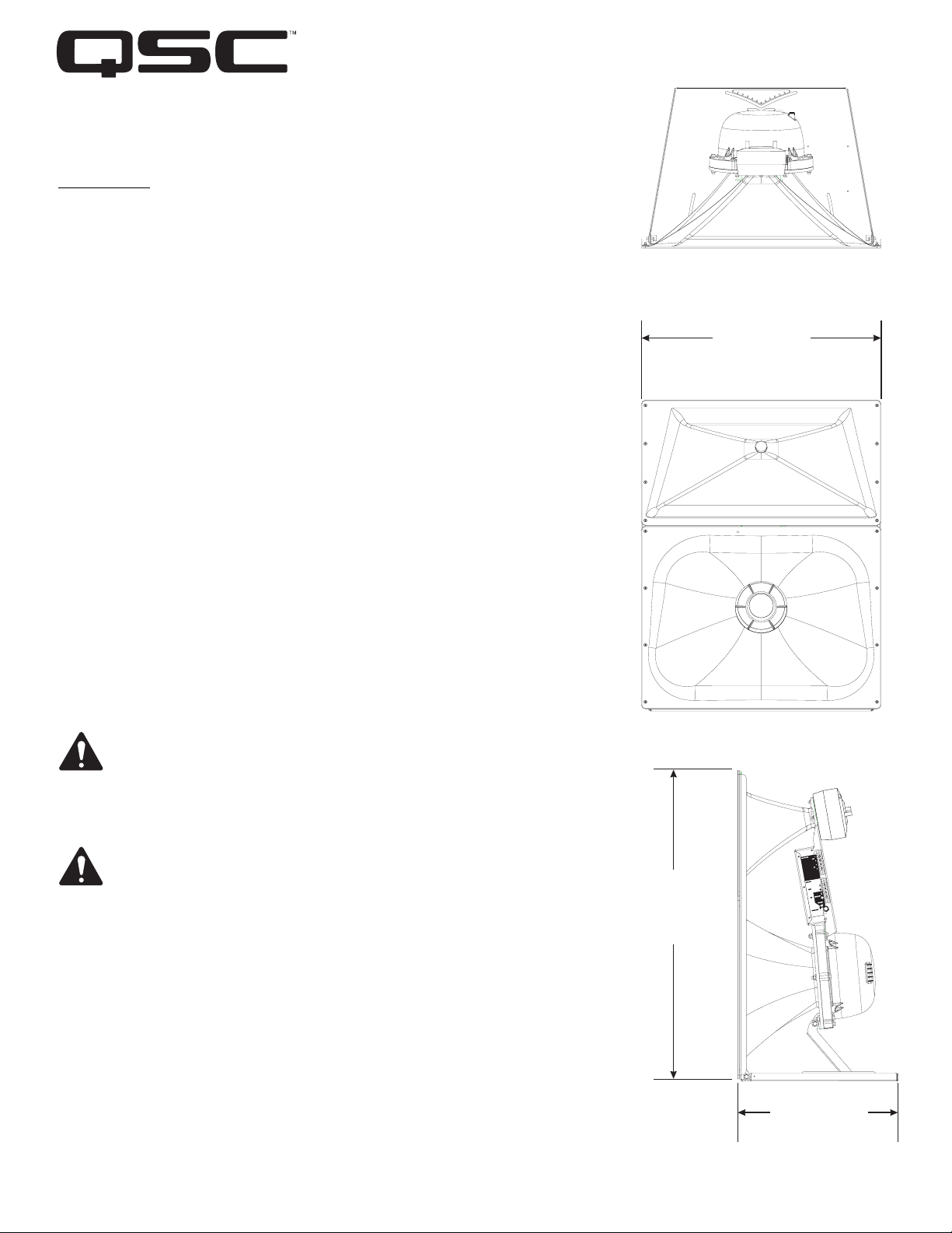
MHV-1090 10” (254mm) mid, coax high- very high compression driver
Introduction
The MHV-1090 system provides the mid, high, and very high frequency components of
four-way screen channel loudspeaker system for high performance cinema applications. It was designed to operate with and be directly mounted on QSC’s cinema low
frequency enclosures.
The high frequency horn is a low-distortion waveguide providing highly articulate dialogue without the coloration associated with conventional horn loudspeakers. Both
horns feature broad horizontal and vertical coverage to ensure audio integrity is delivered to every seat in the auditorium. The driver assemblies are mounted on an adjustable pan and tilt bracket that has an integral aiming sight, simplifying installation.
The MHV-1090 includes a driver protection and high-very high frequency crossover
network to assure reliable operation. DC blocking capacitors protect against DC or
low-frequency signals that could damage an unprotected driver. A 12 dB per octave
crossover seamlessly blends the high and very high frequency elements when operated in tri-amp mode. Outboard processing is required to form the crossover between
the low, mid, and high-very high frequency drivers.
30”
(762mm)
Tri-amp or quad-amp operation is possible using a selector switch mounted on the
INPUTS connection panel. The tri-amp setting provides a built-in passive crossover
network between high and very high frequency drivers. Separate amplifiers and active
crossovers are required for the low, mid, high-very high frequency channels. Quadamp setting disables the internal high-very high frequency crossover and each driver
is driven independently by its own amplifier and active crossover; one each required
for the low, mid, high, and very high frequency drivers.
The MHV-1090 components come pre-assembled to reduce field assembly time. Three
bolts are all that are required to secure the assembly to the top of a QSC low frequency enclosure.
Install in accordance with QSC Audio Product’s instructions and a
licensed, professional engineer. Only use attachments, mounts,
accessories, or brackets specified by QSC Audio Products, Inc. Refer
all servicing to qualified personnel. Servicing is required when the
apparatus has been damaged in any way.
WARNING! Before placing, installing, rigging, or suspending any
speaker product, inspect all hardware, suspension, enclosures,
transducers, brackets and associated equipment for damage. Any
missing, corroded, deformed or non-load rated component could significantly reduce the strength of the installation, placement, or array.
Any such condition severely reduces the safety of the installation and
should be immediately corrected. Use only hardware which is rated
for the loading conditions of the installation and any possible shortterm unexpected overloading. Never exceed the rating of the hardware or equipment. Consult a licensed, professional engineer when
any doubt or questions arise regarding a physical equipment installation.
39”
(991mm)
“QSC” and the QSC logo are registered with the U.S. Pat ent and Trademark Off ice
QSC® is a registered trademark of QSC Audio Products, Inc.
© Copyright 2007, QSC Audio Products, Inc.
TD-000246-00-A
20”
(508mm)
*TD-000246-00*
Mounting
Attaching to Low Frequency Enclosure
The MHV-1090 attaches to the top of QSC low frequency enclosures with three 0.75” long 5/16”-18 TPI bolts. ensure the use of lock washers on all bolts.
The bolts and washers ship installed on the low frequency enclosure. We recommend the use of serviceable thread locking compound when installing the
bolts to prevent loosening due to vibration. Do not fully tighten the mounting hardware before aiming in the horizontal plane (see below).
Aiming
Aim the horn in the horizontal plane (pan) before tightening the three bolts securing the MHV-1090 to the low frequency enclosure. Adjust the vertical tilt
with the vertical adjustment bracket. The mid-high assembly is equipped with an aiming sight to assist in achieving desired coverage quickly and easily.
For typical applications, the aim point should be the center seat in the back row of the auditorium. If the cinema screen has already been installed, a flashlight placed at the desired aiming point can be seen through the screen perforations in a darkened auditorium.
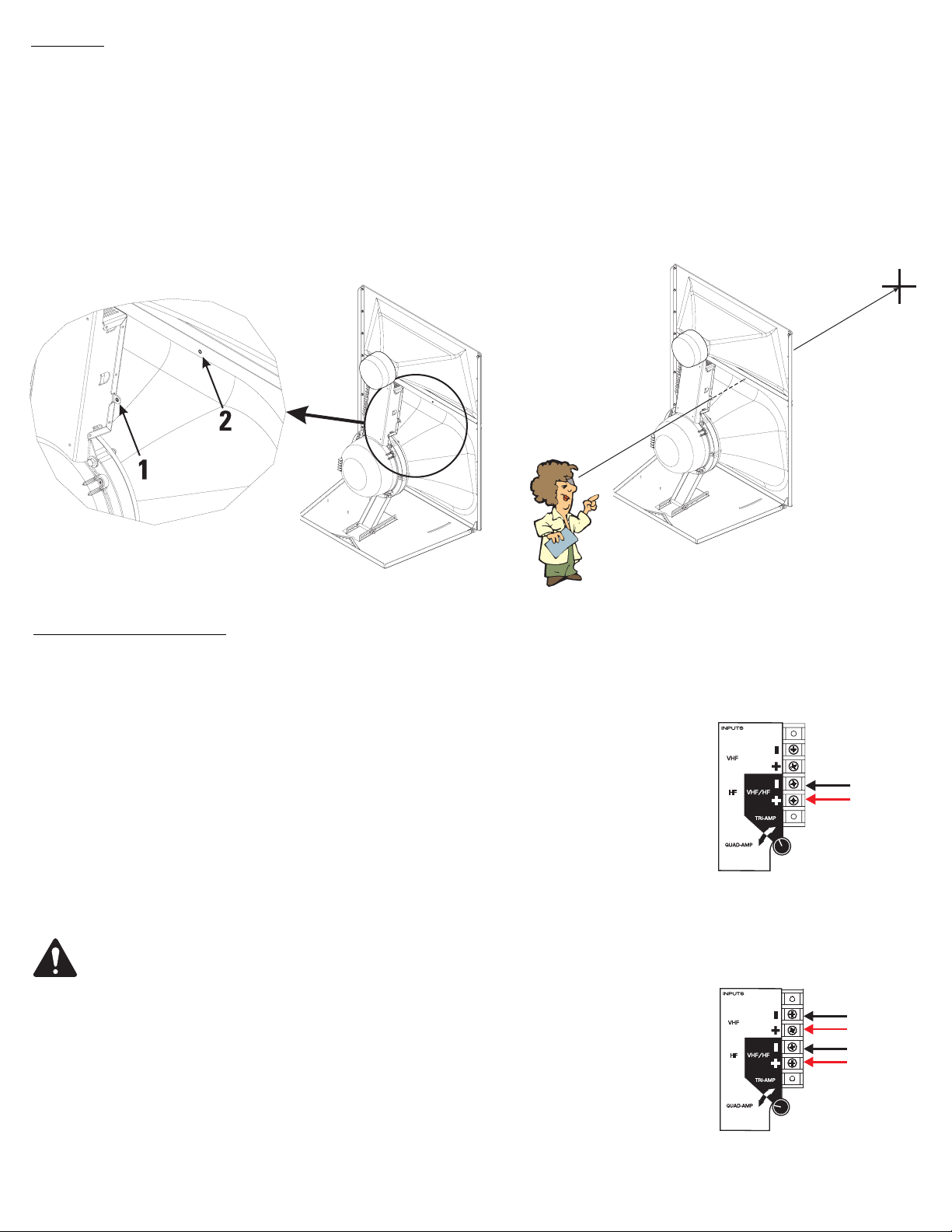
Where the sight holes are located:
How to use the sights:
Settings and Connections
TRI-AMP / QUAD-AMP Operating Mode Selection
Set the operating mode selector switch to TRI-AMP or QUAD-AMP, depending on your screen chan-
nel signal processing and amplification set-up. The mid frequency driver will require connection to its
rear cover terminals, regardless of mode selection. The low frequency driver will also require its own,
separate connections. The only connection difference between tri-amp and quad-amp modes is in
quad-amp mode, the very high frequency signal will require connection to the terminals labeled VHF.
Aim point:
Mode selector switch set to
TRI-AMP and the required
HF/VHF connection:
TRI-AMP-When set to TRI-AMP, the MHV-1090 input panel connections accept high frequency/very
high frequency signals on one set of inputs and uses an internal crossover network between the high
and very high frequency drivers.
QUAD-AMP- When set to QUAD-AMP, the MHV-1090 input panel accepts separate high and very
high frequency signals on two separate sets of inputs. The internal crossover network is bypassed and
only the protective circuitry for the high frequency and very high frequency driver remains. Each of the
driver’s signals must have the appropriate upstream signal processing.
•Do not connect amplifiers directly to the high/very high frequency coaxial driver
inputs!
• Always use the crossover INPUTS terminal strip for high and very high frequency
input(s)
•The mid frequency driver and the low frequency enclosure are connected directly
to their own separate amplifiers regardless of mode selector switch setting.
2
HF/VHF
Mode selector switch set to
QUAD-AMP and the required separate HF and VHF connections:
VHF
HF
INPUTS Terminals
The MHV-1090 has barrier strip screw terminals that accept up to #10 AWG (5.3mm
2
) stranded loudspeaker wire. Observe proper polarity. Use the
largest wire size and shortest wire length for the application.
OUTPUTS Terminals
The OUTPUT terminals are factory-connected to the high and very high frequency drivers. These terminals should ONLY be connected to their respec-
tive driver. Do not connect signals to these terminals as all protection and equalization circuitry will be bypassed. They are not for daisy chaining the
signals to other drivers.
NOTE! Maintain proper loudspeaker connection polarity throughout the entire system for maximum performance. Do not apply
full range signal to the MHV-1090! There is a high/very high frequency passive crossover for tri-amp mode only. There is no
crossover connected when operating in quad-amp mode. All required signal processing must be done before the signal is
applied to the loudspeaker. Do not connect any signal to the upper sets of OUTPUT terminals.
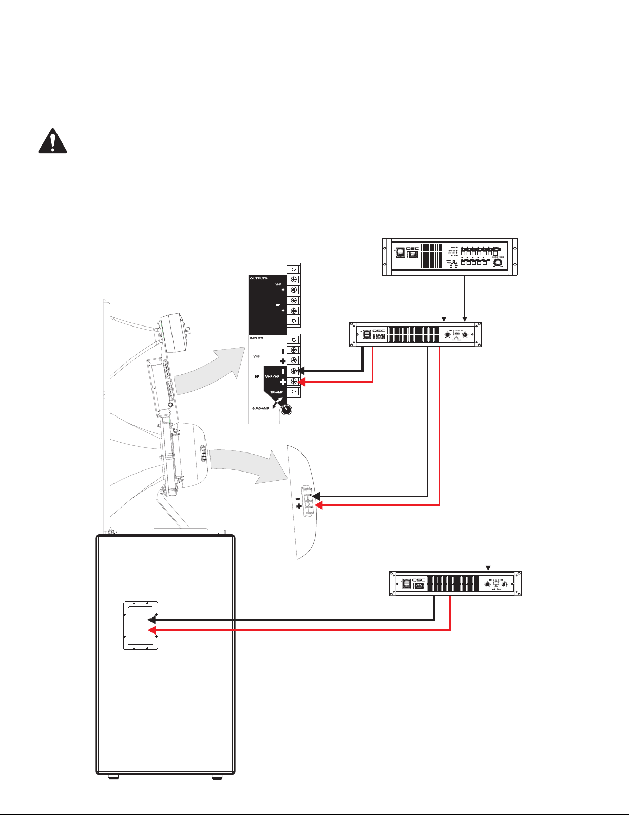
TRI-AMP mode connections- Ensure the mode selector switch is set to TRI-AMP, connect the low frequency signal to the low frequency enclosure;
connect the mid frequency signal to the mid frequency driver; connect the high/very high frequency signal to the VHF/HF terminals on the INPUTS terminal strip.
Signal Processing
MHV-1090
HF/VHF
Amplification
MF
Amplification
HF/VHF
MF
LF
Low Frequency Enclosure
LF
3
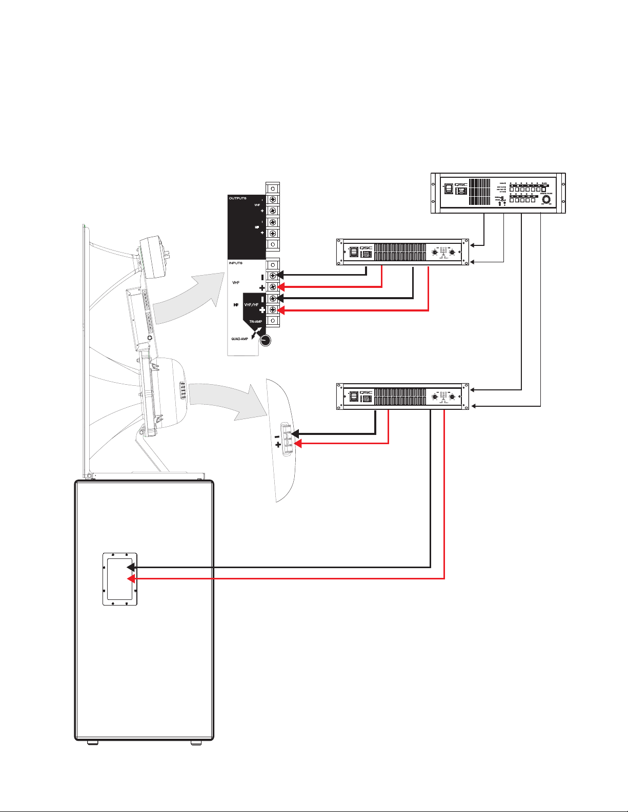
QUAD-AMP mode connections- Ensure the mode selector switch is set to QUAD-AMP, connect the low frequency signal to the low
frequency enclosure; connect the mid frequency signal to the mid frequency driver; connect the high frequency signal to the HF terminals on the INPUTS terminal strip; connect the very high frequency signal to the VHF terminals on the INPUTS terminal strip.
Signal Processing
MHV-1090
VHF
HF
MF
Amplification
Amplification
VHF
HF
MF
LF
LF
Low Frequency Enclosure
4
 Loading...