

QSC SC-433 Owners manual

Features
• Three-way selectable, bi or tri- amplified screen channel system
• MH-1075 provides 90° horizontal by +20° to -30° vertical coverage
• LF-4315 is constructed of MDF and features single woofer chambers
• Low-distortion waveguides provide highly articulate dialogue
SC-433
Cinema Loudspeaker System
• Shallow depth (20
™ approved for professional cinema applications
• THX
") facilitates installation
Developed specifically for the unique requirements
of professional motion picture playback, the SC-433
extends QSC’s commitment to the cinema market. As
a member of the DCS Digital Cinema Speaker Series,
the SC-433 is a three-way, selectable bi or tri-amplified
screen channel loudspeaker system comprised of two
main units—the MH-1075 high-frequency system and
the LF-4315 low-frequency system.
The MH-1075 mid-high system features a high
output, horn loaded 10" midrange cone driver and a
3" (75mm) titanium diaphragm compression driver
mounted to an adjustable pan and tilt bracket. The
MH-1075 includes a driver protection network and
a passive crossover for bi-amp operation. Power
limiter circuitry protects the high-frequency driver
from overpowering. The MH-1075 provides extended
frequency coverage for the critical midrange band. A
high power 10" cone driver allows operation as low
as 250 Hz and the advanced phase plug coupling
permits a crossover point of up to 1800 Hz to the
high-frequency horn. This ensures that most of the
dialog range is reproduced by a single element, for
unmatched intelligibility.
The LF-4315 triple 15" (381mm) low-frequency
enclosure is designed specifically to address the
extended low-frequency response required for cinema
applications. The LF-4315 covers the frequency range
from 35 Hz to 250 Hz. Close Coupled Woofers
(CCW), with their tight spacing between woofers,
improves coupling and keeps coverage angles wide
over a greater frequency range than more widely
spaced designs.
The SC-433 is designed for ease of installation.
The MH-1075 components come pre-assembled to
reduce field assembly time. Three bolts are all that
are required to secure the MH-1075 to the top of the
LF-4315 enclosure.
THX is a trademark of THX Ltd.
Specifications SC-433
Nominal Coverage 90° horizontal x +20 to -30° vertical
Frequency Range 32 Hz - 16 kHz (-6 dB)
Crossover Frequency 250 and 1700 Hz, 24 dB per octave
LF-4315 MH-1075
Impedance 5.5Ω 8Ω
Sensitivity 1 watt /1 meter, 99.5 dB Bi-amp Tri-amp
half space 105 dB MF 105 dB HF 107.5 dB
Maximum Input Power
8 hours of 6 db crest factor 1200 W RMS 250 W RMS2 275 W RMS 80 W RMS
IEC 268 noise spectrum
2 hours of 6 db crest factor 1500 W RMS 350 W RMS
pink noise, 50 Hz - 20 kHz,
AES method
Recommended Amplifier Power 2400 W RMS maximum 800 W RMS maximum
Recommended Processing Subsonic filter below 30 Hz, 4th order LR crossover at 200 and
> 18 dB per octave 1700 Hz via QSC DCM or QSControl.net
Connectors Barrier strip screw terminals Barrier strip screw terminals
Transducers Three 15" (381mm) high efficiency, 10" high efficiency mid range,
Enclosure Quasi B4 alignment, ported Tilt/Pan Bracket
Dimensions (HWD) 53" x 30" x 20.3" 39" x 30" x 20"
(1344 mm x 762 mm x 516 mm) (990 mm x 762 mm x 508 mm)
Weight - Net 260 lbs (118 kg) 85 lbs (39 kg)
System Weight 345 lbs (157 kg)
Baffle Cut-Out 93" x 32"
1) Maximum input power tested in accordance with IEC 268-5 recommendations, 50 Hz - 20 kHz band limiting, 6 dB signal crest factor.
2) Maximum input power tested in accordance with IEC 268-5 recommendations, 200 Hz - 2 kHz band limiting, 6 dB signal crest factor.
1
passive
mid-high
accept up to #10 AWG accept up to #10 AWG stranded wire
stranded wire
extended bass woofer featuring 1.5" (38mm) exit, 3" titanium
4" copper voice coils diaphragm compression driver
enclosure with fully flared ports, ±10° vertical tilt
symmetrical port design, tuned to ±10° horizontal pan
36 Hz, constructed of MDF and
heavily braced. Features vandal
resistant woofer mounting bolts
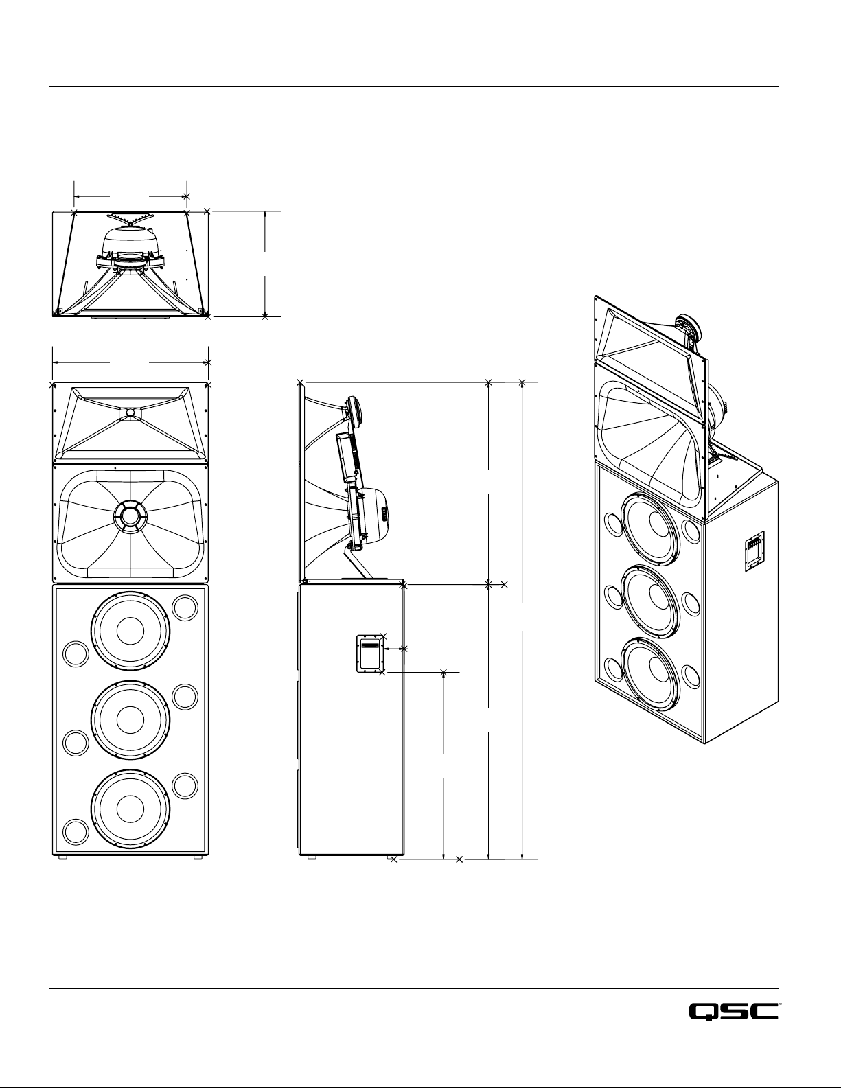
SC-433
Top
21.7"
551 mm
30"
762 mm
Dimensions
20.3"
516 mm
Side
39"
990 mm
92"
2337 mm
4"
102 mm
53"
1346 mm
36"
914 mm
Front
Specifications subject to change without notice.
1675 MacArthur Boulevard • Costa Mesa, CA 92626 • Ph: 800/854-4079 or 714/957-7100 • Fax: 714/754-6174
SC-433 Spec Sheet - 03/10/06
qscaudio.com

1675 MacArthur Blvd., Costa Mesa, CA, 92626 USA
Main Number (714) 754-6175 Sales & Marketing (714) 957-7100 or toll free (USA only) (800) 854-4079
Customer Service(714) 957-7150 or toll free (USA only) (800) 772-2834
Cinema Mid-High Loudspeaker System User Manual
MH-1063 10” (254mm) mid, 2.5” (63mm) compression driver
MH-1075 10” (254mm) mid, 3.0” (75mm) compression driver
Introduction
The MH-1063 and MH-1075 “mid-high packs” provide the mid and high frequency
components of three-way screen channel loudspeaker systems for high performance
cinema applications. They were designed to operate with and be directly mounted on
QSC’s cinema low frequency enclosures.
Mid frequencies are reproduced with a 10” (254mm) high-efficiency, phase-ring
loaded driver mounted on a custom designed cinema horn. The high-frequency driver
is a large format, 2.5” (63mm, MH-1063) or 3.0” (75mm, MH-1075) titanium diaphragm compression driver mounted on a custom high-frequency cinema horn. The
high frequency horn is a low-distortion waveguide providing highly articulate dialogue
without coloration associated with conventional horn loudspeakers. Both horns feature broad horizontal and vertical coverage angles to ensure coverage of every seat in
the auditorium. The driver assemblies are mounted on an adjustable pan and tilt
bracket that has an integral aiming sight, simplifying installation.
The MH-1063 and MH-1075 loudspeakers include a driver protection and crossover
network to assure reliable operation. DC blocking capacitors protect against DC or
low-frequency signals that could damage an unprotected driver. Power limiter circuitry
protects the driver from over-powering and an 18dB/octave crossover seamlessly
blends the high and mid frequency elements. Outboard processing is required to form
the crossover between the LF and MH loudspeakers.
Bi-amp or tri-amp operation is possible using a selector switch mounted on the connections panel. The bi-amp setting provides a passive crossover network between mid
and high drivers. Separate amplifiers and an active crossover are required for the low
frequency channel and the mid-high channel. Tri-amp setting disables the internal
mid-high crossover and each driver is driven independently by its own amplifier and
active crossover; one for the low, one for the mid, and one for the high frequencies.
The MH-1063 and MH-1075 components come pre-assembled to reduce field assembly time. Three bolts are all that are required to secure the mid-high assembly to the
top of a QSC low frequency enclosure.
Install in accordance with QSC Audio Product’s instructions and a
licensed, professional engineer. Only use attachments, mounts,
accessories, or brackets specified by QSC Audio Products, Inc. Refer
all servicing to qualified personnel. Servicing is required when the
apparatus has been damaged in any way.
WARNING! Before placing, installing, rigging, or suspending any
speaker product, inspect all hardware, suspension, cabinets, transducers, brackets and associated equipment for damage. Any missing,
corroded, deformed or non-load rated component could significantly
reduce the strength of the installation, placement, or array. Any such
condition severely reduces the safety of the installation and should
be immediately corrected. Use only hardware which is rated for the
loading conditions of the installation and any possible short-term
unexpected overloading. Never exceed the rating of the hardware or
equipment. Consult a licensed, professional engineer when any
doubt or questions arise regarding a physical equipment installation.
*TD-000180-00*
“QSC” and the QSC logo are registered with the U.S. Pa tent and Trademark Office
QSC® is a registered trademark of QSC Audio Products, Inc.
© Copyright 2004, QSC Audio Products, Inc.
TD-000180-00 rev.A

Mounting
Attaching to Low Frequency Enclosure
The mid-high loudspeaker assembly attaches to the top of the QSC low frequency cabinet with three 5/16-18 bolts, 0.75” long, with
lock washers. This hardware ships installed on the low frequency cabinet. We recommend the use of serviceable thread locking compound when installing the bolts to prevent loosening due to vibration. Do not fully tighten the mounting hardware before aiming (see
below).
Aiming
Aim the horn in the horizontal plane (pan) before tightening the attachment hardware. Adjust the vertical tilt with the mid-high vertical
adjustment bracket. The mid-high assembly is equipped with an aiming sight to assist in achieving desired coverage quickly and easily.
For typical applications, the aim point should be the center seat in the back row of the auditorium. If the cinema screen has already
been installed, a flashlight placed at the desired aiming point can be seen through the screen perforations in a darkened auditorium.
Where the sight holes are located:
How to use the sights:
Settings
BI-AMP / TRI-AMP Operating Mode Selection
Set the operating mode selector switch to BI-AMP or TRI-AMP, depending on your application setup.
Aim point:
BI-AMP-When set to BI-AMP, the MH-1063 and MH-1075 accepts mid-
high frequency signals on one set of inputs and uses an internal crossover
network between the mid- and high-frequency drivers. The signal applied
to the mid-high loudspeaker assembly must not contain low-frequency
content (below 200 Hz).
TRI-AMP- When set to TRI-AMP, the MH-1063 and MH-1075 accepts
separate mid- and high-frequency signals on two sets of inputs. The internal crossover network is bypassed and only the protective circuitry for the
H.F. driver remains. Each of the driver’s signals must have the appropriate
signal processing before operating.
Do not connect amplifiers directly to the driver inputs!
Always use the input terminal strip.
2

Connections
INPUT Terminals
The MH-1063 and MH-1075 have barrier strip screw terminals that accept up to #10 AWG (5.3mm
Observe proper polarity. Use the largest wire size and shortest wire length for the application.
OUTPUT Terminals
The OUTPUT terminals are factory-connected to the drivers. These terminals should ONLY be connected to their respective driver. Do
not connect signals to these terminals as all protection and equalization circuitry will be bypassed.
NOTE! Maintain proper loudspeaker connection polarity throughout the entire system for maximum performance.
Do not apply full range signal to the MH-1063 / MH-1075! There is a mid-high passive crossover for bi-amp mode
only. There is no crossover connected when operating in tri-amp mode. A protection network is always active. All
required signal processing must be done before the signal is applied to the loudspeaker. Do not connect any signal to the upper sets of OUTPUT terminals.
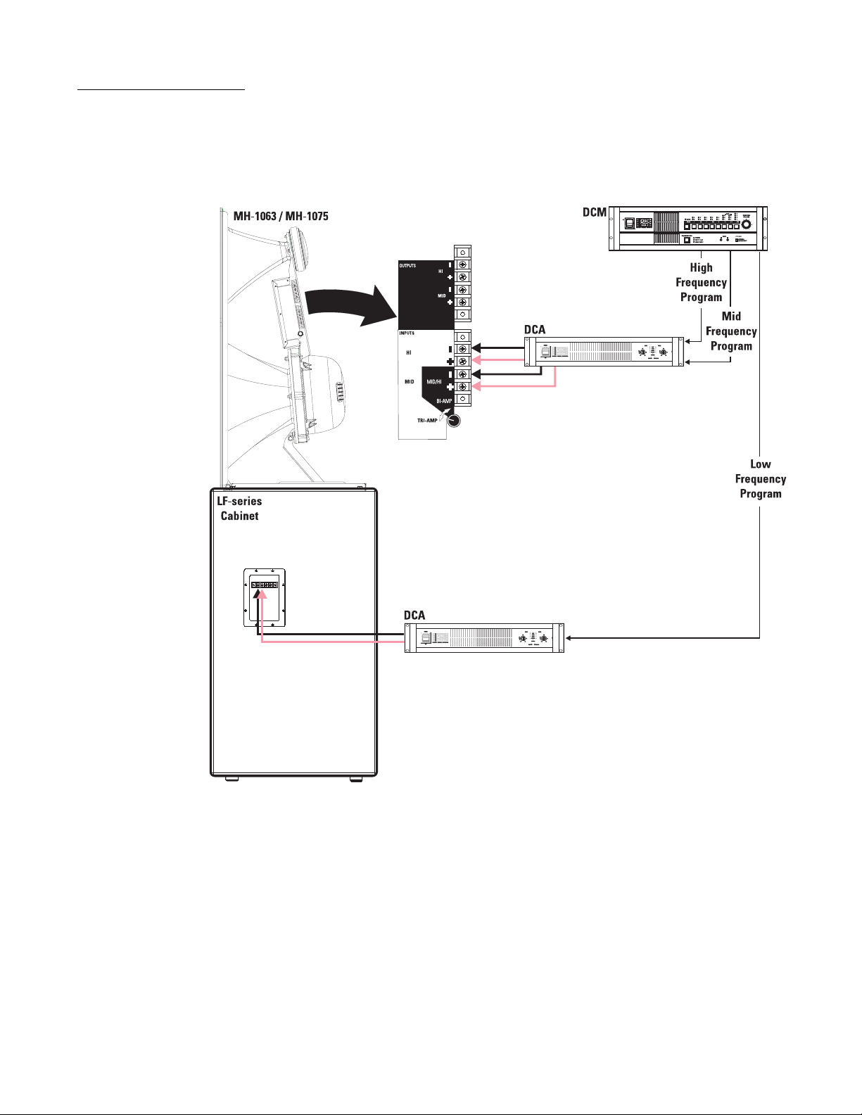
BI-AMP mode connections- Ensure the mode switch is set to BI-AMP, connect the input to the MH-1063 / MH-1075 to the lower
set of input terminals marked “BI-AMP + -”.
BI-AMP Mode- one
amplifier channel is used
for the low frequency
cabinet and one amplifier
channel for the mid-high
assembly. The MH-1063 /
MH-1075 mode switch is
set to BI-AMP. Active
crossovers are used
before amplification. The
mid-high assembly provides a passive crossover
between the mid and
high frequency drivers.
2
) stranded loudspeaker wire.
3
Connections (continued)
TRI-AMP mode connections- When the mode switch is set to TRI-AMP, connect the high frequency signal to the terminals marked
“INPUT HI + -” and the mid frequency signal to the terminals marked “INPUT MID + -”.
TRI-AMP Mode- one
amplifier channel is
used for the low frequency cabinet, one
amplifier channel for
the mids, and one
amplifier channel for
the high frequencies.
The MH-1063 / MH1075 mode switch is
set to TRI-AMP,
bypassing the internal
mid-high passive crossover. Active or passive
crossovers are used
before amplification.
Power limiter and DC
blocking remain active.
4

MH-1063 Specifications (subject to change without notice)
Freq. Range 180 - 15k (-6dB, full space)
Nominal Coverage 90° horizontal X +20 to -30° vertical (50° total, adjustable mount provides for vertical plane adjustments.
The horizontal plane can be adjusted by altering mounting position on the low frequency enclosure before
tightening bolts.
DI: 9 dB (400 to 16k Hertz average)
Q: 8 (400 to 16k Hertz average)
Max. Output: [Tri-amp mode] Mid Freq. 135.5 dB SPL calculated peak, 1m, full space
[Tri-amp mode] High Freq. 131.5 dB SPL calculated peak, 1m, full space
[Bi-amp mode] 135 dB SPL calculated peak, 1m ,full space
Impedance: [Bi-amp mode] 8 ohms nominal
7.9 ohms minimum at 1500 Hertz
91 ohms maximum at 150 Hertz
Maximum Input Power [Tri-amp mode] Mid Freq. 275 W (AES method, 2 hrs.)
[Tri-amp mode] High Freq. 60 W (AES method, 2 hrs.)
[Bi-amp mode] 250 W (IEC method, 8 hrs.)
Sensitivity [Tri-amp mode] Mid Freq. 105 dB SPL, 1 watt, 1 meter
[Tri-amp mode] High Freq. 107.5 dB SPL, 1 watt, 1 meter
[Bi-amp mode] 135 dB SPL, 1 watt, 1 meter
Crossover Frequency [Tri-amp mode] 250 Hertz or higher, 24dB/octave and 1.7k Hertz, 24dB/octave
[Bi-amp mode] 250 Hertz or higher, 24dB/octave
Crossover Network 1.7k Hertz, 18 dB/octave electrical slope, HF driver power limiting circuit (never disrupts continuity). Swit-
chable operation between Bi-Amp and Tri-amp operation. Tri-amp setting removes crossover circuit from
signal, leaving power limiter and DC blocking capacitors.
Connectors Barrier strip screw terminals accept up to #10 AWG stranded wire. Four terminals, two HF input and two
MF input (for Tri-amp mode operation).
Transducers MF: 10" high efficiency midrange, phase-ring loaded.
HF: 1.5" (38mm) exit, 2.5" (63.5mm) titanium diaphragm compression driver.
Mounting Hardware: Attaches to top of the low frequency cabinet using three 5/16”-18 x 3/4” long bolts.
Size 39” high x 30” wide x 20” deep (991 x 762 x 508mm)
Weight 85 lb. (39 kg) net
5

MH-1075 Specifications (subject to change without notice
Freq. Range 180 - 15k (-6dB, full space)
Nominal Coverage 90° horizontal X +20 to -30° vertical (50° total, adjustable mount provides for vertical plane adjustments.
The horizontal plane can be adjusted by altering mounting position on the low frequency enclosure before
tightening bolts.
DI: 9 dB (400 to 16k Hertz average)
Q: 8 (400 to 16k Hertz average)
Max. Output: [Tri-amp mode] Mid Freq. 135.5 dB SPL calculated peak, 1m, full space
[Tri-amp mode] High Freq. 133 dB SPL calculated peak, 1m, full space
[Bi-amp mode] 135.5 dB SPL calculated peak, 1m ,full space
Impedance: [Bi-amp mode] 8 ohms nominal
6.4 ohms minimum at 1500 Hertz
91 ohms maximum at 150 Hertz
Maximum Input Power [Tri-amp mode] Mid Freq. 275 W (AES method, 2 hrs.)
[Tri-amp ode] High Freq. 80 W (AES method, 2 hrs.)
[Bi-amp mode] 250 W (IEC method, 8 hrs.)
Sensitivity [Tri-amp mode] Mid Freq. 105 dB SPL, 1 watt, 1 meter
[Tri-amp mode] High Freq. 108 dB SPL, 1 watt, 1 meter
[Bi-amp mode] 135.5 dB SPL, 1 watt, 1 meter
Crossover Frequencies [Tri-amp mode] 250 Hertz or higher, 24dB/octave and 1.7k Hertz, 24dB/octave
[Bi-amp mode] 250 Hertz or higher, 24dB/octave
Crossover Network 1.7k Hertz, 18 dB/octave electrical slope, HF driver power limiting circuit (never disrupts continuity). Swit-
chable operation between Bi-Amp and Tri-amp operation. Tri-amp setting removes crossover circuit from
signal, leaving power limiter and DC blocking capacitors.
Connectors Barrier strip screw terminals accept up to #10 AWG stranded wire. Four terminals, two HF input and two
MF input (for Tri-amp mode operation).
Transducers MF: 10" high efficiency midrange, phase-ring loaded.
HF: 1.5" (38mm) exit, 3" (76mm) titanium diaphragm compression driver.
Mounting Hardware: Attaches to top of the low frequency cabinet using three 5/16”-18 x 3/4” long bolts.
Size 39” high x 30” wide x 20” deep (991 x 762 x 508mm)
Weight 85 lb. (39 kg) net
6

MH-1063 SPL and Impedance vs. Frequency
SPL
SPL (dB)
Impedance
Impedance (Ohms)
Frequency (Hertz)
MH-1075 SPL and Impedance vs. Frequency
SPL
SPL (dB)
Impedance
Impedance (Ohms)
Frequency (Hertz)
7
 Loading...