

Quick Start Guide

Array Frame and Stack Adapter Kits for LA108 and LA112 Active Line Array Loudspeakers
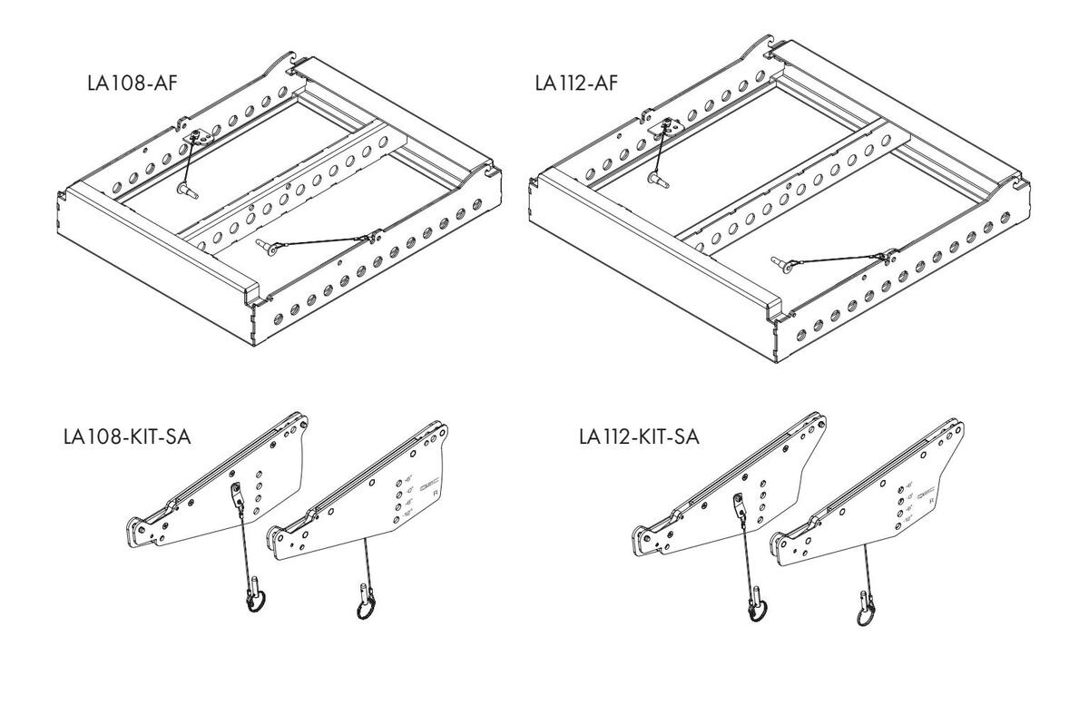
LA108-AF: Array Frame for the LA108 Active Line Array Loudspeaker
LA 112-AF: Array Frame for LA 112 Active Line Array Loudspeaker
LA108-KIT-SA: Stack Adapter Kit (to be combined with LA108-AF)
LA112-KIT-SA: Stack Adapter Kit (to be combined with LA112-AF)

TD-001647-01-B


IMPORTANT SAFETY INSTRUCTIONS


WARNING!: Before placing, installing, rigging, or suspending any loudspeaker product, inspect all hardware, suspension, cabinets, transducers, brackets and associated equipment for damage. Any missing, corroded, deformed, or non-load rated component could significantly reduce the strength of the installation or placement. Any such condition severely reduces the safety of the installation and should be immediately corrected. Use only hardware which is rated for the loading conditions of the installation and any possible short-term, unexpected overloading.
Never exceed the rating of the hardware or equipment.
Consult a licensed, professional engineer regarding physical equipment installation. Ensure that all local, state and national regulations regarding the safety and operation of loudspeakers and related equipment are understood and adhered to.
Rigging Safety Regulations:
- 2006/42/EC
- EN ISO 12100-1: 2004
- EN1991-1 / EN1993-1-1 / EN1993-1-8 / EN1999-1-1
- DGUV Vorschrift 17/18
- ANSI E1.8-2018
General Rules for Suspension
- Consult a professional mechanical or structural engineer, licensed in the jurisdiction of the sound system installation, to review, verify, and approve all attachments to the building or structure.
- Employ the services of a certified, professional rigger for hoisting, positioning, and attaching the equipment to the supporting structure.
- Correct use of all suspension hardware and components is imperative in sound system suspension and deployment.
- Always calculate suspended loads before lifting to make sure suspension components and hardware are used within their respective load limits.
- Consult local codes and regulations to fully understand the requirements for suspended loads in the venue in which the equipment will be suspended.
- Use only dedicated QSC LA108-AF and/or QSC LA112-AF Array Frames or the QSC LA-KIT-I installation kit (sold separately) for suspending a loudspeaker array.
- Be absolutely certain of the integrity of any structural member intended to support suspended loads. Hidden structural members can have hidden structural weakness.
- Never assume anything! Owner or third-party supplied suspension attachment points may not be adequate for suspending the loads.
- Before lifting, always inspect all components (enclosures, suspension brackets, pins, frames, bolts, nuts, slings, shackles, etc.) for cracks, wear, deformation, corrosion, missing, loose, or damaged parts that could reduce the strength of the assembly. Discard any worn, defective, or suspect parts and replace them with new, appropriately load-rated parts.
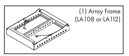
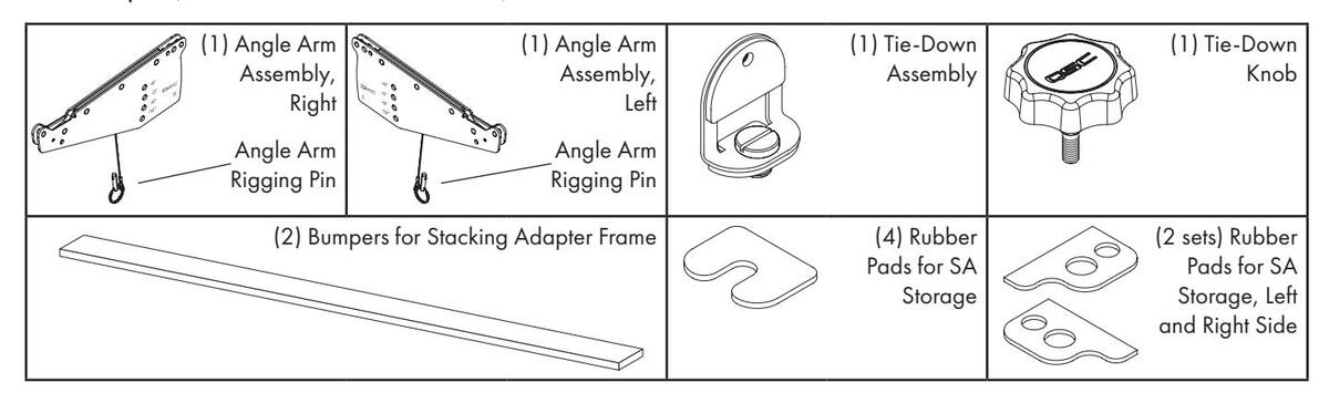
What's in the box
Array Frame (LA108 or LA112)
Stack Adapter (LA108-KIT-SA or LA112-KIT-SA)
Flown Deployment
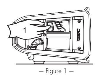
Array Frame Attachment Preparation
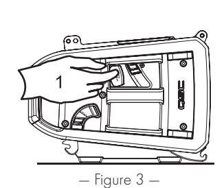
- 1. Push Angle Levers on both sides all the way in, until they make a click sound and stay depressed. (See Figure 1 –)
- 2. Push Angle Bar Lift up on both sides, until they make a click sound and the Angle Bar is at the 6° setting. (See Figure 2 –)
- 3. Repeat steps 1 and 2 to raise Angle Bar to the 1.5° setting. (See Figure 3 and Figure 4 –)
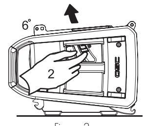
— Figure 2 —
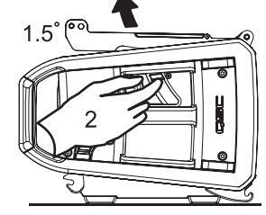
— Figure 4 —
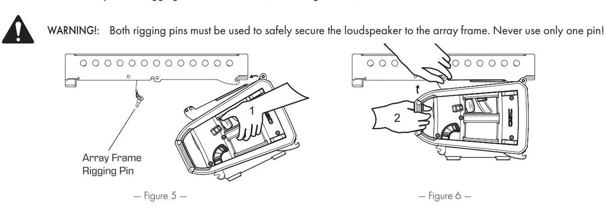
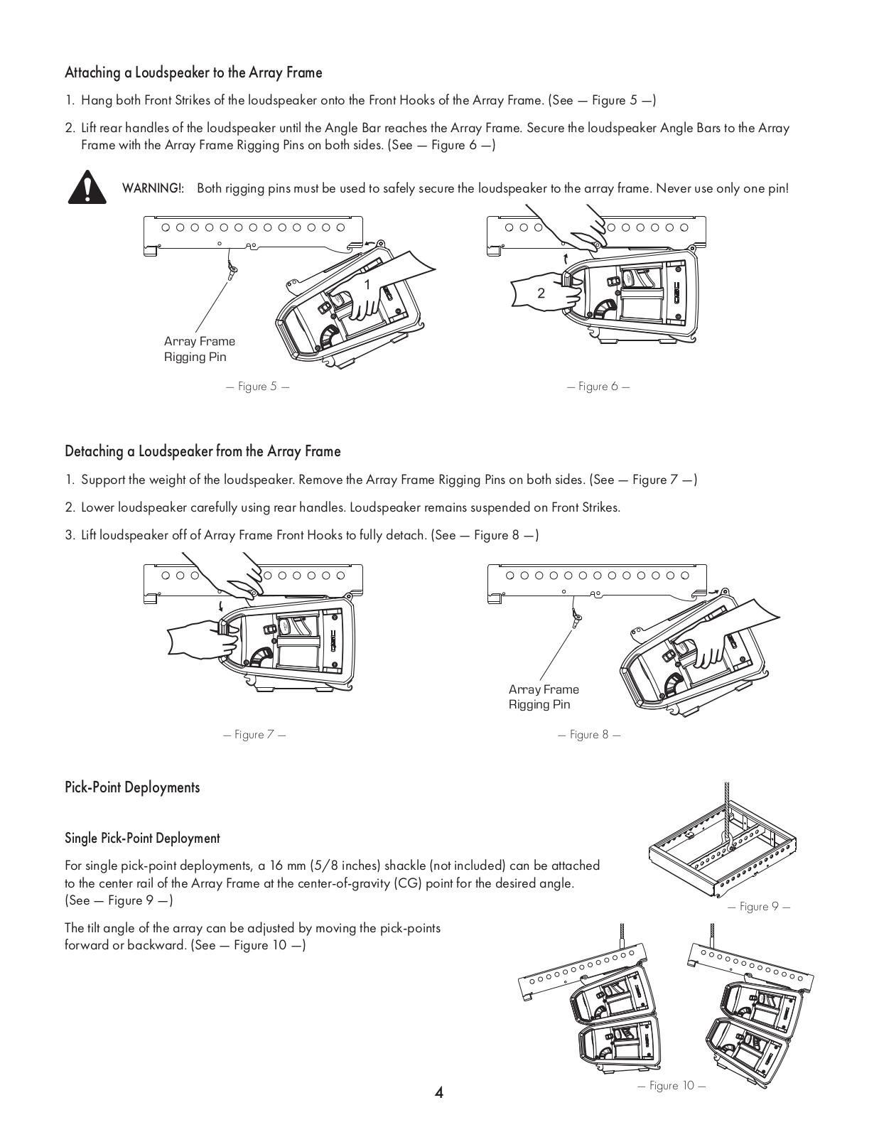
Attaching a Loudspeaker to the Array Frame
- 1. Hang both Front Strikes of the loudspeaker onto the Front Hooks of the Array Frame. (See Figure 5 –)
- 2. Lift rear handles of the loudspeaker until the Angle Bar reaches the Array Frame. Secure the loudspeaker Angle Bars to the Array Frame with the Array Frame Rigging Pins on both sides. (See Figure 6 –)
Detaching a Loudspeaker from the Array Frame
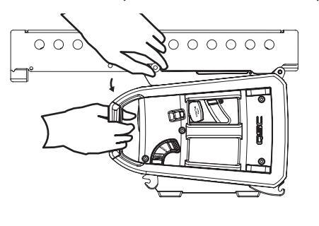
- 1. Support the weight of the loudspeaker. Remove the Array Frame Rigging Pins on both sides. (See Figure 7 –)
- 2. Lower loudspeaker carefully using rear handles. Loudspeaker remains suspended on Front Strikes.
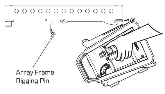
- 3. Lift loudspeaker off of Array Frame Front Hooks to fully detach. (See Figure 8 -)

Pick-Point Deployments
Single Pick-Point Deployment
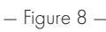
For single pick-point deployments, a 16 mm (5/8 inches) shackle (not included) can be attached to the center rail of the Array Frame at the center-of-gravity (CG) point for the desired angle. (See — Figure 9 —)
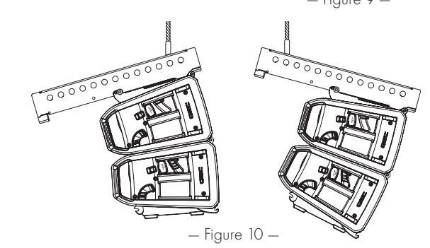
The tilt angle of the array can be adjusted by moving the pick-points forward or backward. (See – Figure 10 –)
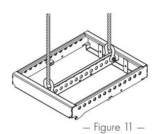
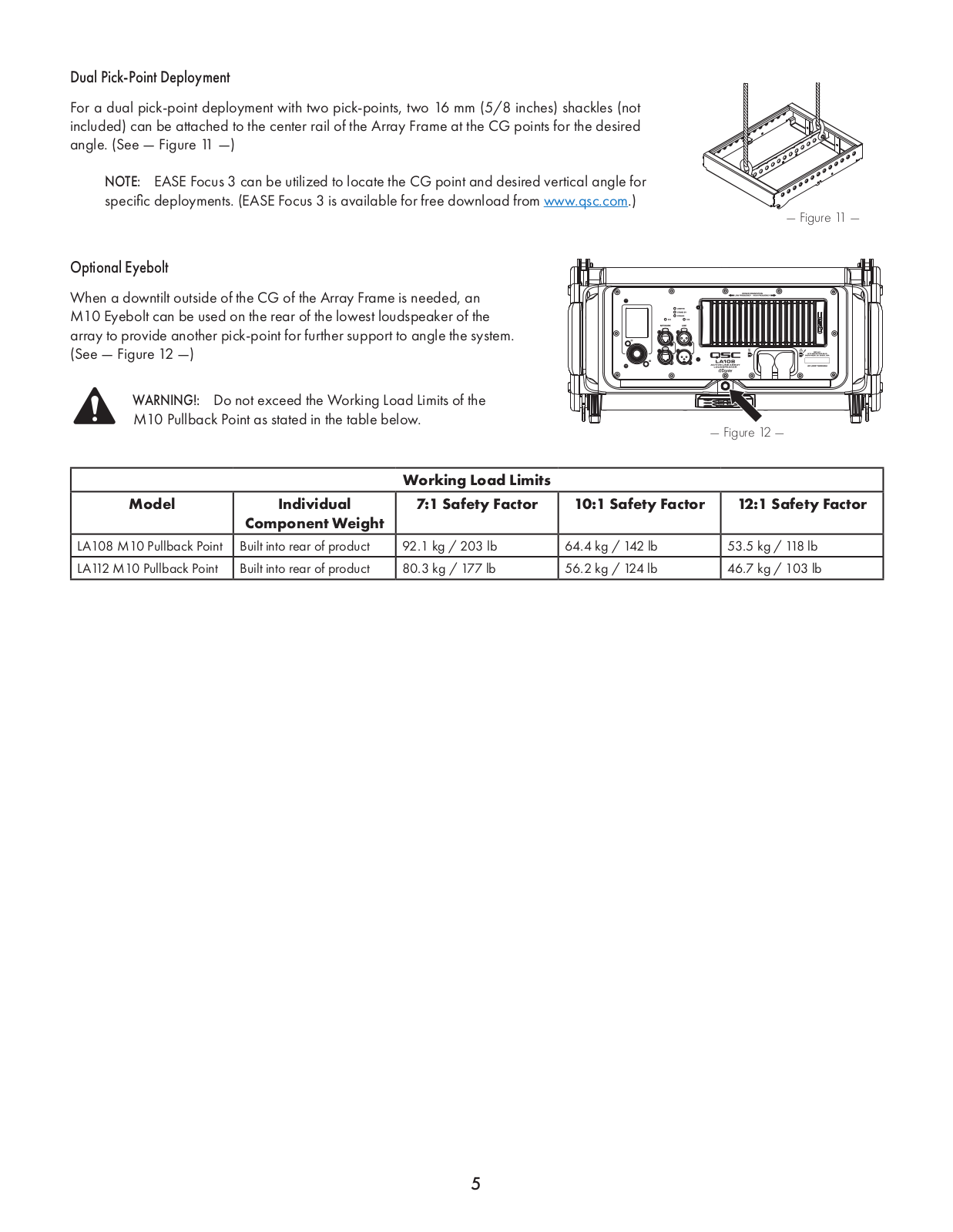
Dual Pick-Point Deployment
For a dual pick-point deployment with two pick-points, two 16 mm (5/8 inches) shackles (not included) can be attached to the center rail of the Array Frame at the CG points for the desired angle. (See — Figure 11 —)
NOTE: FASE Focus 3 can be utilized to locate the CG point and desired vertical angle for specific deployments. (EASE Focus 3 is available for free download from www.gsc.com.)
Optional Evebolt
When a downtilt outside of the CG of the Array Frame is needed an M10 Eyebolt can be used on the rear of the lowest loudspeaker of the array to provide another pick-point for further support to anale the system. (See — Figure 12 —)


WARNING!: Do not exceed the Working Load Limits of the M10 Pullback Point as stated in the table below.
| Working Load Limits | ||||
|---|---|---|---|---|
| Model |
Individual
Component Weight |
7:1 Safety Factor | 10:1 Safety Factor | 12:1 Safety Factor |
| LA108 M10 Pullback Point | Built into rear of product | 92.1 kg / 203 lb | 64.4 kg / 142 lb | 53.5 kg / 118 lb |
| LA 112 M 10 Pullback Point | Built into rear of product | 80.3 kg / 177 lb | 56.2 kg / 124 lb | 46.7 kg / 103 lb |
Ground Deployment
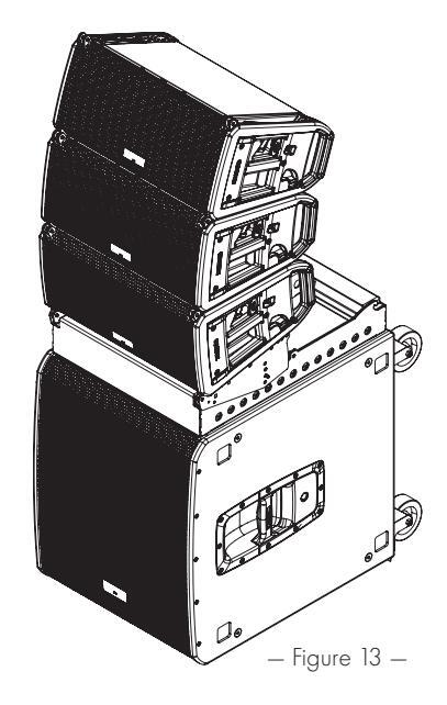
Stacking over a Subwoofer(s)
LA108/LA112 active line array loudspeakers offer the ability to safely stack an array over an LS118/KS118 subwoofer(s) unit using the appropriate Array Frame and Sub Stack Adapter Kit (sold separately).

WARNINGI: When deploying loudspeakers on subwoofers, attention should be given to environmental conditions such as level surfaces, vibrations, wind, etc. to deploy the loudspeakers in a stable and safe manner. Use additional measures to secure the subwoofer (hardware not included with subwoofer) when necessary.
LA108
An array of up to four (4) LA108 loudspeakers can be stacked over one (1) LS118/KS118 subwoofer when the subwoofer is upright, or two (2) LS118/KS212C subwoofers when rotated on their side.
LA 112
An array of up to three (3) LA 112 loudspeakers can be stacked over one (1) or two (2) LS 118/KS212C when the subwoofers are rotated on their side.
NOTE: For these ground-stack deployments, the LA108-AF (Array Frame) and the LA108-KIT-SA (Stack Adapter Kit) accessories (sold separately), or the LA112-AF (Array Frame) and the LA112-KIT-SA (Stack Adapter Kit) accessories (sold separately) are needed on the top (LS118/KS118/KS212C) or side (LS118/KS212C) of the subwoofer to secure the array. These combined accessories bolt onto the M20 thread located on the top or side of the subwoofer (LS118/KS212C) to secure the array. See next section for proper deployment of these two accessories, please refer to the individual accessories' user manuals.
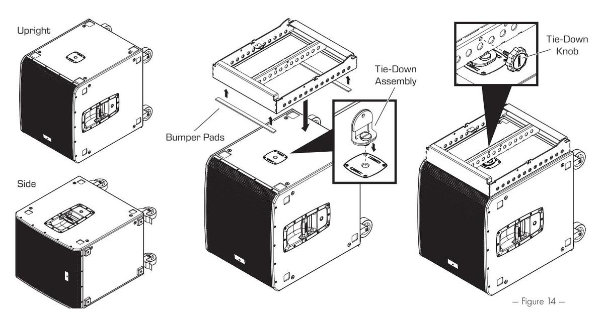
Attaching an Array Frame and Stack Adapter Kit to a Subwoofer
See – Figure 14 – for steps 1 to 4.
- 1. Carefully remove paper backing from the adhesive sides of the Bumper Pads. Adhere Bumper Pads to the bottom of the Array Frame as shown.
- 2. Secure the Tie-Down Assembly to the M20 thread located on top, or side, of the subwoofer enclosure. Tighten screw with fingers until snug. If necessary, tighten further using a coin, a key, or a large screwdriver.
- 3. Place Array Frame on subwoofer with the Bumper Pads facing downward.
- 4. Use the Tie-Down Knob to secure the Array Frame to the Tie-Down Assembly. Tighten the knob with your hand until snug. Array Frame is now secured to the subwoofer.
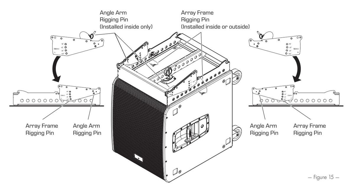
- 5. Attach the front end of each Angle Arm (part of the Stack Adapter Kit, sold separately) to each side of the Array Frame. Secure each side with the Angle Arm Rigging Pins. (See Figure 15 —)
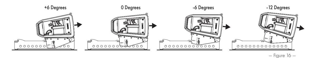
- 6. Adjust the Angle Arms to the desired angle. Secure each with the Array Frame Rigging Pins. (See Figure 16 -)
Attaching a Loudspeaker to a Subwoofer
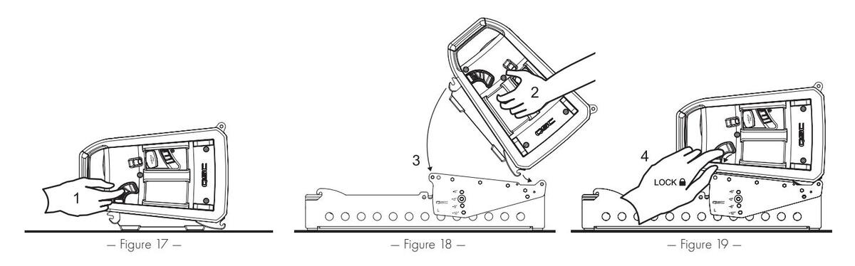
- 1. After securing the Array Frame and Stack Adapter Kit to the subwoofer, set the Locking Levers on both sides of the loudspeaker to the middle (ADD+) position. (See Figure 17 –)
- 2. Hook both Front Strikes of the loudspeaker onto the Front Hooks of the Array Frame. (See Figure 18 –)
- 3. Lower the back side of the loudspeaker until the Angle Arm latches onto the Rear Hook of the loudspeaker on both sides, making a click sound. (See Figure 18 –)
- 4. Push Locking Levers down (LOCK) to secure loudspeaker on both sides. (See Figure 19 -)
Detaching a Loudspeaker from a Subwoofer
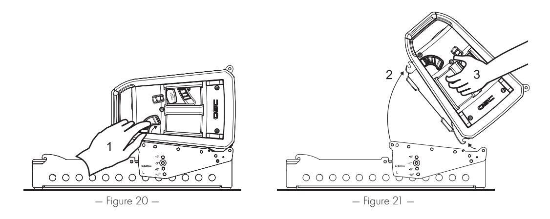
- 1. Set the Locking Levers on both sides of the loudspeaker to the up (REMOVE) position. (See Figure 20 -)
- 2. Lift backside of the loudspeaker away from the Angle Arms.
- 3. Lift loudspeaker off of Array Frame Front Hooks to fully detach. (See Figure 21 -)
Stack Adapter Kit Storage
- 1. Stack Adapter Kits may be configured for storage inside of the Array Frame when not in use.
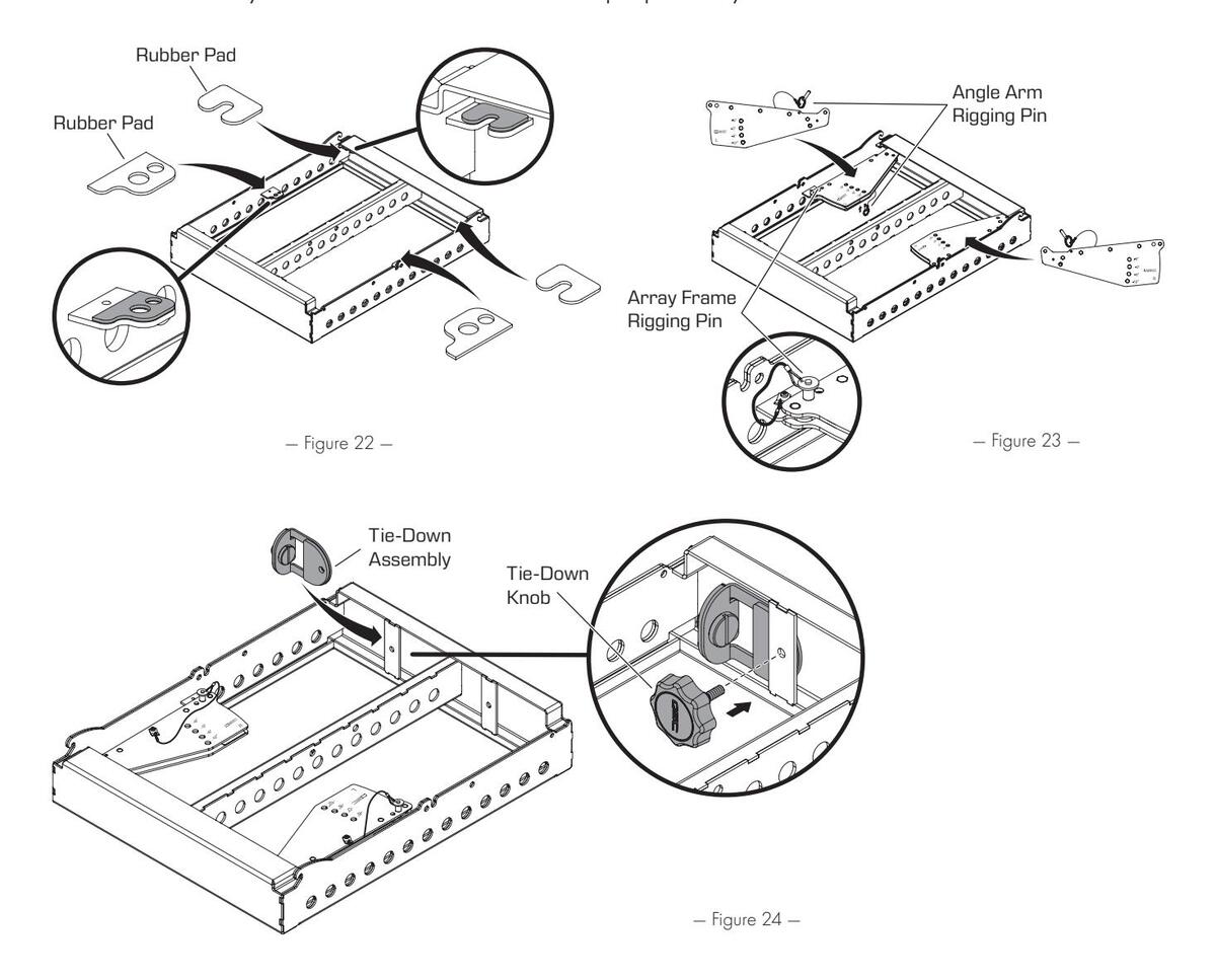
- 2. Carefully remove paper backing from the adhesive sides of the rubber pads. Adhere rubber pads to the Array Frame as shown. (See - Figure 22 -)
- 3. Store the Angle Arms from the Stack Adapter Kit inside the Array Frame using the Angle Arm Rigging Pins and the Array Frame Rigging Pins to secure them in place. (See Figure 23 –)
- 4. Store the Tie-Down Assembly using the Tie-Down Knob in one of the two designated locations as shown. (See Figure 24 -)
NOTE: Array Frame can be flown with Sub Stack Adapter parts safely stored as instructed.

Self Help Portal
Read knowledge base articles and discussions, download software and firmware, view product documents and training videos, and create support cases. Go to ascprod.force.com/selfhelpportal/s/.
Customer Support
Refer to the Contact Us page on the QSC website for Technical Support and Customer Care, including their phone numbers and hours of operation. Go to gsc.com/contact-us/.
Warranty
For a copy of the QSC Limited Warranty, go to qsc.com/support/warranty-statement/.


 Loading...