

QSC HPR-181-I Owners manual
1675 MacArthur Blvd., Costa Mesa, CA, 92626 USA
Main Number (714) 754-6175 or toll free (USA only) (800) 854-4079
Customer Service(714) 957-7150 or toll free (USA only) (800) 772-2834
HPR Series Powered Loudspeaker Products
User Manual Manual del usuario Manuel d'utilisation Benutzerhandbuch
HPR122i 12-inch two-way
HPR152i 15-inch two-way
HPR153i 15-inch three-way
HPR151i 15-inch subwoofer
HPR181i 18-inch subwoofer
用户手册
*TD-000234-00*
RM-000008-GPrev B (TD-000234-00 rev.C)
Important Safety Precautions & Explanation of Symbols
Install in accordance with QSC Audio Product's instructions and under the supervision of a licensed Professional Engineer.
WARNING!
CAUTION: TO REDUCE THE RISK OF ELECTRIC SHOCK, DO NOT REMOVE THE COVER.
NO USER-SERVICEABLE PARTS INSIDE. REFER SERVICING TO QUALIFIED PERSONNEL.
The lightning flash with arrowhead symbol within an equilateral triangle is intended to alert the user to the presence of uninsulated “dangerous” voltage within the product's enclosure that may be of sufficient magnitude to
constitute a risk of electric shock to humans.
The exclamation point within an equilateral triangle is intended to alert the user to the presence of important
operating and maintenance (servicing) instructions in this manual.
1- Read these instructions.
2- Keep these instructions.
3- Heed all warnings.
4- Follow all instructions.
5- WARNING: To prevent fire or electric shock, do not expose this equipment to rain or moisture. Do not use this apparatus near water.
6- Clean only with a dry cloth.
7- Allow a minimum of 6” (152mm) clearance at cabinet back for convection cooling. Keep anyt hing that might restrict airflow away from the rear of the enclosure
(i.e draperies, fabric, etc...). Do not block any ventilation openings. This product contains an internal power amplifier that produces heat.
8- Do not install near any heat sources such as radiators, heat registers, stoves, or other apparatus (including amplifiers) that produce heat.
9- Do not defeat the safety purpose of the grounding-type plug. The grounding plug has two blades and a grounding prong. The third prong is provided for your
safety. If the provided plug does not fit your outlet, consult an electrician for the replacement of the obsolete outlet. Do not cut off the grounding prong or use an
adapter that breaks the grounding circuit. This apparatus must be properly grounded for your safety.
10- Protect the power cord from being walked on or pinched, particularly plugs, convenience receptacles, and the point where they exit from the apparatus.
11- This product is not equipped with an all-pole mains switch. To fully disconnect from the AC mains, the AC plug must be removed from the AC outlet or the
appliance coupler (IEC block) must be removed from the amplifier module. Ensure either the AC line cord plug or the appliance coupler are accessible in case
of emergency disconnect requirement.
12- Use only attachments/accessories specified by QSC Audio Products, Inc.
13- Use only with hardware, brackets, stands, and components sold with the apparatus or by QSC Audio Products, Inc.
14- Unplug the apparatus during lightning storms or when unused for long periods of time.
15- Refer all servicing to qualified service personnel. Servicing is required when the apparatus has been damaged in any way, such as power supply cord or
plug is damaged, liquid has been spilled or objects ha ve fallen into the apparatus, the apparatus has been exposed to rain or moisture, does not operate normally,
or has been dropped.
16- Before placing, installing, rigging, or suspending any speaker product, inspect all hardware, suspension, cabinets, transducers, brackets and associated
equipment for damage. Any missing, corroded, deformed, or non-load rated component could significantly reduce the strength of the installation or placement.
Any such condition severely reduces the safety of the installation and should be immediately corrected. Use only hardware which is rated for the loading conditions of the installation and any possible short-term, unexpected overloading. Never exceed the rating of the hardware or equipment.
17- Consult a licensed, Professional Engineer regarding physical equipment installation. All local, state and national regulations regarding the safety and operation of equipment are understood and adhered to.
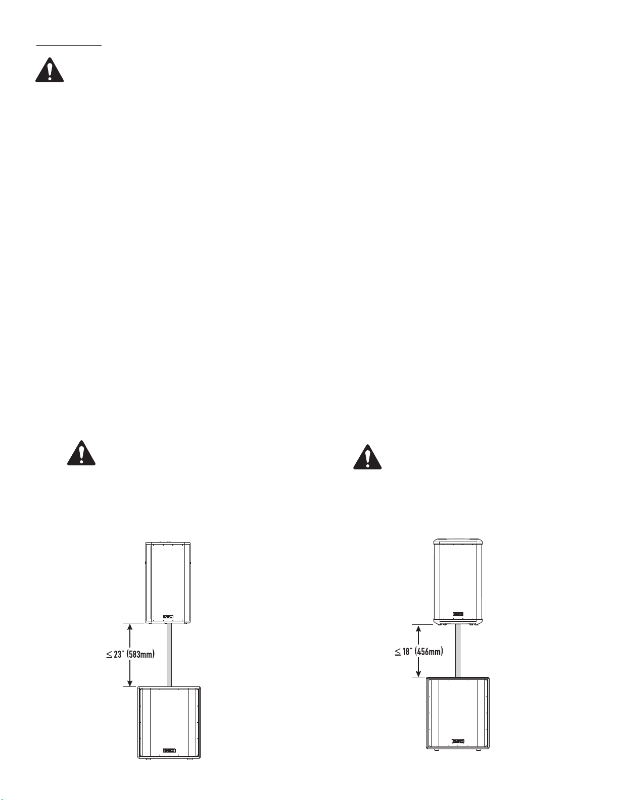
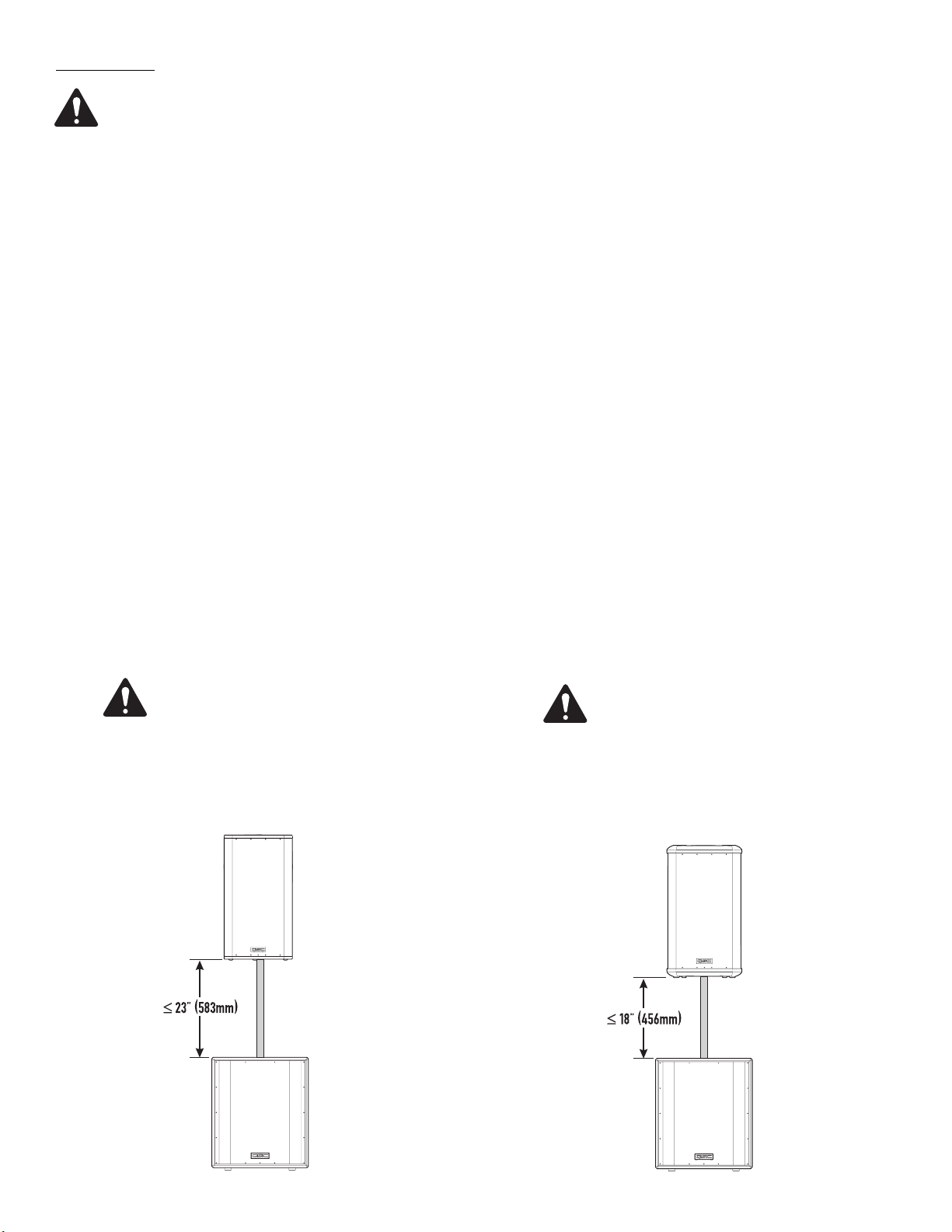
18- HPR152i WARNING! Do not use a loudspeaker support pole longer than 26” (660mm) when supported by QSC’s HPR151i or HPR181i subwoofer.
19- HPR122i WARNING! Do not use a loudspeaker support pole longer than 31” (787mm) when supported by QSC’s HPR151i or HPR181i subwoofer.
20- Do not use the HPR152i, HPR153i, HPR151i, or HPR181i oriented horizontally. Horizontal orientation can cause overheating and thermal limiting. The cooling
fins on the amplifier module must be vertically oriented in order to efficiently dissipate the heat generated by the amplifier.
21- The appliance shall not be exposed to dripping or splashing and no objects filled with liquids, such as vases, shall be placed on the apparatus.
2
Introduction
Congratulations and thank you for your purchase of this professional, powered loudspeaker product. To get the most from your investment, we
recommend you review all the information provided in this User Manual.
The HPR self-powered loudspeakers provide excellent sound quality, durable construction and clean, efficient, on-board amplification. Amplifiers are matched to the drivers with active equalization and precise crossover control. Active power limiting and thermal management extends
the life of drivers and the amplifier. The HPR series solves many application challenges with its great sound, built-in protection systems and selfcontained portability. HPR is the perfect solution for public performances, corporate events and private parties demanding flexible and excellent
sounding system solutions.
All models are self-powered using efficient amplifiers. AC line connection is fast and easy; an IEC-style quick-disconnect ensures reliable AC
mains connection while providing an easy-to-remove power cord for cabinet mobility. Audio enters the self-powered loudspeaker via a female
XLR connector with an additional parallel-wired male XLR output for daisy-chaining. No outboard signal processing is required as all models feature on-board filtering. The two-way and three-way full-range loudspeakers feature a switchable 100 Hz low-cut filter for use when subwoofers
are part of the system. Subwoofer models have two full-range input connectors (left and right) and two sets of output connectors; one pair featuring a 100 Hz low-cut filter and one pair passing full-range signal.
Rear-panel LEDs alert the user to AC power status, input signal presence, and limiter operation. Additionally, a blue front-panel "power on" LED
provides valuable visual power confirmation. It can also be disabled for applications where light toward the audience
may interfere with stage aesthetics. All models feature a 21-step detent Gain control allowing precise control and repeatable setup. The enclosures are made of high-quality plywood and are texture-coated in black. The models HPR122i, HPR152i and HPR153i have integral M10 suspension points for permanent installation and "flying" applications. Features vary by model, so please refer to sales brochures or the specifications
section of this manual for specific model information.
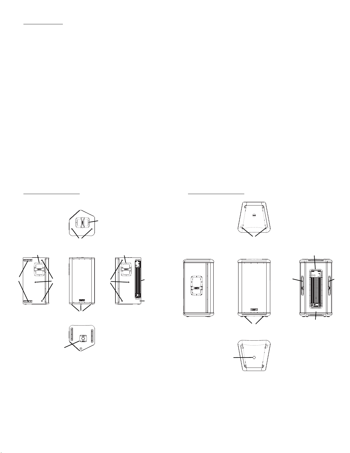
HPR122i Features HPR152i Features
2
6
22
5
66
1
3
5
4
6
6
4
2
3
5
1
6
2
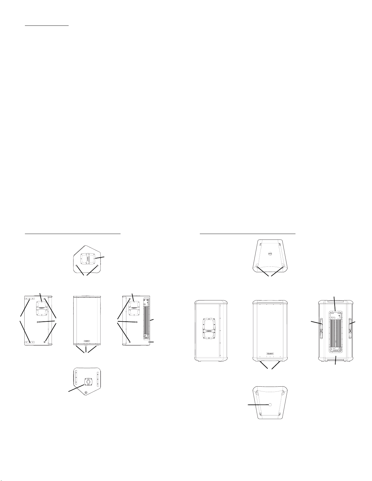
1- Pole Cup 4- Power Amplifier
2- Handles 5- Slip-resistant Feet
3- Grill 6- Rigging points
3
HPR153i Features
5
2
3
4
1
2
5
1- Power Amplifier 4- Slip-resistant Feet
2- Handles 5- Rigging Points
3- Grill
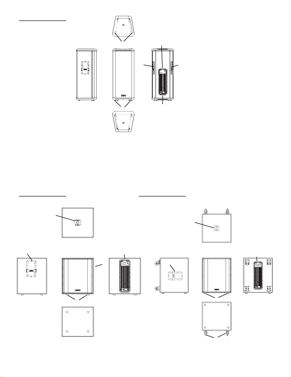
HPR151i Features HPR181i Features
1
2
2
3
5
4
2
1
4
3
5
6
1- Pole Cup 4- Power Amplifier
2- Handles 5- Slip-resistant Feet
4
3- Grill 6- Casters (HPR181W only)
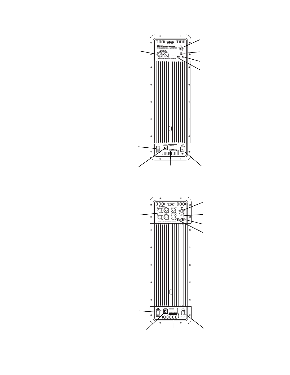
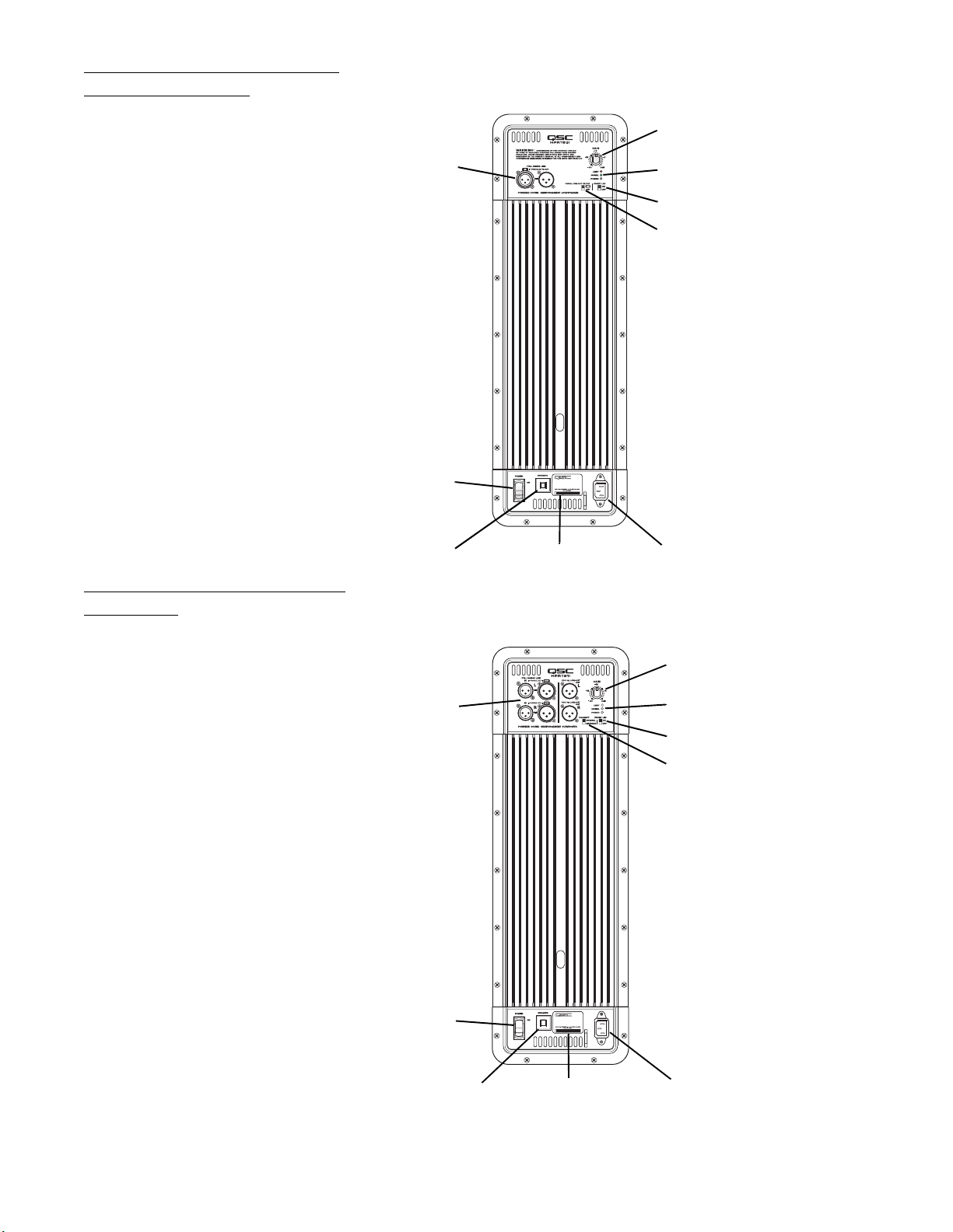
Full Range Amplifier Detail
2
1- Input and Output Connector(s)
2- Gain Control
3- Power, Signal, and Clip LED Indicators
4- Front LED Switch
5- 100 Hz Low-Cut Filter Switch
6- Power Switch
7- Circuit Breaker
8- Serial Number Plate
9- Latching IEC Power Inlet
Subwoofer Amplifier Detail
1
6
7
8
3
4
5
9
1- Input and Output Connector(s)
2- Gain Control
3- Power, Signal, and Clip LED Indicators
4- Front LED Switch
5- Polarity Switch
6- Power Switch
7- Circuit Breaker
8- Serial Number Plate
9- Latching IEC Power Inlet
2
1
6
7
8
3
4
5
9
5
Installation
Before placing, installing, rigging, or suspending any speaker product, inspect all hardware, suspension, cabinets, transducers, brackets
and associated equipment for damage. Any missing, corroded, deformed, or non-load rated component could significantly reduce the
strength of the installation or placement. Any such condition severely reduces the safety of the installation and should be immediately
corrected. Use only hardware which is rated for the loading conditions of the installation and any possible short-term, unexpected overloading. Never exceed the rating of the hardware or equipment.
Consult a licensed, Professional Engineer regarding physical equipment installation. Ensure that all local, state and national regulations
regarding the safety and operation of loudspeakers and related equipment are understood and adhered to.
How They Should Be Used
HPR122i: The HPR122i was designed to sit on the floor, stage, subwoofer enclosure, be suspended, or be pole mounted on a 35mm diameter
loudspeaker support pole. The pole can be part of a stand-alone loudspeaker stand or be inserted into the pole cup of the HPR151i or
HPR181i. Pole length must be no longer than 31” (787mm) when supported by the HPR151i or HPR181i subwoofer.
HPR152i: The HPR152i was designed to sit on the floor, stage, subwoofer enclosure, be suspended, or be pole mounted on a 35mm diameter
loudspeaker support pole. The pole can be part of a stand-alone loudspeaker stand or be inserted into the pole cup of the HPR151i or
HPR181i. Pole length must be no longer than 26” (660mm) when supported by the HPR151i or HPR181i subwoofer.
HPR153i: The HPR153i was designed to be suspended, or sit on the floor, stage, or on top of the subwoofer enclosure. Do not attempt to pole
mount this loudspeaker! There is no pole cup provided.
HPR151i: The HPR151i was designed to sit on the floor or on the stage. A pole cup on the top of the enclosure accepts 35mm loudspeaker
mounting poles. Rubber feet on the enclosure’s bottom help to minimize enclosure movement during operation. Do not pole mount or stack
more than one enclosure on top of the HPR151i enclosure.
HPR181i: The HPR181i was designed to sit on the floor or on the stage. A pole cup on the top of the enclosure accepts 35mm loudspeaker
mounting poles. Rubber feet on the enclosure’s bottom help to minimize enclosure movement during operation. Do not pole mount or stack
more than one enclosure on top of the HPR181i enclosure. As the casters will wear during normal use, it may be required to insert small foam
pieces between the wheels and frames to minimize rattling at high output levels.
HPR122i WARNING!
Do not use a loudspeaker support
pole longer than 31” (787mm)
when supported by the HPR151i or
HPR181i subwoofer. Note- each
pole cup is approximately 4”
(102mm) deep.
HPR152i WARNING!
Do not use a loudspeaker support
pole longer than 26” (660mm)
when supported by the HPR151i or
HPR181i subwoofer. Note- each
pole cup is approximately 4”
(102mm) deep.
6
Installation (continued)
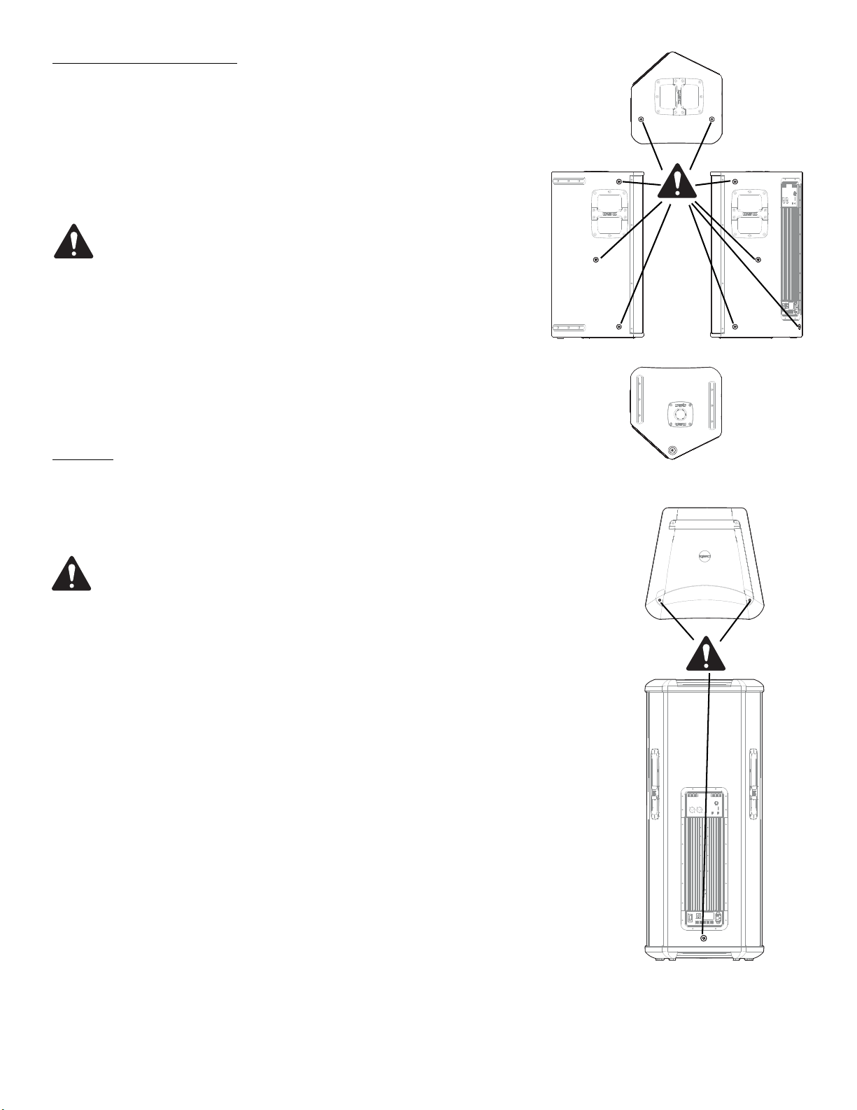
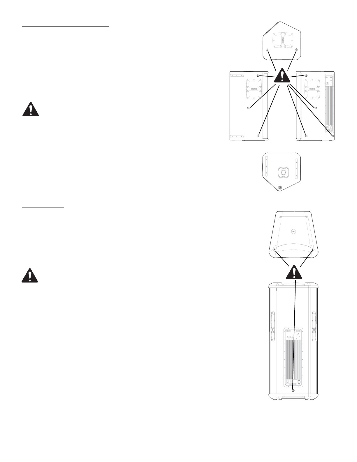
Pick Points (suspended installations)
The HPR152i and HPR153i enclosures feature three load-rated pick points.
The HPR122i enclosure features nine load-rated pick points. As shipped
from the factory, each pick point has a bolt or plug installed to retain the
air-tight design of the enclosure. Never operate the loudspeaker with the
pick points open (unsealed) as it will degrade the performance of the
product.
Ensure all pick-point fasteners are installed and correctly
tightened in order to maintain enclosure’s rated strength.
Additionally, air leaks resulting from missing hardware will
degrade the loudspeaker’s performance.
Use only QSC’s M10 forged shoulder eye bolts. Contact QSC
Technical Services department for complete information.
Cooling
This is a self-powered loudspeaker containing an internal power amplifier
that produces heat. Allow a minimum of 6” (152mm) clearance at cabinet
back for convection cooling. Keep anything that might restrict airflow
away from the rear of the enclosure (i.e draperies, fabric, etc...).
Pickpoints on the
HPR122i
Pickpoints on the
HPR152i and
HPR153i
Do not use the HPR152i, HPR153i, HPR151i, or HPR181i oriented
horizontally. Horizontal orientation can cause overheating and
thermal limiting. The cooling fins on the amplifier module must be
vertically oriented in order to efficiently dissipate the heat generated by the amplifier.
Do not install enclosures with their rear panels exposed to direct
sunlight. Direct sunlight will heat the amplifier module and reduce
its ability to produce full output. Install sunshades if the application merits.
Maximum ambient temperature for full performance to specification is 40° C. (104° F.).
Do not install enclosures where exposed to rain or other water
sources. The enclosure is not weatherproof. Outdoor installations
must provide protection from the elements.
7
AC Mains
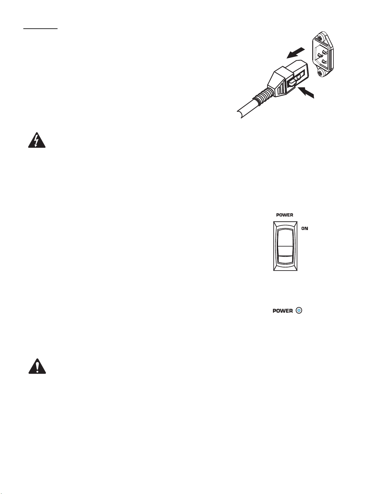
Connect AC power to the IEC socket on the back of the amplifier by locating
the IEC connector-end of the AC power cord and inserting it fully into the IEC
inlet on the power amplifier module. NOTE: Turn off the AC power switch
before connecting AC power.
The V-LOCK power cord has a special latching feature to prevent the power
cord from being unintentionally removed. The IEC plug and socket are both
blue in color so the power cord can be identified as an HPRi loudspeaker cord.
If the QSC-supplied cord becomes lost or damaged, a replacement 18 gauge
IEC power cord may be used. However, the latching system will only function
with a V-LOCK power cord available from QSC Audio Products.
The correct AC line voltage is shown on the serial number label, on
the rear panel. Connecting to the wrong line voltage may damage the
amplifier or increase the risk of electric shock.
AC Mains Disconnection
Turn the AC power switch to the off position. To remove the AC mains cord,
grasp the IEC connector’s plastic body, press the yellow latch release button
and pull, removing the connector from the socket.
Power Switch
Push in on the top of the rocker switch to apply AC mains power to the powered loudspeaker. Push in on the bottom of the rocker switch to turn the powered loudspeaker off.
When turned on, the blue POWER indicator LED and the red LIMIT (limiter)
indicator LED will illuminate; after a few seconds the red LIMIT indicator will
extinguish.
LED POWER Indicator
The blue LED POWER indicator will illuminate when the AC Power switch is
in the “ON” position, the AC mains power cord is connected properly, and the
AC mains are functioning properly. The LED POWER indicator will extinguish
when the AC Power switch is in the “off” position or AC mains power has
been removed from the loudspeaker.
To remove AC cord, press the yellow latch
release button and pull on the connector body.
AC power switch
Power “on” indicator LED
If the POWER indicator does not illuminate when the Power switch is placed
in the “on” position, verify the AC mains line cord is properly attached to the
loudspeaker and plugged into the AC outlet. Verify the outlet is functioning
properly.
If the AC mains cordset is serviceable and the AC mains outlet is operating properly, but the loudspeaker fails to operate, the loudspeaker
may require servicing. Contact QSC’s Technical Services department.
System Power Sequencing
Proper power turn on sequence can help to prevent unexpected sounds from
your system (pops, clicks, thumps). These unintended sounds can damage
drivers and cause audience members to question the professionalism of the
sound team. Turn on and off the system in the proper order to avoid unexpected sounds.
Power On Sequence: Turn on all source devices (CD players, mixers), turn
on subwoofer, then turn on the “top-boxes” (HPR122i, HPR152i and HPR153i).
8
Input Connections
Full-range models have one female XLR line-level input marked
FULL RANGE LINE IN.
Subwoofers have a second set of connectors, one for the left
channel’s audio and one for the right channel’s audio.
We recommend balanced connections be used. Balanced connections will reduce AC hum and interference, especially with
long cable runs. Unbalanced connections may be suitable for
short cables. The input impedance is 22k ohm for balanced connections or 11k ohm for unbalanced connections. The signal's
source impedance should be less than 600 ohms.
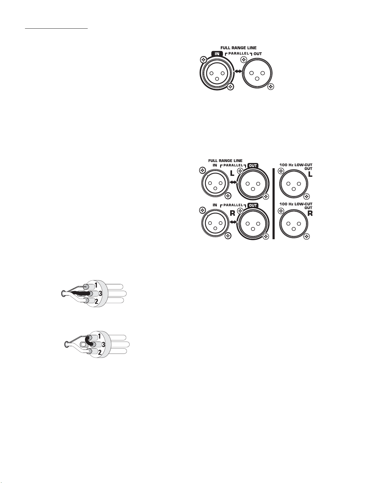
Full-range loudspeaker’s Input
(IN) and Output (OUT) Connectors
HPR122i, HPR152i and HPR153i: Insert the male XLR input
into the jack marked FULL RANGE LINE IN. Ensure the connector
is fully seated.
HPR151i and HPR181i: Insert the left channel’s XLR input into
the left channel’s (L) FULL RANGE LINE IN connector. Insert
the right channel’s XLR connector into the right channel’s (R)
FULL RANGE LINE IN connector. If a single input signal is
used, plug into either the L (left) or R (right) channel’s input.
If two input signals are used, plug the left channel’s signal
into the connector marked FULL RANGE LINE IN L (the top
input connector) and the right channel’s signal into the connector marked FULL RANGE LINE IN R (the bottom input connector). When two input signals are applied, the subwoofer’s
gain is automatically increased 6dB as the subwoofer will
likely be used with two full-range loudspeakers.
Balanced inputs: Connect to the plug as shown.
1= shield (ground)
3= minus (-)
2= plus (+)
Unbalanced inputs: Connect to the plug as shown. Pin 3 and
pin 1 must be connected with a jumper as shown.
Subwoofer loudspeaker’s Input (IN)
and Output (OUT) Connectors
1= shield (ground)
3= jumper to pin 1
2= plus (+)
9
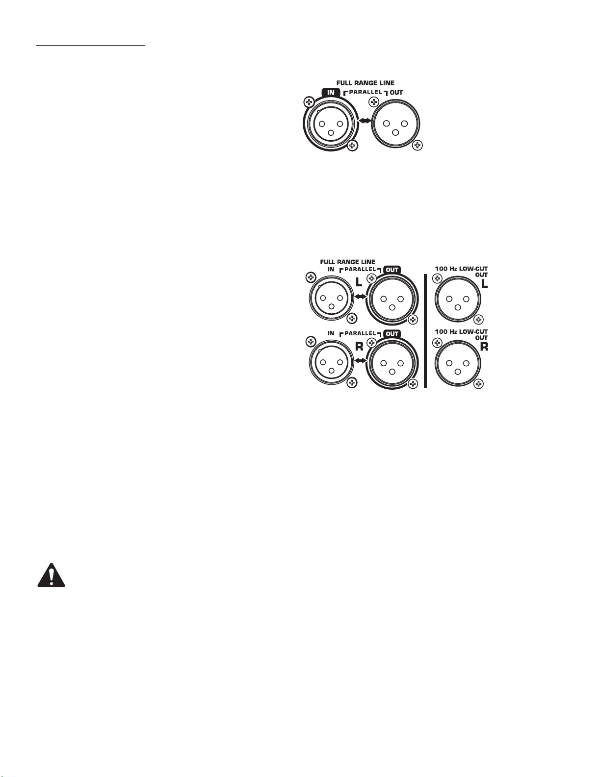
Output Connections
Full-range models have one XLR output connector marked
FULL RANGE LINE OUT. The output connector is wired in
parallel with the input enabling connection of multiple
enclosures in a “daisy-chain” fashion.
Subwoofer models have two sets of output connectors,
one set for the left and one set for the right audio channel. Each channel has a FULL RANGE LINE OUT connector
and a 100 Hz LOW-CUT OUT connector (active 100 Hertz
filter applied, non-defeatable).
We recommend balanced connections be used. Balanced
connections will reduce AC hum and interference, especially with long cable runs. Unbalanced connections may
be suitable for short cables.
HPR122i, HPR152i and HPR153i
Insert the XLR connector into the jack marked FULL
RANGE LINE OUT. Connect the other end of the cable to
the next down-stream audio device’s input connector. The
output connector is wired in parallel with the input connector and is not effected by the 100 Hertz low-cut filter
switch setting.
Full-range loudspeaker’s Input (IN)
and Output (OUT) Connectors
Subwoofer loudspeaker’s Input (IN)
and Output (OUT) Connectors
HPR151i and HPR181i
FULL RANGE LINE OUT: Use the outputs marked FULL
RANGE LINE OUT (Left and/or Right) when connecting to
down-stream powered loudspeakers which accept fullrange audio or have their own filtering.
100 Hz LOW-CUT: Use the outputs marked 100 Hz LOWCUT OUT (L and/or R) when connecting to downstream
powered loudspeakers that have no low-frequency filtering but the low-frequency roll-off is desired. Do not use
the 100 Hz LOW-CUT OUT connectors for connecting to
other subwoofers. Instead, use the FULL RANGE LINE
OUT. Be sure to turn off any loudspeaker connected to the
100 Hz LOW-CUT OUT before turning off the subwoofer’s
AC power. This prevents any undesired turn-off transients
(thumps, bumps) in the connected devices.
If using the subwoofer’s 100 Hz LOW-CUT OUT
connector to provide signal to the top-boxes
(HPR152i and HPR153i), be sure the top-box’s lowcut filters are OFF. Do not apply a second filter as
the sonic performance of the system will be notably degraded.
IMPORTANT! If using full range loudspeakers
from another manufacturer, we recommend they
be connected to the QSC subwoofer’s 100 Hz LOWCUT OUT. This will ensure proper phasing of the
full range loudspeaker with respect to the subwoofer.
10
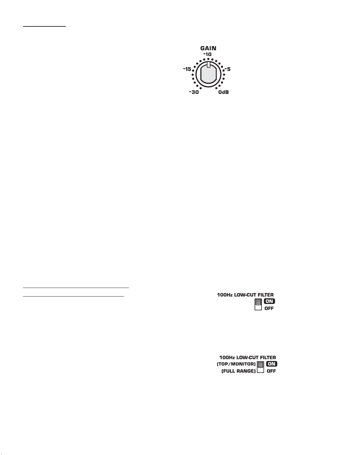
GAIN Control
The GAIN control is marked in dB of attenuation. There are
21 detents for repeatable adjustments. Turn the GAIN control clockwise to increase gain and counter clockwise to
decrease gain.
The upper 14 steps are about 1 dB each and settings
should normally be made within this range. When operating with the GAIN set below -15 dB, it may be possible to
exceed input headroom. If this is the case, reduce the input
signal strength and increase the gain of the loudspeaker
amplifier.
Subwoofer Gain Notes
Scenario: One input signal only to the subwoofer,
one full-range loudspeaker for each subwoofer- The
HPR loudspeakers are designed to be used as a system,
typically using one subwoofer for each full-range loudspeaker. If the subwoofer and the full-range loudspeaker
have their Gain controls set identically, the tonal balance
will be correct (or very close to correct).
Scenario: Two input (L+R) signals to the subwoofer,
and two full-range loudspeakers per subwoofer-
When two inputs (L+R) are applied to the subwoofer, an
additional gain of 6dB is automatically applied to the subwoofer. The additional gain is added to the subwoofer to
keep the tonal balance correct for use with two full-range
loudspeakers.
Gain control.
100 Hertz Low-Cut Filter Switch:
HPR122i, HPR152i, and HPR153i
Below the LED indicators is a small recessed slide-switch
that enables or disables a 100 Hertz low-cut filter.
Filter OFF (Full Range)
Turn the filter OFF when using without subwoofers or dedicated low-frequency enclosures.
Filter ON (100 Hz Low-Cut)
Turn the filter ON when using with optional subwoofers or
low-frequency systems. This results in proper subwoofer
operation and allows the top box to provide improved clarity in the middle and high frequencies. HPR122i: If using
as a floor monitor, turn the filter ON for improved vocal
range clarity and to reduce low frequency build-up on
stage.
HPR152i and HPR153i 100 Hertz low-cut filter switch.
HPR122i 100 Hertz low-cut filter switch.
11

Front LED Switch
The Front LED Switch, located on the rear panel, is used to enable or disable
the LED located on the front of the enclosure near the bottom of the grill. Slide
the switch to the ON position to enable the front LED and slide it to the OFF
position to disable the front LED.
Most applications merit the use of the Front LED so power status can be visually confirmed, easily and quickly. For applications where the LED may distract
audience members, it is easily disabled by sliding the FRONT LED switch to
the OFF position.
Polarity Switch (HPR151i and HPR181i)
When all loudspeakers in system are properly polarized, a positive polarity
drive signal results in a forward excursion of all loudspeaker cones. This, in
turn, sets up a positive reinforcement of the sound wavefront (each loudspeaker reinforces the actions of the other loudspeakers). This effect is most
pronounced at low (bass) frequencies.
If a loudspeaker is not properly polarized, its cone moves inward while the
properly polarized loudspeaker’s cones move outward. The inward movement
will effectively cancel the bass response of a similarly-sized driver in the system, resulting in a reduction in the bass content.
It is critically important to maintain correct phasing in a loudspeaker system in
order to realize maximum performance. Polarity can be altered by miswired
input cables, interconnecting cables, mixer polarity switches set incorrectly,
just to name a few likely culprits.
Front LED switch.
Polarity switch.
To make matters a bit more complicated, phasing is also influenced by the
position of loudspeakers with respect to one another and by their position in a
given room. It is possible to have all loudspeakers polarized properly (electrically) and yet achieve better bass response by having the subwoofer reverse
polarized. It is even possible to achieve improved bass response from the system with multiple subwoofers polarized differently. Be aware that perceived
bass response also will change with the listener’s position, so move around
the room (venue) when testing your setup.
Because phasing problems can so drastically effect the bass output of a system, the subwoofers are equipped with a switch marked POLARITY. When set
to NORMAL, the polarity is such that a positive going input will cause the cone
to move outward. When set to REVERSE, the input signal has its polarity
reversed and a positive going input will cause the loudspeaker’s cone to move
inward.
How to Use the Polarity Switch
When using QSC subwoofers and QSC full range loudspeakers, NORMAL
polarity will result in the best bass response IF the full range loudspeakers are
sitting on or very close to the subwoofers. If the subwoofers are some distance away from the full range loudspeakers, polarity change may be of benefit.
Start with all subwoofer POLARITY switches in the NORMAL position. This
applies to systems with one subwoofer as well. Then, with your system at or
near expected operating levels, change the polarity of each subwoofer INDIVIDUALLY. Then walk around the venue and assess the overall bass response.
Select the polarity that results in the best overall system bass response.
IMPORTANT! If using full
range loudspeakers from
another manufacturer,
we recommend they be
connected to the QSC
subwoofer’s 100 Hz LOWCUT OUT. This will
ensure proper polarity of
the full range loudspeaker with respect to
the subwoofer.
12

SIGNAL Indicator LED
The green SIGNAL indicator alerts the user to the presence of an input signal to the
HPR loudspeaker.
Normal Indication
The green SIGNAL indicator illuminates when the input signal exceeds -25 dB.
If No Indication
Check Gain settings and increase gain if necessary. Check input connections and
audio source for signal. If the red LIMIT LED illuminates, refer to the LIMIT indicator
section, below.
Abnormal Indication
If the green SIGNAL LED illuminates with no signal input, there may be system oscillations or some other malfunction. Disconnect the input or fully reduce the gain. If
the green SIGNAL LED remains on, the amp may need servicing.
LIMIT Indicator LED
The red LIMIT indicator alerts the user to several conditions within the HPR loudspeaker:
Continuous Bright Red Light
• Indicates protective mute mode.
• The speaker normally passes through muting for several seconds after applying
power, after which the light should go out, and sound should be heard.
• If the speaker enters Mute during operation, it has either overheated or developed a
fault.
• Overheating should correct itself within 1-2 minutes, after which sound should
resume. See below for a full explanation of thermal protection.
• Short periods of muting indicate a component fault. In this case AC power should be
removed and the speaker serviced.
LED indicators.
Momentary Bright Red Flashes
• During operation, bright flashing indicates clipping (overdrive distortion). This is normally due to excessive volume and may be accompanied by audible distortion.
• If the loudspeaker mutes repeatedly during output peaks, there may be a component
fault; AC power should be removed and the loudspeaker serviced.
Continuous Half-bright Light
• Indicates that the internal limiter is reducing gain, due to prolonged clipping and/or
excessive temperature.
• After several seconds of severe clipping, the limiter will reduce power to protect the
speaker and improve the sound. This results in a steady, half-bright red indication.
Any further clipping will still result in bright flashes on top of the steady half-bright
indication. When the program level is reduced, the limiter will clear after several seconds, and the red indicator will go out.
• If the power module overheats, the first response is to trigger limiting, to reduce volume and limit further temperature rise. This results in a steady half-bright illumination that does not clear even after reducing program level. It may take several
minutes for temperature to drop and clear the limiter. During this time, the exposed
heat sink will feel uncomfortably hot to the touch. If overheating continues, the
amplifier will ultimately mute, resulting in a full-bright red indication. When muting
clears, the amplifier will resume operation, with thermal limiting still active until it
further cools off.
• Overheating is usually caused by excessive ambient temperature, since the internal
temperature rise of the power module is relatively low. Protect the speaker from
excessive temperatures, such as being placed over a heater vent, or allowing direct
sunlight to impinge upon the heat sink surface.
13
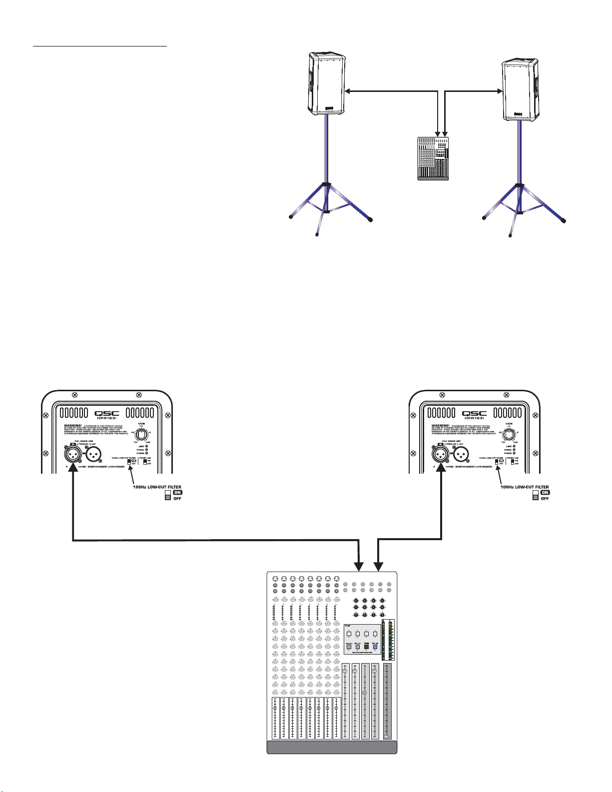
Application Example #1
This example shows a two-channel (stereo) setup utilizing two
top-boxes.
Application Example #1 physical diagram.
Audio signals for the Left and Right channels are supplied by
the mixer console. This signal source can be just about any
variable-output level audio source, such as DJ mixers, professional CD players, or computer-based audio signal sources.
Audio output from the mixer’s Left channel is connected to the
Left top-box’s FULL RANGE LINE IN connector. Audio output
from the mixer’s Right channel is connected to the Right topbox’s FULL RANGE LINE IN connector. Turn off each top-box’s
100 Hz LOW-CUT FILTER. This will provide more low-frequency
content (bass) in the absence of a subwoofer.
HPR122i, HPR152i, or HPR153i
Channel 1 or Left Channel
HPR122i, HPR152i, or HPR153i
Channel 2 or
Right Channel
14
Mixer or Other Audio Source
Application Example #1 hookup diagram.
Use only high-quality balanced cables for
interconnecting the audio equipment.
Ensure the top-boxes have their 100 Hz LOWCUT FILTER switched OFF when using without
a subwoofer or other dedicated low-frequency enclosure.
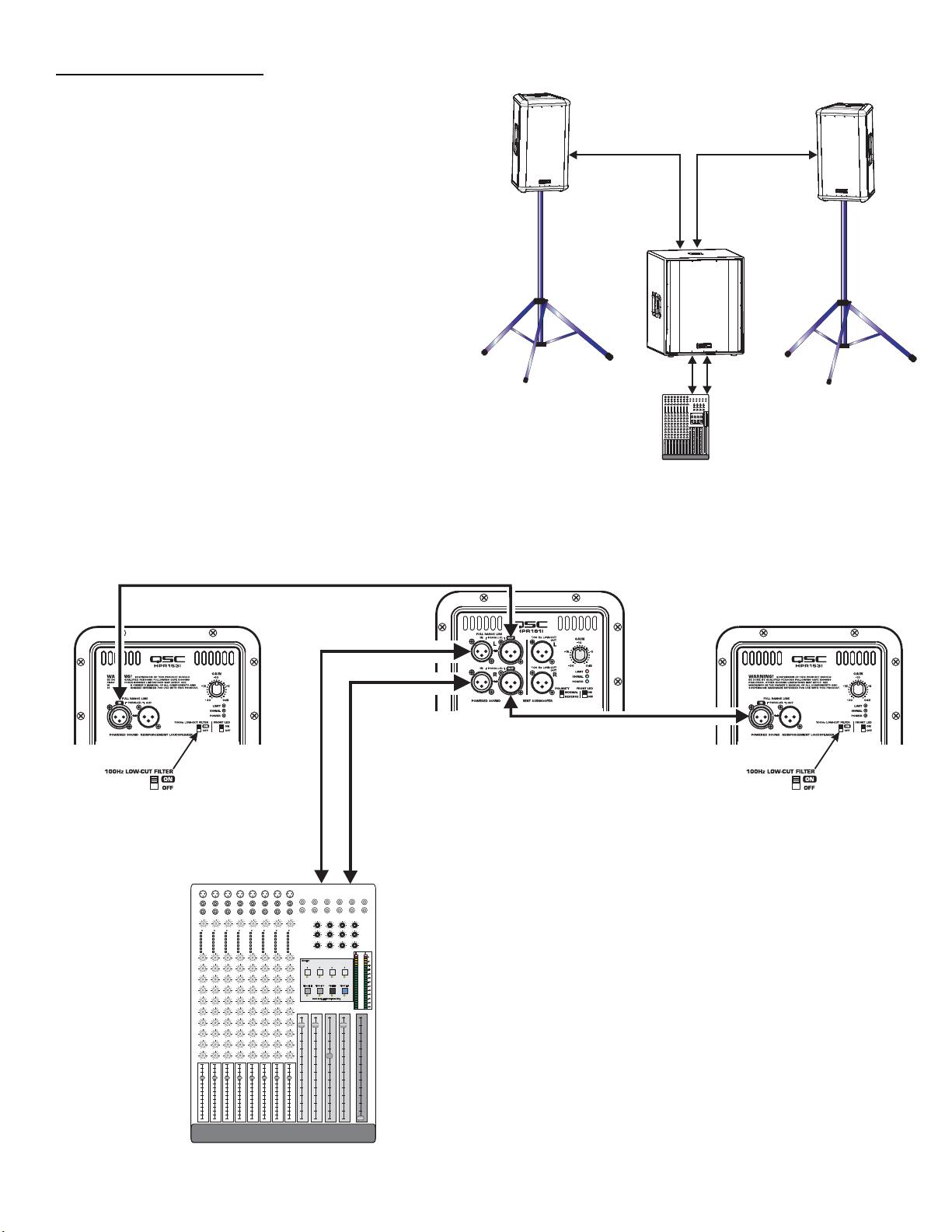
Application Example #2
This example shows a two-channel (stereo) setup utilizing one
subwoofer and two top-boxes.
Application Example #2 physical diagram.
Audio signals for the Left and Right channels are supplied by
the mixer console. This signal source can be just about any
variable-output level audio source, such as DJ mixers, professional CD players, or computer-based audio signal sources.
Audio output from the mixer is connected to the subwoofer’s
Left (L) and Right (R) channels. The subwoofer’s R and L FULL
RANGE LINE OUT connectors are used to connect to its respective top-box. Turn ON each top-box’s 100 Hz LOW-CUT FILTER.
Alternately, the top-boxes could be connected to the subwoofer’s 100 Hz LOW-CUT OUT and the top-boxes 100 Hz
LOW-CUT FILTERs turned off. The only possible issue with this
method of connection is unexpected noises (turn-off thumps) if
the subwoofer is powered up or down while the top boxes are
on. If connected as shown, power sequencing is not an issue.
HPR151i or HPR181i
Channel 1 or
Left Channel
Channel 2 or
Right Channel
HPR122i, HPR152i, or HPR153i
Mixer or Other Audio Source
Application Example #2 hookup diagram.
Use only high-quality balanced cables for interconnecting the audio equipment.
Ensure the top-boxes have their 100 Hz LOWCUT FILTER switched ON when connecting to
the subwoofer’s FULL RANGE LINE OUT as a signal source.
Also, be sure to keep Left and Right (marked L or
R) channels segregated properly so that soundstage imaging remains consistent.
HPR122i, HPR152i, or HPR153i
15
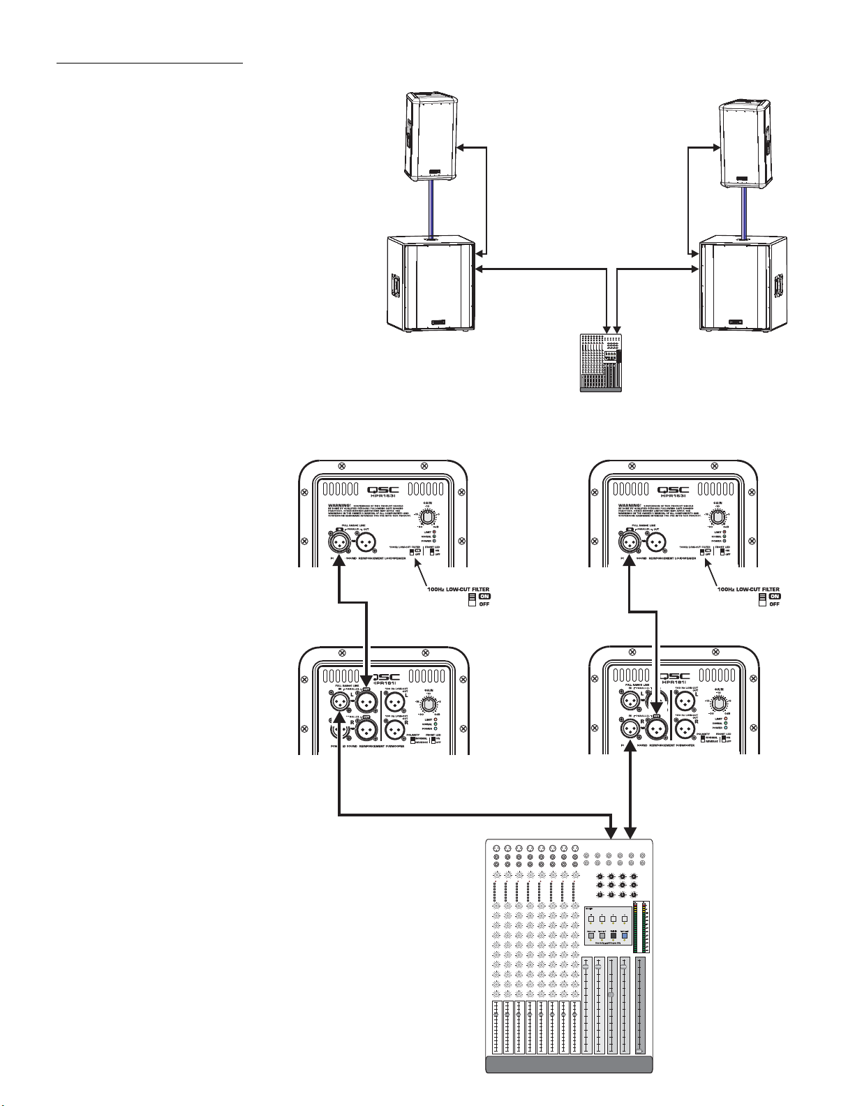
Application Example #3
This example shows a two-channel (stereo) setup utilizing two subwoofers and two top-boxes.
Audio signals for the Left and Right channels are supplied
by the mixer console. This signal source can be just about
any variable-output level audio source, such as DJ mixers, professional CD players, or computer-based audio
signal sources.
Audio output from the mixer is connected to the subwoofer input of each channel. Each subwoofer’s FULL
RANGE LINE OUT connector is used to connect to its
respective top-box. Turn ON the top-box’s 100 Hz LOWCUT FILTER.
Alternately, the top-boxes could be connected to the subwoofer’s 100 Hz LOW-CUT OUT and the top-box 100 Hz
LOW-CUT FILTER turned off. The only possible issue with
this method of connection is unexpected noises (turn-off
thumps) if the subwoofer is powered down before the
top-boxes. If connected as shown, power sequencing is
not an issue.
Application Example #3 physical diagram.
Channel 1 or Left Channel
Channel 2 or Right
Channel
Application Example #3 hookup diagram.
Use only high-quality balanced cables for
interconnecting the audio equipment.
Ensure the top-boxes have their 100 Hz LOWCUT FILTER switched ON when connecting
to the subwoofer’s FULL RANGE LINE OUT as
a signal source.
Also, be sure to use either the Left or Right
(marked L or R) on the subwoofers. If the
subwoofer’s input is connected to the Right
(R) channel connector and the output to the
top-boxes is connected to the Left (L) channel connector, no signal will reach the topbox (no sound from the top-box).
HPR122i, HPR152i, or HPR153i
HPR151i or HPR181i
Mixer or Other Audio Source
16
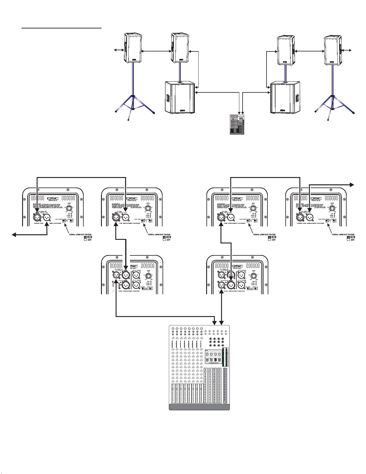
Application Example #4
This example shows a two-channel
(stereo) setup utilizing two subwoofers and multiple top-boxes.
This is the same as Application
Example #3 except an additional
top-box has been added to each
channel (and more could be added).
To connect to additional top-boxes,
connect a cable from the last top
box’s FULL RANGE LINE OUT connector to the next top-box’s FULL
RANGE LINE IN connector. Up to 20
top-boxes could be “daisy-chained”
without degrading signal quality.
Application Example #4 physical diagram.
Channel 1
or
Left Channel
Channel 2
or
Right Channel
HPR122i, HPR152i, or HPR153i
Application Example #4 hookup diagram.
Use only high-quality balanced cables for
interconnecting the audio equipment.
Ensure the top-boxes have their 100 Hz LOWCUT FILTER switched on when connecting to
the subwoofer’s FULL RANGE LINE OUT as a
signal source.
Also, be sure to use either the Left or Right
(marked L or R) on the subwoofers. If the subwoofer’s input is connected to the Right (R)
channel connector and the output to the topboxes is connected to the Left (L) channel
connector, no signal will reach the top-box
(no sound from the top-box).
HPR122i, HPR152i, or HPR153i
HPR151i or HPR181i
Mixer or Other Audio Source
17
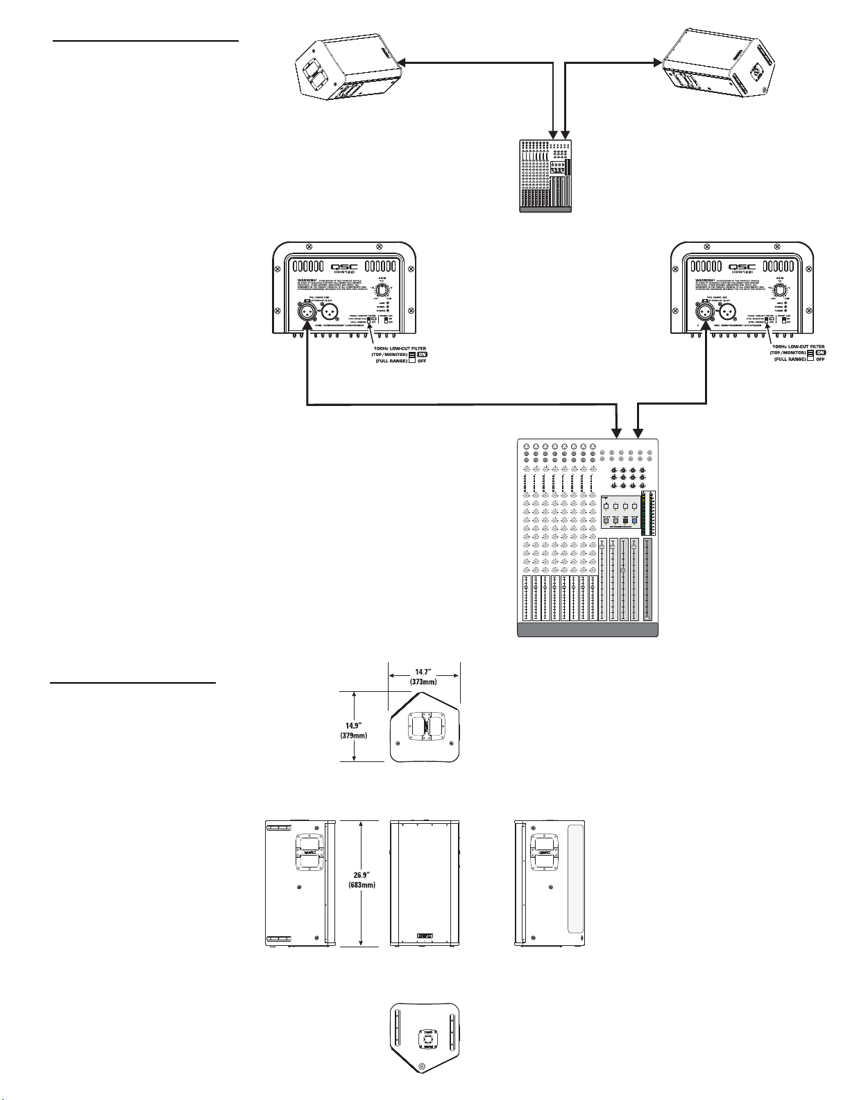
Application Example #5
This example shows a two-channel (stereo) setup utilizing two
HPR122i loudspeakers as floor
monitors.
Audio signals for the Left and
Right channels are supplied by the
mixer console auxiliary buss. This
allows the monitor level to be
adjusted independently from the
main (house) mix.
Audio output from the mixer’s Left
auxiliary buss is connected to the
Left top-box’s FULL RANGE LINE
IN connector. Audio output from
the mixer’s Right auxiliary buss is
connected to the Right floor monitor’s FULL RANGE LINE IN connector. Turn ON each monitor’s 100 Hz
LOW-CUT FILTER. This will
improve vocal clarity and minimize
low frequency (bass) buildup on
stage.
Application Example #5 physical diagram.
Channel 1
or
Left Channel
HPR122i
Application Example #5 hookup diagram.
Use only high-quality balanced cables for
interconnecting the audio equipment.
Ensure the floor-monitors have their 100 Hz
LOW-CUT FILTER switched ON to provide
improved clarity in the middle- and high- frequencies. This also reduces bass build-up on
stage.
Channel 2
or
Right Channel
Mixer or Other Audio Source
HPR122i
Dimensions, HPR122i
18
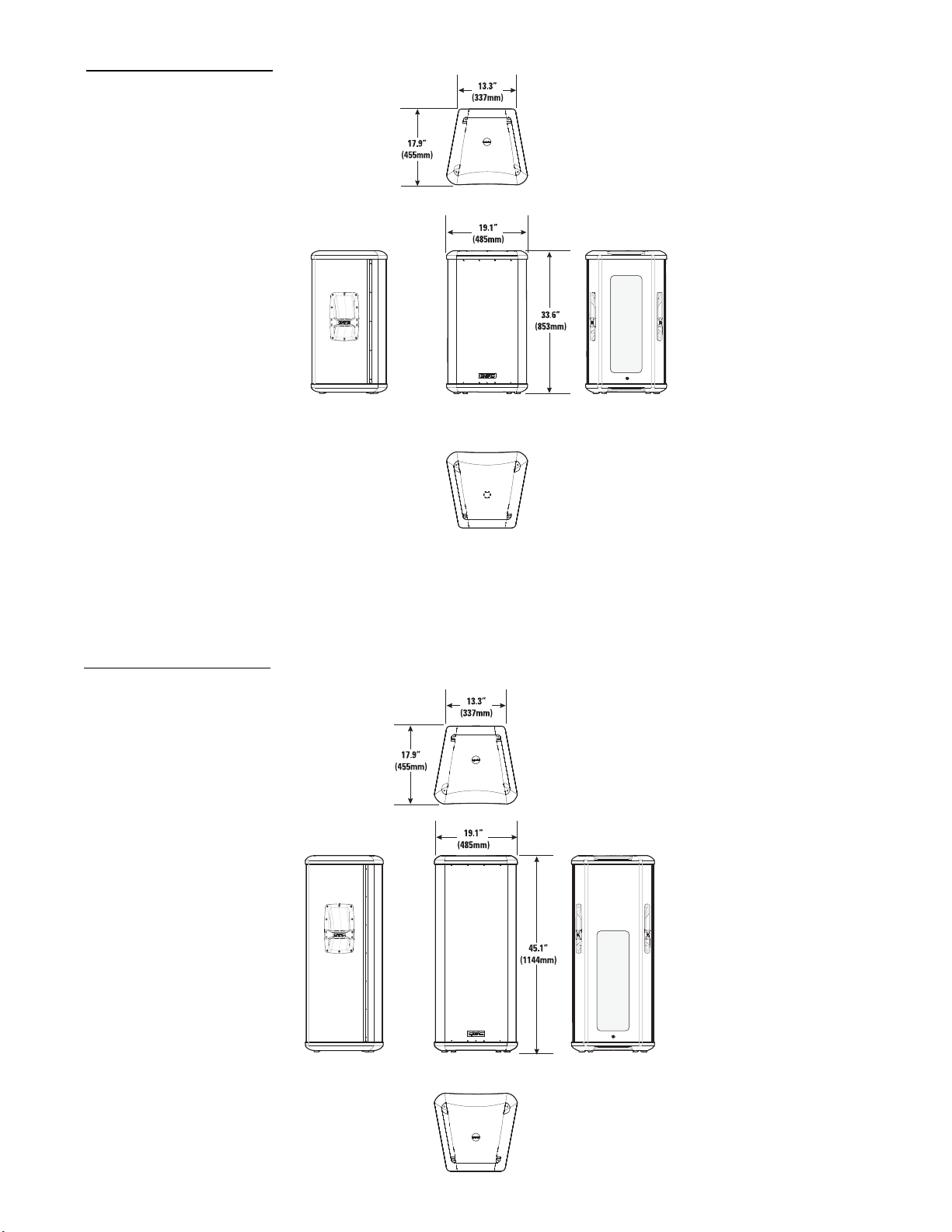
Dimensions, HPR152i
Dimensions, HPR153i
19
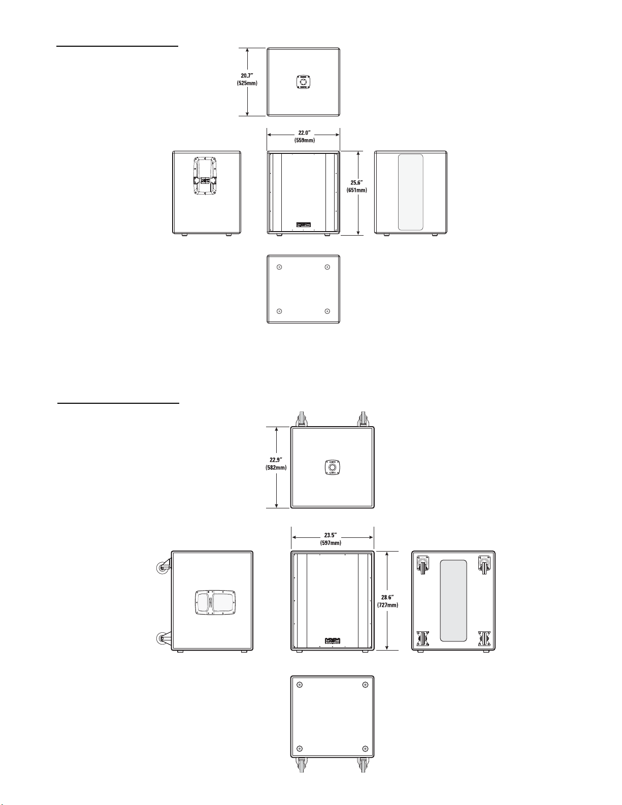
Dimensions, HPR151i
Dimensions, HPR181i
20
Specifications, HPR122i
HPR122i
Frequency Response, -3dB 62-18k Hz
Frequency Range, -10dB 53-22k Hz
Maximum Peak SPL 131dB
Nominal coverage, H x V 75°x75°
Directivity Index 9.7
Directivity Factor 9.4
Transducer Description 12” (309mm) transducer with 3” (76mm) voice coil
1” (25mm) throat compression drive
Acoustic Crossover Freq. 2,000 Hz
Amp Power 400 Watts, low frequency
100 Watts, high frequency
Input Sensitivity 0.775 V
Input Headroom/Clipping 10 V
rms
(+22.2dBu)
rms
(+0dBu)
Input Connector/Impedance XLR female, 22k Ohm, balanced, line-level input
(unbalanced, 11k Ohm)
Output Connector XLR male, wired in parallel with Input connector
Controls, Indicators, and Gain control, 100 Hz low-cut filter switch, Front LED on/off switch, Limit/Clip (red LED), Signal presence (green LED), AC Power (blue LED),
Adjustments AC Power switch, AC circuit breaker
Protection, Agency certs. Thermal limiting, On/Off muting, power limiting, DC protection, short circuit protection, ultrasonic protection, RF protection, UL/CE listed
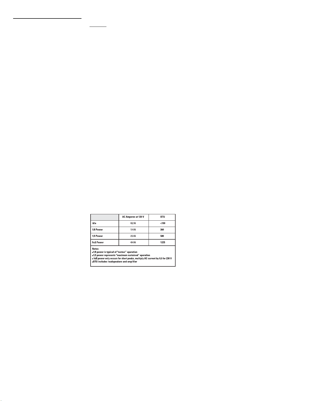
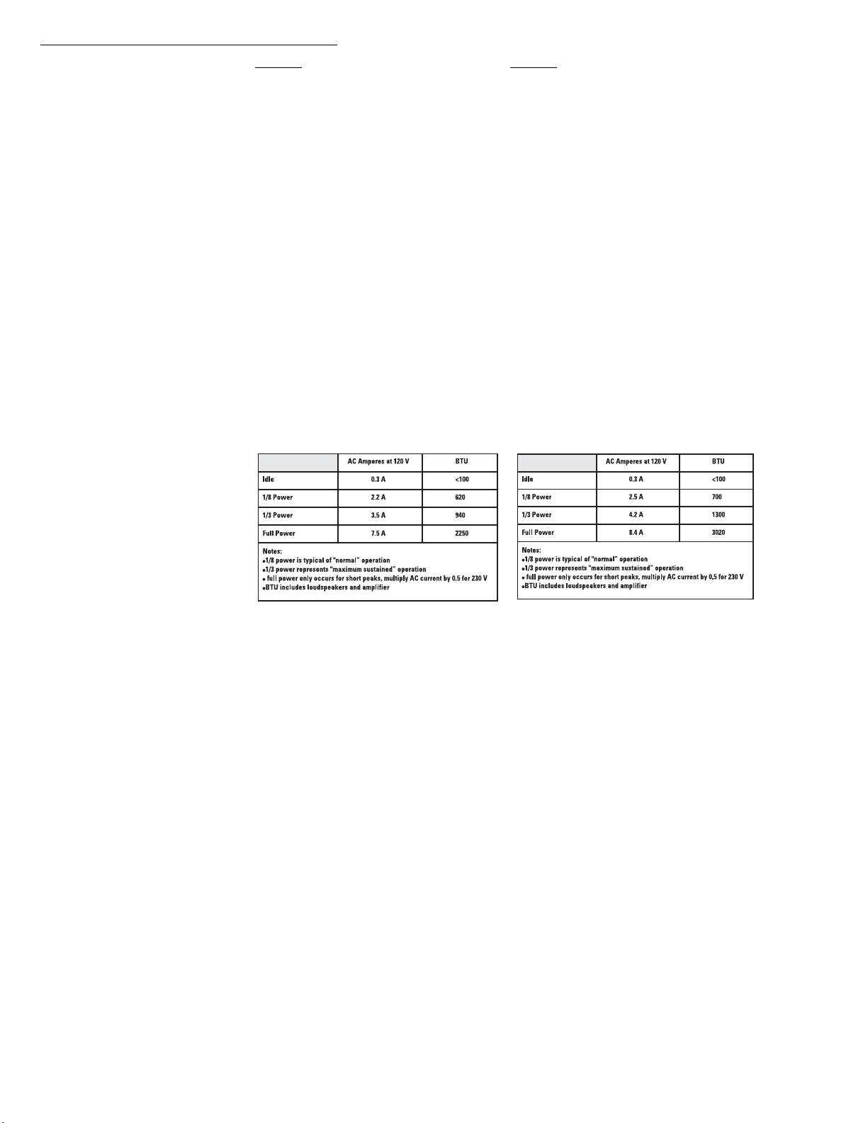
AC Power Requirements
AC Power Connector and Cordset Factory supplied IEC cordset: 9’ (3m) #18AWG 120V North American or European 230V cordset
Dimensions (height, width, depth) 26.9” (683mm) x 14.7” (373mm) x 14.9” (379mm)
Installation Clearance Allow for 6.0” (152mm) of free space behind the enclosure to assure proper amplifier cooling
Weight 60 lb/27.2 kg
Finish and Grill Wear-resistant textured paint finish on plywood enclosure and powder-coated perforated steel grill
Notes:
1- Maximum Peak SPL: Calculated by adding the loudspeaker’s sensitivity (1W at 1m) to the peak power (dBw) of the amplifier provided.
2- Directivity Index (DI): Difference between on-axis SPL and average SPL (considering all axes) for the specified coverage range. DI= 10 log Q
3- Directivity Factor (Q): Directivity index expressed as a power ratio Q=10 exp DI/10
4- Amplifier Power: The maximum sustained power at less than 1% clipping, averaged over the intended frequency range,
5- Input Sensitivity: The sine-wave input voltage required to reach amplifier clipping, measured within the frequency range used to determine Maximum Peak SPL, with the gain on “normal” and no gain reduction
due to limiting.
6- Input Headroom/Clipping: Maximum input voltage.
7- Input Connector/Impedance: RF shunt capacitance should not reduce impedance by more than 30% at 20k Hz.
21
Specifications, HPR152i and HPR153i
HPR152i HPR153i
Frequency Response, -3dB 54-17.5k Hz 41-17.5k Hz
Frequency Range, -10dB 47-20k Hz 36-20k Hz
Maximum Peak SPL 135dB 133dB
Nominal coverage, H x V 90°x60° 90°x40°
Directivity Index 9.4 11.1
Directivity Factor 8.7 12.9
Transducer Description 15” (381mm) transducer with 3” (76mm) voice coil 15” (381mm) transducer with 3” (76mm) voice coil
1” (25mm) throat compression driver 6.5” (165mm) transducer with 1” (25mm) voice coil
Acoustic Crossover Freq. 2,000 Hz 500 and 2,000 Hz
Amp Power 400 Watts, low frequency 400 Watts, low frequency
100 Watts, high frequency 100 Watts, mid frequency
1” (25mm) throat compression driver
100 Watts, high frequency
Input Sensitivity 0.775 V
Input Headroom/Clipping 10 V
rms
(+0dBu) 0.775 V
rms
(+22.2dBu) 10 V
rms
(+22.2dBu)
rms
(+0dBu)
Input Connector/Impedance XLR female, 22k Ohm, balanced, line-level input XLR female, 22k Ohm, balanced, line-level input
(unbalanced, 11k Ohm) (unbalanced, 11k Ohm)
Output Connector XLR male, wired in parallel with Input connector XLR male, wired in parallel with Input connector
Controls, Indicators, and Gain control, 100 Hz low-cut filter switch, Front LED on/off switch, Limit/Clip (red LED), Signal presence (green LED), AC Power (blue LED),
Adjustments AC Power switch, AC circuit breaker
Protection, Agency certs. Thermal limiting, On/Off muting, power limiting, DC protection, short circuit protection, ultrasonic protection, RF protection, UL/CE listed
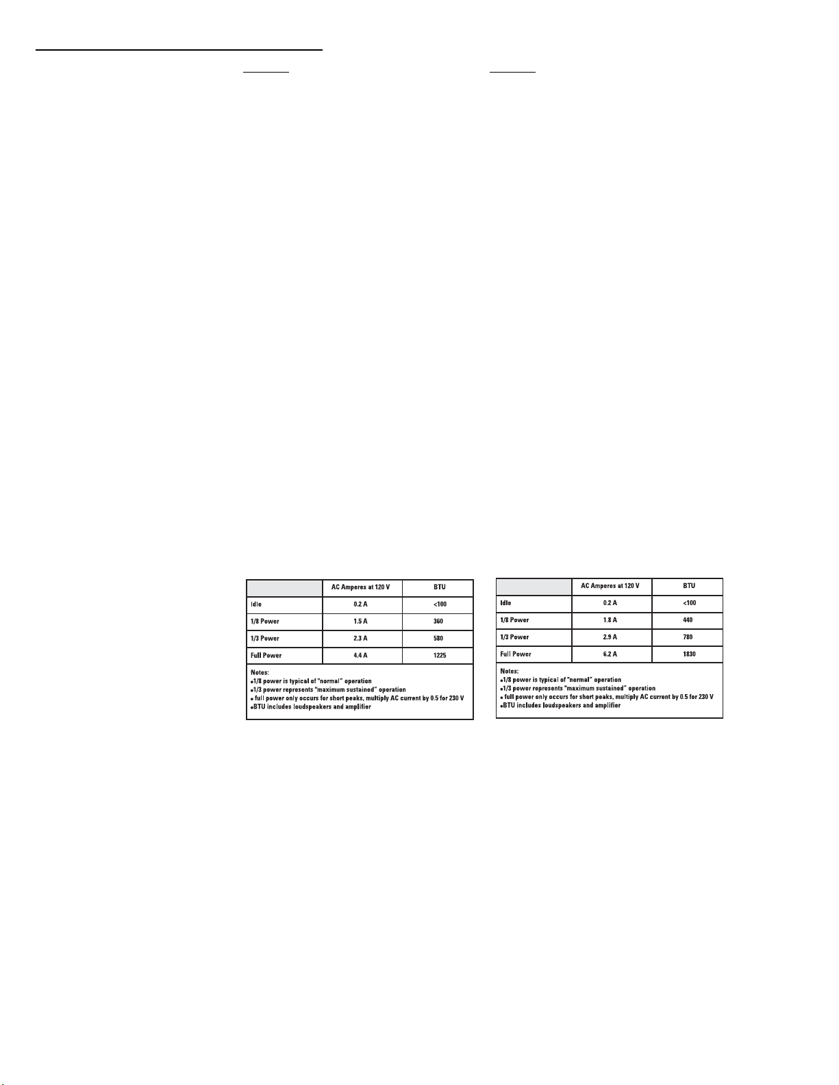
AC Power Requirements
AC Power Connector and Cordset Factory supplied IEC cordset: 9’ (3m) #18AWG 120V North American or European 230V cordset
Dimensions (height, width, depth) 33.6” (853mm) x 19.1” (485mm) x 17.9” (455mm) 45.1” (1144mm) x 19.1” (485mm) x 17.9” (455mm)
Installation Clearance Allow for 6.0” (152mm) of free space behind the enclosure to assure proper amplifier cooling
Weight 100 lb/45.4 kg 118 lb/53.5 kg
Finish and Grill Wear-resistant textured paint finish on plywood enclosure and powder-coated perforated steel grill
Notes:
1- Maximum Peak SPL: Calculated by adding the loudspeaker’s sensitivity (1W at 1m) to the peak power (dBw) of the amplifier provided.
2- Directivity Index (DI): Difference between on-axis SPL and average SPL (considering all axes) for the specified coverage range. DI= 10 log Q
3- Directivity Factor (Q): Directivity index expressed as a power ratio Q=10 exp DI/10
4- Amplifier Power: The maximum sustained power at less than 1% clipping, averaged over the intended frequency range,
5- Input Sensitivity: The sine-wave input voltage required to reach amplifier clipping, measured within the frequency range used to determine Maximum Peak SPL, with the gain on “normal” and no gain reduction
due to limiting.
6- Input Headroom/Clipping: Maximum input voltage.
7- Input Connector/Impedance: RF shunt capacitance should not reduce impedance by more than 30% at 20k Hz.
22
Specifications, HPR151i and HPR181i
HPR151i HPR181i
Frequency Response, -3dB 51-105 Hz 45-95 Hz
Frequency Range, -10dB 43-145 Hz 39-145 Hz
Maximum Peak SPL 133dB 134dB
Nominal coverage, H x V Not applicable (N/A) Not applicable (N/A)
Transducer Description 15” (381mm) transducer with 3” (76mm) voice coil 18” (457mm) transducer with 4” (102mm) voice coil
Amp Power 700 Watts 700 Watts
Input Sensitivity 0.775 V
Input Headroom/Clipping 10 V
rms
(+0dBu) 0.775 V
rms
(+22.2dBu) 10 V
rms
(+22.2dBu)
rms
(+0dBu)
Input Connectors/Impedance Two XLR female, 22k Ohm, balanced, left and right (L+R) inputs (11k Ohms unbalanced)
Output Connectors Four XLR male: two wired in parallel with Input connector (full range), two post-100 Hz low-cut filters
Controls, Indicators, and Gain control, Polarity switch (normal/reverse), Front LED on/off switch, Limit/Clip (red LED), Signal presence (green LED), AC Power (blue LED)
Adjustments AC Power switch, AC circuit breaker
Protection, Agency certs. Thermal limiting, On/Off muting, power limiting, DC protection, short circuit protection, ultrasonic protection, RF protection, UL/CE listed
AC Power Requirements
AC Power Connector and Cordset Factory supplied IEC cordset: 9’ (3m) #18AWG 120V North American or European 230V cordset
Dimensions 25.6” (651mm) x 22” (559mm) x 20.7” (525mm) 28.6” (727mm) x 23.5” (597mm) x 22.9” (582mm)
Weight 98 lb/44.5 kg 127 lb/57.6 kg
Finish and Grill Wear-resistant textured paint finish with powder-coated perforated steel grill
Notes:
1- Maximum Peak SPL: Calculated by adding the loudspeaker’s sensitivity (1W at 1m) to the peak power (dBw) of the amplifier provided.
2- Directivity Index (DI): Difference between on-axis SPL and average SPL (considering all axes) for the specified coverage range. DI= 10 log Q
3- Directivity Factor (Q): Directivity index expressed as a power ratio Q=10 exp DI/10
4- Amplifier Power: The maximum sustained power at less than 1% clipping, averaged over the intended frequency range,
5- Input Sensitivity: The sine-wave input voltage required to reach amplifier clipping, measured within the frequency range used to determine Maximum Peak SPL, with the gain on “normal” and no gain reduction due to
limiting.
6- Input Headroom/Clipping: Maximum input voltage.
7- Input Connector/Impedance: RF shunt capacitance should not reduce impedance by more than 30% at 20k Hz.
23

Warranty (USA only; other countries, see your dealer or distributor)
Disclaimer
QSC Audio Products, Inc. is not liable for any damage to amplifiers or any other equipment that is caused
by negligence or improper installation and/or use of this loudspeaker product.
QSC Audio Products 3 Year Limited Warranty
QSC Audio Products, Inc. (“QSC”) guarantees its products to be free from defective material and / or
workmanship for a period of three (3) years from date of sale, and will replace defective parts and repair
malfunctioning products under this warranty when the defect occurs under normal installation and use provided the unit is returned to our factory or one of our authorized service stations via prepaid transportation with a copy of proof of purchase (i.e., sales receipt). This warranty provides that the examination
of the return product must indicate, in our judgment, a manufacturing defect. This warranty does not
extend to any product which has been subjected to misuse, neglect, accident, improper installation, or
where the date code has been removed or defaced. QSC shall not be liable for incidental and/or consequential damages. This warranty gives you specific legal rights. This limited warranty is freely transferable during the term of the warranty period.
Customer may have additional rights, which vary from state to state.
In the event that this product was manufactured for export and sale outside of the United States or its
territories, then this limited warranty shall not apply. Removal of the serial number on this product, or
purchase of this product from an unauthorized dealer, will void this limited warranty.
Periodically, this warranty is updated. To obtain the most recent version of QSC’s warranty statement,
please visit www.qscaudio.com.
Contact us at 800-854-4079 or visit our website at www.qscaudio.com
1675 MacArthur Blvd., Costa Mesa, CA, 92626 USA
Main Number (714) 754-6175 or toll free (USA only) (800) 854-4079
Customer Service(714) 957-7150 or toll free (USA only) (800) 772-2834
© Copyright 2006, QSC Audio Products, Inc.
QSC® is a registered trademark of QSC Audio Products, Inc.
“QSC” and the QSC logo are registered with the U.S. Patent and Trademark Office
All trademarks are the property of their respective owners.
Precauciones importantes de seguridad y explicación de los símbolos
Instale de acuerdo con las instrucciones de QSC Audio Products y bajo la supervisión de un ingeniero profesional con la debida licencia.
¡ADVERTENCIA!
PRECAUCIÓN: PARA REDUCIR EL RIESGO DE DESCARGA ELÉCTRICA, NO QUITE LA CUBIERTA.
EL INTERIOR NO CONTIENE PIEZAS A LAS QUE EL USUARIO PUEDA DAR SERVICIO. REFIERA EL SERVICIO
A PERSONAL CALIFICADO.
El símbolo del rayo con una punta de flecha dentro de un triángulo equilátero tiene la intención de alertar al
usuario de la presencia de voltaje "peligroso" no aislado dentro de la caja del producto, que puede ser de
magnitud suficiente para constituir un riesgo de descarga eléctrica para los seres humanos.
El signo de exclamación dentro de un triángulo equilátero tiene la intención de alertar al usuario de la presencia
de importantes instrucciones de operación y mantenimiento (servicio) en este manual.
1- Lea estas instrucciones.
2- Conserve estas instrucciones.
3- Observe todas las advertencias.
4- Siga todas las instrucciones.
5- ADVERTENCIA: Para prevenir incendios o descargas eléctricas, no exponga este equipo a la lluvia ni a la humedad. No use este aparato cerca del agua.
6- Límpielo sólo con un paño seco.
7- Deje una separación mínima de 6” (152 mm) en la parte posterior de la caja para el enfriamiento por convección. Mantenga cualquier elemento que pudiera
restringir el flujo de aire lejos de la parte posterior de la caja (por ejemplo, cortinas, telas, etc.). No obstruya ninguna abertura de ventilación. Este producto
contiene un amplificador interno de potencia eléctrica que produce calor.
8- No lo instale cerca de fuentes de calor tales como radiadores, registros térmicos, estufas ni otros aparatos (inclusive amplificadores) que produzcan calor.
9- No anule la característica de seguridad del enchufe con conexión a tierra. El enchufe con conexión a tierra tiene dos hojas y una patilla de conexión a tierra.
La tercera patilla se suministra para su seguridad. Si el enchufe que se le proporciona no cabe en su tomacorriente, consulte con un electricista para reemplazar
el tomacorriente obsoleto. No corte la patilla de conexión a tierra ni utilice un adaptador que anule el circuito de conexión a tierra. Este aparato debe estar
correctamente conectado a tierra para proteger su seguridad.
10- Proteja el cable de alimentación para que no se camine sobre él ni se le comprima, particularmente los enchufes, los re ceptáculos y el punto en donde éstos
salen del aparato.
11- Este producto no está equipado con un interruptor principal multipolar. Para desconectarlo completamente de la línea principal de CA, deberá quitarse el
enchufe de CA del tomacorriente de CA o deberá quitarse el acoplador del equipo (bloque IEC) del módulo amplificador. Asegúrese de que el enchufe del cable
de la línea de CA o el acoplador del equipo estén accesibles en caso de una situación de desconexión de emergencia.
12- Use sólo piezas/accesorios especificados por QSC Audio Products, Inc.
13- Use sólo con herraje, soportes, estantes y componentes vendidos con el aparato o por QSC Audio Products, Inc.
14- Desenchufe el aparato durante tormentas eléctricas o cuando no lo vaya a usar durante periodos prolongados de tiempo.
15- Refiera todo el servicio a personal calificado. Es necesario dar servicio al aparato cuando sufra algún daño, como cuando se daña el cable de alimentación
eléctrica o el enchufe, cuando se derraman líquidos o caen objetos sobre el aparato, cuando éste ha estado expuesto a la lluvia o humedad, cuando no opere
normalmente o cuando se haya caído.
16- Antes de colocar, instalar, montar o suspender cualquier producto de altavoz, inspeccione todo el equipo físico, la suspensión, las cajas, los transductores,
los soportes y el equipo asociado para detectar la existencia de daños. Cualquier componente faltante, corroído, deformado o no clasificado para carga podría
reducir de manera significativa la resistencia de la instalación o colocación. Cualquier condición de este tipo reduce gravemente la seguridad de la instalación
y debe corregirse de inmediato. Utilice sólo el equipo físico clasificado para las condiciones de carga de la instalación y cualquier sobrecarga posible
inesperada de poca duración. Nunca exceda el valor nominal del equipo físico ni del dispositivo.
17- Consulte con un ingeniero profesional con la debida licencia con respecto a la instalación del equipo físico. Asegúrese de comprender y acatar todas las
normativas locales, estatales y nacionales referentes a la seguridad y operación del equipo.
18- ¡ADVERTENCIA SOBRE EL MODELO HPR152i! No utilice un poste de soporte para altavoces de una longitud mayor que 26” (660 mm) cuando esté soportado
por el subwoofer HPR151i o HPR181i de QSC.
19- ¡ADVERTENCIA SOBRE EL MODELO HPR122i! No utilice un poste de soporte para altavoces de una longitud mayor que 31” (787 mm) cuando esté soportado
por el subwoofer HPR151i o HPR181i de QSC.
20- No utilice los modelos HPR152i, HPR153i, HPR151i o HPR181i orientados horizontalmente. La orientación horizontal puede causar un sobrecalentamiento y
una limitación térmica. Las aletas de enfriamiento en el módulo amplificador deben orientarse verticalmente a fin de disipar de manera eficiente el calor
generado por el amplificador.
21- El equipo no debe quedar expuesto a goteo o salpicaduras y no deberán colocarse en su superficie objetos llenos de líquido, tales como floreros.
2
Introducción
¡Enhorabuena! Le agradecemos que haya comprado este producto profesional de altavoz eléctrico. Para aprovechar al máximo su inversión,
recomendamos que revise toda la información provista en este Manual del usuario.
Los altavoces autoenergizados HPR proporcionan una excelente calidad de sonido, tienen una construcción durable y una amplificación
incorporada limpia y eficiente. Los amplificadores se equiparan con los excitadores mediante una ecualización activa y un control preciso del
cruce. La administración activa de limitación de potencia y térmica amplía la vida útil de los excitadores y del amplificador. La serie HPR
resuelve muchos desafíos de aplicación con su sonido extraordinario, sus sistemas incorporados de protección y su facilidad de transporte
incorporada. La serie HPR es la solución perfecta para presentaciones públicas, eventos corporativos y fiestas privadas que exigen soluciones
flexibles y excelentes de los sistemas de sonido.
Todos los modelos son autoenergizados usando amplificadores eficientes. La conexión a la línea de CA es rápida y sencilla; un dispositivo de
desconexión rápida de estilo IEC asegura una conexión fiable a la fuente de alimentación de CA, y además proporciona un cable eléctrico fácil
de desconectar para brindar una mayor movilidad de la caja. El sonido ingresa en el altavoz autoenergizado por medio del conector XLR hembra
con una salida XLR macho adicional con cableado paralelo para permitir la conexión en cadena de margarita. No se requiere ningún tipo de
procesamiento externo de la señal ya que todos los modelos cuentan con filtrado incorporado. Los altavoces de intervalo completo de dos y de
tres direcciones incluyen un filtro conmutable de corte bajo de 100 Hz que puede usarse cuando el sistema cuenta con subwoofers. Los modelos
de subwoofer tienen dos conectores de entrada de intervalo completo (izquierdo y derecho) y dos conjuntos de conectores de salida; un par de
ellos tiene un filtro de corte bajo de 100 Hz mientras que el otro par permite el paso de una señal de intervalo completo.
Los LED del panel posterior advierten al usuario el estado de potencia de la CA, la presencia de la señal de entrada y la operación del limitador.
Asimismo, un LED azul de “encendido” en el panel frontal proporciona una valiosa confirmación visual de la potencia. También puede
desactivarse para aplicaciones en las que una luz orientada hacia el público puede interferir con la estética en el escenario. Todos los modelos
incluyen un control de ganancia con retén de 21 pasos, que permite un control preciso y una configuración repetible. Las cajas están fabricadas
de madera contrachapada de alta calidad y están recubiertas con una textura de color negro. Los modelos HPR122i, HPR152i y HPR153i tienen
puntos integrales de suspensión M10 para instalación permanente y aplicaciones suspendidas. Las características varían según el modelo, de
modo que consulte los folletos de venta o la sección de especificaciones de este manual para saber información sobre cada modelo específico.
Características del HPR122i Características del HPR152i
2
6
22
5
66
1
3
5
4
6
1
6
3
5
4
2
6
2
1- Conexión acopada para poste 4- Amplificador de potencia
2- Asas 5- Patas antirresbalamiento
3- Rejilla 6- Puntos de suspensión
3

Especificaciones del HPR153i
5
2
3
4
1
2
5
1- Amplificador de potencia 4- Patas antirresbalamiento
2- Asas 5- Puntos de suspensión
3- Rejilla
Características del HPR151i Características del HPR181i
1
1
2
2
3
5
4
2
4
3
5
6
1- Conexión acopada para poste 4- Amplificador de potencia
2- Asas 5- Patas antirresbalamiento
4
3- Rejilla 6- Ruedecillas (sólo para el modelo HPR181W)
Detalles del amplificador de
intervalo completo
2
1- Conectores de entrada y salida
2- Control de ganancia
3- Indicadores LED de potencia, señal y recorte
4- Conmutador LED frontal
5- Conmutador de filtro de corte bajo de 100 Hz
6- Conmutador de encendido
7- Disyuntor
8- Placa con el número de serie
9- Entrada de potencia IEC con cierre a pestillo
Detalles del amplificador del
subwoofer
1
6
7
8
3
4
5
9
1- Conector(es) de entrada y salida
2- Control de ganancia
3- Indicadores LED de potencia, señal y recorte
4- Conmutador LED frontal
5- Conmutador de polaridad
6- Conmutador de encendido
7- Disyuntor
8- Placa con el número de serie
9- Entrada de potencia IEC con cierre a pestillo
2
1
6
7
8
3
4
5
9
5
Instalación
Antes de colocar, instalar, montar o suspender cualquier producto de altavoz, inspeccione todo el equipo físico, la suspensión, las cajas,
los transductores, los soportes y el equipo asociado para detectar la existencia de daños. Cualquier componente faltante, corroído,
deformado o no clasificado para carga podría reducir de manera significativa la resistencia de la instalación o colocación. Cualquier
condición de este tipo reduce gravemente la seguridad de la instalación y debe corregirse de inmediato. Utilice sólo el equipo físico
clasificado para las condiciones de carga de la instalación y cualquier sobrecarga posible inesperada de poca duración. Nunca exceda
el valor nominal del equipo físico ni del dispositivo.
Consulte con un ingeniero profesional con la debida licencia con respecto a la instalación del equipo físico. Asegúrese de comprender y
acatar todas las normativas locales, estatales y nacionales referentes a la seguridad y operación de altavoces y equipos relacionados.
Cómo deben utilizarse
HPR122i: El modelo HPR122i fue diseñado para colocarse en el piso, escenario, caja de subwoofer, ser suspendido o montarse sobre un
poste de soporte para altavoces de 35mm de diámetro. El poste puede formar parte de un soporte autónomo para altavoces o insertarse en la
conexión acopada para poste de los modelos HPR151i o HPR181i. La longitud del poste no debe ser superior a 31” (787 mm) cuando sea
soportado por un subwoofer HPR151i o HPR181i.
HPR152i: El modelo HPR152i fue diseñado para colocarse en el piso, escenario, caja de subwoofer, ser suspendido o montarse sobre un
poste de soporte para altavoces de 35 mm de diámetro. El poste puede formar parte de un soporte autónomo para altavoces o insertarse en
la conexión acopada para poste de los modelos HPR151i o HPR181i. La longitud del poste no debe ser superior a 26” (660 mm) cuando sea
soportado por un subwoofer HPR151i o HPR181i.
HPR153i: El modelo HPR153i fue diseñado para ser suspendido, apoyarse en el piso o escenario, o sobre la caja del subwoofer. ¡No trate de
montar este altavoz en un poste! No se suministra una conexión acopada para poste.
HPR151i: El modelo HPR151i fue diseñado para apoyarse en el piso o escenario. Una conexión acopada para poste en la parte superior de la
caja acepta postes de montaje de altavoces de 35 mm. Las patas de caucho en la parte inferior de la caja ayudan a minimizar el movimiento
de la caja durante la operación. No monte en poste ni apile más de una caja encima de la caja del HPR151i.
HPR181i: El modelo HPR181i fue diseñado para apoyarse en el piso o escenario. Una conexión acopada para poste en la parte superior de la
caja acepta postes de montaje de altavoces de 35 mm. Las patas de caucho en la parte inferior de la caja ayudan a minimizar el movimiento
de la caja durante la operación. No monte en poste ni apile más de una caja encima de la caja del HPR181i. Dado que las ruedecillas se
desgastarán como consecuencia de un uso normal, es posible que se requiera insertar pequeñas piezas de espuma entre las ruedas y los
bastidores para minimizar las vibraciones a niveles altos de salida.
¡ADVERTENCIA PARA EL
MODELO HPR122i!
No utilice un poste de soporte para altavoces de una
longitud mayor que 31” (787 mm) cuando esté
soportado por el subwoofer HPR151i o HPR181i.
Nota- cada conexión acopada para poste tiene
aproximadamente 4” (102 mm) de profundidad.
¡ADVERTENCIA PARA EL
MODELO HPR152i!
No utilice un poste de soporte para altavoces de
una longitud mayor que 26” (660 mm) cuando esté
soportado por el subwoofer HPR151i o HPR181i de
QSC. Nota- cada conexión acopada para poste
tiene aproximadamente 4” (102 mm) de
profundidad.
6
Instalación (continuación)
Puntos de suspensión (instalaciones suspendidas)
Las cajas del HPR152i y HPR153i cuentan con tres puntos de suspensión
con clasificación de carga nominal. La caja del HPR122i cuenta con nueve
puntos de suspensión con clasificación de carga nominal. Tal como se
envía desde la fábrica, cada punto de suspensión tiene un perno o
enchufe instalado para retener el diseño hermético de la caja. Nunca
opere el altavoz con los puntos de suspensión abiertos (sin sellar) ya que
esto degradará el rendimiento del producto.
Asegúrese de tener instalados todos los sujetadores de los
puntos de suspensión, apretados correctamente para
mantener la resistencia nominal de la caja. Asimismo, las
fugas de aire que surgen como consecuencia del equipo
físico faltante degradarán el rendimiento del altavoz.
Use sólo los cáncamos de resalto forjado M10 de QSC.
Comuníquese con el departamento de Servicios Técnicos
de QSC para obtener información completa al respecto.
Puntos de suspensión
en el modelo HPR122i
Enfriamiento
Éste es un altavoz autoenergizado que contiene un amplificador interno
de potencia que produce calor. Deje una separación mínima de 6”
(152 mm) en la parte posterior de la caja para el enfriamiento por
convección. Mantenga cualquier elemento que pudiera restringir el flujo
de aire lejos de la parte posterior de la caja (por ejemplo, cortinas, telas,
etc.).
No utilice los modelos HPR152i, HPR153i, HPR151i o HPR181i
orientados horizontalmente. La orientación horizontal puede
causar un sobrecalentamiento y una limitación térmica. Las aletas
de enfriamiento en el módulo amplificador deben orientarse
verticalmente a fin de disipar de manera eficiente el calor
generado por el amplificador.
No instale las cajas con sus paneles posteriores expuestos a la
luz solar directa. La luz solar directa calentará el módulo del
amplificador y reducirá su habilidad de producir una salida
completa. Instale protectores solares en caso de que aplicación
lo requiera.
La temperatura ambiente máxima para lograr un rendimiento
completo de acuerdo con las especificaciones es 40 °C (104 °F).
No instale las cajas donde queden expuestas a la lluvia o a otras
fuentes de agua. La caja no está diseñada a prueba de la
intemperie. Las instalaciones al aire libre deben brindar
protección contra los elementos.
Puntos de susp ensión
en los modelos
HPR152i y HPR153i
7
 Loading...