

Page 1

QNAP Turbo NAS
Hardware User Manual
© 2017. QNAP Systems, Inc. All Rights Reserved.
Page 2

Thank you for choosing QNAP products! This user manual provides description of the
hardware of the T urbo NAS and relevant guideline of certain functions. Please read carefully
and strictly adhere to the instructions of the manual.
This user manual is applicable to the following Turbo NAS models:
HS-210, HS-251, HS-251+, TS-112P, TS-131, TS-212P, TS-231, TS-231+, TS-251,
TS-251+, TS-251C, TS-251A, TS-253 Pro , TS-431, TS-431+, TS-431U, TS-451, TS-451+,
TS-451S, TS-451U, TS-451A, TS-453 Pro, TS-453S Pro (formerly SS-453 Pro), TS-453U,
TS-453U-RP, TS-463U, TS-463U-RP, TVS-463, TS-470U-SP/RP, TVS-473, TS-531P,
TS-563, TS-651, TS-653 Pro, TVS-663, TS-531X, TVS-673, TS-831X, TS-851, TS-853 Pro ,
TS-853S Pro (formerly SS-853 Pro), TS-853U, TS-853U-RP, TS-863U, TS-863U-RP,
TVS-863, TVS-863+, TVS-882ST, TS-870U-RP, TVS-873, TS-879 Pro, TS-879U-RP,
TS-EC879U-RP, TS-1079 Pro, TS-1253U, TS-1253U-RP, TS-1263U, TS-1263U-RP,
TS-1270U-RP, TS-1279U-RP, TS-EC1279U-RP, TS-1635, TS-1679U-RP, TS-EC1679U-RP,
IS-453S, TS-453Bmini, TS-453mini, TAS-168, TAS-268, TS-253A, TS-453A, TS-653A,
TS-853A, TS-128, TS-228, TBS-453A
NOTE
• The “Turbo NAS”& “Turbo vNAS” are hereafter referred to as “NAS”.
• The product you purchased may not support certain functions dedicated to specific
models.
• All features, functionality, and other product specifications are subject to change
without prior notice or obligation.
• Information presented is subject to change without notice.
• No part of this publication may be reproduced, stored in a retrieval system, or
transmitted, in any form or by any means, mechanical, electronic, photocopying,
recording, or otherwise, without prior written permission of QNAP Systems, Inc.
QNAP and the QNAP logo are registered trademarks of QNAP Systems, Inc. Other
products and company names mentioned herein may be the trademarks of their
respective companies.
2
Page 3

DISCLAIMER
In no event shall QNAP Systems, Inc. (Q NAP) liability exceed the price paid for the product
from direct, indirect, special, incidental, or consequential damages resulting from the use
of the product, its accompanying software, or its documentation. QNAP makes no w arranty
or representation, expressed, implied, or statutory, with respect to its products or the
contents or use of this documentation and all accompanying software, and specifically
disclaims its quality, performance, merchantability, or fitness for any particular purpose.
QNAP reserves the right to revise or update its products, software, or documentation
without obligation to notify any individual or ent ity.
Note:
Back up your system periodically to avoid any potential data loss. QNAP disclaims any
responsibility of all sorts of data loss or recovery.
Should you return any components of the NAS package for refund or maintenance,
make sure they are carefully packed for shipping. Any form of damages due to
improper packaging will not be compensated.
3
Page 4

Regulatory Notice
FCC Notice
QNAP NAS comply with different FCC compliance classes. Please refer the Appendix for
details. Once the class of the device is determined, refer to the following corresponding
statement.
=======================================================
FCC Class A Notice
This device complies with P art 15 of the FCC Rules . Operation is subject to t he following two
conditions:
1. This device may not cause harmful interference.
2. This device must accept any interference received, including interference that may
cause undesired operation.
Note: This equipment has been tested and found to comply with the limits for a Class A
digital device, pursuant to Part 15 of the FCC Rules. These limits are designed to provide
reasonable protection against harmful interference when the equipment is operated in a
commercial environment. This equipment generates, uses, and can radiate radio frequency
energy , a nd if not inst alled and used i n accordance wi th the instruct ion manual, ma y cause
harmful interference to r adio communi cations. O perati on of this eq uipment in a residential
area is likely to cause harmful interference, in which case the user will be required to
correct the interference at his own expense.
Modifications: Any modifications made to this device that are not approved by QNAP
Systems, Inc. may void the authority granted to the user by the FCC to operate this
equipment.
A 급기기
(업무용정보통신기기)
이기기는업무용으로전자파적합등록을한기기이오니, 판매자또는사용자는이점을주위하시기바라며,
만약잘못판매또는구입하였을때에는가정용으로교환하시기바랍니다.
4
Page 5

FCC Class B Notice
This device complies with Part 15 of the FCC Rules. Operation is subject to the following two
conditions:
1. This device may not cause harmful interference.
2. This device must accept any interference received, including interference that may
cause undesired operation.
Note: This equipment has been tested and found to comply with the limits for a Class B
digital device, pursuant to Part 15 of the FCC Rules. These limits are designed to provide
reasonable protection against harmful interference in a residential installation. This
equipment generates, uses, and can radiate radio frequency energy and, if not installed
and used in accordance with the instructions, may cause harmful interference to radio
communications. However, there is no guarantee that interference will not occur in a
particular installation. If this equipment does cause harmful interference to radio or
television reception, which can be determined by turning the equipment off and on, the
user is encouraged to try to correct the interference by one or more of the following
measures:
• Reorient or relocate the receiving antenna.
• Increase the separation between the equipment and receiver.
• Connect the equipment int o an outlet on a c ircuit differ ent from that to which the
receiver is connected.
• Consult the dealer or an experienced radio/television technician for help.
Modifications: Any modifications made to this device that are not approved by QNAP
Systems, Inc. may void the authority granted to the user by the FCC to operate this
equipment.
CE NOTICE
QNAP NAS comply with different CE compliance classes. Please refer to the Appendix for
details.
5
Page 6
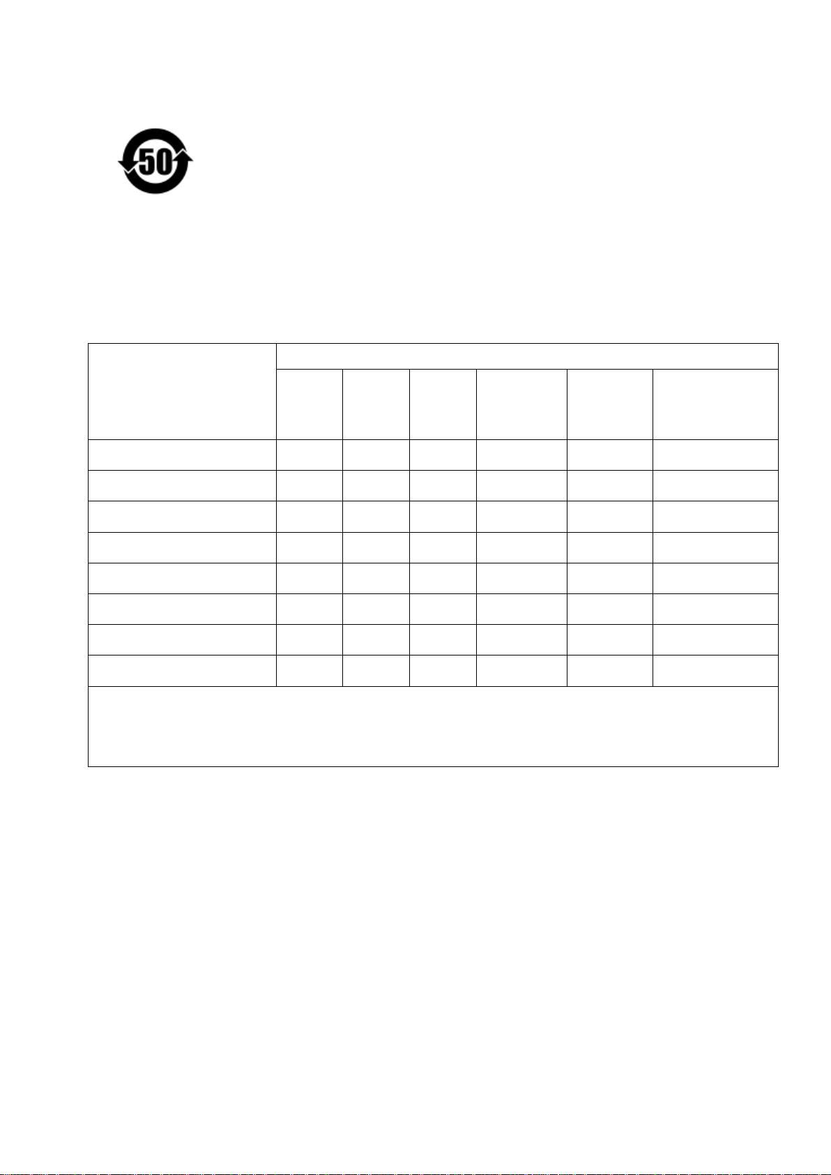
SJ/T 11364-2006
本产品符合中国 RoHS 标准。以下表格标示此产品中某有毒物质的含量符合中国 RoHS 标准规定的限量
要求。
本产品上会附有”环境友好使用期限”的标签,此期限是估算这些物质”不会有泄漏或突变”的年限。本产
品可能包含有较短的环境友好使用期限的可替换元件,像是电池或灯管,这些元件将会单独标示出来。
部件名称
壳体
显示
印刷电路板
金属螺帽
电缆组装
风扇组装
电力供应组装
电池
有毒有害物质或元素
铅
(Pb)
O
O
O
O
O
O
O
O
汞
(Hg)
O O O O
O O O O
O O O O
O O O O
O O O O
O O O O
O O O O
O O O O O
镉
(Cd)
六价铬
(CR(VI))
多溴联苯
(PBB)
多溴二苯醚
(PBDE)
O
O
O
O
O
O
O
O: 表示该有毒有害物质在该部件所有物质材料中的含量均在 SJ/T11363-2006 标准规定的限量要求以下。
X: 表示该有毒有害物质至少在该部件的某一均质材料中的含量超出 SJ/T11363-2006 标准规定的限量要求。
6
Page 7

Symbols in this document
Warning
failure to follow the instructions could result in data damage, disk
This icon indicates the instructions must be strictl y followed. Failure
to do so could result in injury to human body or death.
This icon indicates the action may lead to disk clear ance or loss OR
Caution
damage, or product damage.
7
Page 8

Table of Contents
Contents
Table of Contents ............................................................................................... 8
Safety Warnings ............................................................................................... 10
Chapter 1. CPU and Memory Specifications ................................................... 11
Chapter 2. Power Button and Reset Button Behavior .................................... 34
Chapter 3. USB One Touch Copy .................................................................... 35
Chapter 4. LED and Alarm Buzzer Specifications ........................................... 36
Chapter 5. Upgrade Memory on QNAP Turbo NAS (RAM Module Installation) 39
5.1 TS-453BMINI, TS-453MINI (4-BAY) ............................................................. 39
5.2 TBS-453A ............................................................................................ 41
5.3 TS-451S, TS-531P, TS-531X, TS-651, TS-831X, TS-851, TS-X53/X53S PRO,
TS-563, TVS-882S, TVS-882ST, TVS-X63, TS-X53ASERIES (2/4/6/8-BAY) ................... 43
5.4 TS-1635 .............................................................................................. 44
5.5 TVS-473, TVS-673, TVS-873 ................................................................... 48
5.6 TS-431U, TS-451U, TS-X53U, TS-X63USERIES (4/8/12-BAY) ........................... 50
5.7 TS-251+, TS-251, TS-451+, TS-451, TS-251A, TS-451A ............................. 52
5.8 IS-453S .............................................................................................. 55
Chapter 6. Network Expansion Card Installation ........................................... 58
6.1 TVS-463, TS-531P, TS-531X, TVS-663, TS-831X, TVS-863, TS-563, TS-879 PRO,
TS-1079 PRO, TS-463U, TS-463U-RP .................................................................. 58
6.2 TS-1635 .............................................................................................. 62
6.3 TVS-473, TVS-673, TVS-873 ................................................................... 66
6.4 TS-463U, TS-463U-RP, TVS-471U ............................................................ 69
6.5 TS-863U, TS-863U-RP, TS-1263U, TS-1263U-RP ........................................ 73
Chapter 7. Install and Hot-swap Hard Drives ................................................ 76
7.1 INSTALL HARD DRIVES ............................................................................... 76
7.1.1. TS-x51, TS-x51A, TVS-x63, TS-56 3, TS-x53 Pro, TS-651, TS-831X, TS-851,
TS-531X, TS-531P, TS-x53A .......................................................................... 76
7.1.2. TS-1635 ....................................................................................... 78
7.1.3. TS-453Bmini, TS-453Mini ................................................................ 80
7.1.4. TVS-473, TVS-673, TVS-873 ............................................................ 83
7.1.5. TS-112P, TS-212P and TS-251C ....................................................... 86
8
Page 9

7.1.6.
7.1.7. IS-453S ........................................................................................ 91
7.2 HARD-SWAP HARD DRIVES .......................................................................... 94
Chapter 8. Install M.2 SSDs ........................................................................... 97
8.1 M.2 SSD HEAT SINK INSTALLATION ............................................................... 97
8.2 M.2 SSD INSTALLATION ............................................................................. 97
8.2.1 TBS-453A ..................................................................................... 97
8.2.2 TVS-473, TVS-673, TVS-873 ............................................................ 99
Chapter 9. RAID Recovery ........................................................................... 102
Chapter 10. Use the LCD Panel ...................................................................... 104
Chapter 11. Install Power Supply Unit ........................................................... 110
11.1 1U TURBO NAS WITH HOT-SWAPPABLE PSU ................................................... 110
11.2 2U/3U TURBO NAS (TS-853U-RP, TS-1253U-RP ONLY) ................................. 111
Technical Support .......................................................................................... 114
TAS-168, TAS-268, TS-128, TS-228 .................................................. 88
GNU GENERAL PUBLIC LICENSE ..................................................................... 115
Appendix A: Product Compliance Class ........................................................... 128
9
Page 10
Safety Warnings
1. The NAS can operate normally in a temperature range of 0ºC–40ºC (or up to 35ºC
depending on individual product specifications)with relative humidity of 0% –95%.
Please make sure the environment is well-ventilated.
2. The power cord and devices connected to the NAS must provide correct supply voltage
(100W, 90–264V).
3. Do not place the NAS in direct sunli ght or near che micals. Ma ke sure the tempe rat ure
and humidity of the environment are in optimized level.
4. Unplug the power cord and all connected cables before cleaning. Wipe the NAS with a
dry towel. Do not use chemical or aerosol to clean the NAS.
5. Do n ot place any objects on the NAS for the server’s normal operation and to avoid
overheat.
6. Use the flat head screws in the product package to lock the hard di sks in the NAS when
installing hard disks for proper operation.
7. Do n ot place th e NAS near any liquid.
8. Do not place the NAS on any uneven surface to avoid falling off and damage.
9. Make sure the voltage is correct in the location where the NAS is installed. Contact the
distributor or the local power supply company for the information.
10. Do not place any object on the power cord.
11. Do not attempt to repair the NAS in any occasions. Improper disassembly of the
product may expose the users to electric shock or other risks. For any enquiries,
please contact the distributor.
12. The chassis NAS models should only be installed in the server room and mai ntained by
the authorized server manager or IT administrator. The server room is locked by key or
keycard access and only certified staff is allowed to enter the server room.
Warning:
Danger of explosion if battery is incorrectly replaced. Replace only with the same or
equivalent type recommended by the manufacturer. Dispose of used batteries
according to the manufacturer’s instructions.
Do NOT touch the fan inside the system to avoid serious injuries.
10
Page 11

Chapter 1. CPU and Memory Specifications
Caution: Modifying the hardware, software, or firmware of the QNAP products will
void the warranty. QNAP is not responsible for any form of damage or loss of data caused
by modding the QNAP products. Users should bear their own risks of all sorts of possible
data loss or system instabilities due to cha nging the hardw are parts, modif ying the default
system firmware or installing any unauthorized third party applications on QNAP products.
System TS-112P TS-212P
CPU Marvell 1.6GHz Marvell 1.6GHz
Memory 512MB DDR2 512MB DDR2
Flash 16MB 16MB
Memory
replaceable
Number of RAM
slots
Number of hard
drive slots
System TS-128 TS-228
CPU
Memory
Flash
Memory
replaceable
Number of RAM
slots
Number of hard
drive slots
- -
- -
1 2
Dual-core ARM®v7
1.1GHz
1GB DDR3
4GB
-
-
- -
1 (3.5” HDDs only) 2 (3.5” HDDs only)
Dual-core ARM®v7
1.1GHz
1GB DDR3
4GB
11
Page 12

System TAS-168 TAS-268
Dual-core Realtek
Dual-core Realtek
CPU
Memory
Flash
Memory
1.1GHz
2GB DDR3
4GB
-
1.1GHz
2GB DDR3
4GB
-
replaceable
Number of RAM
-
-
slots
Number of hard
1 (3.5” HDDs only) 2 (3.5” HDDs only)
drive slots
✔(QNAP remote
✔(QNAP remote
IR sensor
control: RM-IR003)
control: RM-IR003)
System TS-131 TS-231
CPU
Dual-core
Freescale
TM
1.2GHz
Dual-core
Freescale
TM
1.2GHz
Memory
Flash
Memory
512MB DDR3 512MB DDR3
512MB 512MB
- -
replaceable
Number of RAM
- -
slots
Number of hard
1 2
drive slots
12
Page 13

System TS-431 TS-431U
CPU
Memory
Flash
Memory
Dual-core
Freescale
TM
1.2GHz
512MB DDR3 1GB DDR3
512MB 512MB
- -
Dual-core
Freescale
replaceable
Number of RAM
- -
slots
Number of hard
4 4
drive slots
System TS-231+ TS-431+
Annapurna Labs
Alpine AL-212
Annapurna Labs
Alpine AL-212
CPU
Dual-core 1.4GHz
Cortex-A15
Dual-core 1.4GHz
Cortex-A15
TM
1.2GHz
Memory
Flash
1GB DDR3 1GB DDR3
512MB 512MB
Memory
- -
replaceable
Number of RAM
- -
slots
Number of hard
2 4
drive slots
PCI-E expansion
- -
slot
Built-in 10GbE LAN
- -
ports
13
Page 14

System TS-531P TS-531X TS-831X
core Annapurna
nnapurna
nnapurna
(Expandable RAM, up
(Expandable RAM, up
(Expandable RAM, up
core Annapurna
(Expandable RAM, up
CPU
Memory
Flash
Memory
replaceable
Number of RAM
slots
Number of hard
drive slots
PCI-E expansion
slot
Built-in 10GbE LAN
ports
QuadLabs Alpine AL-314
1.4GHz Cortex-A15
2GB/8GB DDR3
to 16GB)
Quad-core A
Labs Alpine AL-314
1.4GHz Cortex-A15
2GB/8GB DDR3
to 16GB)
Quad-core A
Labs Alpine AL-314
1.4GHz Cortex-A15
8GB/16GB DDR3
to 16GB)
512MB 512MB 512MB
✔ (Compatible with
DDR3 RAM)
✔ (Compatible with
DDR3 RAM)
✔ (Compatible with
DDR3 RAM)
2 (SODIMM) 2 (SODIMM) 2 (SODIMM)
5 5 8
1 1 1
- 2 x SFP+ 2 x SFP+
System TS-1635 HS-210
Quad-
CPU
Labs Alpine AL-514
Marvell 1.6GHz
1.7GHz Cortex-A15
8GB/16GB DDR3
Memory
512MB DDR3
to 16GB)
Flash
Memory
replaceable
Number of RAM
512MB
✔ (Compatible with
DDR3 RAM)
16MB
-
-
2 (SODIMM)
slots
Number of hard
16 2
drive slots
PCI-E expansion
1
slot
Built-in 10GbE LAN
ports
14
2 x SFP+
Page 15

(Expandable RAM, up
(Expandable RAM, up
(Expandable RAM, up
System TS-451U TS-453U TS-453U-RP
Dual-core
®
Intel
Celeron™
Quad-core
®
Intel
Celeron™
Quad-core
®
Intel
Celeron™
CPU
2.41GHz (up to
2.58GHz)
1GB DDR3L
Memory
to 8GB)
2.0GHz (up to
2.42GHz)
4GB/8GB DDR3L
(Expandable RAM, up
to 8GB)
2.0GHz (up to
2.42GHz)
4GB/8GB DDR3L
to 8GB)
Flash 512MB (USB DOM) 512MB (USB DOM) 512MB (USB DOM)
Memory
replaceable
✔ (Compatible with
DDR3L RAM)
✔ (Compatible with
DDR3L RAM)
✔ (Compatible with
DDR3L RAM)
Number of RAM
2 (SODIMM) 2 (SODIMM) 2 (SODIMM)
slots
Number of hard
4 4 4
drive slots
Power supply unit 250W 250W 2 x 250W
System TS-853U TS-853U-RP
Quad-core
®
Intel
Celeron™
Quad-core
®
Intel
Celeron™
CPU
2.0GHz (up to
2.42GHz)
4GB/8GB DDR3L
Memory
to 8GB)
2.0GHz (up to
2.42GHz)
4GB/8GB DDR3L
(Expandable RAM, up
to 8GB)
Flash 512MB (USB DOM) 512MB (USB DOM)
Memory
replaceable
✔ (Compatible with
DDR3L RAM)
✔ (Compatible with
DDR3L RAM)
Number of RAM
2 (SODIMM) 2 (SODIMM)
slots
Number of hard
8 8
drive slots
Power supply unit 250W 2 x 250W
15
Page 16

System TS-1253U TS-1253U-RP
(Expandable RAM, up
Quad-core
®
Intel
Celeron™
Quad-core
®
Intel
Celeron™
CPU
2.0GHz (up to
2.42GHz)
4GB/8GB DDR3L
Memory
to 8GB)
2.0GHz (up to
2.42GHz)
4GB/8GB DDR3L
(Expandable RAM, up
to 8GB)
Flash 512MB (USB DOM) 512MB (USB DOM)
Memory
replaceable
✔ (Compatible with
DDR3L RAM)
✔ (Compatible with
DDR3L RAM)
Number of RAM
2 (SODIMM) 2 (SODIMM)
slots
Number of hard
12 12
drive slots
Power supply unit 250W 2 x 250W
System IS-453S
Quad-core
CPU
Intel® Atom™
1.91GHz
IS-453S-2G: 2GB
DDR3L
Memory
IS-453S-8G: 8GB
DDR3L
Flash 512MB (USB DOM)
CPU replaceable -
✔ (Compatible with
Memory
DDR3L-1333/1600S
replaceable
ODIMM RAM)
Number of RAM
2 (SODIMM)
slots
Number of hard
4 (2.5" only)
drive slots
16
Page 17

System TS-251C
(Expandable RAM, up
(Expandable RAM, up
(Expandable RAM, up
TS-251/
TS-251-4G
TS-251A-2G /
TS-251A-4G
CPU
Memory
Flash
Memory
replaceable
Number of RAM
slots
Number of hard
drive slots
IR sensor
Dual-core
®
Intel
Celeron™
2.41GHz (up to
2.58GHz)
Dual-core
®
Intel
Celeron™
2.41GHz (up to
2.58GHz)
1GB DDR3L 1GB / 4GB DDR3L
Dual-core
®
Intel
Celeron™
1.6GHz (up to
2.48GHz)
2GB / 4GB DDR3L
(Expandable RAM, up
512MB
to 8GB)
512MB 512MB
✔ (Compatible with
to 8GB)
✔ (Compatible with
DDR3L RAM)
DDR3L-1600 RAM)
- 2(SODIMM) 2(SODIMM)
2 (3.5” HDDs only) 2 2
✔(QNAP remote
control: RM-IR002)
✔(QNAP remote
control: RM-IR002)
✔(QNAP remote
control: RM-IR002)
System
TS-451 /
TS-451-4G
Dual-core
®
Intel
Celeron™
TS-451A-2G /
TS-451A-4G
Dual-core
®
Intel
Celeron™
TS-451S
Dual-core
®
Intel
CPU
2.41GHz (up to
2.58GHz)
1GB / 4GB DDR3L
Memory
to 8GB)
1.6GHz (up to
2.48GHz)
2GB / 4GB DDR3L
(Expandable RAM, up
to 8GB)
2.41GHz (up to
2.58GHz)
1GB DDR3L
to 8GB)
Flash 512MB 512MB 512MB
Memory
replaceable
✔ (Compatible with
DDR3L RAM)
✔ (Compatible with
DDR3L-1600 RAM)
✔ (Compatible with
DDR3L RAM)
Number of RAM
2 (SODIMM) 2(SODIMM) 2 (SODIMM)
slots
Number of hard
4 2 4 (2.5” only)
drive slots
Celeron™
IR sensor
17
✔ (QNAP remote
control: RM-IR002)
✔(QNAP remote
control: RM-IR002)
✔ (QNAP remote
control: RM-IR002)
Page 18

18
Page 19

System
(Expandable RAM, up
TS-651 /
TS-651-4G
TS-851 /
TS-851-4G
Dual-core
®
Intel
Celeron™
Dual-core
®
Intel
CPU
2.41GHz (up to
2.58GHz)
1GB / 4GB DDR3L
Memory
to 8GB)
2.41GHz (up to
2.58GHz)
1GB / 4GB DDR3L
(Expandable RAM, up
to 8GB)
Flash 512MB 512MB
Memory
replaceable
✔ (Compatible with
DDR3L RAM)
✔ (Compatible with
DDR3L RAM)
Number of RAM
2 (SODIMM) 2 (SODIMM)
slots
Number of hard
6 8
drive slots
✔ (QNAP remote
✔ (QNAP remote
IR sensor
control: RM-IR002)
control: RM-IR002)
Celeron™
HS-251 /
System HS-251+
HS-251-2G
Quad-core
®
Intel
Celeron™
Dual-core
®
Intel
Celeron™
CPU
2.0GHz (up to
2.42GHz)
2.41GHz (up to
2.58GHz)
Memory 2GB DDR3L 1GB / 2GB DDR3L
Flash 512MB 512MB
CPU replaceable
- -
Memory
- -
replaceable
Number of RAM
- -
slots
Number of hard
2 2
drive slots
IR sensor
19
✔ (QNAP remote
control: RM-IR002)
✔ (QNAP remote
control: RM-IR002)
Page 20

20
Page 21

TBS-453A-4G/
(up to
TBS-453A-8G/
TBS-453A-4G-1TB
TBS-453A-8G-1TB
System
/TBS-453A-4G-51
2GB
Quad-core
®
Intel
Celeron™
/TBS-453A-8G-51
2GB
Quad-core
®
Intel
Celeron™
CPU
N3150 1.6GHz
2.08GHz)
N3150 1.6GHz (up to
2.08GHz)
Memory 4GB DDR3L 8GB DDR3L
Flash 4GB 4GB
CPU replaceable
Memory
replaceable
- -
✔ (Compatible with
DDR3L RAM)
✔ (Compatible with
DDR3L RAM)
Number of RAM
2 (SODIMM) 2 (SODIMM)
slots
Number of hard
4 4
drive slots
✔ (QNAP remote
IR sensor
control: RM-IR002 &
RM-IR003)
✔ (QNAP remote
control: RM-IR002 &
RM-IR003)
21
Page 22

System
CPU
TS-251+-2G /
TS-251+-8G
®
Quad-core Intel
Celeron™
2.0GHz (up to 2.42GHz)
TS-253 Pro /
TS-253 Pro-8G
Quad-core Intel® Celeron™
2.0GHz (up to 2.42GHz)
2GB / 8GB DDR3L
2GB / 8GB DDR3L (Expandable
Memory
(Expandable RAM, up to 8GB)
RAM, up to 8GB)
Flash 512MB 512MB
Memory
replaceable
✔ (Compatible with
DDR3L-1333/1600 RAM)
✔ (Compatible with
DDR3L-1333/1600 RAM)
Number of
2(SODIMM) 2(SODIMM)
RAM slots
Number of
hard drive
2 2
slots
✔ (QNAP remote control:
✔ (QNAP remote control:
IR sensor
RM-IR002)
RM-IR002)
System
TS-453Bmini-4G /
TS-453Bmini-8G
Quad-core Intel
® Celeron™ J3455
TS-453mini-2G /
TS-453mini-8G
Quad-core Intel® Celeron™ J1900
CPU
1.5 GHz (up to 2.3 GHz)
2.0GHz (up to 2.42GHz)
4GB / 8GB DDR3L
2GB / 8GB DDR3L
Memory
(Expandable RAM, up t o 8GB)
(Expandable RAM, up to 8GB)
Flash 512MB 512MB
Memory
replaceable
✔ (Compatible with DDR3L
RAM)
✔ (Compatible with
DDR3L-1333/1600 RAM)
Number of
2 (SODIMM) 2 (SODIMM)
RAM slots
Number of
hard drive
4 4
slots
✔ (QNAP remote control:
✔ (QNAP remote control:
IR sensor
RM-IR002)
RM-IR002)
22
Page 23

System
(Expandable RAM, up
(Expandable RAM, up
TS-451+-2G /
TS-451+-8G
TS-453 Pro /
TS-453 Pro-8G
TS-653 Pro /
TS-653 Pro-8G
Quad-core
®
Intel
Celeron™
Quad-core
®
Intel
Celeron™
Quad-core
®
Intel
CPU
2.0GHz (up to
2.42GHz)
2GB / 8GB DDR3L
Memory
to 8GB)
2.0GHz (up to
2.42GHz)
2GB / 8GB DDR3L
(Expandable RAM, up
to 8GB)
2.0GHz (up to
2.42GHz)
2GB / 8GB DDR3L
to 8GB)
Flash 512MB 512MB 512MB
Memory
replaceable
✔ (Compatible with
DDR3L RAM)
✔ (Compatible with
DDR3L RAM)
✔ (Compatible with
DDR3L RAM)
Number of RAM
2 (SODIMM) 2 (SODIMM) 2 (SODIMM)
slots
Number of hard
4 4 6
drive slots
LCD panel
-
✔ (QNAP remote
✔ ✔
✔ (QNAP remote
✔ (QNAP remote
IR sensor
control: RM-IR002)
control: RM-IR002)
control: RM-IR002)
Celeron™
23
Page 24

System
(Expandable RAM, up
(Expandable RAM, up
TS-853 Pro /
TS-853 Pro-8G
TS-453S Pro
(Formerly the
SS-453 Pro)
TS-853S
Pro(Formerly the
SS-853 Pro)
Quad-core
®
Intel
Celeron™
Quad-core
®
Intel
Celeron™
Quad-core
®
Intel
CPU
2.0GHz (up to
2.42GHz)
2GB / 8GB DDR3L
Memory
to 8GB)
2.0GHz (up to
2.42GHz)
4GB DDR3L
(Expandable RAM, up
to 8GB)
2.0GHz (up to
2.42GHz)
4GB DDR3L
to 8GB)
Flash 512MB 512MB 512MB
Memory
replaceable
✔ (Compatible with
DDR3L RAM)
✔ (Compatible with
DDR3L RAM)
✔ (Compatible with
DDR3L RAM)
Number of RAM
2(SODIMM) 2(SODIMM) 2(SODIMM)
slots
Number of hard
8 4 (2.5” only) 8 (2.5” only)
drive slots
LCD panel ✔
✔ (QNAP remote
-
✔ (QNAP remote
✔
✔ (QNAP remote
IR sensor
control: RM-IR002)
control: RM-IR002)
control: RM-IR002)
Celeron™
24
Page 25

System
(Expandable RAM, up
(Expandable RAM, up
TS-563-4G /
TS-563-8G
TVS-463-4G /
TVS-463-8G
TVS-663-4G /
TVS-663-8G
Quad-core AMD
Quad-core AMD
Quad-core AMD
CPU
2.0GHz
4/8 GB DDR3L
Memory
to 16GB)
2.4GHz
4/8 GB DDR3L
(Expandable RAM, up
to 16GB)
2.4GHz
4/8 GB DDR3L
to 16GB)
Flash 512MB 512MB 512MB
Memory
replaceable
✔ (Compatible with
DDR3L-1600 RAM)
✔ (Compatible with
DDR3L-1600 RAM)
✔ (Compatible with
DDR3L-1600 RAM)
Number of RAM
2(SODIMM) 2(SODIMM) 2(SODIMM)
slots
Number of hard
5 4 6
drive slots
PCI-E expansion
1 1 1
slot
HDMI
LCD panel
-
-
✔ ✔
✔ ✔
IR sensor
-
✔ (QNAP remote
control: RM-IR002)
✔ (QNAP remote
control: RM-IR002)
25
Page 26

System
TVS-863-4G /
TVS-863-8G
TVS-863+-8G /
TVS-863+-16G
Quad-core AMD
Quad-core AMD
CPU
Memory
2.4GHz
4/8 GB DDR3L
(Expandable RAM, up to
16GB)
2.4GHz
8/16 GB DDR3L
(Expandable RAM, up to
16GB)
Flash 512MB 512MB
Memory
replaceable
✔ (Compatible with
DDR3L-1600 RAM)
✔ (Compatible with
DDR3L-1600 RAM)
Number of RAM
2(SODIMM) 2(SODIMM)
slots
Number of hard
8 8
drive slots
PCI-E expansion
1 (Pre-installed 1-port
1
slot
10GbE NIC)
HDMI ✔ ✔
LCD panel ✔ ✔
IR sensor
✔(QNAP remote control:
RM-IR002)
✔ (QNAP remote
control: RM-IR002)
26
Page 27

System
(Expandable RAM, up
(Expandable RAM, up
TS-253A-4G /
TS-253A -8G
TS-453A -4G /
TS-453A -8G
TS-653A -4G /
TS-653A -8G
Quad-core Intel®
Celeron® N3150
Quad-core Intel®
Celeron® N3150
Quad-core Intel®
Celeron® N3150
CPU
1.6GHz (up to
2.08GHz)
4/8 GB DDR3L
to 8GB)
Memory
1.6GHz (up to
2.08GHz)
4/8 GB DDR3L
to 8GB)
1.6GHz (up to
2.08GHz)
4/8 GB DDR3L
(Expandable RAM, up
to 8GB)
Flash 512MB 512MB 512MB
Memory
replaceable
✔ (Compatible with
DDR3L-1600 RAM)
✔ (Compatible with
DDR3L-1600 RAM)
✔ (Compatible with
DDR3L-1600 RAM)
Number of RAM
2(SODIMM) 2(SODIMM) 2(SODIMM)
slots
Number of hard
2 4 6
drive slots
PCI-E expansion
- - -
slot
HDMI 2 2 2
LCD panel
-
✔ (QNAP remote
✔ ✔
✔ (QNAP remote
✔ (QNAP remote
IR sensor
control: RM-IR002)
control: RM-IR002)
control: RM-IR002)
27
Page 28

System
(Expandable RAM, up
TS-853A -4G /
TS-853A -8G
Quad-core Intel®
CPU
Celeron® N3150
1.6GHz (up to
2.08GHz)
4/8 GB DDR3L
Memory
to 8GB)
Flash 512MB
Memory
replaceable
✔ (Compatible with
DDR3L-1600 RAM)
Number of RAM
2(SODIMM)
slots
Number of hard
8
drive slots
PCI-E expansion
-
slot
HDMI 2
LCD panel
IR sensor
✔
✔ (QNAP remote
control: RM-IR002)
28
Page 29

System
8GB DDR4 (Expandable RAM, up
TVS-882S-i5-8G TVS-882S-i7-16G
CPU
Memory
Flash
Memory
replaceable
Number of RAM
slots
Number of drive
slots
Quad-core Intel® Core
1.9GHz
to 32GB)
✔ (Compatible with DDR4 RAM)
8 x 2.5” SATA 6Gb/s
TM
i5
16GB DDR4 (Expandable RAM,
512MB
2(SODIMM)
Quad-core Intel® Core
2.6GHz
up to 32GB)
TM
i7
PCI-E expansion
slot
HDMI
LCD panel
IR sensor
1 x PCIe Gen3 (x8) + 1 x PCIe Gen3 (x4)
1
✔
✔ (QNAP remote control: RM-IR002)
29
Page 30

System
TVS-882ST2-i5-8G TVS-882ST2-i7-16G
CPU
Memory
Flash
Memory replaceable
Number of RAM slots
Number of drive slots
Quad-core Intel® Core
TM
i5
1.9GHz
8GB DDR4 (Expandable RAM,
up to 32GB)
512MB
✔ (Compatible with DDR4 RAM)
2(SODIMM)
8 x 2.5” SATA 6Gb/s
Quad-core Intel® Core
2.6GHz
16GB DDR4 (Expandable
RAM, up to 32GB)
TM
i7
PCI-E expansion slot
HDMI
LCD panel
IR sensor
Thunderbolt
10GbE LAN
1 x PCIe Gen3 (x8) + 1 x PCIe Gen3 (x4)
Note: These two expansion slots are occupied by a Thunderbolt™ 2 and a
USB 3.1 expansion card..
1
✔
✔ (QNAP remote control: RM-IR002)
2 x Thunderbolt™ 2 ports
2 x 10GbE SFP+ LAN ports
30
Page 31

(Expandable RAM, up
(Expandable RAM, up
System TS-463U TS-463U-RP TS-863U
Quad-core AMD
Quad-core AMD
Quad-core AMD
CPU
2.0GHz
4 GB DDR3L
Memory
to 16GB)
2.0GHz
4 GB DDR3L
(Expandable RAM, up
to 16GB)
2.0GHz
4 GB DDR3L
to 16GB)
Flash 512MB 512MB 512MB
Memory
replaceable
✔ (Compatible with
DDR3L-1600 RAM)
✔ (Compatible with
DDR3L-1600 RAM)
✔ (Compatible with
DDR3L-1600 RAM)
Number of RAM
2(SODIMM) 2(SODIMM) 2(SODIMM)
slots
Number of hard
4 4 8
drive slots
PCI-E expansion
slot
HDMI
LCD panel
1 (Pre-installed
LAN-10G1SR-D NIC)
1 (Pre-installed
LAN-10G1SR-D NIC)
- - -
-
- -
1 (Pre-installed
LAN-10G1SR-U NIC)
31
Page 32

System TS-863U-RP TS-1263U TS-1263U-RP
(Expandable RAM, up
(Expandable RAM, up
Quad-core AMD
Quad-core AMD
Quad-core AMD
CPU
2.0GHz
4 GB DDR3L
Memory
to 16GB)
2.0GHz
4 GB DDR3L
(Expandable RAM, up
to 16GB)
2.0GHz
4 GB DDR3L
to 16GB)
Flash 512MB 512MB 512MB
Memory
replaceable
✔ (Compatible with
DDR3L-1600 RAM)
✔ (Compatible with
DDR3L-1600 RAM)
✔ (Compatible with
DDR3L-1600 RAM)
Number of RAM
2(SODIMM) 2(SODIMM) 2(SODIMM)
slots
Number of hard
8 12 12
drive slots
PCI-E expansion
slot
HDMI
LCD panel
1 (Pre-installed
LAN-10G1SR-U NIC)
1 (Pre-installed
LAN-10G1SR-U NIC)
- - -
-
- -
1 (Pre-installed
LAN-10G1SR-U NIC)
32
Page 33

System
CPU
Memory
Flash
Memory
replaceable
Number of
RAM slots
TVS-473 TVS-673 TVS-873
AMD R-Series RX-421BD 2.1 GHz APU, Turbo Core up to 3.4 GHz
8GB DDR4
(Expandable RAM, up
to 64GB)
16GB DDR4
(Expandable RAM, up
to 64GB)
64GB DDR4
(Expandable RAM, up
to 64GB)
512MB
✔ (Compatible with DDR4 RAM)
4 (SODIMM)
Number of
drive slots
PCI-E
expansion slot
HDMI
LCD panel
IR sensor
USB 3.1
4 x 3.5”/2.5” SATA
6Gb/s
6 x 3.5”/2.5” SATA
6Gb/s
8 x 3.5”/2.5” SATA
6Gb/s /s
2 x PCIe Gen3 (x4)
*One slot is pre-installed with a dual-port USB 3.1 PCIe card.
2
✔
✔ (QNAP remote control: RM-IR004)
2 x USB 3.1 Gen 2 Ports
33
Page 34

Chapter 2. Power Button and Reset Button Behavior
Power button: Press to turn on or turn off.
System
All models
Reset button: Press to reset the system settings.
System
All models 3 sec 10 sec
Basic system reset (3 sec)
Press the reset button for 3 seconds, a beep sound will be heard. The following settings are
reset to default:
System administration password: admin
TCP/IP configuration: Obtain IP address settings automatically via DHCP
TCP/IP configuration: Disable Jumbo Frame
Power button
(Turn on)
Press once 1.5 sec
Basic system reset
(1 beep)
Power button
(Hardware turn
off)
Advanced system reset
(2 beeps)
Power button
(Force turn off)
5 sec
TCP/IP configuration: If port trunking is enabled (dual LAN models only), the port
trunking mode will be res e t to “Active Backup (Failover)”.
System Port: 8080 (system service port)
Security Level: Low (Allow all co nnections)
LCD panel password: (blank)*
VLAN will be disabled
*This feature is only provid e d by the NAS models with LCD panels. Please
visit
http://www.qnap.comfor details.
Advanced system reset (10 sec)
Press and hold the reset button for 10 seconds. You will hear two beeps; one at the three
second mark and another at the ten second marks. The NAS will reboot and reset the
system settings back to default. Settings such as users, user groups, and the network
share folders previously created will be cleared. Default network shares will be restored
(not applicable to 1-bay NAS models). To retrieve the old data after the advanced system
reset, recreate the same network share folders on the NAS and the data will be accessible
again.
34
Page 35

Chapter 3. USB One Touch Copy
System
Number of seconds (press the one touch copy button to
trigger data copy)
All NAS models 0.5 sec
Data Copy by the Front USB Port
The NAS supports instant data copy to or from a USB device using the front one touch copy
button. To use this function, follow the steps below:
1. Make sure at least one hard drive is installed and configured on the NAS.
2. Configure the behavior of the one touch copy button on “Backup Station/ Hybrid
Backup Sync” > “External Backup” > “USB One Touch Copy”.
3. Connect the USB storage device to the front USB port on the NAS.
4. Press the one touch copy button. The US B L E D wil l fl ash. The data w ill be ba ck ed up .
Note:
This feature adopts incremental backup. Afte r the first time data back up, the NAS only
copies the changed files since the last backup.
This feature is only available on certain NAS models. Please refer to the product
specification table for details at www.qnap.com.
35
Page 36

Chapter 4. LED and Alarm Buzzer Specifications
Flashes green
seconds
The LED indicators of the NAS indicate the system status and i nformation. When the NAS is
turned on, check the following items to make sure the system status is normal. Note that
the following LED infor mation is applicable only when users have properly installed the hard
drive, and connected the NAS to the network and the power supply.
LED Color LED Status Description
1. T he hard drive on the NAS is being
formatted.
System
Status
Flashes green
and red
alternately
every 0.5 sec
Red
Red/
Green
2. The NAS is being initialized.
3. The system firmware is being updated.
4. RAID rebuilding is in process.
5. Online RAID Capacity Expansion is in
process.
6. Online RAID Level Migration is in process.
1. T he hard drive is invalid.
2. T he disk volume has reached its full
capacity.
3. The disk volume is going to be fu ll.
4. The system fan is out of function.
5. An error occurs when accessing
(read/write) the disk data.
6. A bad sector is detected on the hard
drive.
7. The NAS is in degraded read-only mode
(2 member drives fail in a RAID 5 or RAID
6 configuration, the disk data can still be
read).
8. Hardware self-test error.
1
for details at www.qnap.com.
36
Flashes red
every 0.5 sec
Flashes green
every 0.5 sec
every 2
The NAS is in degraded mode (one member
drive fails in RAID 1, RAID 5 or RAID 6
configuration).
1. The NAS is starting up.
2. The NAS is not configured.
3. A hard disk drive is not formatted.
The NAS is in S3 sleep mode1.
Green The NAS is ready.
Off
This feature is only available on certain NAS models. Please refer to the product specification table
All the hard disk drives on the NAS are in
standby mode.
Page 37

LED Color LED Status Description
The disk data is being accessed from the
the process.
NAS has finished c opying the data to
LAN Orange
10GbE2 Green
HDD
Red/
Green
USB Blue
Orange
Flashes
orange
Green
network and a read/write error occurs during
The NAS is being accessed from the network.
The 10GbE network expansion card is
installed.
Off No 10GbE network expansion card is installed.
Flashes red
The disk data is being accessed and a
read/write error occurs during the process.
Red A hard disk drive read/write error occurs.
Flashes green The disk data is being accessed.
Green The hard disk drive can be accessed.
1. A USB device (connected to the front USB
port) is being detected.
2. A USB device (connected to the front USB
Flashes blue
every 0.5 sec
port) is being removed from the NAS.
3. The USB device (connected to the front
USB port of the NAS) is being accessed.
4. Th e data is being copied to or from the
external USB or eSATA device.
Blue
A front USB device is detected (after the
device is mounted).
1. No US B d evice is detected.
Off
2. The
or from the USB device connected to the
front USB port.
Flashes The eSATA device is being accessed.
eSATA3 Orange
Off No eSATA device can be detected.
2
The 10 GbE network expansion function is only supported certain NAS models. Please refer to the
product specification table for details at www.qnap.com.
3
This feature is only available on certain NAS models. Please refer to the product specification table
for details at www.qnap.com.
37
Page 38

Beep alarm (for all NAS models)
1. The NAS is starting up.
updated.
The beep alarm can be disabled in “System Administration” > “Hardware Settings”.
Beep sound Number of Times Description
2. The NAS is being shut down
(software shutdown).
Short beep (0.5 sec) 1
3. The user presses the reset button to
reset the NAS.
4. The system firmware has been
The user tries to copy the NA S data to the
Short beep (0.5 sec) 3
external storage device from the front
USB port, but the data cannot be copied.
Long beep (1.5 sec) 3, every 5 min The system fan is out of function.
1. T he disk volume is going to be full.
2. T he disk volume has reached its full
capacity.
2
3. The hard drives on the NAS are in
degraded mode.
4. The user starts the hard drive
Long beep (1.5 sec)
rebuilding process.
5. A hard drive is plugged in or out.
1
1. The NAS is turned off by force
shutdown (hardware shutdown).
2. The NAS has been turned on
successfully and is ready.
38
Page 39

Chapter 5. Upgrade Memory on QNAP Turbo NAS (RAM Module
Installation)
Warning:
The following instructions should only be performed by an authorized and trained
technician.
Strictly adhere to the instructions to install a RAM module on the NAS. F ailure to do so
could result in injury to human body or death.
Before starting, please ensure that you turn off the NAS, disconnect the power
adaptor, network cable(s), and also remove any other device/cable that is attached to
the NAS.
Please ensure that you wear an antistatic wrist strap during the entire process to
prevent electrostatic discharge. The crocodile clip should be connected to the ground.
When installing more than one memory module, it is recommended to use the same
size and ideally the same type/model in every slot.
QNAP provides different RAM modules (optional purchase) through its resellers for users to
upgrade the NAS memory. Use of non-QNAP RAM modules may cause system instability.
Follow the below steps to install an extra memory module on the NAS to upgrade the
memory.
Follow the steps below to install a R AM module on the NAS.
5.1 TS-453Bmini, TS-453mini (4-bay)
1. Use a flathead screwdriver to loosen the screw on the memory module compartment
at the bottom of the NAS and lift the compartment cover away.
39
Page 40

2. T o remove installed memory modules, pull the retention clips on each side so that the
module tilts up for easy removal.
Note: Always ensure that a memory module is installed in the Primary (red) slot.
If not, then the system will fail to start. The maximum supported memory is 8GB
combined.
3. Slide the memory module to the slot at a 45-degree angle (approximately) and press
the memory module down until it clips into place. Ensure th e memory module sits
40
Page 41

properly with the clips in place.
4. Close the NAS cover and fasten the screw. Reconnect the power and network cables
to the NAS.
5.2 TBS-453A
1. Remove the rubber feet and loosen the four hand screws on the bottom of the NAS.
Then lift the compartment cover away.
2. To remove installed memory modules, pull the retention clips on each side so that the
module tilts up for easy removal.
41
Page 42

Note: Always ensure that a memory module is installed in the Primary (red) slot.
If not, then the system will fail to start. The maximum supported memory is 8GB
combined.
3. Slide the memory module to the slot at a 45-degree angle (approximately) and press
the memory module down unt il it clips into place. Ensure the memory modu le sit s
properly with the clips in place.
4. Close the NAS cover, fasten the four hand screws, and replace the rubber feet.
Reconnect the power and network cables to the NAS.
42
Page 43

5.3 TS-451S, TS-531P, TS-531X, TS-651, TS-831X, TS-851, TS-x53/x53S Pro,
TS-563, TVS-882S, TVS-882ST, TVS-x63, TS-x53Aseries (2/4/6/8-bay)
1. Loosen the three screws on the rear of the NAS.
2. Remove the case cover of the NAS gently.
3. Loc a te the memory slot. Make sure the slot is empty.
Note: For TS-x53/x53S Pro, TS-451S, TS-531P, TS-651, TS-851 and TS-x53A
models, always ensure that a memory module is installed in the Primary slot
(red). If not, then the system will fail to start. The maximum supported memory is
8GB combined.
4. Grasp the edge of the memory module. Align the notch on the gold edge of the module
43
Page 44

with the notch in the memory slot. Slide the memory module to the slot at a 45-degree
angle (approximately).
5. Gently press the memory mod ule into the slot until it is seated fully.
6. Rotate the memory module towards the motherboard until the securing clips clicks into
place.
7. Close the case cover and fasten the screws. Connect the power adaptor and cables
back to the NAS.
8. To check that the memory module is recognized by the NAS, power up the NAS and
login the web interface as an administrator. Go to “System Status”>“System
Information” and check the total memory in “Hardware Information”.
5.4 TS-1635
1. Loosen the screws o n the back of the NAS that are connecting the case cover to the
case.
44
Page 45

2. Gently remove case cover from case.
3. T o remove i nstalled memory modules, gently pull the retention clips outwards on each
side so that the module tilts up at a 45-degree angle for easy removal. Remove module.
45
Page 46

4. Hold the memory module by grasping its edges. Align the notch on the RAM
module with the ridge in the memory socket. Slide the memory module into the
socket at a 45-degree angle. Ensure that the module is firmly inserted into slot.
Note: Memory module must be installed in the primary slot (red outline in photo).
System will fail to start if primary slot is empty. The maximum supported memory per
slot is 8GB.
46
Page 47

5. Gently push the memory module towards the motherboard until the retention clips
lock the memory module in place.
6. Close the case cover and fasten the screws. Connect the power adaptor and cables
to the NAS. Power on NAS.
7. To verify that the memory module has been installed correctly and is being
recognized by the operating system, log into QTS as administrator.
o For QTS 4.3.0 and above: Go to “Control Panel” > “System”> “System
Status”>“Hardware Information” and check for Total memory.
o For QTS 4.2.x and below: Go to “Control Panel” > “System Settings”> “System
Status”>“Hardware Information” and check for Total memory.
47
Page 48

5.5 TVS-473, TVS-673, TV S-873
1. Loosen the screws on the back of the NAS that are connec ting the case cover to the
case.
2. Gently remove case cover from case.
48
Page 49

3. T o remove i nstalled memory modules, gently pull the retention clips outwards on each
side so that the module tilts up at a 30-degree angle for easy removal. Remove module.
4. Hold the memory module by grasping its edges. Align the notch on the RAM module
with the ridge in the memory socket. Slide the memory module into the socket at a
30-degree angle. Ensure that the module i s firmly inserted i nto the socket and that
the retention clamps are secure.
Note: The maximum supported memory is 64GB.
For one SODIMM module, insert memory into slot A2 or B2.
For two SODIMM modules using dual channel, insert memory into A1 and A2, B1 and B2,
or A2 and B2.
For three SODIMM modules, insert memory into A1 and A2 and B2 or B1 and B2 and A2.
49
Page 50

5. Gently push the memory module towards the motherboard until the retention clips
lock the memory module in place.
6. Close the case cover and fasten the screws. Connect the power adaptor and cables
to the NAS. Power on NAS.
7. To verify that the memory module has been installed correctly and is being
recognized by the operating system, log into QTS as administrator and go to
“Control Panel” > “System” > “System Status” > “Hardware Information” and
check for Total memory.
5.6 TS-431U, TS-451U, TS-x53U, TS-x63Useries (4/8/12-bay)
1. Open the NAS.
a. TS-431U, TS-451U, TS-453U, TS-463U series: Loosen all the screws on t he top of
the NAS.
50
Page 51

b. TS-853U, TS-863U, TS-1253U, TS-1263U series: Loosen the two screws on the
rear of the NAS.
2. Open the NAS. Pull the retention clips on each side so that the module tilts up for easy
removal. Remove installed memory modules.
51
Page 52

3. Slide the memory module to th e slot at a 45-degree angle (approximately).
4. Press the memory module down . Make sure the memory module sits in properly with
the clips in place.
Note: For TS-x53U & TS-451U models, always ensure that a memory module is
installed in the primary slot (red box in the below figure,) or the system will fail to
start. The maximum supported memory is 8GB combined.
5. Close the NAS cover and fasten the screws. Connect the power adaptor and cables back
to the NAS.
5.7 TS-251+, TS-251, TS-451+, TS-451, TS-251A, TS-451A
1. Remove the screws on the rear (top and bottom) of the NAS. If you have a 2-bay NAS,
52
Page 53

it will have two screws. A 4-bay NAS will have four.
2. Gently remove the case cover of the NAS by sliding it apart (see the unders ide of the
NAS for visual indicators of the NAS case being locked/unlocked)
3. Remove the four inner screws (two on each side) of the hard drive cage.
4. If it is a 4-bay NAS, you will also need to remove two screws on the top of the hard drive
cage.
53
Page 54

5. Gently remove the hard drive cage from the NAS by lifting it out of its slot.
6. Always ensure that a memory module is installed in the Primary slot (red). If
not, then the system will fail to start. When installing two memory modules, please
ensure that they are the same size and ideally use the same type of RAM for both
memory slots. The maximum supported memory is 8GB combined.
TS-251/TS-451 TS-251A/TS-451A
54
Page 55

7. Reattach the hard drive cage to the NAS. Please ensure that it correctly plugs into the
slot.
8. Secure the hard drive cage by fastening the four inner screws (for the 4-bay NAS,
please fasten the two additional top screws.) Then reattach the case cover of the NAS
by gently sliding it back together.
9. Fasten the two/four screws onto the rear of the NAS.
10. Reinsert your hard drives to the NAS.
11. Connect the power adaptor and cables back to the NAS.
12. To check that the memory module is recognized by the NAS, power up the NAS and
login the web interface as an administrator. Go to “System Status”>“System
Information” and check the total memory in “Hardware Information”.
5.8 IS-453S
1. Loosen the four screws on the bottom and the two screws on the rear panel of the NAS
with a Phillips screwdriver and lift the bottom off.
55
Page 56

2. P ull the retention clips on each side so that the module t ilts up for easy removal.
Remove installed memory modules.
Note: Always ensure that a me mory module is installed in the primary slot that is
on the top (marked with “DIMM1”.) If not, then the system will fail to start. The
maximum supported memory is 8GB combined.
3. Slide the memory module to the slot at a 45-degree angle (approximately) and press
the memory module down until it clips into place. Ensure the memory module sits
56
Page 57

properly with the clips in place.
4. Close the NAS bottom cover and fasten the screws (refer to Step 1 for screw positions.)
Reconnect the power and network cables to the NAS.
57
Page 58

Chapter 6. Network Expansion Card Installation
Warning:
The following instructions should only be performed by an authorized and trained
technician.
Strictly adhere to the instructions to install a network expansion card on the NAS.
Failure to do so could result in injury to human body or death.
Some NAS models provide expansion slots for network expansion. Insert an extra network
expansion card (optional purchase) to the motherboard of the NAS to increase the network
bandwidth. Please refer to the compatibility list at:
http://qnap.com/compatibility
Note: Wake-on-LAN (WoL) is not supported by network expansion cards.
6.1 TVS-463, TS-531P, TS-531X, TVS-663, TS-831X, TVS-863, TS-863+,
TS-563, TS-879 Pro, TS-1079 Pro, TS-463U, TS-463U-RP
Please refer the compatibility table below and replace a proper bracket for the network
expansion card.
Bracket A Bracket B Bracket C
58
Page 59

OneConnect 10GbE Net work Adapter s, SFP+ Di rect
OneConnect 10GbE Net work Adapter s, SFP+ Di rect
Network Expansion Card Compatibility
Bracket A (X520-T2) Intel® Ethernet Server Adapter X520-T2(E10G42B)
Bracket B
(X520-SR2/X520-DA2)
1. Intel® Ethernet Server Adapter X520-SR2(E10G42BFSR)
2. Intel
®
Ethernet Server Adapter X520-DA2(E10G42BTDA)
Bracket C (Emulex) 1. Emulex
attach copper (OCe11102-NX, OCe14102-NX)
2. Emulex OneConnect 10GbE Network Adapters, Short reach
optical (OCe11102-NM)
3. Emulex
attach copper (OCe11102-IX)
4. Emulex OneConnect 10GbE Network Adapters, Short reach
optical (OCe11102-IM)
1. Turn off the NAS. Disconnect the power adaptor, network cable(s), and any other
connectors or cables from the NAS.
2. Before installing the network ex pansion card, put o n an antistatic wri st strap to pr event
electrostatic discharge. The crocodile clip should be connected to the ground.
3. Loosen the screws on the rear of the NAS.
4. Remove the case cover of the NAS gently.
59
Page 60

For TVS-463 only: Unscrew and remove the power supply unit.
5. Loosen the screws and remove the expansion slot cover.
60
Page 61

6. Grasp the edge of the network expansion card. Align the notch on the gold edge of the
card with the notch i n the PCIe sl ot. Insert t he network e xpansion car d to the PCI e slot
until it cannot go any further.
7. Fasten the screws.
61
Page 62

8. Close the case cover and fasten the screws. Connect the power adaptor and cables to
the NAS.
9. T o chec k th at the ne t wo rk e xpans io n is re cogni z ed by the NA S, power up the NAS and
login the web interface as an administrator. Go to “System
Administration”>“Network”>“TCP/IP” and check the total number of network
interfaces.
6.2 TS-1635
The TS-1635 provides a PCIe 2.0x2 expansion slot so that users may choose to install a
network expansion card for added network performance.
To do so, follow the below steps:
1. Tur n off the NAS. Disconnect power cord(s), network cable(s), and any other cables
attached to the device.
2. Before opening the NAS, wear an antistatic wrist strap and connect the crocodile
clamp to ground to prevent electrostatic discharge from damaging equipment.
3. Loosen the screws on the back of the NAS that are connec ting the case cover to the
case.
62
Page 63

4. Gently remove case cover from case.
5. Loosen the screw of the top full-sized PCIe bracket. Remove bracket.
63
Page 64

6. Hold the network card by grasping the edges. Align the no tch o n the n etwo rk c ard
to the break in the PCIe slot. Fully insert the network expansion card to the
expansion slot.
64
Page 65

7. Fasten screw to lock in card.
8. Close the case cover and fasten the screws. Connect the power adaptor and cables
to the NAS.
9. To verify that the network expansion card has been installed correctly and is being
65
Page 66

recognized by the operating system, log into QTS as administrator and go to
“Control Panel” > “System Settings” > “System Status” > “Network Status” and
check for total number of network interfaces.
6.3 TVS-473, TVS-673, TV S-873
Note:
1. TVS-473 uses low-profile PCIe bracket.
3. TVS-673 and TVS-873 use full height PCIe bracket.
1. Tur n off the NAS. Disconnect power cord(s), network cable(s), and any other cables
attached to the device.
2. Before opening the NAS, wear an antistatic wrist strap and connect the crocodile
clamp to ground to prevent electrostatic discharge from damaging equipment.
3. Before opening the NAS, wear an antistatic wrist strap and connect the crocodile
clamp to ground to prevent electrostatic discharge from damaging equipment.
4. Loosen and remove the screws on the back of the NAS that are connecti ng the case
cover to the case.
66
Page 67

5. Gently remove case cover from case.
6. Loosen and remove the 3 screws on the back of the PSU.
67
Page 68

7. Loosen and remove the remaining 2 screws connect in g the PSU to the case.
8. Position the PSU so that a screw driver can access the screw of the PCIe bracket.
9. Loosen and remove the screw of the PCIe bracket. Remove bracket.
68
Page 69

10. Hold the network expansion card by grasping the edges. Align the notch on the
network expansion card to the break in the PCIe slot. Fully insert the network
expansion card to the expansion slot.
11. Fasten screw to lock in card.
12. Place PSU back to its original position and fasten the 5 screws that were removed in
steps 6 and 7.
13. Close the case cover and fasten the screws. Connect the power adaptor and cables
to the NAS.
14. T o verify that the network expansion card has been installed correctly and is being
recognized by the operating system, log into QTS as administrator and go to
“Control Panel” > “System Settings” > “System Status” > “Network Status” and
check for the total number of network interfaces.
6.4 TS-463U, TS-463U-RP, TVS-471U
1. Turn off the NAS. Disconnect the power adaptor, network cable(s), and any other
connectors or cables from the NAS.
2. Before installin g t he network expansion card, put on an antistatic wrist strap to
69
Page 70

prevent electrostatic discharge. The crocodile clip should be connected to the gro und.
3. Loosen all the screws on the top of the NAS as shown in the illustration.
4. Remove the top cover in both hands.
5. Loosen the screws as shown in the illustration.
6. Grasp the metal edge of the riser card module. Remove the module gently.
70
Page 71

7. Remove the network expansion card/bracket.
a. For TS-463U and TS-463U-RP, loosen the screw and remove the network
expansion card.
b. For TVS-471U, loose the screw and remove the bracket
8. Insert the new network expansion card to the riser card module until it cannot go any
further. Then fasten the screw.
71
Page 72

9. Align the notch on the gold edge of the riser card with the notch in the PCIe slot. Insert
the riser card module to the PCIe slot until it cannot go any further.
10. Fasten the screws. Close the case cover and fasten the screws.
72
Page 73

11. Connect the power adaptor and cables to the NAS.
12. T o check that the network expansion is recognized by the NAS, power up the NAS and
login the web interface as an administrator . Go to “System Administration” > “Network”
> “TCP/IP” and check the total number of network interfaces.
6.5 TS-863U, TS-863U-RP, TS-1263U, TS-1263U-RP
1. Turn off the NAS. Disconnect the power adaptor, network cable(s), and any other
connectors or cables from the NAS.
2. Before installin g t he network expansion card, put on an antistatic wrist strap to
prevent electrostatic discharge. The crocodile clip should be connected to the ground.
3. Loosen the two screws on the rear of the NAS.
4. Hold the notch at the edge of the top cover. Remove the top cover in both hands.
5. Loosen the screw and remove the expansion slot cover.
73
Page 74

6. Grasp the edge of the expansion card. Align the notch on the gold edge of the card with
the notch in the PCIe slot. Insert the network expansion card to the PCIe slot until it
cannot go any further.
7. Fasten the screws.
74
Page 75

8. Close the case cover and fasten the screws. Connect the power adaptor and cables to
the NAS.
9. To check that the network expansion is recognized by the NAS , power up the NAS and
login the web interface as an administrator . Go to “S ystem Administration” > “ Network”
> “TCP/IP” and check the total number of network interfaces.
75
Page 76

Chapter 7. Install and Hot-swap Hard Drives
Caution:
Before starting, please ensure that you turn off the NAS, disconnect the power
adaptor, network cable(s), and also remove any other device/cable that is attached to
the NAS.
Please ensure that you wear an antistatic wrist strap during the entire process to
prevent electrostatic discharge. The crocodile cl ip should be connected to the gro und.
7.1 Install Hard Drives
Follow the below steps to install h ard drives on the NAS.
7.1.1. TS-x51, TS-x51A, TVS-x63, TS-563, TS-x53 Pro, TS-651, TS-831X,
TS-851, TS-531X, TS-531P, TS-x53A
1. Lift the h ard drive lever and pull the tray out.
2. Install the HDDs
76
Page 77

a. For 3.5” HDDs, secure the four screws in the back of the hard drive tray.
b. For 2.5” HDDs, follow the signs which are marked on the tray then secure the
three screws in the back of the hard drive tray
3. Insert the hard drive trays into the NA S all the way to the rear and push the lever back
until you hear a click.
77
Page 78

7.1.2. TS-1635
1. Remove hard drive tray from NAS:
i. Push the blue lock switch on the tray down to the unlock position.
ii. Push the button below the blue switch to release the lever.
iii. Pull out tray using lever.
2. Install HDD/SDD onto tray.
a. 3.5” HDD:
i. Remove the fastening panels from the sides of the drive tray.
78
Page 79

ii. Place hard drive onto tray so that the side holes of the tray are aligned with the side
holes of the harddrive.
iii. Reinsert fastening panels to lock drive to tray.
b. 2.5” HDD/SSD:
i. Remove the fastening panels from the sides of the drive tray.
ii. Place hard drive onto tray so that the bottom holes of the tray are aligned with the
bottom holes of the harddrive.
iii. Reinsert fastening panels to lock drive to tray.
79
Page 80

3. Load tray back into drive bay.
i. Insert the drive tray into the NAS.Verify that the tray is correctly oriented (top of HDD
facing right) and fully pushed in.
ii. Close the latch, and lock the switch.
7.1.3. TS-453Bmini, TS-453Mini
1. Remove the case cover. Open and remove the hard drive tray.
80
Page 81

2. Install the HDD:
a. For 3.5” HDDs, remove both brackets (pinch the end marked “pull” to pull and
separate the bracket) from the tray. Place the hard drive on the tray and clip-in
both brackets.
81
Page 82

b. For 2.5” HDDs/SSDs, only re mov e the br ac ket next to t he 2.5 ” screw holes (the y
are marked on the bottom of the tra y.) Secure the three scre ws in the back of the
hard drive tray.
3. Insert the hard drive tray into the Turbo NAS all the way to the bottom and close the
case cover.
82
Page 83

7.1.4. TVS-473, TVS-673, TVS-873
1. Remove hard drive tray from NAS:
i. Push the lock switch on the tray down to the unlock position.
83
Page 84

ii. Push the button below the blue switch to release the lever.
iii. Pull out tray using lever.
2. Install HDD/SDD onto tray.
a. 3.5” HDD:
i. Remove the fastening panels from the sides of the drive tray.
ii. Place hard drive onto tray so that the bottom holes of the tray are aligned with
the bottom holes of the harddrive.
iii. Reinsert fastening panels to lock drive to tray.
84
Page 85

b. 2.5” HDD/SSD:
i. Insert 2.5” drive onto tray so that H DD /SSD connector is perfectl y aligned with the
opening at end of the tra y.
ii. Secure the three screws in the back of the hard drive tray.
85
Page 86

3. Load tray back into drive bay.
i. Insert the drive tray into the NAS. Verify that the tray is correctly oriented (top of
HDD facing right) and fully pushed in.
ii. Close the latch, and lock the switch.
7.1.5. TS-112P, TS-212P and TS-251C
1. Loosen the screws on the rear (top and bottom) of the NAS. Remove the case cover of
the NAS by sliding it apart (see the underside of the NAS for visual indica tors of the NAS
case being locked/unlocked.)
86
Page 87

2. Install the hard drives:
a. For TS-112P:Place the hard drive in the hard drive cradle and slide it forward to
lock it into the connector. Secure the screws on the slides of the hard drive.
b. For TS-212P and TS-251C: Place the first hard drive in the hard drive cradle and
slide it forward to look it into the connector. Place the second hard drive on top of
the first hard drive and secure the screws on the slides of both hard drives.
Connect the SATA cable and power ca ble to the connectors as shown in the
picture.
87
Page 88

3. After installing the hard driv es, cover the NAS wit h the case cover and fasten the round
head screws. Then, place the NAS vertically on the stands.
7.1.6. TAS-168, TAS-268, TS-128, TS-228
1. Remove the hand screw and the top cover.
88
Page 89

2. Put the hard drive in the hard drive cradle and slide it forwards to lock it into the SATA
connector . Cli p in both brackets, slide the bracket i nto the hole in point 2 before pressing
the bracket towards the HDD (for the TAS-268, repeat th e s ame s tep for the second
drive.)
3. Align point a on the case cover wit h point b o n the front o f the NA S (see figure be low).
Push forward the case cover (step 2) and fasten the toolless screw to secure the case
cover.
89
Page 90

90
Page 91

7.1.7. IS-453S
1. Remove all four screws from the front panel.
2. Remove the drive tray.
3. Attach the drive to the tray and secure the four screws in the back of the drive tray.
91
Page 92

4. Insert th e dr ive tray into the NAS all the way to the end.
5. Repeat Step 2 to 4 to install the remaining drives. Please follow t he HDD Sequence
shown in Step 2 to do so.
92
Page 93

6. Close the front panel and fasten the screws.
93
Page 94

7.2 Hard-swap Hard Drives
QNAP NAS is compatible with 2.5-inch/3.5-inch SATA hard disk drives from major hard disk
brands. For the updated hard drive compatibility list, please visit
http://www.qnap.com.
Caution:
QNAP disclaims any responsibility for product damage/malfunction or data
loss/recovery due to misuse or improper installation of hard disks in any occasions for
any reasons.
Note that if a hard drive (new or used) which has never been installed on the NAS
before it is installed, the hard drive will be formatted and partitioned automatically and
all the disk data will be cleared.
System Support
s
3.5-inch
SATA
Hard
Support
s
2.5-inch
SATA
Hard
Suppor
ts 2.5”
SATA
SSD
Supports
M.2 SATA
SSD
Supports
Hot-swappin
g Hard
Drives
(RAID 1 or
TS-112P, TS-212P,
TS-251C
TAS-168, TAS-268,
TS-128, TS-228
TVS-473, TVS-673,
TVS-873
TS-131
HS-210, HS-251,
HS-251+, TS-231,
TS-231+, TS-251,
TS-251+, TS-251A,
TS-431, TS-431+,
TS-431U, TS-531P,
TS-451, TS-451+,
TS-451A, TS-651,
Drives
✔
✔
Drives
✔ ✔ ✔
✔ ✔ ✔
✔ ✔ ✔
✔ (2280 &
2260)
above only)
✔
✔
TS-851, TS-253 Pro,
TS-453 Pro, TS-563,
94
Page 95

System Support
Support
Suppor
Supports
Supports
TS-653 Pro, TS-853
Pro, TS-879 Pro,
TS-1079 Pro,
TS-879U-RP,
TS-1279U-RP,
TS-EC879U-RP,
TS-EC1279U-RP,
TS-1679U-RP,
TS-EC1679U-RP,
TS-451U, TS-453U,
TS-453U-RP, TS-853U,
TS-853U-RP,
s
3.5-inch
SATA
Hard
Drives
s
2.5-inch
SATA
Hard
Drives
ts 2.5”
SATA
SSD
M.2 SATA
SSD
Hot-swappin
g Hard
Drives
(RAID 1 or
above only)
TS-1253U,
TS-1253U-RP,
TS-870U-RP,
TS-1270U-RP,
TS-470/470 Pro,
TS-670/670 Pro,
TS-870/870 Pro,
TVS-463, TVS-663,
TS-531X, TS-831X,
TVS-863, TVS-863+,
TS-453mini,
TS-453Bmini,
TS-463U, TS-463U-RP,
TS-863U, TS-863U-RP,
TS-1263U,
TS-1263U-RP,
TS-531P, TS-253A,
TS-453A, TS-653A,
TS-853A, TS-1635,
TS-451S, TS-453S
✔ ✔
95
✔
Page 96

System Support
Support
Suppor
Supports
Supports
s
3.5-inch
SATA
Hard
Drives
s
2.5-inch
SATA
Hard
Drives
ts 2.5”
SATA
SSD
M.2 SATA
SSD
Hot-swappin
g Hard
Drives
(RAID 1 or
above only)
Pro, TS-853S Pro,
IS-453S, TVS-882S,
TVS-882ST
TVS-473, TVS-673,
✔ ✔ ✔
TVS-873
TBS-453A
✔ (2280,
2260)
✔ (2280,
✔
2260, 2242)
The NAS supports hot-swappi ng t h e har d dr i v es when 1 member drive crashes in RAID 1,
1–2 member drives crash in RAI D 5 or RAID 6. Follow the steps below to hot-swap the hard
drive when a member drive fails in a RAID configuration.
1. Login the NAS and check the disk volume configuration in “Volume Management”.
2. The volume status should be “in degraded mode”.
3. Prepare a new hard drive to replace the failed one. The capacity of the new hard drive
should be the same as or larger than the failed hard drive.
4. Unplug the failed drive from the NAS. Wait for about 20 seconds or until the server
beeps twice.
5. Remove the failed drive from the d rive tray.
6. Install the new hard drive on the drive tray. Insert it to the NAS.
7. The server should beep 1.5 seconds twice.
8. Check the volume status on the web administration page. The volume should be
rebuilding.
Warning: Users are strongly recommended to turn OFF the server before replacing
96
Page 97

the hard drive to reduce the risk of electric shock.
Chapter 8. Install M.2 SSDs
8.1 M.2 SSD Heat Sink Installation
NAS models that support M.2 SSDs are packaged with M.2 SSD heat sinks. For reliable
operation, it is recommended that you install the hea t sinks onto the SSD controller.
To insta ll heat sink:
1. Locate the SSD controller on the M.2 SSD. Location of S SD controller varies by model.
Refer to SSD manufacturer for details.
2. Remove any existing stickers or labels on the controller.
3. Remove the release liner from bottom of the heat sink.
4. Stick heat sink onto the controller. No thermal paste required.
8.2 M.2 SSD Installation
Follow the below steps to install M. 2 SSD on the NAS.
8.2.1 TBS-453A
1. The system has four M.2 SSD slots that are located on the bottom of the system. The
storage capacity of the system can be upgrade d by adding M .2 SSD modules to vacant
M.2 SSD slots or by upgrading existing M.2 SSD modules. The following procedure
demonstrates how to add/replace M.2 SSD m odules. To remove the bottom cover, first
remove the rubbe r fee t. Ne xt, unscr ew the four scr ews i nsta lle d on the four corne rs of
97
Page 98

the bottom cover by turning them counterclockwise.
2. TBS-453A supports 3 different sizes of M.2 SSD (2242, 2260, and 2280). Move and
fasten the riser screw to the appropriate location according your M.2 SSD size. Then
insert the M.2 SSD to the slot and secure it in place with the supplied screws.
3. Secure the bottom cover back to the system by installing the screws of four corners
(clockwise). Then put the rubber feet back as well.
98
Page 99

8.2.2 TVS-473, TVS-673, TVS-873
1. Turn off the NAS. Disconnect power cord(s), network cable(s), and any other cables
attached to the device.
2. Before opening the NAS, wear an antistatic wrist strap and connect the crocodile
clamp to ground to prevent electrostatic discharge from damaging equipment.
3. Loosen the screws on the back of the NAS that are connect ing the case cover to the
case.
99
Page 100

4. Remove case cover from case.
5. [Optional: for M.2 2260 SSD only] Insert and fasten riser screw.
100
 Loading...