

Page 1

User’s Guide
25Gb Intelligent Ethernet Adapter
QL45212
BC0154503-00 C
Third party information brought to
you courtesy of Dell EMC.
Page 2

User’s Guide—25Gb Intelligent Ethernet Adapter
QL45212
This document is provided for informational purposes only and may contain errors. QLogic reserves the right, without
notice, to make changes to this document or in product design or specifications. QLogic disclaims any warranty of any
kind, expressed or implied, and does not guarantee that any results or performance described in the document will be
achieved by you. All statements regarding QLogic's future direction and intent are subject to change or withdrawal
without notice and represent goals and objectives only.
Document Revision History
Revision A, January 11, 2015
Revision B, April 19, 2016
Revision C, January 27, 2017
Changes Sections Affected
Removed support for out-of-box OFED Throughout
Updated Dell log Cover page
Removed “Technical Support” topic on preface. “Preface” on page xiii
Added RoCE v1 and v2
“Features” on page 2
Under Performance Features, TCP segmentation
offload: added virtual machine multiqueues
(VMMQ)
Added Applicable IEEE802.3 Ethernet “Standards Specifications” on page 4
Added a reference to driverdownloads.qlogic.com
“System Requirements” on page 6
for a complete list of supported operating systems.
Removed reference to “Full dual-port 40Gb and
single-port 100Gb bandwidth is supported on PCIe
Gen3 x16 or faster slots.
Removed reference to “processor” in the Architec-
Table 2-1 on page 6
ture row, Requirement column.
Updated content on the PCIe row for both the
Hardware and Requirement columns.
Added reference to CentOS.
Table 2-2 on page 6
Updated Windows Server support with Windows
Server 2016 Nano, 2008 SP2 and x64 (12G Only),
2008 R2 with SP1, 2012, 2012 R2, Windows PE
5.0 64bit, Windows PE 10.0 64bit
Updated RHEL versions for Linux to RHEL 7.3,
7.2, 6.8, 6.7 12G and 13G.
Updated SLES versions to SLES 12 SP2, and 11
SP4.
Updated VMware to ESXi 6.0 U2, and 6.5 U1
Added XenServer 7.0 and 6.5
UEFI 2.3, 2.3.1, and 2.5
ii BC0154503-00 C
Page 3

User’s Guide—25Gb Intelligent Ethernet Adapter
QL45212
Removed “Running the Dell Update Package from
the Command Line” topic.
Updated the list of RHEL source and kmod RPM
package names. Added SLES source and kmod
RPM packages.
Updated Step 1, first bullet command
rpm -e kmod-qlgc-fastlinq-<version>.
<arch> to
rpm -e qlgc-fastlinq-kmp-default-<version>.<arch>
Added new Step 1 “Type the following command to
get the path to the currently installed drivers: mod-
info <drivername>.
Replaced references to rmod qede and rmod
qed with modprobe -r qede.
Added new note “If the qedr is present, use modprobe -r qedr instead.”
Added new Step 1 “Type the following command to
get the path to the currently installed drivers: mod-
info <drivername>.
Deleted reference to “modprobe -r qede,
modprobe -r qed, and depmod -a.”
“Installing Drivers” on page 9
“Linux Driver Software” on page 10
“Removing Linux Drivers in a non-RoCE Environment” on page 12
“To remove Linux drivers in a non-RoCE environment:” on page 12
“To remove Linux drivers in a RoCE environment:”
on page 13
Updated Step 2, first bullet command
rpm -e kmod-qlgc-fastlinq-<version>.
<arch> to
rpm -e qlgc-fastlinq-kmp-default-<version>.<arch>
Added reference to CentOS on Step 2, second bullet, under “For RHEL”
Updated Step 1 command
rpm -ivh RPMS/<arch>/kmod-qlgc-fastlinq-<version>.<arch>.rpm to
rpm -ivh RPMS/<arch>/qlgc-fastlinq-<version>.<arch>.rpm
Updated Step 2 rmpbuild commands for RHEL
and SLES to use -bb instead of -dd.
Updated Step 3 command
rpm -ivh RPMS/<arch>/kmod-qlgc-fastlinq-<version>.<arch>.rpm to
rpm -ivh RPMS/<arch>/qlgc-fastlinq-<version>.<arch>.rpm
“Removing Linux Drivers in a RoCE Environment”
on page 13
“Removing Linux Drivers in a RoCE Environment”
on page 13
“Installing Linux Drivers Using the src RPM Package” on page 14
iii BC0154503-00 C
Page 4

User’s Guide—25Gb Intelligent Ethernet Adapter
QL45212
Added reference on CentOS on Step 2 and Step 3,
under “For RHEL”
Updated Step 1 command
rpm -ivh kmod-qlgc-fastlinq-<version>.<arch>.rpm to
rpm -ivh qlgc-fastlinq-<version>.<arch>.rpm
Added reference to CentOS on Step 2, under “For
RHEL”
Added note on CentOS. “Installing the Linux Drivers without RoCE” on
Deleted reference to “modprobe -r qed and
modprobe -qede.”
Added make install_libeqdr.
Updated parameter content and description. Table 3-2 on page 17
Added “See Step 7 on Verifying the RoCE Configuration on Linux on page 59 for more information.”
“Installing Linux Drivers Using the src RPM Package” on page 14
“Installing Linux Drivers Using the kmp/kmod RPM
Package” on page 15
“Installing Linux Drivers Using the TAR File” on
page 15
page 11
“Installing the Linux Drivers with RoCE” on
page 16
“To install Linux drivers in an in-box OFED environment:” on page 16
“Statistics” on page 18
Updated reference from “click View Log” to “click
View Installation Log” on Step 9, first bullet. Also
updated second bullet from “click OK”, to “Click
CLOSE”.
Updated screenshot for Step 8, Step 9. Figure 3-7 on page 23
Removed redundant content from “Installation
Options” topic.
Created new topic “Updating Dell DUP Using .BIN
File”.
Updated note on Step 3. “To enable NIC partitioning (NPAR), single root
Added new paragraph and table on FEC Mode
options.
Added screenshot of partition configuration details
on Step 4.
Added RoCE v1 and v2 “Configuring RoCE” on page 48
“Running the Dell Update Package in the GUI” on
page 19
Figure 3-8 on page 24
“Installation Options” on page 24
“Upgrading Firmware” on page 31
input/output virtualization (SR-IOV), or both:” on
page 42
“NIC Configuration” on page 44
“To configure the maximum and minimum bandwidth allocations for each partition:” on page 46
iv BC0154503-00 C
Page 5

User’s Guide—25Gb Intelligent Ethernet Adapter
QL45212
Added new bullet “RoCE is enabled by default for
both V1 and V2.”
Deleted the following:
qedr cannot operate with RDMA connection man-
ager (CM) when I/O memory management unit
(IOMMU) is enabled. Applications that do not support RDMA work with IOMMU.
For any RDMA application problem that you
encounter, compare your results with those
reported for other brands of adapters to determine
whether your problem is common. Refer to the
OFED ReadMe and Release Notes for information
about known issues and limitations.
Added reference to Windows 2016. Updated reference to RHEL to 6.7, 6.8, 7.1, 7.2, and 7.3. Added
reference to CentOS. Added reference to SLES
12, and 12 SP2 OS.
Updated reference from “type 4” to “type 5” on
Step 3.
Updated RoCE priority value from “4” to “5” on
Step 2.
“Planning” on page 49
“Planning” on page 49
Table 6-1 on page 49
“Preparing the Adapter” on page 50
“Preparing the Ethernet Switch” on page 51
Updated adapter priority from “4” to “5” on Step 3.
Also updated code reference from “00001000” to
“00000100” on Step 3.
Updated reference to Priorities from “0 1 2 3 5 6 7”
to “0 1 2 3 4 6 7” on Step 4. Also updated Priorities
reference from “4” to “5” on Step 4.
Updated reference to Priorities from “0 1 2 3 5 6 7”
to “0 1 2 3 4 6 7” on Step 6. Also updated Priorities
reference from “4” to “5” on Step 6.
In Step 2, updated the screen capture.
Added a new Step 3 to configure RoCE v1 or v2
Updated second sentence to “The network direct
MTU size must be less than the Ethernet jumbo
packet size” on Step 2.
Updated second sentence to “To optimize performance, you can change the number of RDMA connections per RDMA interface to four (or more)” on
Step 7. Also updated sentence to “To increase the
number of RDMA connections to four (or more),
type the...” on Step 7.
“Dell Z9100 Ethernet Switch” on page 52
“Configuring RoCE on the Adapter for Windows
Server” on page 54
“Configuring RoCE on the Adapter for Windows
Server” on page 54
v BC0154503-00 C
Page 6

User’s Guide—25Gb Intelligent Ethernet Adapter
QL45212
Added new topic and subtopics on “RoCE v2 Configuring for Linux.”
Added reference to CentOS.
Added reference to SLES 12.
Deleted reference to “modprobe -r qed and
modprobe -qede.”
Create new topic “Collecting Debug Data”. “Collecting Debug Data” on page 81
“RoCE v2 Configuring for Linux” on page 59
“iSCSI Extensions for RDMA” on page 69
“To configure iSER for RHEL:” on page 70
vi BC0154503-00 C
Page 7

Table of Contents
Preface
Overview . . . . . . . . . . . . . . . . . . . . . . . . . . . . . . . . . . . . . . . . . . . . . . . . . . . xiii
Intended Audience . . . . . . . . . . . . . . . . . . . . . . . . . . . . . . . . . . . . . . . . . . . . xiii
What Is in This Guide. . . . . . . . . . . . . . . . . . . . . . . . . . . . . . . . . . . . . . . . . . xiii
Documentation Conventions . . . . . . . . . . . . . . . . . . . . . . . . . . . . . . . . . . . . xiv
License Agreements. . . . . . . . . . . . . . . . . . . . . . . . . . . . . . . . . . . . . . . . . . . xv
Legal Notices . . . . . . . . . . . . . . . . . . . . . . . . . . . . . . . . . . . . . . . . . . . . . . . . xvi
Warranty . . . . . . . . . . . . . . . . . . . . . . . . . . . . . . . . . . . . . . . . . . . . . . . xvi
Laser Safety . . . . . . . . . . . . . . . . . . . . . . . . . . . . . . . . . . . . . . . . . . . . xvi
FDA Notice . . . . . . . . . . . . . . . . . . . . . . . . . . . . . . . . . . . . . . . . . xvi
Agency Certification. . . . . . . . . . . . . . . . . . . . . . . . . . . . . . . . . . . . . . . xvii
EMI and EMC Requirements . . . . . . . . . . . . . . . . . . . . . . . . . . . xvii
KCC: Class A . . . . . . . . . . . . . . . . . . . . . . . . . . . . . . . . . . . . . . . xviii
Product Safety Compliance. . . . . . . . . . . . . . . . . . . . . . . . . . . . . . . . . xviii
1 Product Overview
Functional Description . . . . . . . . . . . . . . . . . . . . . . . . . . . . . . . . . . . . . . . . . 2
Features . . . . . . . . . . . . . . . . . . . . . . . . . . . . . . . . . . . . . . . . . . . . . . . . . . . . 2
Adaptive Interrupt Frequency . . . . . . . . . . . . . . . . . . . . . . . . . . . . . . . 3
ASIC with Embedded RISC Processor . . . . . . . . . . . . . . . . . . . . . . . . 3
Adapter Specifications . . . . . . . . . . . . . . . . . . . . . . . . . . . . . . . . . . . . . . . . . 4
Physical Characteristics . . . . . . . . . . . . . . . . . . . . . . . . . . . . . . . . . . . 4
Standards Specifications . . . . . . . . . . . . . . . . . . . . . . . . . . . . . . . . . . . 4
2 Installing the Hardware
System Requirements . . . . . . . . . . . . . . . . . . . . . . . . . . . . . . . . . . . . . . . . . 6
Safety Precautions . . . . . . . . . . . . . . . . . . . . . . . . . . . . . . . . . . . . . . . . . . . . 7
Preinstallation Checklist . . . . . . . . . . . . . . . . . . . . . . . . . . . . . . . . . . . . . . . . 7
Installing the Adapter . . . . . . . . . . . . . . . . . . . . . . . . . . . . . . . . . . . . . . . . . . 8
3 Installing Drivers
Linux Driver Software. . . . . . . . . . . . . . . . . . . . . . . . . . . . . . . . . . . . . . . . . . 10
vii BC0154503-00 C
Page 8

User’s Guide—25Gb Intelligent Ethernet Adapter
QL45212
Installing the Linux Drivers without RoCE . . . . . . . . . . . . . . . . . . . . . . 11
Removing the Linux Drivers . . . . . . . . . . . . . . . . . . . . . . . . . . . . 12
Installing Linux Drivers Using the src RPM Package . . . . . . . . . 14
Installing Linux Drivers Using the kmp/kmod RPM Package . . . 15
Installing Linux Drivers Using the TAR File. . . . . . . . . . . . . . . . . 15
Installing the Linux Drivers with RoCE . . . . . . . . . . . . . . . . . . . . . . . . 16
Linux Driver Optional Parameters . . . . . . . . . . . . . . . . . . . . . . . . . . . . 17
Linux Driver Parameter Defaults . . . . . . . . . . . . . . . . . . . . . . . . . . . . . 17
Linux Driver Messages . . . . . . . . . . . . . . . . . . . . . . . . . . . . . . . . . . . . 18
Statistics . . . . . . . . . . . . . . . . . . . . . . . . . . . . . . . . . . . . . . . . . . . . . . . 18
Windows Driver Software. . . . . . . . . . . . . . . . . . . . . . . . . . . . . . . . . . . . . . . 18
Installing the Windows Drivers . . . . . . . . . . . . . . . . . . . . . . . . . . . . . . 18
Running the Dell Update Package in the GUI . . . . . . . . . . . . . . 19
Installation Options . . . . . . . . . . . . . . . . . . . . . . . . . . . . . . . . . . . 24
Examples . . . . . . . . . . . . . . . . . . . . . . . . . . . . . . . . . . . . . . . . . . 25
Removing the Windows Drivers . . . . . . . . . . . . . . . . . . . . . . . . . . . . . 25
Managing Adapter Properties . . . . . . . . . . . . . . . . . . . . . . . . . . . . . . . 26
Setting Power Management Options. . . . . . . . . . . . . . . . . . . . . . . . . . 26
VMware Driver Software . . . . . . . . . . . . . . . . . . . . . . . . . . . . . . . . . . . . . . . 27
Installing VMware Drivers . . . . . . . . . . . . . . . . . . . . . . . . . . . . . . . . . . 27
VMware Driver Optional Parameters. . . . . . . . . . . . . . . . . . . . . . . . . . 28
VMware Driver Parameter Defaults. . . . . . . . . . . . . . . . . . . . . . . . . . . 30
Removing the VMware Driver . . . . . . . . . . . . . . . . . . . . . . . . . . . . . . . 30
4 Upgrading Firmware
Run by Double-Clicking . . . . . . . . . . . . . . . . . . . . . . . . . . . . . . . . . . . . . . . . 32
Run from the Command Line . . . . . . . . . . . . . . . . . . . . . . . . . . . . . . . . . . . . 36
Updating Dell DUP Using .BIN File . . . . . . . . . . . . . . . . . . . . . . . . . . . . . . . 37
5 Preboot Adapter Configuration
Getting Started . . . . . . . . . . . . . . . . . . . . . . . . . . . . . . . . . . . . . . . . . . . . . . . 39
Displaying Firmware Image Properties . . . . . . . . . . . . . . . . . . . . . . . . . . . . 41
Device Level Configuration . . . . . . . . . . . . . . . . . . . . . . . . . . . . . . . . . . . . . 42
NIC Configuration. . . . . . . . . . . . . . . . . . . . . . . . . . . . . . . . . . . . . . . . . . . . . 44
Data Center Bridging Configuration . . . . . . . . . . . . . . . . . . . . . . . . . . . . . . . 45
NIC Partitioning Configuration . . . . . . . . . . . . . . . . . . . . . . . . . . . . . . . . . . . 46
6 Configuring RoCE
Supported Operating Systems and OFED . . . . . . . . . . . . . . . . . . . . . . . . . . 49
Planning . . . . . . . . . . . . . . . . . . . . . . . . . . . . . . . . . . . . . . . . . . . . . . . . . . . . 49
Preparing the Adapter . . . . . . . . . . . . . . . . . . . . . . . . . . . . . . . . . . . . . . . . . 50
viii BC0154503-00 C
Page 9

User’s Guide—25Gb Intelligent Ethernet Adapter
QL45212
Preparing the Ethernet Switch . . . . . . . . . . . . . . . . . . . . . . . . . . . . . . . . . . . 51
Cisco Nexus 6000 Ethernet Switch . . . . . . . . . . . . . . . . . . . . . . 51
Dell Z9100 Ethernet Switch . . . . . . . . . . . . . . . . . . . . . . . . . . . . 52
Configuring RoCE on the Adapter for Windows Server . . . . . . . . . . . . . . . . 54
Configuring RoCE on the Adapter for Linux. . . . . . . . . . . . . . . . . . . . . . . . . 59
RoCE v2 Configuring for Linux . . . . . . . . . . . . . . . . . . . . . . . . . . . . . . 59
Identifying RoCE v2 GID Index or Address . . . . . . . . . . . . . . . . 59
Verifying RoCE v1 or v2 GID Index, and Address from
sys and class Parameters . . . . . . . . . . . . . . . . . . . . . . . . . . . . . 60
Verifying RoCE v1 or v2 Functionality Through
perftest Applications . . . . . . . . . . . . . . . . . . . . . . . . . . . . . . . . . . 61
RoCE Configuration for RHEL. . . . . . . . . . . . . . . . . . . . . . . . . . . . . . . 64
RoCE Configuration for SLES . . . . . . . . . . . . . . . . . . . . . . . . . . . . . . . 65
Verifying the RoCE Configuration on Linux . . . . . . . . . . . . . . . . . . . . . 65
VLAN Interfaces and GID Index Values . . . . . . . . . . . . . . . . . . . . . . . 68
7 iSCSI Extensions for RDMA
Configuring iSER for RHEL . . . . . . . . . . . . . . . . . . . . . . . . . . . . . . . . . . . . . 70
Configuring iSER for SLES12 Linux. . . . . . . . . . . . . . . . . . . . . . . . . . . . . . . 73
Optimizing Linux Performance . . . . . . . . . . . . . . . . . . . . . . . . . . . . . . . . . . . 74
Set CPUs to Maximum Performance Mode. . . . . . . . . . . . . . . . . . . . . 74
Set Kernel sysctl Settings . . . . . . . . . . . . . . . . . . . . . . . . . . . . . . . . . . 74
IRQ Affinity Settings . . . . . . . . . . . . . . . . . . . . . . . . . . . . . . . . . . . . . . 75
Block Device Staging. . . . . . . . . . . . . . . . . . . . . . . . . . . . . . . . . . . . . . 75
8 Troubleshooting
Troubleshooting Checklist . . . . . . . . . . . . . . . . . . . . . . . . . . . . . . . . . . . . . . 77
Verifying that Current Drivers are Loaded . . . . . . . . . . . . . . . . . . . . . . . . . . 78
Windows . . . . . . . . . . . . . . . . . . . . . . . . . . . . . . . . . . . . . . . . . . . . . . . 78
Linux . . . . . . . . . . . . . . . . . . . . . . . . . . . . . . . . . . . . . . . . . . . . . . . . . . 78
Testing Network Connectivity . . . . . . . . . . . . . . . . . . . . . . . . . . . . . . . . . . . . 79
Network Connectivity Testing for Windows . . . . . . . . . . . . . . . . . . . . . 79
Network Connectivity Testing for Linux . . . . . . . . . . . . . . . . . . . . . . . . 80
Microsoft Virtualization with Hyper-V . . . . . . . . . . . . . . . . . . . . . . . . . . . . . . 80
Linux. . . . . . . . . . . . . . . . . . . . . . . . . . . . . . . . . . . . . . . . . . . . . . . . . . . . . . . 80
Miscellaneous. . . . . . . . . . . . . . . . . . . . . . . . . . . . . . . . . . . . . . . . . . . . . . . . 80
Collecting Debug Data . . . . . . . . . . . . . . . . . . . . . . . . . . . . . . . . . . . . . . . . . 81
ix BC0154503-00 C
Page 10

User’s Guide—25Gb Intelligent Ethernet Adapter
QL45212
A Adapter LEDS
B Dell Z9100 Switch Configuration
Glossary
Index
x BC0154503-00 C
Page 11

User’s Guide—25Gb Intelligent Ethernet Adapter
QL45212
List of Figures
Figure Page
3-1 Dell Update Package Window . . . . . . . . . . . . . . . . . . . . . . . . . . . . . . . . . . . . . . . . . 19
3-2 QLogic InstallShield Wizard: Welcome Window . . . . . . . . . . . . . . . . . . . . . . . . . . . 19
3-3 QLogic InstallShield Wizard: License Agreement Window . . . . . . . . . . . . . . . . . . . 20
3-4 InstallShield Wizard: Setup Type Window . . . . . . . . . . . . . . . . . . . . . . . . . . . . . . . . 21
3-5 InstallShield Wizard: Custom Setup Window . . . . . . . . . . . . . . . . . . . . . . . . . . . . . . 22
3-6 InstallShield Wizard: Ready to Install the Program Window . . . . . . . . . . . . . . . . . . 23
3-7 InstallShield Wizard: Completed Window . . . . . . . . . . . . . . . . . . . . . . . . . . . . . . . . 23
3-8 Dell Update Package Window . . . . . . . . . . . . . . . . . . . . . . . . . . . . . . . . . . . . . . . . . 24
3-9 Power Management . . . . . . . . . . . . . . . . . . . . . . . . . . . . . . . . . . . . . . . . . . . . . . . . . 26
4-1 Dell Update Package Splash Screen . . . . . . . . . . . . . . . . . . . . . . . . . . . . . . . . . . . . 32
4-2 Continue Dell Update Package Installation . . . . . . . . . . . . . . . . . . . . . . . . . . . . . . . 33
4-3 Loading New Firmware . . . . . . . . . . . . . . . . . . . . . . . . . . . . . . . . . . . . . . . . . . . . . . 34
4-4 Result of Installation. . . . . . . . . . . . . . . . . . . . . . . . . . . . . . . . . . . . . . . . . . . . . . . . . 35
4-5 Finish Installation . . . . . . . . . . . . . . . . . . . . . . . . . . . . . . . . . . . . . . . . . . . . . . . . . . . 35
4-6 Command Line Options . . . . . . . . . . . . . . . . . . . . . . . . . . . . . . . . . . . . . . . . . . . . . . 36
5-1 Main Configuration Page . . . . . . . . . . . . . . . . . . . . . . . . . . . . . . . . . . . . . . . . . . . . . 40
5-2 Device Level Configuration Page. . . . . . . . . . . . . . . . . . . . . . . . . . . . . . . . . . . . . . . 42
5-3 Global Bandwidth Allocation Page–NPAReP Mode Enabled. . . . . . . . . . . . . . . . . . 46
5-4 Partition Configuration Details . . . . . . . . . . . . . . . . . . . . . . . . . . . . . . . . . . . . . . . . . 47
xi BC0154503-00 C
Page 12

User’s Guide—25Gb Intelligent Ethernet Adapter
QL45212
List of Tables
Table Page
2-1 Host Hardware Requirements . . . . . . . . . . . . . . . . . . . . . . . . . . . . . . . . . . . . . . . . . 6
2-2 Host Operating System Requirements. . . . . . . . . . . . . . . . . . . . . . . . . . . . . . . . . . . 6
3-1 QLogic QL45212 Linux Drivers . . . . . . . . . . . . . . . . . . . . . . . . . . . . . . . . . . . . . . . . 10
3-2 qede Driver Optional Parameters. . . . . . . . . . . . . . . . . . . . . . . . . . . . . . . . . . . . . . . 17
3-3 Linux Driver Parameter Defaults . . . . . . . . . . . . . . . . . . . . . . . . . . . . . . . . . . . . . . . 17
3-4 VMware Driver Optional Parameters . . . . . . . . . . . . . . . . . . . . . . . . . . . . . . . . . . . . 28
3-5 VMware Driver Parameter Defaults . . . . . . . . . . . . . . . . . . . . . . . . . . . . . . . . . . . . . 30
5-1 Adapter Properties . . . . . . . . . . . . . . . . . . . . . . . . . . . . . . . . . . . . . . . . . . . . . . . . . . 41
5-2 Link Speed Options . . . . . . . . . . . . . . . . . . . . . . . . . . . . . . . . . . . . . . . . . . . . . . . . . 44
5-3 FEC Mode Options. . . . . . . . . . . . . . . . . . . . . . . . . . . . . . . . . . . . . . . . . . . . . . . . . . 44
6-1 Operating System Support for RoCE v1/v2 and OFED . . . . . . . . . . . . . . . . . . . . . . 49
8-1 Collecting Debug Data Commands . . . . . . . . . . . . . . . . . . . . . . . . . . . . . . . . . . . . . 81
A-1 Port LED Indications . . . . . . . . . . . . . . . . . . . . . . . . . . . . . . . . . . . . . . . . . . . . . . . . 82
xii BC0154503-00 C
Page 13

Preface
Overview
This user’s guide describes installation, configuration, and management of the
®
QLogic
Intended Audience
This guide is intended for system administrators and other technical staff
members responsible for configuring and managing adapters installed on Dell
PowerEdge
What Is in This Guide
This preface specifies the intended audience, explains the typographic
conventions used in this guide, lists related documents, and provides technical
support and contact information. The remainder of this guide is organized into the
following chapters and appendices:
QL45212 25Gb Intelligent Ethernet Adapter.
®
servers in Windows®, Linux®, or VMware® environments.
®
Chapter 1, Product Overview provides a product functional description, a list
of features, a list of supported operating systems, and the adapter
specifications.
Chapter 2, Installing the Hardware describes how to install the adapter
including the list of system requirements and a preinstallation checklist.
Chapter 3, Installing Drivers describes the installation of the adapter drivers.
Chapter 4, Upgrading Firmware describes the use of the Dell firmware
update package to upgrade adapter firmware.
Chapter 5, Preboot Adapter Configuration describes the preboot adapter
configuration tasks using the Human Infrastructure Interface (HII)
application.
Chapter 6, Configuring RoCE describes how to configure the QL45212
adapter, the Ethernet switch, and the host to use RDMA over converged
Ethernet (RoCE).
Chapter 7, iSCSI Extensions for RDMA describes how to configure iSCSI
Extensions for RDMA (iSER) for RHEL and SLES.
xiii BC0154503-00 C
Page 14

Preface
NOTE
CAUTION
CAUTION
!
!
WARNING
Documentation Conventions
Chapter 8, Troubleshooting describes a variety of troubleshooting methods
and resources.
Appendix A, Adapter LEDS describes the adapter LEDs and their
significance.
Appendix B, Dell Z9100 Switch Configuration describes how to configure the
Dell Z9100 switch port for 25Gbps.
Documentation Conventions
This guide uses the following documentation conventions:
provides additional information.
without an alert symbol indicates the presence of a hazard
that could cause damage to equipment or loss of data.
with an alert symbol indicates the presence of a hazard that
could cause minor or moderate injury.
indicates the presence of a hazard that could cause serious
injury or death.
Tex t in blue font indicates a hyperlink (jump) to a figure, table, or section in
this guide, and links to websites are shown in underlined blue
Table 9-2 lists problems related to the user interface and remote agent.
See “Installation Checklist” on page 6.
For more information, visit www.qlogic.com
Tex t in bold font indicates user interface elements such as a menu items,
buttons, check boxes, or column headings. For example:
Click the Start button, point to Programs, point to Accessories, and
then click Command Prompt.
Under Notification Options, select the Warning Alarms check box.
Tex t in Courier font indicates a file name, directory path, or command line
text. For example:
To return to the root directory from anywhere in the file structure:
Type
cd /root and press ENTER.
Enter the following command: sh ./install.bin
.
. For example:
Key names and key strokes are indicated with UPPERCASE:
Press CTRL+P.
xiv BC0154503-00 C
Page 15

Preface
License Agreements
Press the UP ARROW key.
Tex t in italics indicates terms, emphasis, variables, or document titles. For
example:
For a complete listing of license agreements, refer to the QLogic
Software End User License Agreement.
What are shortcut keys?
To enter the date type mm/dd/yyyy (where mm is the month, dd is the
day, and yyyy is the year).
Topic titles between quotation marks identify related topics either within this
manual or in the online help, which is also referred to as the help system
throughout this document.
License Agreements
Refer to the QLogic Software End User License Agreement for a complete listing
of all license agreements affecting this product.
xv BC0154503-00 C
Page 16

Preface
CLASS I LASER
Legal Notices
Legal Notices
Warranty
For warranty details, please check the QLogic website:
www.qlogic.com/Support/Pages/Warranty.aspx
Laser Safety
FDA Notice
This product complies with DHHS Rules 21CFR Chapter I, Subchapter J. This
product has been designed and manufactured according to IEC60825-1 on the
safety label of laser product.
Class 1 Laser Product
Appareil laser de classe 1
Produkt der Laser Klasse 1
Luokan 1 Laserlaite
Caution—Class 1 laser radiation when open. Do
not view directly with optical instruments
Attention—Radiation laser de classe 1. Ne pas
regarder directement avec des instruments
optiques.
Vorsicht—Laserstrahlung der Klasse 1 bei
geöffneter Abdeckung. Direktes Ansehen mit
optischen Instrumenten vermeiden.
Varoitus—Luokan 1 lasersäteilyä, kun laite on
auki. Älä katso suoraan laitteeseen käyttämällä
optisia instrumenttej.
xvi BC0154503-00 C
Page 17

Preface
Legal Notices
Agency Certification
The following sections summarize the EMC and EMI test specifications performed
on the QL45212 Intelligent Ethernet Adapter to comply with emission, immunity,
and product safety standards:
EMI and EMC Requirements
FCC Part 15 compliance: Class A
FCC compliance information statement: This device complies with Part 15 of
the FCC Rules. Operation is subject to the following two conditions: (1) this device
may not cause harmful interference, and (2) this device must accept any
interference received, including interference that may cause undesired operation.
ICES-003 Compliance: Class A
This Class A digital apparatus complies with Canadian ICES-003.Cet appareil
numériqué de la classe A est conformé à la norme NMB-003 du Canada.
CE Mark 2004/108/EC EMC Directive Compliance:
EN55022:2010 Class A1:2007/CISPR22:2006: Class A
EN55024:2010
EN61000-3-2: Harmonic Current Emission
EN61000-3-3: Voltage Fluctuation and Flicker
Immunity Standards
EN61000-4-2: ESD
EN61000-4-3: RF Electro Magnetic Field
EN61000-4-4: Fast Transient/Burst
EN61000-4-5: Fast Surge Common/ Differential
EN61000-4-6: RF Conducted Susceptibility
EN61000-4-8: Power Frequency Magnetic Field
EN61000-4-11: Voltage Dips and Interrupt
VCCI: 2010-04 Class A
AS/NZS CISPR22: Class A
xvii BC0154503-00 C
Page 18

Preface
Legal Notices
KCC: Class A
Korea RRA Class A Certified
Product Name/Model: Converged Network
Adapters and Intelligent Ethernet Adapters
Certification holder: QLogic Corporation
Manufactured date: Refer to date code listed on
product
Manufacturer/Country of origin: QLogic
Corporation/USA
A class equipment
(Business purpose info/telecom-
munications equipment)
Korean Language Format—Class A
Product Safety Compliance
UL, cUL product safety:
UL60950-1 (2nd Edition), 2007-03-3-27
UL CSA C22.2 60950-1-07 (2nd Edition)
Use only with listed ITE or equivalent.
Complies with 21 CFR 1040.10 and 1040.11.
2006/95/EC low voltage directive:
As this equipment has undergone EMC registration
for business purpose, the seller and/or the buyer is
asked to beware of this point and in case a wrongful
sale or purchase has been made, it is asked that a
change to household use be made.
TUV EN60950-1:2006+A11+A1+A12
IEC60950-1 2nd Edition (2005) CB
CB Certified to IEC 60950-1 2nd Edition
xviii BC0154503-00 C
Page 19

1 Product Overview
This chapter provides information about the following topics:
Functional Description
Features
Adapter Specifications
1 BC0154503-00 C
Page 20

1–Product Overview
Functional Description
Functional Description
The QL45212 Adapter is a 25Gb Intelligent Ethernet Adapter that is designed to
perform accelerated data networking for Dell PowerEdge systems. The QL45212
Adapter includes a 25Gb Ethernet MAC with full-duplex capability.
Features
The QL45212 Adapter provides the following features:
NIC partitioning (NPAR)
Remote direct memory access over converged Ethernet (RoCE) versions 1
and 2
Single-chip solution
25Gb MAC
SerDes interface for direct attach copper (DAC) transceiver connection
PCI Express Gen3 x8
Zero copy capable hardware
Performance features
TCP, IP, UDP checksum offloads
TCP segmentation offload (TSO)
Large segment offload (LSO)
Generic segment offload (GSO)
Large receive offload (LRO)
Receive segment coalescing (RSC)
Microsoft
machine multiqueues (VMMQ), and Linux multiqueue
Adaptive interrupts
Receive side scaling (RSS)
Transmit side scaling (TSS)
Stateless offloads for NVGRE/VXLAN L2/L3 GRE tunneled traffic
Manageability
®
dynamic virtual machine queue (VMQ), virtual
1
.
System management bus (SMB) controller
1
This feature requires support for Hypervisor to use the offloads.
2 BC0154503-00 C
Page 21

1–Product Overview
Features
Advanced network features
Logical Link Control (IEEE Std 802.2)
High-speed on-chip reduced instruction set computer (RISC) processor
Integrated 96 KB frame buffer memory
1,024 classification filters
Support for multicast addresses through 128-bit hashing hardware function
Advanced Configuration and Power Interface (ACPI) 1.1a compliant
(multiple power modes)
Network controller-sideband interface (NC-SI) support
Jumbo frames (up to 9600 bytes). The OS and the link partner must
support jumbo frames.
Virtual LANs (VLANs)
Flow control (IEEE Std 802.3x)
Serial flash NVRAM memory
PCI Power Management Interface (v1.1)
64-bit base address register (BAR) support
EM64T processor support
Virtualization
Adaptive Interrupt Frequency
The adapter driver intelligently adjusts host interrupt frequency based on traffic
conditions to increase overall application throughput. When traffic is light, the
adapter driver interrupts the host for each received packet, minimizing latency.
When traffic is heavy, the adapter issues one host interrupt for multiple,
back-to-back incoming packets, preserving host CPU cycles.
ASIC with Embedded RISC Processor
The core control for the QL45212 Adapter resides in a tightly integrated,
high-performance ASIC. The ASIC includes a RISC processor, which provides the
flexibility to add new features to the card and adapts it to future network
requirements through software downloads. The RISC processor also enables the
adapter drivers to exploit the built-in host offload functions on the adapter as host
operating systems are enhanced to take advantage of these functions.
3 BC0154503-00 C
Page 22

1–Product Overview
Adapter Specifications
Adapter Specifications
Physical Characteristics
The QL45212 Adapter is a standard PCI Express® card and ships with either a
full-height or a low-profile bracket for use in a standard PCIe
Standards Specifications
PCI Express Base Specification, rev. 3.0
PCI Express Card Electromechanical Specification, rev. 3.0
PCI Bus Power Management Interface Specification, rev. 1.2
802.1q (VLAN)
802.1AX (Link Aggregation)
802.1ad (QinQ)
802.1p (Priority Encoding)
®
slot.
IPv4 (RFQ 791)
IPv6 (RFC 2460)
Applicable IEEE802.3 Ethernet
4 BC0154503-00 C
Page 23

2 Installing the Hardware
This chapter provides information about the following topics:
System Requirements
Safety Precautions
Preinstallation Checklist
Installing the Adapter
5 BC0154503-00 C
Page 24

2–Installing the Hardware
System Requirements
System Requirements
Before you install a QLogic QL45212 Adapter, verify that your system meets the
following hardware (Tab le 2 -1 ) and operating system (Table 2-2) requirements.
For a complete list of supported operating systems, see
driverdownloads.qlogic.com.
Table 2-1. Host Hardware Requirements
Hardware Requirement
Architecture IA-32 or EMT64 that meets operating system require-
Memory 8GB RAM (minimum)
ments
Direct Attach Cables (DAC) Amphenol
Amphenol NDAQGF-0003
Amphenol NDCCGF-0005
Leoni
®
NDDCCGF-0001
®
ParaLink® LA0SF064-SD-R
Table 2-2. Host Operating System Requirements
Operating
System
Windows Server 2016 Nano, 2008 SP2 and x64 (12G Only), 2008 R2 with SP1,
2012, 2012 R2, Windows PE 5.0 64-bit, and Windows PE 10.0
64-bit
Linux RHEL 7.3, 7.2, 6.8, 6.7 12G and 13G
SLES 12 SP2, and 11 SP4
CentOS
VMware ESXi 6.0 U2, and 6.5 U1
XenServer
TM
7.0 and 6.5
®
7.2 and later
Requirement
UEFI 2.3, 2.3.1, and 2.5
6 BC0154503-00 C
Page 25

2–Installing the Hardware
!
WARNING
NOTE
Safety Precautions
Safety Precautions
The adapter is being installed in a system that operates with voltages that
can be lethal. Before you open the case of your system, observe the
following precautions to protect yourself and to prevent damage to the
system components.
Remove any metallic objects or jewelry from your hands and wrists.
Make sure to use only insulated or nonconducting tools.
Verify that the system is powered OFF and is unplugged before you
touch internal components.
Install or remove adapters in a static-free environment. The use of a
properly grounded wrist strap or other personal antistatic devices and an
anti static mat is strongly recommended.
Preinstallation Checklist
1. Verify that your system meets the hardware and software requirements
listed under “System Requirements” on page 6.
2. Verify that your system is using the latest BIOS.
If you acquired the adapter software on a disk or from the Dell website
(support.dell.com
3. If your system is active, shut it down.
4. When system shutdown is complete, turn off the power, and then unplug the
power cord.
5. Remove the adapter from its shipping package and place it on an antistatic
surface.
6. Check the adapter for visible signs of damage, particularly on the edge
connector. Never attempt to install a damaged adapter.
), verify the path to the adapter driver files.
7 BC0154503-00 C
Page 26

2–Installing the Hardware
CAUTION
Installing the Adapter
Installing the Adapter
The following instructions apply to installing the QL45212 Adapter in most
systems. For details about performing these tasks, refer to the documents that
were supplied with your system.
1. Review “Safety Precautions” on page 7 and “Preinstallation Checklist” on
page 7. Before you install the adapter, ensure that the system power is OFF,
the power cord is unplugged from the power outlet, and that you are
following proper electrical grounding procedures.
2. Open the system case, and select the slot that matches the adapter size,
which can be PCIe Gen2 x8 or PCIe Gen3 x8. A lesser width adapter can be
seated into a greater width slot (x8 in a x16), but a greater width adapter
cannot be seated into a lesser width slot (x8 in a x4). If you do not know how
to identify a PCIe slot, refer to your system documentation.
3. Remove the blank cover-plate from the slot that you selected.
4. Align the adapter connector edge with the PCIe connector slot in the system.
5. Applying even pressure at both corners of the card, push the adapter card
into the slot until it is firmly seated. When the adapter is properly seated, the
adapter port connectors align with the slot opening, and the adapter
faceplate is flush against the system chassis.
If you have difficulty seating the adapter, remove it, realign it, and try
again. The use of excessive force when seating the card can damage
the system or the adapter.
6. Secure the adapter with the adapter clip or screw.
7. Close the system case and disconnect any personal antistatic devices.
8 BC0154503-00 C
Page 27

3 Installing Drivers
This chapter provides information about the following topics:
Linux Driver Software
Windows Driver Software
VMware Driver Software
9 BC0154503-00 C
Page 28

3–Installing Drivers
Linux Driver Software
Linux Driver Software
This section describes how to install Linux drivers with or without RoCE. It also
describes the Linux driver optional parameters, default values, messages, and
statistics.
Installing the Linux Drivers without RoCE
Installing the Linux Drivers with RoCE
Linux Driver Optional Parameters
Linux Driver Parameter Defaults
Linux Driver Messages
Statistics
The QL45212 Adapter Linux drivers and supporting documentation are available
at dell.support.com
.Table 3-1 describes the QL45212 Adapter Linux drivers.
Table 3-1. QLogic QL45212 Linux Drivers
Linux
Driver
qed The Linux core module manages all PCI device resources (registers, host
interface queues, and so on). The qed core module directly controls the
firmware, handles interrupts, and is the interface for the qede driver. The
qed core module requires Linux kernel version 2.6.32 or later. Testing was
concentrated on the x86_64 architecture.
qede Linux Ethernet driver for the QL45212 Adapter. This driver directly controls
the hardware and is responsible for sending and receiving Ethernet packets on behalf of the Linux host networking stack. This driver also receives
and processes device interrupts, on behalf of itself (for L2 networking).
The qede driver requires Linux kernel version 2.6.32 or later. Testing was
concentrated on the x86_64 architecture.
qedr Linux RDMA over converged Ethernet (RoCE) driver. This driver works in
the open fabric enterprise distributions (OFED) environment in conjunction
with the qed core module and the qede Ethernet driver. qedr requires that
the libqedr user library be installed on the server.
Description
The Linux drivers can be installed using a source Red Hat packet manager (RPM)
package or a kmod RPM package. The RHEL RPM packages are as follows:
qlgc-fastlinq-<version>.<OS>.src.rpm
qlgc-fastlinq-kmp-default-<version>.<arch>.rpm
10 BC0154503-00 C
Page 29

3–Installing Drivers
NOTE
NOTE
Linux Driver Software
The SLES source and kmp RPM packages are as follows:
The following kmod RPM installs Linux drivers on SLES hosts running the XEN
hypervisor:
The following source RPM installs the RDMA library code on RHEL and SLES
hosts:
The following source code tar BZ2 installs Linux drivers on RHEL and SLES
hosts:
qlgc-fastlinq-<version>.<OS>.src.rpm
qlgc-fastlinq-kmp-default-<version>.<OS>.<arch>.rpm
qlgc-fastlinq-xen-default-<version>.<OS>.<arch>.rpm
qlgc-libqedr-<version>.<OS>.<arch>.rpm
fastlinq-linux-<version>.tar.bz2
For network installations through NFS, FTP, or HTTP (using a network boot
disk), a driver disk that contains the qede driver may be needed. Linux boot
drivers can be compiled by modifying the Makefile and the make
environment.
Installing the Linux Drivers without RoCE
When using the following procedures in a CentOS environment, follow the
instructions for RHEL.
To install the Linux drivers without RoCE, do the following:
1. Download the QL45212 Adapter Linux drivers from dell.support.com
2. Remove the existing Linux drivers, as described in “Removing the Linux
Drivers” on page 12.
3. Install the new Linux drivers using one of the following methods:
Installing Linux Drivers Using the src RPM Package
Installing Linux Drivers Using the kmp/kmod RPM Package
.
Installing Linux Drivers Using the TAR File
11 BC0154503-00 C
Page 30

3–Installing Drivers
NOTE
Linux Driver Software
Removing the Linux Drivers
There are two procedures for removing Linux drivers: one for a non-RoCE
environment and another for a RoCE environment. Choose the procedure that
matches your environment.
Removing Linux Drivers in a non-RoCE Environment
Removing Linux Drivers in a RoCE Environment
Removing Linux Drivers in a non-RoCE Environment
To remove Linux drivers in a non-RoCE environment:
1. Type the following command to get the path to the currently installed drivers:
modinfo <driver name>
2. Unload and remove the Linux drivers.
If the Linux drivers were installed using an RPM package, type the
following commands:
modprobe -r qede
depmod -a
rpm -e qlgc-fastlinq-kmp-default-<version>.<arch>
If the Linux drivers were installed using a TAR file, type the following
commands:
modprobe -r qede
depmod -a
If the qedr is present, use modprobe -r qedr instead.
3. Delete the qed.ko, qede.ko, and qedr.ko files from the directory in
which they reside. For example, in SLES, type the following commands:
cd /lib/modules/<version>/updates/qlgc-fastlinq
rm -rf qed.ko
rm -rf qede.ko
rm -rf qedr.ko
depmod -a
12 BC0154503-00 C
Page 31

3–Installing Drivers
Linux Driver Software
Removing Linux Drivers in a RoCE Environment
To remove Linux drivers in a RoCE environment:
1. Type the following command to get the path to the currently installed drivers:
2. Unload and remove the Linux drivers.
3. Remove driver module files.
modinfo <drivername>
modprobe -r qedr
If the drivers were installed using an RPM package, type the following
command:
rpm -e qlgc-fastlinq-kmp-default-<version>.<arch>
If the drivers were installed using a TAR file, type the following
commands for your operating system:
For RHEL and CentOS:
cd /lib/modules/<version>/extra/qlgc-fastlinq
rm -rf qed.ko qede.ko qedr.ko
For SLES:
cd /lib/modules/<version>/updates/qlgc-fastlinq
rm -rf qed.ko qede.ko qedr.ko
13 BC0154503-00 C
Page 32

3–Installing Drivers
NOTE
Linux Driver Software
Installing Linux Drivers Using the src RPM Package
To install Linux drivers using the src RPM package:
1. Type the following at a command prompt:
rpm -ivh RPMS/<arch>/qlgc-fastlinq-<version>.src.rpm
2. Change the directory to the RPM path and build the binary RPM for the
kernel.
For RHEL and CentOS:
cd /root/rpmbuild
rpmbuild -bb SPECS/fastlinq-<version>.spec
For SLES:
cd /usr/src/packages
rpmbuild -bb SPECS/fastlinq-<version>.spec
3. Install the newly compiled RPM:
rpm -ivh RPMS/<arch>/qlgc-fastlinq-<version>.<arch>.rpm
The --force option may be needed on some Linux distributions if
conflicts are reported.
The drivers will be installed in the following paths.
For SLES:
/lib/modules/<version>/updates/qlgc-fastlinq
For RHEL and CentOS:
/lib/modules/<version>/extra/qlgc-fastlinq
4. Turn on all ethX interfaces.
ifconfig <ethX> up
5. For SLES, use YaST to configure your Ethernet interfaces to automatically
start at boot by setting a static IP address or enabling DHCP on the
interface.
14 BC0154503-00 C
Page 33

3–Installing Drivers
Linux Driver Software
Installing Linux Drivers Using the kmp/kmod RPM Package
To install kmod RPM package:
1. Type the following command at a command prompt:
rpm -ivh qlgc-fastlinq-<version>.<arch>.rpm
2. Reload the driver:
modprobe -r qede
modprobe qede
Installing Linux Drivers Using the TAR File
To install Linux drivers using the TAR file:
1. Create a directory and extract the TAR files to the directory:
tar xjvf fastlinq-minor-<version>.tar.bz2
2. Change to the recently created directory, and then install the drivers:
cd fastlinq-minor-<version>
make clean; make install
The qed and qede drivers will be installed in the following paths.
For SLES:
/lib/modules/<version>/updates/qlgc-fastlinq
For RHEL and CentOS:
/lib/modules/<version>/extra/qlgc-fastlinq
3. Test the drivers by loading them (unload the existing drivers first, if
necessary):
rmmod qede
rmmod qed
modprobe qed
modprobe qede
15 BC0154503-00 C
Page 34

3–Installing Drivers
NOTE
Linux Driver Software
Installing the Linux Drivers with RoCE
When using the following procedures in a CentOS environment, follow the
instructions for RHEL.
To install Linux drivers in an in-box OFED environment:
1. Download the QL45212 Adapter Linux drivers from dell.support.com
.
2. Configure RoCE on the adapter, as described in “Configuring RoCE on the
Adapter for Linux” on page 59.
3. Remove existing Linux drivers, as described in “Removing the Linux Drivers”
on page 12.
4. Install the new Linux drivers using one of the following methods:
Installing Linux Drivers Using the src RPM Package
Installing Linux Drivers Using the kmp/kmod RPM Package
Installing Linux Drivers Using the TAR File
5. Install libqedr libraries to work with in-box OFED. The libqedr RPM is
available only for in-box OFED. Type the following command:
rpm –ivh qlgc-libqedr-<version>.<arch>.rpm
6. Test the drivers by loading them:
modprobe qedr
make install_libeqdr
16 BC0154503-00 C
Page 35

3–Installing Drivers
Linux Driver Software
Linux Driver Optional Parameters
Table 3-2 describes the qede driver optional parameters.
Table 3-2. qede Driver Optional Parameters
Parameter Description
debug Controls driver verbosity level. Similar to ethtool -s
<dev> msglvl.
int_mode Controls interrupt mode other than MSI-X.
gro_enable Enables the HW GRO feature (under development). This is
similar to the kernel's SW GRO, only performed by the device
HW.
err_flags_override A bitmap for disabling or forcing the actions taken in case of a
HW error:
bit #31 - an enable bit for this bitmask.
bit #0 - prevent HW attentions from being reasserted.
bit #1 - collect debug data.
bit #2 - trigger a recovery process.
bit #3 - call WARN to get a call trace of the flow that led to
the error.
Linux Driver Parameter Defaults
Table 3-3 lists the qed and qede Linux driver parameter defaults.
Table 3-3. Linux Driver Parameter Defaults
Parameter qed Driver Default qede Driver Default
Speed Auto-negotiation with
speed advertised
MSI/MSI-X Enabled Enabled
Flow Control — Auto-negotiation with Rx and
MTU — 1500 (range is 46–9600)
Rx Ring Size — 8191 (range is 128–8191)
Tx Ring Size — 4078 (range is 128–8191)
Coalesce Rx Microseconds — 24 (range is 0–255)
Coalesce Tx Microseconds — 48
TSO — Enabled
Auto-negotiation with speed
advertised
Tx advertised
17 BC0154503-00 C
Page 36

3–Installing Drivers
Windows Driver Software
Linux Driver Messages
To set the Linux driver message detail level, use one of the following commands:
ethtool -s <interface> msglvl <value>
modprobe qede debug=<value>
The <value> represents bits 0–15, which are standard Linux networking values,
and bits 16 and greater are driver specific.
Statistics
Detailed statistics and configuration information can be viewed using the ethtool
utility. See the ethtool man page for more information. Also see Step 7 on
“Verifying the RoCE Configuration on Linux” on page 65 for more information.
Windows Driver Software
This section describes the following topics:
Installing the Windows Drivers
Removing the Windows Drivers
Managing Adapter Properties
Setting Power Management Options
Installing the Windows Drivers
You can run a software or driver Dell update package in two ways:
Running the Dell Update Package in the GUI
Installation Options
18 BC0154503-00 C
Page 37

3–Installing Drivers
NOTE
Windows Driver Software
Running the Dell Update Package in the GUI
To run the Dell update package in the GUI:
1. Double-click the icon representing the Dell update package file.
The actual file name of the Dell update package varies.
2. In the Dell Update Package window (Figure 3-1), click Install.
Figure 3-1. Dell Update Package Window
3. In the QLogic Super Installer—InstallShield® Wizard’s Welcome window
(Figure 3-2), click Next.
Figure 3-2. QLogic InstallShield Wizard: Welcome Window
19 BC0154503-00 C
Page 38
3–Installing Drivers
Windows Driver Software
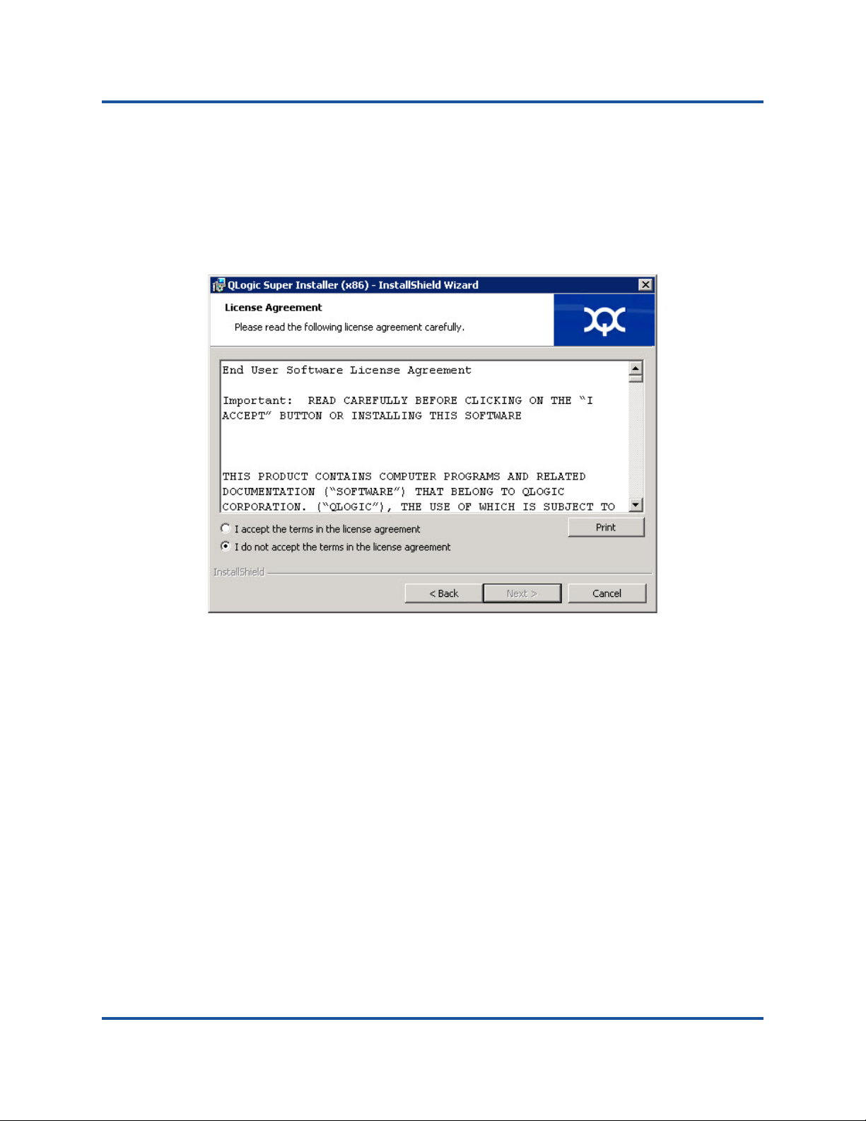
4. Complete the following in the wizard’s License Agreement window
(Step 3-3):
a. Read the QLogic End User Software License Agreement.
b. To continue, select I accept the terms in the license agreement.
c. Click Next.
Figure 3-3. QLogic InstallShield Wizard: License Agreement Window
20 BC0154503-00 C
Page 39

3–Installing Drivers
Windows Driver Software
5. Complete the wizard’s Setup Type window (Figure 3-4) as follows:
a. Select one of the following setup types:
b. To continue, click Next.
If you clicked Complete, proceed directly to Step 6b.
Click Complete to install all program features.
Click Custom to manually select the features to be installed.
Figure 3-4. InstallShield Wizard: Setup Type Window
21 BC0154503-00 C
Page 40

3–Installing Drivers
Windows Driver Software
6. If you selected Custom in Step 5, complete the Custom Setup window
(Figure 3-5) as follows:
a. Select the features to install. By default, all features are selected. To
b. Click Next to continue.
change a feature’s install setting, click the icon next to it, and then
select one of the following options:
This feature will be installed on the local hard drive—This
setting marks the feature for installation without affecting any of
its subfeatures.
This feature, and all subfeatures, will be installed on the
local hard drive—This setting marks the feature and all of its
subfeatures for installation.
This feature will not be available—This setting prevents the
feature from being installed.
Figure 3-5. InstallShield Wizard: Custom Setup Window
22 BC0154503-00 C
Page 41

3–Installing Drivers
Windows Driver Software
7. In the InstallShield Wizard’s Ready To Install window (Figure 3-6), click
Install. The InstallShield Wizard installs the QLogic Adapter drivers and
Management Software Installer.
Figure 3-6. InstallShield Wizard: Ready to Install the Program Window
8. When the installation is complete, the InstallShield Wizard Completed
window appears (Figure 3-7). Click Finish to dismiss the installer.
Figure 3-7. InstallShield Wizard: Completed Window
23 BC0154503-00 C
Page 42

3–Installing Drivers
NOTE
NOTE
Windows Driver Software
9. In the Dell Update Package window (Figure 3-8), “Complete” indicates
successful installation.
(Optional) To open the log file, click View Installation Log. The log file
To close the Update Package window, click CLOSE.
shows the progress of the DUP installation, any previous installed
versions, any error messages, and other information about the
installation.
Installation Options
To customize the Dell update package installation behavior, use the following
options.
To extract only the driver components to a directory:
/drivers=<path>
To install or update only the driver components:
/driveronly
Figure 3-8. Dell Update Package Window
This command requires the /s option.
This command requires the /s option.
24 BC0154503-00 C
Page 43

3–Installing Drivers
NOTE
Windows Driver Software
(Advanced) Use the /passthrough option to send all text following
/passthrough directly to the QLogic installation software of the Dell
update package. This mode suppresses any provided GUIs, but not
necessarily those of the QLogic software.
/passthrough
(Advanced) To return a coded description of this Dell update package's
supported features:
/capabilities
Examples
To update the system silently:
<DUP_file_name>.exe /s
This command requires the /s option.
To extract the update contents to the C:\mydir\ directory:
<DUP_file_name>.exe /s /e=C:\mydir
To extract the driver components to the C:\mydir\ directory:
<DUP_file_name>.exe /s /drivers=C:\mydir
To install only the driver components:
<DUP_file_name>.exe /s /driveronly
To change from the default log location to C:\my path with
spaces\log.txt:
<DUP_file_name>.exe /l="C:\my path with spaces\log.txt"
Removing the Windows Drivers
To remove the Windows drivers:
1. In Control Panel, click Programs, Programs and Features.
2. In the list of programs, select QLogic Driver and Management Super
Installer (x64), and then click Uninstall.
3. Follow the instructions.
25 BC0154503-00 C
Page 44

3–Installing Drivers
NOTE
Windows Driver Software
Managing Adapter Properties
To view or change the QL45212 Adapter properties
1. In Control Panel, click Device Manager.
2. Click the Advanced section of the chosen port.
Setting Power Management Options
You can set power management options to allow the operating system to turn off
the controller to save power or to allow the controller to wake up the computer. If
the device is busy doing something (servicing a call, for example), the operating
system will not shut down the device. The operating system attempts to shut down
every possible device only when the computer attempts to go into hibernation. To
have the controller stay on at all times, unselect the Allow the computer to turn
off the device to save power check box (Figure 3-9).
Figure 3-9. Power Management
The Power Management tab is available only for servers that support
power management. Do not select Allow the computer to turn off the
device to save power for any adapter that is a member of a team.
26 BC0154503-00 C
Page 45

3–Installing Drivers
VMware Driver Software
VMware Driver Software
This section describes the qedentv VMware ESXi driver for the QL45212 Adapter.
Installing VMware Drivers
VMware Driver Optional Parameters
VMware Driver Parameter Defaults
Removing the VMware Driver
Installing VMware Drivers
You can use the driver zip file to install a new driver or update an existing driver.
Be sure to install the entire driver set from the same driver zip file. Mixing drivers
from different zip files will cause problems.
To install the VMware driver
1. Go to www.vmware.com/support.html
the QL45212 Adapter.
2. Power up the ESX host, and then log into an account with administrator
authority.
3. Unzip the driver zip file, and then extract the .vib file.
4. Copy the .vib file to the ESX server. You can place the file anywhere that is
accessible to the ESX console shell.
Type the following command to use the Linux scp utility to copy a .vib file
from a local system into the /tmp directory on an ESX server with IP
address 10.10.10.10:
# scp qedentv-1.0.3.11-1OEM.550.0.0.1331820.x86_64.vib
root@10.10.10.10:/tmp
5. Place the host in maintenance mode by typing the following command:
# esxcli --maintenance-mode
6. You can install the .vib directly on an ESX server using the command line
interface, or with the VMware Update Manager (VUM). For information
about using the VUM, see the knowledge base article Updating an
ESXi/ESX host using VMware vCenter Update Manager 4.x and 5.x
(1019545).
and download the VMware driver for
To install the .vib file using the command line interface, type the following
command. Be sure to specify the full .vib file path.
# esxcli software vib install -v
/tmp/qedentv-1.0.3.11-1OEM.550.0.0.1331820.x86_64.vib
27 BC0154503-00 C
Page 46

3–Installing Drivers
VMware Driver Software
To upgrade an existing driver, follow the steps for a new installation, except
replace the command in Step 6 with the following:
# esxcli software vib update -v
/tmp/qedentv-1.0.3.11-1OEM.550.0.0.1331820.x86_64.vib
VMware Driver Optional Parameters
Table 3-4 describes the optional parameters that can be supplied as a command
line arguments to the esxcfg-module command.
Table 3-4. VMware Driver Optional Parameters
Parameter Description
hw_vlan The hw_lan parameter globally enables (1) or disables (0)
HW VLAN insertion and removal. Disable this parameter
when the upper layer needs to send or receive fully formed
packets. hw_vlan=1 is the default.
num_queues The num_queues parameter specifies the number of Tx/Rx
queue pairs. num_queues can be 1–11 or one of the following:
–1: Allow the driver to determine the optimal number of
queue pairs (default)
0: Use the default queue.
You can specify multiple values delimited by commas for mul-
tiport or multifunction configurations.
multi_rx_filters The multi_rx_filters parameter specifies the number of
Rx filters per Rx queue, excluding the default queue. mul-
ti_rx_filters can be 1–4 or one of the following values:
–1: Use the default number of Rx filters per queue.
0: Disable Rx filters.
disable_tpa Enables (0) or disables (1) the TPA (LRO) feature. dis-
able_tpa=0 is the default.
max_vfs Specifies the number of virtual functions (VFs) per physical
function (PF). max_vfs can be 0 (disable), or 8 or 16
(enable).
28 BC0154503-00 C
Page 47

3–Installing Drivers
VMware Driver Software
RSS The RSS parameter specifies the number of receive side scal-
debug The debug parameter specifies the level of data that the
Table 3-4. VMware Driver Optional Parameters (Continued)
Parameter Description
ing queues used by the host or virtual extensible LAN
(VxLAN) tunneled traffic for a PF. RSS can be 2, 3, or 4, or one
of the following values:
–1: Use the default number of queues.
0 or 1: Disable RSS queues.
You can specify multiple values delimited by commas for multiport or multifunction configurations.
driver records in the vmkernel log file. debug can have the
following values, shown in increasing amounts of data:
0x80000000: Notice level
0x40000000: Information level (includes the Notice level)
0x3FFFFFFF: Verbose level for all driver submodules
(includes the Information and Notice levels)
auto_fw_reset The auto_fw_reset parameter enables (1) or disables (0)
the driver automatic firmware recovery capability. When this
parameter is enabled, the driver attempts to recover from
events such as transmit timeouts, firmware asserts, and
adapter parity errors. The default is auto_fw_reset=1.
vxlan_filter_en The vxlan_filter_en parameter enables (1) or disables
(0) the VxLAN filtering based on the outer MAC, the inner
MAC, and the VxLAN network (VNI), directly matching traffic
to a specific queue. The default is vxlan_filter_en=1.
You can specify multiple values delimited by commas for multiport or multifunction configurations.
enable_vxlan_offld
The enable_vxlan_offld parameter enables (1) or disables (0) the VxLAN tunneled traffic checksum offload and
TCP segmentation offload (TSO) capability. The default is
enable_vxlan_offld=1. You can specify multiple values
delimited by commas for multiport or multifunction configurations.
29 BC0154503-00 C
Page 48

3–Installing Drivers
VMware Driver Software
VMware Driver Parameter Defaults
Table 3-5 lists the VMware driver parameter defaults.
Table 3-5. VMware Driver Parameter Defaults
Parameter Default
Speed Auto-negotiation with speed advertised
Flow Control Auto-negotiation with Rx and Tx advertised
MTU 1,500 (range 46–9,600)
Rx Ring Size 8,192 (range 128–8,192)
Tx Ring Size 8,192 (range 128–8,192)
MSI-X Enabled
Transmit Send Offload (TSO) Enabled
Large Receive Offload (LRO) Enabled
RSS Enabled (four Rx queues)
HW VLAN Enabled
Number of Queues Enabled (eight Rx/Tx queue pairs)
Wake on LAN (WoL) Disabled
Removing the VMware Driver
To remove the .vib file (qedentv), type the following command
#esxcli software vib remove --vibname qedentv
To remove the driver, type the following command:
#vmkload_mod -u qedentv
30 BC0154503-00 C
Page 49

4 Upgrading Firmware
This chapter provides information about the following topics:
Run by Double-Clicking
Run from the Command Line
Updating Dell DUP Using .BIN File
The firmware Dell update package is a Flash update utility only (it is not used for
adapter configuration). You run the firmware Dell update package by
double-clicking the executable file. Alternatively, the firmware Dell update
package can be run from the command line and supports a number of command
line options.
31 BC0154503-00 C
Page 50

4–Upgrading Firmware
Run by Double-Clicking
Run by Double-Clicking
To run the firmware Dell update package by double-clicking the executable file,
follow these instructions:
1. Double-click the icon representing the firmware Dell update package file.
The Dell update package splash screen appears, as shown in Figure 4-1.
Click Install to continue.
Figure 4-1. Dell Update Package Splash Screen
32 BC0154503-00 C
Page 51
4–Upgrading Firmware
Run by Double-Clicking
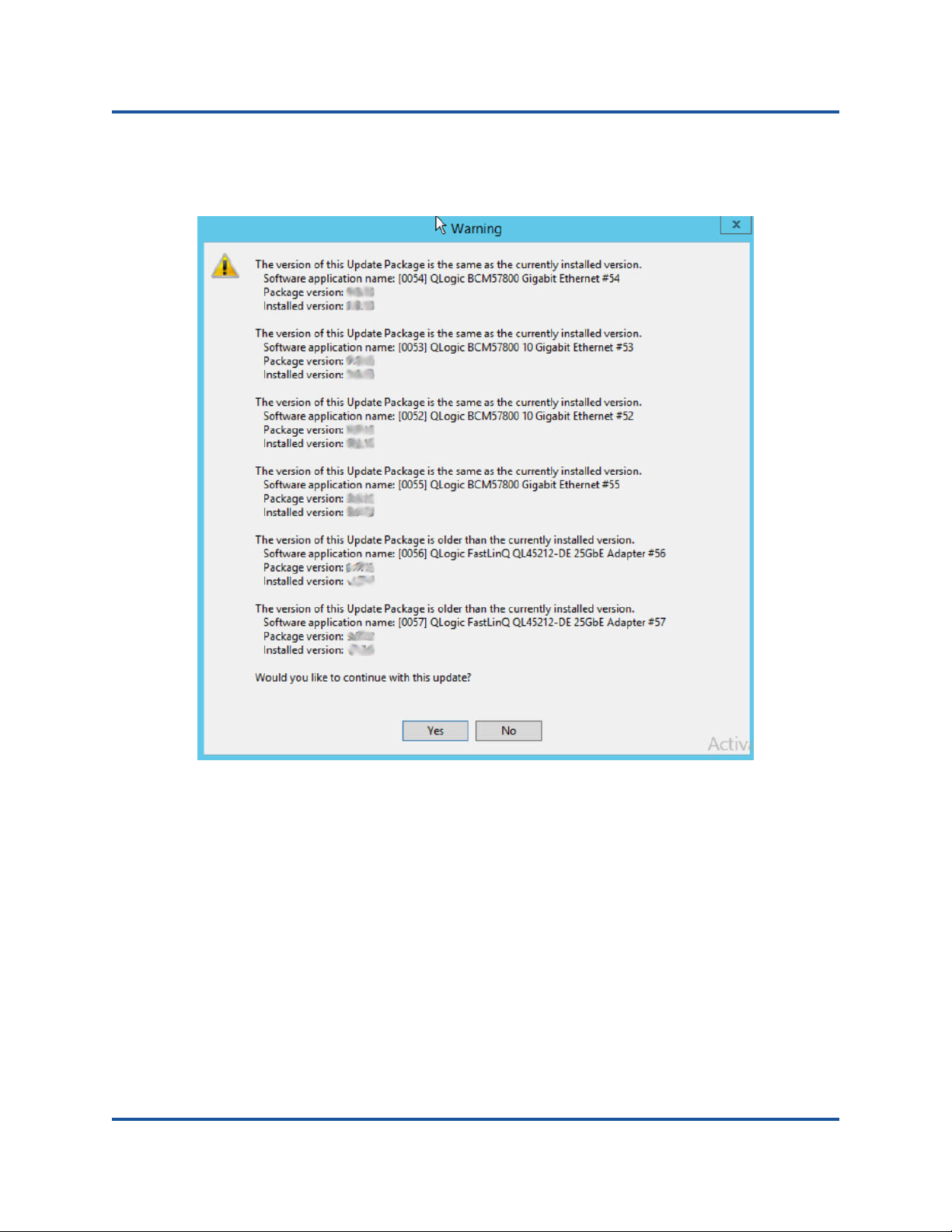
2. Follow the on-screen instructions. Click Yes to continue the installation, as
shown in Figure 4-2.
Figure 4-2. Continue Dell Update Package Installation
33 BC0154503-00 C
Page 52

4–Upgrading Firmware
Run by Double-Clicking
3. The installer indicates that it is loading the new firmware, as shown in
Figure 4-3.
Figure 4-3. Loading New Firmware
34 BC0154503-00 C
Page 53
4–Upgrading Firmware
Run by Double-Clicking
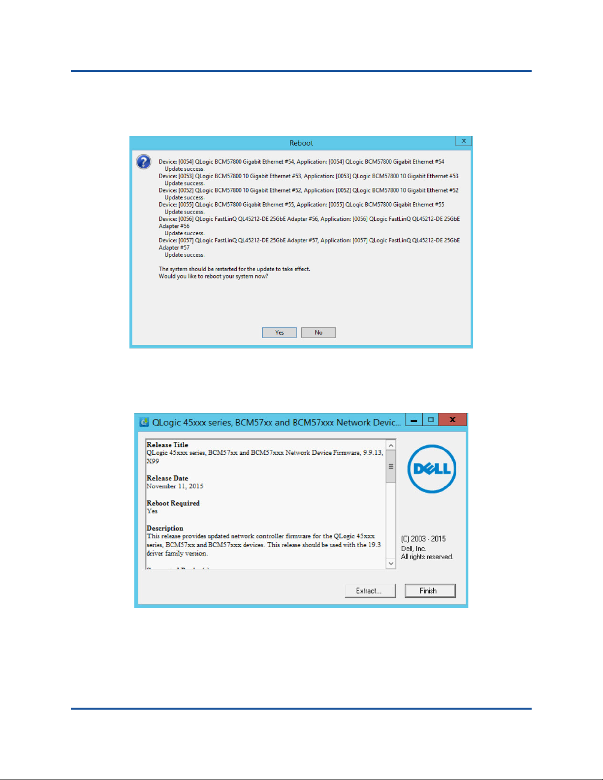
4. When complete, the installer indicates the result of the installation, as shown
in Figure 4-4. Click Yes to reboot.
Figure 4-4. Result of Installation
5. Click Finish to complete the installation, as shown in Figure 4-5.
Figure 4-5. Finish Installation
35 BC0154503-00 C
Page 54

4–Upgrading Firmware
Run from the Command Line
Run from the Command Line
Running the firmware Dell update package from the command line, with no
options specified, results in the same behavior as double-clicking the Dell update
package icon. Note that the actual file name of the Dell update package will vary.
C:\> Network_Firmware_2T12N_WN32_<version>_X16.EXE
The options shown in Figure 4-6 can be used to customize the Dell update
package installation.
Figure 4-6. Command Line Options
36 BC0154503-00 C
Page 55

4–Upgrading Firmware
Updating Dell DUP Using .BIN File
Updating Dell DUP Using .BIN File
Use the following procedure to update the Dell DUP using the .bin file:
1. Copy the Network_Firmware_NJCX1_LN_X.Y.Z.BIN file to SUT.
2. Change the file type into an executable file:
chmod 777 Network_Firmware_NJCX1_LN_X.Y.Z.BIN
3. Run ./Network_Firmware_NJCX1_LN_X.Y.Z.BIN to start the update
process.
4. Reboot the system after the firmware update.
The following is an example output from SUT during the DUP update.
./Network_Firmware_NJCX1_LN_08.07.26.BIN
Collecting inventory...
Running validation...
BCM57810 10 Gigabit Ethernet rev 10 (p2p1)
The version of this Update Package is the same as the currently
installed version.
Software application name: BCM57810 10 Gigabit Ethernet rev 10 (p2p1)
Package version: 08.07.26
Installed version: 08.07.26
BCM57810 10 Gigabit Ethernet rev 10 (p2p2)
The version of this Update Package is the same as the currently
installed version.
Software application name: BCM57810 10 Gigabit Ethernet rev 10 (p2p2)
Package version: 08.07.26
Installed version: 08.07.26
Continue? Y/N:Y
Y entered; update was forced by user
Executing update...
WARNING: DO NOT STOP THIS PROCESS OR INSTALL OTHER DELL PRODUCTS
WHILE UPDATE IS IN PROGRESS.
THESE ACTIONS MAY CAUSE YOUR SYSTEM TO BECOME UNSTABLE!
....................................................................
……………………………………………………………………………………………………………..
Device: BCM57810 10 Gigabit Ethernet rev 10 (p2p1)
Application: BCM57810 10 Gigabit Ethernet rev 10 (p2p1)
Update success.
Device: BCM57810 10 Gigabit Ethernet rev 10 (p2p2)
Application: BCM57810 10 Gigabit Ethernet rev 10 (p2p2)
Update success.
Would you like to reboot your system now?
Continue? Y/N:Y
37 BC0154503-00 C
Page 56

5 Preboot Adapter
Configuration
This chapter provides information about the following topics:
Getting Started
Displaying Firmware Image Properties
Device Level Configuration
NIC Configuration
Data Center Bridging Configuration
NIC Partitioning Configuration
38 BC0154503-00 C
Page 57
5–Preboot Adapter Configuration
NOTE
Getting Started
Getting Started
During the host boot process, you have the opportunity to pause and perform
adapter management tasks using the Human Infrastructure Interface (HII)
application. These tasks include the following:
Displaying Firmware Image Properties
Device Level Configuration
NIC Configuration
Data Center Bridging Configuration
NIC Partitioning Configuration
The HII screens in this chapter are representative and may not match the
screens that you see on your system.
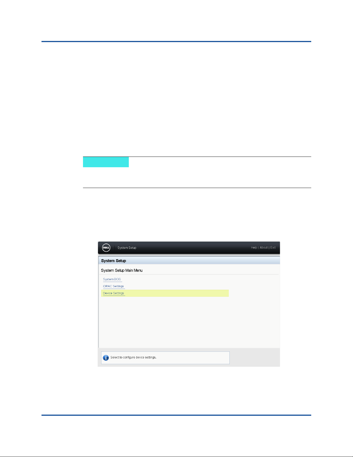
To start the HII application:
1. Open the System Setup page for your platform. For information about
launching the System Setup, consult the user guide for your platform.
2. In the System Setup page, select Device Settings, and then click Finish.
39 BC0154503-00 C
Page 58

5–Preboot Adapter Configuration
Getting Started
3. In the Device Settings page, select the QL45212 adapter port that you want
to configure.
4. The Main Configuration Page presents the adapter management options, as
shown in Figure 5-2.
Figure 5-1. Main Configuration Page
40 BC0154503-00 C
Page 59

5–Preboot Adapter Configuration
Displaying Firmware Image Properties
In addition to the management options, the Main Configuration Page presents the
adapter properties shown in Tab le 5 -1 .
Adapter Property Description
Device Name Factory-assigned device name
Chip Type ASIC version
PCI Device Id Unique vendor specific PCI device ID
PCI Address PCI device address in bus-device function format
Blink LEDs User-defined blink count for the port LED
Link Status External link status
MAC Address Manufacturer-assigned permanent device MAC address
Virtual MAC Address User-defined device MAC address
Table 5-1. Adapter Properties
Displaying Firmware Image Properties
To display firmware image properties, select Firmware Image Properties from
the Main Configuration Page (Figure 5-2). The Firmware Image Properties page
presents the following:
Family Firmware Version: multiboot image version, which comprises
several firmware images.
Controller BIOS Version: management firmware version
EFI Version: Unified extensible firmware interface (UEFI)/extensible
firmware interface (EFI) driver version
41 BC0154503-00 C
Page 60

5–Preboot Adapter Configuration
Device Level Configuration
Device Level Configuration
Device level configuration comprises enabling single root-I/O virtualization
(SR-IOV) and/or NIC partitioning, and enabling or disabling NPAReP. To perform
device level configuration, select Device Level Configuration in the Main
Configuration Page, and then click Finish. The Device Level Configuration page
is shown in Figure 5-2.
Figure 5-2. Device Level Configuration Page
To enable NIC partitioning (NPAR), single root input/output virtualization
(SR-IOV), or both:
1. Select Device Level Configuration in the Main Configuration Page
(Figure 5-1), and then click Finish.
2. In the Device Level Configuration page (Figure 5-2), click the Virtualization
Mode drop-down, and choose from the following options:
NPAR: Enables NPAR.
SRIOV: Enables SR-IOV (nonpartitioned virtualization)
NPAR+SRIOV: Enables NPAR with SR-IOV
None: Disables all virtualization
3. If NPAR is enabled (with or without SRIOV), and the system is capable of
alternate routing ID interpretation (ARI), choose to enable or disable
NPAReP mode:
42 BC0154503-00 C
Page 61

5–Preboot Adapter Configuration
NOTE
Device Level Configuration
Click Disabled to specify four partitions per port.
Click Enabled to specify eight partitions per port.
The QL45212 Adapter supports 8 virtual functions per port, with a total
of 16 virtual functions per adapter. If the NPAReP is enabled, the
QL45212 Adapter supports 16 virtual functions per partition. When
NPAReP is disabled, the last four virtual functions on each partition are
disabled and cannot be selected for configuration using the
QConvergeConsole GUI, the QCS CLI, or the vSphere Plug-in.
4. Click Back.
5. When prompted, click Yes to save the changes. Changes will take effect
after a system reset.
43 BC0154503-00 C
Page 62

5–Preboot Adapter Configuration
NIC Configuration
NIC Configuration
To configure the port link speed:
1. Select NIC Configuration in the Main Configuration Page (Figure 5-1), and
then click Finish.
2. In the NIC Configuration page, select from the link speed options listed in
Table 5-2. The link speed option you choose applies to both adapter ports.
The link speed and the forward error correction (FEC) must match that of the
connected switch or device port.
Option Description
Auto Negotiated Automatically negotiates the link parameters with the con-
Table 5-2. Link Speed Options
nected switch or device (default). Forward error correction
(FEC) is automatically enabled.
10Gbps Specifies the port link speed at 10Gbps. FEC is not sup-
ported.
25Gbps Specifies the port link speed at 25Gbps.
The FEC Mode option is available if the Link Speed is not set to Auto
Negotiated, and the link speed is set to 25G. Table 5-3 shows the FEC
Mode options.
Table 5-3. FEC Mode Options
Option Description
Disabled FEC is not supported
Fire Code If the link is configured to use Firecode FEC, the FEC
sublayer will operate similarly to Clause 74 FEC.
3. Click Back.
4. When prompted, click Yes to save the changes. Changes will take effect
after a system reset.
44 BC0154503-00 C
Page 63

5–Preboot Adapter Configuration
Data Center Bridging Configuration
Data Center Bridging Configuration
The data center bridging settings comprise the DCBX protocol and the remote
direct memory access (RDMA) over converged Ethernet (RoCE) priority.
To configure the data center bridging (DCB) settings:
1. Select Data Center Bridging (DCB) Settings in the Main Configuration
Page (Figure 5-1), and then click Finish.
2. In the Data Center Bridging (DCB) Settings page, click the DCBX Protocol
drop-down, and choose from the following options:
Disabled: Disables DCB
IEEE: IEEE protocol
CEE: Converged Enhanced Ethernet (CEE) protocol
Dynamic: Dynamically applies CEE or IEEE to match the attached link
partner
3. In the Data Center Bridging (DCB) Settings window, click the RoCE Priority
field, and then a type a value from 0–7.
4. Click Back.
5. When prompted, click Yes to save the changes. Changes will take effect
after a system reset.
45 BC0154503-00 C
Page 64

5–Preboot Adapter Configuration
NIC Partitioning Configuration
NIC Partitioning Configuration
To configure the maximum and minimum bandwidth allocations for each
partition:
1. Select NIC Partitioning Configuration in the Main Configuration Page
(Figure 5-1), and then click Finish.
2. In the NIC Partitioning Configuration page, select Global Bandwidth
Allocation.
3. In the Global Bandwidth Allocation page (Figure 5-3), click on each partition
minimum and maximum TX bandwidth field for which you want to allocate
bandwidth. There are four partitions per port if NPAReP mode is disabled;
eight partitions per port if NPAReP mode is enabled. NPAReP mode
requires that ARI be enabled in the BIOS for adapter’s PCI slot.
Figure 5-3. Global Bandwidth Allocation Page–NPAReP Mode Enabled
Partition N Minimum TX Bandwidth is the minimum transmit
bandwidth of the selected partition expressed as a percentage of the
maximum physical port link speed. Values can be 0–100. When DCBX
ETS mode is enabled, the per traffic class DCBX ETS minimum
bandwidth value overrides the per partition minimum TX bandwidth
value.The total of the minimum TX bandwidth values of all partitions on
a single port must equal 100 or be all zeros.
46 BC0154503-00 C
Page 65
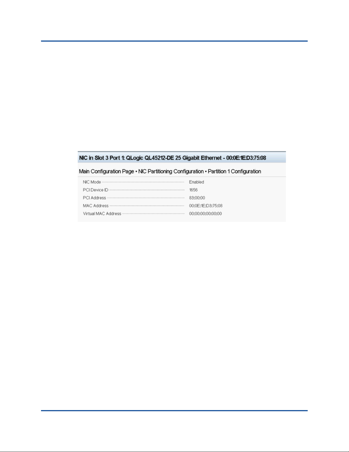
5–Preboot Adapter Configuration
NIC Partitioning Configuration
Partition N Maximum TX Bandwidth is the maximum transmit
bandwidth of the selected partition expressed as a percentage of the
maximum physical port link speed. Values can be 1–100. The per
partition maximum TX bandwidth value applies regardless of the
DCBX ETS mode setting. If the maximum TX bandwidth for a partition
is set to 0, the effective bandwidth is one percent.
Type a value in each selected field, and then click Back.
4. When prompted, click Yes to save the changes. Changes will take effect
after a system reset.
Figure 5-4 shows the partition configuration details.
Figure 5-4. Partition Configuration Details
47 BC0154503-00 C
Page 66

6 Configuring RoCE
This chapter describes RoCE (v1 and v2) configuration on the QL45212 Adapter,
the Ethernet switch, and the Windows or Linux host. This chapter describes the
following topics:
Supported Operating Systems and OFED
Planning
Preparing the Adapter
Preparing the Ethernet Switch
Configuring RoCE on the Adapter for Windows Server
Configuring RoCE on the Adapter for Linux
48 BC0154503-00 C
Page 67

6–Configuring RoCE
Supported Operating Systems and OFED
Supported Operating Systems and OFED
Table 6-1 shows the operating system support for RoCE v1/v2 and OFED:
Table 6-1. Operating System Support for RoCE v1/v2 and OFED
Planning
As you prepare to implement RoCE, consider the following limitations:
If you are using the in-box OFED, the operating system should be the same
For OFED applications (most often perftest applications), server and client
Operating System RoCE v1 RoCE v2 In-box OFED
Windows 2012 R2, 2016 Yes Ye s Yes No
RHEL 6.7, 6.8, 7.1, 7.2,
and 7.3
SLES 11 SP4, 12, 12
SP1, and 12 SP2 OS
CentOS 7.2 Yes No Yes No
on the server and client systems. Some of the applications may work
between different operating systems, but there is no guarantee. This is an
OFED limitation.
applications should use the same options and values. For example,
problems can arise if the operating system and the perftest application have
different OFED versions. To confirm the perftest OFED version, type the
following command:
Yes N o Ye s No
Yes No Yes No
Out-of-Box
OFED
# ib_send_bw --version
qedr and libqedr RPM packages are required for in-box OFED.
OFED/RDMA applications that depend on libibverbs also require the QLogic
RDMA user space library, libqedr. libqedr can be installed using libqedr RPM
or source packages
Mounting NFS over RDMA may take more time than normal on RHEL 7.0,
7.1, and SLES 12.
RoCE supports only little endian.
RoCE will not work over a VF in an SR-IOV environment.
RoCE is enabled by default for both V1 and V2.
49 BC0154503-00 C
Page 68

6–Configuring RoCE
Preparing the Adapter
Preparing the Adapter
The following steps describe how to enable DCBX, and specify the RoCE priority
using the HII management application. For information about the HII application,
see Chapter 5, Preboot Adapter Configuration.
1. In the Main Configuration Page, select Data Center Bridging (DCB)
Settings, and then click Finish.
2. In the Data Center Bridging (DCB) Settings window, click the DCBX
Protocol drop-down. The QL45212 Adapter supports both CEE and IEEE
protocols. This value should match the corresponding value on the DCB
switch. In this example, select CEE.
3. Click the RoCE Priority field, and type a priority value. This value should
match the corresponding value on the DCB switch. In this example, type 5.
4. Click Back.
5. When prompted, click Yes to save the changes. Changes will not take effect
unit after a system reset.
50 BC0154503-00 C
Page 69

6–Configuring RoCE
Preparing the Ethernet Switch
Preparing the Ethernet Switch
This section describes how to configure a Cisco® Nexus® 6000 Ethernet Switch
and a Dell Z9100 Ethernet switch for RoCE.
Cisco Nexus 6000 Ethernet Switch
Dell Z9100 Ethernet Switch
Cisco Nexus 6000 Ethernet Switch
Configuring the Cisco Nexus 6000 Ethernet Switch for RoCE comprises
configuring class maps, configuring policy maps, applying the policy, and
assigning a VLAN ID to the switch port.
1. Open a config terminal session.
Switch# config terminal
switch(config)#
2. Configure quality of service (QoS) class maps, setting the RoCE priority to
match the adapter (5).
switch(config)# class-map type qos class-roce
switch(config)# match cos 5
3. Configure queuing class maps.
switch(config)# class-map type queuing class-roce
switch(config)# match qos-group 3
4. Configure network QoS class maps.
switch(config)# class-map type network-qos class-ro
switch(config)# match qos-group 3
5. Configure QoS policy maps.
switch(config)# policy-map type qos roce
switch(config)# class type qos class-roc
switch(config)# set qos-group 3
6. Configure queuing policy maps to assign network bandwidth. In this
example, use a value of 50 percent.
switch(config)# policy-map type queuing roce
switch(config)# class type queuing class-roce
switch(config)# bandwidth percent 50
51 BC0154503-00 C
Page 70

6–Configuring RoCE
Preparing the Ethernet Switch
7. Configure network QoS policy maps to set priority flow control for no drop
traffic class.
switch(config)# policy-map type network-qos roce
switch(config)# class type network-qos class-roce
switch(config)# pause no-drop
8. Apply the new policy at the system level.
switch(config)# system qos
switch(config)# service-policy type qos input roce
switch(config)# service-policy type queuing output roce
switch(config)# service-policy type queuing input roce
switch(config)# service-policy type network-qos roce
9. Assign a VLAN ID to the switch port to match the VLAN ID assigned to the
adapter (5).
switch(config)# interface ethernet x/x
switch(config)# switchport mode trunk
switch(config)# switchport trunk allowed vlan 1,5
Dell Z9100 Ethernet Switch
Configuring the Dell Z9100 Ethernet Switch for RoCE comprises configuring a
DCB map for RoCE, configuring priority-based flow control (PFC) and enhanced
transmission selection (ETS), verifying the DCB map, applying the DCB map to
the port, verifying PFC and ETS on the port, specifying the DCB protocol, and
assigning a VLAN ID to the switch port.
1. Create a DCB map.
Dell# configure
Dell(conf)# dcb-map roce
Dell(conf-dcbmap-roce)#
2. Configure two ETS traffic classes in the DCB map with 50 percent
bandwidth assigned for RoCE (group 1).
Dell(conf-dcbmap-roce)# priority-group 0 bandwidth 50 pfc off
Dell(conf-dcbmap-roce)# priority-group 1 bandwidth 50 pfc on
3. Configure the PFC priority to match the adapter priority (5).
Dell(conf-dcbmap-roce)# priority-pgid 0 0 0 0 0 1 0 0
52 BC0154503-00 C
Page 71

6–Configuring RoCE
Preparing the Ethernet Switch
4. Verify the DCB map configuration. Priority group
Dell(conf-dcbmap-roce)# do show qos dcb-map roce
-----------------------
State :Complete
PfcMode :ON
--------------------
PG:0 TSA:ETS BW:40 PFC:OFF
Priorities:0 1 2 3 4 6 7
PG:1 TSA:ETS BW:60 PFC:ON
Priorities:5
5. Apply the DCB map to the port.
Dell(conf)# interface twentyFiveGigE 1/8/1
Dell(conf-if-tf-1/8/1)# dcb-map roce
6. Verify the ETS and PFC configuration on the port.
Dell(conf-if-tf-1/8/1)#
summary
Interface twentyFiveGigE 1/8/1
Max Supported TC is 4
Number of Traffic Classes is 8
Admin mode is on
Admin Parameters :
-----------------Admin is enabled
PG-grp Priority# BW-% BW-COMMITTED BW-PEAK TSA
% Rate(Mbps) Burst(KB) Rate(Mbps) Burst(KB)
-----------------------------------------------------------------------0 0,1,2,3,4,6,7 40 - - - - ETS
1 5 60 - - - - ETS
2 - - - - - -
3 - - - - - -
Dell(Conf)#
Interface twentyFiveGigE 1/5/1
Admin mode is on
Admin is enabled, Priority list is 5
Remote is enabled, Priority list is 5
Remote Willing Status is enabled
Local is enabled, Priority list is 5
Oper status is init
PFC DCBX Oper status is Up
State Machine Type is Feature
TLV Tx Status is enabled
PFC Link Delay 65535 pause quntams
Application Priority TLV Parameters :
------------------------------------- FCOE TLV Tx Status is disabled
ISCSI TLV Tx Status is enabled
Local FCOE PriorityMap is 0x0
Local ISCSI PriorityMap is 0x10
Remote ISCSI PriorityMap is 0x10
66 Input TLV pkts, 99 Output TLV pkts, 0 Error pkts, 0 Pause Tx pkts, 0 Pause Rx
pkts
66 Input Appln Priority TLV pkts, 99 Output Appln Priority TLV pkts, 0 Error Appln
Priority TLV Pkts
do show interfaces twentyFiveGigE 1/5/1 pfc detail
do show interfaces twentyFiveGigE 1/8/1 ets
53 BC0154503-00 C
Page 72

6–Configuring RoCE
Configuring RoCE on the Adapter for Windows Server
7. Configure the DCBX protocol (CEE in this example).
Dell(conf)# interface twentyFiveGigE 1/8/1
Dell(conf-if-tf-1/8/1)# protocol lldp
Dell(conf-if-tf-1/8/1-lldp)# dcbx version cee
8. Assign a VLAN ID to the switch port to match the VLAN ID assigned to the
adapter (5).
Dell(conf)# interface vlan 5
Dell(conf-if-vl-5)# tagged twentyFiveGigE 1/8/1
Configuring RoCE on the Adapter for Windows Server
Configuring RoCE on the adapter for Windows Server comprises enabling RoCE
on the adapter and verifying the Network Direct MTU size.
To configure RoCE on a Windows Server host:
1. Enable RoCE on the adapter.
a. Open the Windows Device Manager, and then open the QL45212
NDIS Miniport Properties.
b. Select Network Direct Functionality from the Property menu, and
then select Enabled in the Value field. Click OK.
54 BC0154503-00 C
Page 73
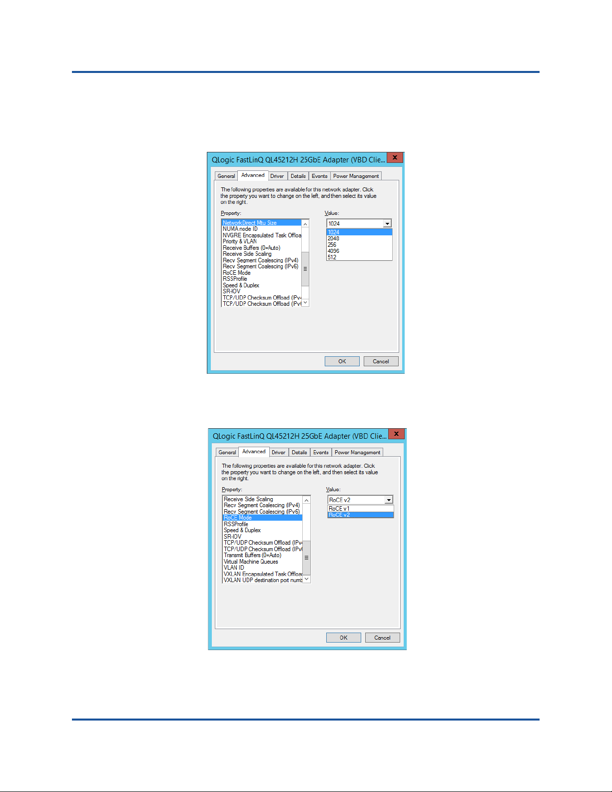
6–Configuring RoCE
Configuring RoCE on the Adapter for Windows Server
2. Select Network Direct Mtu Size from the Property menu. The network
direct MTU size must be less than the Ethernet jumbo packet size. In this
example, select 1024. Click OK.
3. Select RoCE Mode from the Property menu. In the Value: pull-down menu,
select RoCE v1 or RoCE v2. Click OK.
55 BC0154503-00 C
Page 74

6–Configuring RoCE
Configuring RoCE on the Adapter for Windows Server
4. Verify that RoCE is enabled on the adapter using Windows PowerShell®.
The Get-NetAdapterRdma command lists the adapters that support
RDMA—both ports are enabled.
PS C:\Users\Administrator> Get-NetAdapterRdma
Name InterfaceDescription Enabled
----- -------------------- -------
SLOT 4 3 Port 1 QLogic FastLinQ QL45212... True
SLOT 4 3 Port 2 QLogic FastLinQ QL45212... True
5. Verify that RoCE is enabled on the host operating system using PowerShell.
The Get-NetOffloadGlobalSetting command shows NetworkDirect is
enabled.
PS C:\Users\Administrators> Get-NetOffloadGlobalSetting
ReceiveSideScaling : Enabled
ReceiveSegmentCoalescing : Enabled
Chimney : Disabled
TaskOffload : Enabled
NetworkDirect : Enabled
NetworkDirectAcrossIPSubnets : Blocked
PacketCoalescingFilter : Disabled
6. Connect a server message block (SMB) drive, run RoCE traffic, and verify
the results.
a. Map an SMB drive, and then run RoCE traffic.
b. Launch Performance Monitor.
56 BC0154503-00 C
Page 75

6–Configuring RoCE
Configuring RoCE on the Adapter for Windows Server
c. Select <Local computer> under Select counters from computer:.
Select Add RDMA Activity, and then select <All instances> under
Instances of selected object;.
The following figure shows the presence of RDMA traffic.
57 BC0154503-00 C
Page 76

6–Configuring RoCE
Configuring RoCE on the Adapter for Windows Server
d. Verify the SMB connection using Windows PowerShell. Type the net
use and netstat -xan commands to show Share1 is mapped as
SMB share.
PS C:\Users\Administrator>
Status Local Remote Network
-------------------------------------------------------------
OK F: \\192.168.10.10\Share1 Microsoft Window
The command completed successfully.
PS C:\Users\Administrator>
Active NetworkDirect Connections, Listeners, SharedEndpoints
Mode IfIndex Type Local Address Foreign Address PID
Kernel 56 Connection 192.168.11.20.16159 192.168.11.10.445 0
Kernel 56 Connection 192.168.11.20.15903 192.168.11.10.445 0
Kernel 60 Connection 192.168.10.20.16159 192.168.10.10.445 0
Kernel 60 Connection 192.168.10.20.15903 192.168.10.10.445 0
Kernel 56 Listener [fe80:e11d:9ab5:a47d:4f0a%56]:445 NA 0
Kernel 56 Listener 192.168.11.20.445 NA 0
Kernel 60 Listener [fe80:71ea:bdd2:ae41:b95f%60]:445 NA 0
Kernel 60 Connection 192.168.10.20.445 NA 0
net use
netstat -xan
7. By default, Microsoft's SMB Direct establishes two RDMA connections per
port, which provides good performance, including line rate at higher block
size (for example, 64KB). To optimize performance, you can change the
number of RDMA connections per RDMA interface to four (or more).
To increase the number of RDMA connections to four (or more), type the
following command in PowerShell:
PS C:\Users\Administrator> Set-ItemProperty -Path `
"HKLM:\SYSTEM\CurrentControlSet\Services\LanmanWorkstation\Pa
rameters" ConnectionCountPerRdmaNetworkInterface -Type DWORD
-Value 4 –Force
58 BC0154503-00 C
Page 77

6–Configuring RoCE
NOTE
Configuring RoCE on the Adapter for Linux
Configuring RoCE on the Adapter for Linux
This section describes the RoCE configuration procedure for RHEL and SLES. It
also describes how to verify the RoCE configuration and provides some guidance
about using global IDs (GIDs) with VLAN interfaces.
RoCE v2 Configuring for Linux
To verify RoCE v2 functionality user needs to use RoCE v2 supported kernels. For
configuration, use the following procedure.
1. Check and make sure you are using one of the following supported kernels:
SLES 12 SP2 GA
RHEL 7.3 GA
2. Configure RoCEv2 using the following procedure:
You can configure RoCE v1, and v2 by using RoCE v2 supported
kernels. These kernels allow you to run RoCE traffic over same
subnet, as well as different subnets such as RoCE v2, and any
routable environment. Only few settings are required for RoCE v2, and
all other switch and adapter settings are common for RoCE v1 and v2.
a. Identify GID index for RoCE v2.
b. Configure routing address for server and client.
c. Enable L3 routing on the switch.
Identifying RoCE v2 GID Index or Address
To find RoCE v1 and v2 specific GIDs, use either sys or class parameters, or run
RoCE scripts from the 45000 Series FastLinQ source package. To check the
default RoCE GID Index, and address, run the ibv_devinfo command and
compare it with the sys or class parameters.
#ibv_devinfo -d qedr0 -v|grep GID
GID[ 0]: fe80:0000:0000:0000:020e:1eff:fec4:1b20
GID[ 1]: fe80:0000:0000:0000:020e:1eff:fec4:1b20
GID[ 2]: 0000:0000:0000:0000:0000:ffff:1e01:010a
GID[ 3]: 0000:0000:0000:0000:0000:ffff:1e01:010a
GID[ 4]: 3ffe:ffff:0000:0f21:0000:0000:0000:0004
GID[ 5]: 3ffe:ffff:0000:0f21:0000:0000:0000:0004
GID[ 6]: 0000:0000:0000:0000:0000:ffff:c0a8:6403
GID[ 7]: 0000:0000:0000:0000:0000:ffff:c0a8:6403
59 BC0154503-00 C
Page 78

6–Configuring RoCE
NOTE
Configuring RoCE on the Adapter for Linux
Verifying RoCE v1 or v2 GID Index, and Address from sys and class Parameters
Use one of the following options to verify RoCE v1 or v2 GID Index and address
from the sys and class parameters below:
Option 1
# cat /sys/class/infiniband/qedr0/ports/1/gid_attrs/types/0
IB/RoCE v1
# cat /sys/class/infiniband/qedr0/ports/1/gid_attrs/types/1
RoCE v2
# cat /sys/class/infiniband/qedr0/ports/1/gids/0
fe80:0000:0000:0000:020e:1eff:fec4:1b20
#cat /sys/class/infiniband/qedr0/ports/1/gids/1
fe80:0000:0000:0000:020e:1eff:fec4:1b20
Option 2
Use the scripts from the fastlinq-minor source package.
#/../fastlinq-minor-8.x.x.x/add-ons/roce/show_gids.sh
DEV PORT INDEX GID IPv4 VER DEV
--- ---- ----- --- ------------ --- ---
qedr0 1 0 fe80:0000:0000:0000:020e:1eff:fec4:1b20 v1 p4p1
qedr0 1 1 fe80:0000:0000:0000:020e:1eff:fec4:1b20 v2 p4p1
qedr0 1 2 0000:0000:0000:0000:0000:ffff:1e01:010a 30.1.1.10 v1 p4p1
qedr0 1 3 0000:0000:0000:0000:0000:ffff:1e01:010a 30.1.1.10 v2 p4p1
qedr0 1 4 3ffe:ffff:0000:0f21:0000:0000:0000:0004 v1 p4p1
qedr0 1 5 3ffe:ffff:0000:0f21:0000:0000:0000:0004 v2 p4p1
qedr0 1 6 0000:0000:0000:0000:0000:ffff:c0a8:6403 192.168.100.3 v1 p4p1.100
qedr0 1 7 0000:0000:0000:0000:0000:ffff:c0a8:6403 192.168.100.3 v2 p4p1.100
qedr1 1 0 fe80:0000:0000:0000:020e:1eff:fec4:1b21 v1 p4p2
qedr1 1 1 fe80:0000:0000:0000:020e:1eff:fec4:1b21 v2 p4p2
You must specify the GID index values for RoCE v1 or v2 based on
server or switch configuration (Pause/PFC). Use GID index for Link
local IPv6 address, or GID index for IPv4 address, or GID index for
IPv6 address. In order to use VLAN tagged frames for RoCE traffic,
you must specify GID index values that are derived from VLAN IPv4 or
IPv6 address.
60 BC0154503-00 C
Page 79

6–Configuring RoCE
NOTE
NOTE
Configuring RoCE on the Adapter for Linux
Verifying RoCE v1 or v2 Functionality Through perftest Applications
Use this section to verify RoCE v1 or v2 functionality through perftest applications.
In this example, the following Server IP and Client IP will be used:
Server IP: 192.168.100.3
Client IP: 192.168.100.4
Verifying RoCE v1
Run over the same subnet, and use RoCE v1 GID index.
Server# ib_send_bw -d qedr0 -F -x 0
Client# ib_send_bw -d qedr0 -F -x 0 192.168.100.3
Verifying RoCE v2
Run over the same subnet, and use the proper RoCE v2 GID index.
Server# ib_send_bw -d qedr0 -F -x 1
Client# ib_send_bw -d qedr0 -F -x 1 192.168.100.3
If you are running through switch PFC configuration, use VLAN GID’s
for RoCE v1 or v2 through the same subnet.
Verifying RoCE v2 through Different Subnets
Use the following procedure to verify RoCE v2 through different subnets.
You must first configure the route settings for the switch and servers. On the
adapter, set the RoCE priority, and DCBX mode using the HII or UEFI user
interface.
1. Set the route configuration for the Server and Client using DCBX-PFC
configuration.
System Settings
Server VLAN IP : 192.168.100.3 and Gateway :192.168.100.1
Client VLAN IP : 192.168.101.3 and Gateway :192.168.101.1
Server Configuration
#/sbin/ip link add link p4p1 name p4p1.100 type vlan id 100
#ifconfig p4p1.100 192.168.100.3/24 up
#ip route add 192.168.101.0/24 via 192.168.100.1 dev p4p1.100
61 BC0154503-00 C
Page 80

6–Configuring RoCE
Configuring RoCE on the Adapter for Linux
Client Configuration
#/sbin/ip link add link p4p1 name p4p1.101 type vlan id 101
#ifconfig p4p1.101 192.168.101.3/24 up
#ip route add 192.168.100.0/24 via 192.168.101.1 dev p4p1.101
2. Set the switch settings using the following procedure.
Use any flow control method (Pause,DCBX-CEE/DCBX-IEEE), and enable
IP routing for RoCE v2. See “Preparing the Ethernet Switch” on page 51 for
RoCE v2 configuration, or refer to the vendor switch documents.
If you are using PFC Configuration and L3 routing, run RoCE v2 traffic over
VLAN using a different subnet, and use RoCE v2 VLAN GID index.
Server# ib_send_bw -d qedr0 -F -x 5
Client# ib_send_bw -d qedr0 -F -x 5 192.168.100.3
Server:
62 BC0154503-00 C
Page 81

6–Configuring RoCE
Configuring RoCE on the Adapter for Linux
Client:
Configuring RoCE v1 or v2 Settings for RDMA_CM Applications
Use the following scripts from fastlinq-minor source package:
#./show_rdma_cm_roce_ver.sh
qedr0 is configured to IB/RoCE v1
qedr1 is configured to IB/RoCE v1
# ./config_rdma_cm_roce_ver.sh v2
configured rdma_cm for qedr0 to RoCE v2
configured rdma_cm for qedr1 to RoCE v2
Server:
63 BC0154503-00 C
Page 82
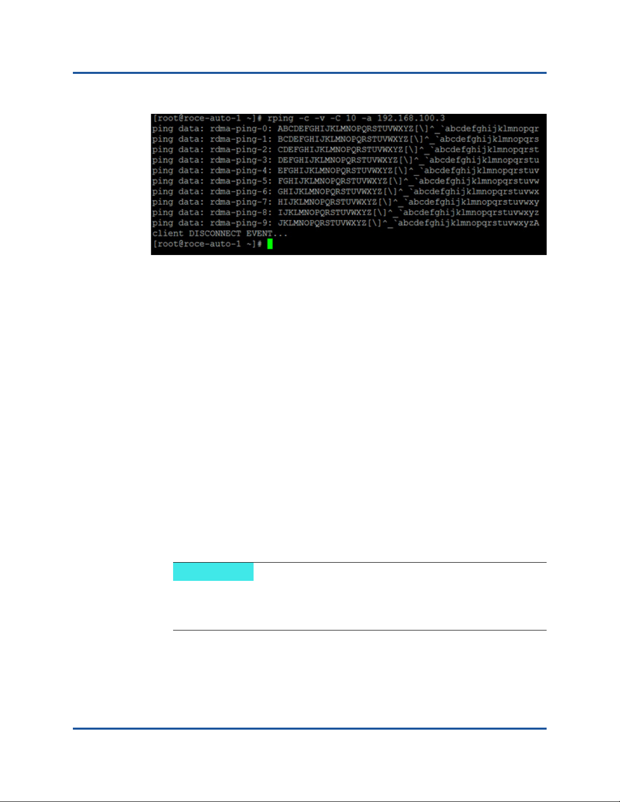
6–Configuring RoCE
NOTE
Configuring RoCE on the Adapter for Linux
Client:
RoCE Configuration for RHEL
To configure RoCE on the adapter, the Open Fabrics Enterprise Distribution
(OFED) must be installed and configured on the RHEL host. To prepare in-box
OFED for RHEL:
1. While installing or upgrading the operating system, select the Infiniband and
OFED support packages.
2. Install the following RPMs from RHEL ISO image:
libibverbs-devel-x.x.x.x86_64.rpm
(required for libqedr library)
perftest-x.x.x.x86_64.rpm
(required for IB bandwidth and latency applications)
or, using Yum, install the in-box OFED:
yum groupinstall "Infiniband Support"
yum install perftest
yum install tcl tcl-devel tk zlib-devel libibverbs
libibverbs-devel
During installation, if you already selected the previously mentioned
packages, you need not reinstall them. The in-box OFED and support
packages may vary depending on the operating system version.
3. Install the new Linux drivers, as described in “Installing the Linux Drivers
with RoCE” on page 16.
64 BC0154503-00 C
Page 83

6–Configuring RoCE
Configuring RoCE on the Adapter for Linux
RoCE Configuration for SLES
To configure RoCE on the adapter for an SLES host, OFED must be installed and
configured on the SLES host. To install in-box OFED for SLES Linux:
1. While installing or upgrading the operating system, select the Infiniband
support packages.
2. Install the following RPMs from the corresponding SLES SDK kit image:
libibverbs-devel-x.x.x.x86_64.rpm
(required for libqedr installation)
perftest-x.x.x.x86_64.rpm
(required for bandwidth and latency applications)
3. Install the Linux drivers, as described in “Installing the Linux Drivers with
RoCE” on page 16.
Verifying the RoCE Configuration on Linux
After installing OFED, installing the Linux driver, and loading the RoCE drivers,
verify that the RoCE devices were detected on all Linux operating systems:
1. Stop firewall tables using service/systemctl commands.
2. Verify that the RDMA services has started using the
service rdma status command. If RDMA has not started, type the
following command:
# service rdma start
If RDMA does not start, type either of the following alternative commands:
# /etc/init.d/rdma start
or
# systemctl start rdma.service
3. Verify that the RoCE devices were detected by examining the dmesg logs.
# dmesg|grep qedr
[87910.988411] qedr: discovered and registered 2 RoCE funcs
4. Verify that all of the modules have been loaded. For example:
# lsmod|grep qedr
qedr 89871 0
qede 96670 1 qedr
qed 2075255 2 qede,qedr
ib_core 88311 16 qedr, rdma_cm, ib_cm,
ib_sa,iw_cm,xprtrdma,ib_mad,ib_srp,
65 BC0154503-00 C
Page 84

6–Configuring RoCE
Configuring RoCE on the Adapter for Linux
ib_ucm,ib_iser,ib_srpt,ib_umad,
ib_uverbs,rdma_ucm,ib_ipoib,ib_isert
5. Configure the IP address and enable the port using a configuration method,
such as ifconfig:
# ifconfig ethX 192.168.10.10/24 up
6. Type the ibv_devinfo command. For each PCI function, you should see a
separate hca_id, as shown in the following example:
root@captain:~# ibv_devinfo
hca_id: qedr0
transport: InfiniBand (0)
fw_ver: 8.3.9.0
node_guid: 020e:1eff:fe50:c7c0
sys_image_guid: 020e:1eff:fe50:c7c0
vendor_id: 0x1077
vendor_part_id: 5684
hw_ver: 0x0
phys_port_cnt: 1
port: 1
state: PORT_ACTIVE (1)
max_mtu: 4096 (5)
active_mtu: 1024 (3)
sm_lid: 0
port_lid: 0
port_lmc: 0x00
link_layer: Ethernet
7. Verify the L2 and RoCE connectivity between all servers: one server acts as
a server, another acts as a client.
Verify the L2 connection using a simple ping command.
Verify the RoCE connection by performing an RDMA ping:
On the server, type the following command:
ibv_rc_pingpong -d <ib-dev> -g 0
On the client, type the following command:
ibv_rc_pingpong -d <ib-dev> -g 0 <server L2 IP address>
66 BC0154503-00 C
Page 85

6–Configuring RoCE
Configuring RoCE on the Adapter for Linux
The following are examples of successful ping pong tests on the server and
the client:
Server:
root@captain:~# ibv_rc_pingpong -d qedr0 -g 0
local address: LID 0x0000, QPN 0xff0000, PSN 0xb3e07e, GID
fe80::20e:1eff:fe50:c7c0
remote address: LID 0x0000, QPN 0xff0000, PSN 0x934d28, GID
fe80::20e:1eff:fe50:c570
8192000 bytes in 0.05 seconds = 1436.97 Mbit/sec
1000 iters in 0.05 seconds = 45.61 usec/iter
Client:
root@lambodar:~# ibv_rc_pingpong -d qedr0 -g 0 192.168.10.165
local address: LID 0x0000, QPN 0xff0000, PSN 0x934d28, GID
fe80::20e:1eff:fe50:c570
remote address: LID 0x0000, QPN 0xff0000, PSN 0xb3e07e, GID
fe80::20e:1eff:fe50:c7c0
8192000 bytes in 0.02 seconds = 4211.28 Mbit/sec
1000 iters in 0.02 seconds = 15.56 usec/iter
To display RoCE statistics, type the following commands, where X is the
device number:
> mount -t debugfs nodev /sys/kernel/debug
> cat /sys/kernel/debug/qedr/qedrX/stats
67 BC0154503-00 C
Page 86

6–Configuring RoCE
NOTE
Configuring RoCE on the Adapter for Linux
VLAN Interfaces and GID Index Values
If you are using VLAN interfaces on both server and client, then configure the
same VLAN ID on the switch. If you are running traffic through a switch, the
Infiniband applications must use the correct GID value, which is based on the
VLAN ID and VLAN IP address.
Based on the following results, the GID value (-x 4 / -x 5) should be used for any
perftest applications.
# ibv_devinfo -d qedr0 -v|grep GID
GID[ 0]:
fe80:0000:0000:0000:020e:1eff:fe50:c5b0
GID[ 1]:
0000:0000:0000:0000:0000:ffff:c0a8:0103
GID[ 2]:
2001:0db1:0000:0000:020e:1eff:fe50:c5b0
GID[ 3]:
2001:0db2:0000:0000:020e:1eff:fe50:c5b0
GID[ 4]:
0000:0000:0000:0000:0000:ffff:c0a8:0b03 IP address for VLAN interface
GID[ 5]:
fe80:0000:0000:0000:020e:1e00:0350:c5b0 VLAN ID 3
The default GID value is zero (0) for back-to-back/Pause settings. For
server/switch configurations, you must identify the proper GID Value. If you
are using a switch, refer to the corresponding switch configuration
documents for the proper settings.
68 BC0154503-00 C
Page 87

7 iSCSI Extensions for RDMA
This chapter describes the procedure for configuring iSCSI Extensions for RDMA
(iSER) for RHEL and SLES.
Configuring iSER for RHEL
Configuring iSER for SLES12 Linux
Optimizing Linux Performance
As you prepare to configure iSER, consider the following:
iSER is supported only in INBOX OFED for following operating systems:
RHEL 7.1, 7.2
SLES 12, and 12 SP1
CentOS 7.2
Out-of-box OFED does not support iSER target configuration and no ib_isert
module is available for latest out-of-box OFED versions.
After logging into the targets or while running I/O traffic, unloading the Linux
RoCE qedr driver may crash the system.
While running I/O, performing interface down/up tests or performing cable
pull-tests can cause driver or iSER module errors that may crash the
system. If this happens, reboot the system.
69 BC0154503-00 C
Page 88

7–iSCSI Extensions for RDMA
Configuring iSER for RHEL
Configuring iSER for RHEL
To configure iSER for RHEL:
1. Configure in-box OFED, as described “RoCE Configuration for RHEL” on
page 64. Out-of-box OFEDs are not supported for iSER because the ib_isert
module is not available in the out-of-box OFED-3.18/3.81-1 GA versions.
The inbox ib_isert module does not work with any out-of-box OFED
versions.
2. Unload any existing FastLinQ drivers, as described in “Removing Linux
Drivers in a RoCE Environment” on page 13.
3. Install the latest FastLinQ driver and libqedr packages, as described in
“Installing the Linux Drivers with RoCE” on page 16.
4. Load the RDMA services.
systemctl start rdma
modprobe qedr
modprobe ib_iser
modprobe ib_isert
5. Verify all RDMA and iSER modules loaded on the initiator and target devices
using the lsmod | grep qed and lsmod | grep iser commands.
6. Verify that there are separate hca_id instances by typing the ibv_devinfo
command, as described in Step 6 on page 66.
7. Check the RDMA connection on the initiator device and the target device.
Initiator device:
rping -s -C 10 -v
Target device:
rping -c -a 192.168.100.99 -C 10 -v
70 BC0154503-00 C
Page 89

7–iSCSI Extensions for RDMA
Configuring iSER for RHEL
The following figure shows an example of a successful RDMA ping.
8. You can use a Linux TCM-LIO target with which to test iSER. The setup is
the same for any iSCSI target, except you type command
enable_iser Boolean=true on the applicable portals. The portal
instances are identified as "iser" as shown in the following figure:
9. Install Linux iSCSI Initiator Utilities using the
yum install iscsi-initiator-utils commands.
a. Discover the iSER target by typing command such as the following:
iscsiadm -m discovery -t st -p 192.168.100.99:3260
b. Change the transport mode to iSER by typing command such as the
following:
iscsiadm -m node -T iqn.2015-06.test.target1 -o update -n
iface.transport_name -v iser
71 BC0154503-00 C
Page 90
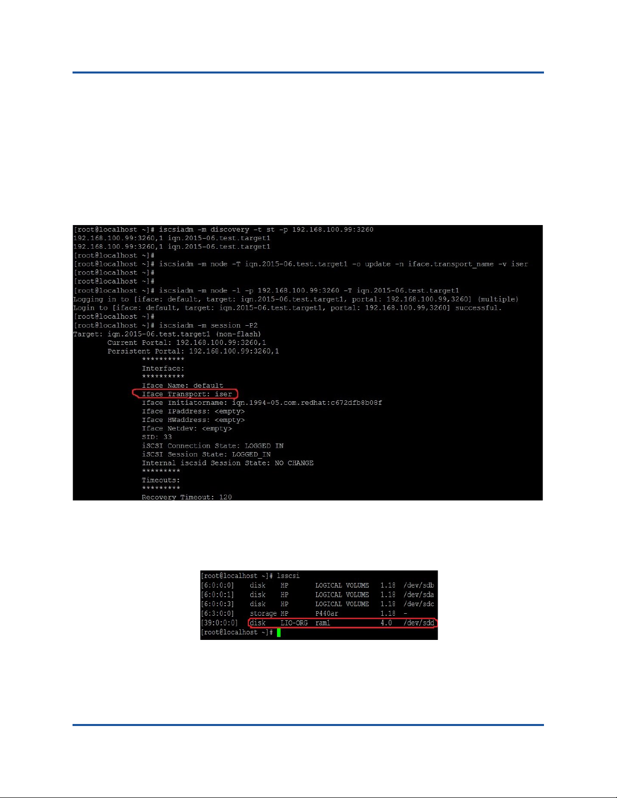
7–iSCSI Extensions for RDMA
Configuring iSER for RHEL
c. Connect to or login to the iSER target by typing a command such as
the following:
iscsiadm -m node -l -p 192.168.100.99:3260 -T
iqn.2015-06.test.target1
d. Confirm that the Iface Transport is iser in the target connection, as
shown in the following figure. Type a command such as the following:
iscsiadm -m session -P2
e. Check for a new iSCSI device, as shown in the following figure. Type
command such as the following:
lsscsi
72 BC0154503-00 C
Page 91

7–iSCSI Extensions for RDMA
NOTE
Configuring iSER for SLES12 Linux
Configuring iSER for SLES12 Linux
The TargetCLI is not in-box on SLES12, therefore you must do the following:
1. To install TargetCLI, copy and install the following RPMs from ISO image
(x86_64 and noarch location).
lio-utils-4.1-14.6.x86_64.rpm
python-configobj-4.7.2-18.10.noarch.rpm
python-PrettyTable-0.7.2-8.5.noarch.rpm
python-configshell-1.5-1.44.noarch.rpm
python-pyparsing-2.0.1-4.10.noarch.rpm
python-netifaces-0.8-6.55.x86_64.rpm
python-rtslib-2.2-6.6.noarch.rpm
python-urwid-1.1.1-6.144.x86_64.rpm
targetcli-2.1-3.8.x86_64.rpm
2. Before starting the TargetCLI, load all RoCE device drivers and iSER
modules.
# modprobe qed
# modprobe qede
# modprobe qedr
# modprobe ib_iser (Initiator)
# modprobe ib_isert (Target)
3. Configure NIC interfaces and run L2 and RoCE traffic before configuring
iSER targets, as described in Step 7 on page 66.
4. Start the TargetCLI utility, and configure your targets on the iSER target
system.
TargetCLI versions are different in RHEL and SLES. Be sure to use the
proper backstores to configure your targets. RHEL uses ramdisk;
SLES uses rd_mcp.
73 BC0154503-00 C
Page 92

7–iSCSI Extensions for RDMA
Optimizing Linux Performance
Optimizing Linux Performance
Consider the Linux performance enhancements.
Set CPUs to Maximum Performance Mode
Set the CPU scaling governor to performance by using the following script to set
all CPUs to maximum Performance mode
for CPUFREQ in
/sys/devices/system/cpu/cpu*/cpufreq/scaling_governor; do [ -f
$CPUFREQ ] || continue; echo -n performance > $CPUFREQ; done
Verify that all CPU cores were set to maximum performance mode by typing the
following command:
cat /sys/devices/system/cpu/cpu*/cpufreq/scaling_governor
Set Kernel sysctl Settings
Set the kernel sysctl settings as follows:
sysctl -w net.ipv4.tcp_mem="4194304 4194304 4194304"
sysctl -w net.ipv4.tcp_wmem="4096 65536 4194304"
sysctl -w net.ipv4.tcp_rmem="4096 87380 4194304"
sysctl -w net.core.wmem_max=4194304
sysctl -w net.core.rmem_max=4194304
sysctl -w net.core.wmem_default=4194304
sysctl -w net.core.rmem_default=4194304
sysctl -w net.core.netdev_max_backlog=250000
sysctl -w net.ipv4.tcp_timestamps=0
sysctl -w net.ipv4.tcp_sack=1
sysctl -w net.ipv4.tcp_low_latency=1
sysctl -w net.ipv4.tcp_adv_win_scale=1
echo 0 > /proc/sys/vm/nr_hugepages
74 BC0154503-00 C
Page 93

7–iSCSI Extensions for RDMA
Optimizing Linux Performance
IRQ Affinity Settings
This example sets CPU core 0, 1, 2 and 3 to IRQ XX, YY, ZZ and XYZ
respectively. This will need to be done for each IRQ assigned to a port (default is
eight queues per port)
systemctl disable irqbalance
systemctl stop irqbalance
cat /proc/interrupts | grep qedr Shows IRQ assigned to each port queue
echo 1 > /proc/irq/XX/smp_affinity_list
echo 2 > /proc/irq/YY/smp_affinity_list
echo 4 > /proc/irq/ZZ/smp_affinity_list
echo 8 > /proc/irq/XYZ/smp_affinity_list
Block Device Staging
Set the block device staging settings for each iSCSI device/target:
echo noop > /sys/block/sdd/queue/scheduler
echo 2 > /sys/block/sdd/queue/nomerges
echo 0 > /sys/block/sdd/queue/add_random
echo 1 > /sys/block/sdd/queue/rq_affinity
75 BC0154503-00 C
Page 94

8 Troubleshooting
This chapter provides information about the following topics:
Troubleshooting Checklist
Verifying that Current Drivers are Loaded
Testing Network Connectivity
Microsoft Virtualization with Hyper-V
Linux
Miscellaneous
Collecting Debug Data
76 BC0154503-00 C
Page 95

8–Troubleshooting
CAUTION
Troubleshooting Checklist
Troubleshooting Checklist
Before you open the server cabinet to add or remove the adapter, review
“Safety Precautions” on page 7.
The following checklist provides recommended actions to resolve problems that
may arise while installing the QL45212 Adapter or running it in your system.
Inspect all cables and connections. Verify that the cable connections at the
network adapter and the switch are attached properly.
Verify the adapter installation by reviewing “Installing the Adapter” on
page 8. Verify that the adapter is properly seated in the slot. Check for
specific hardware problems, such as obvious damage to board components
or the PCI edge connector.
Verify the configuration settings and change them if they are in conflict with
another device.
Verify that your server is using the latest BIOS.
Try inserting the adapter in another slot. If the new position works, the
original slot in your system may be defective.
Replace the failed adapter with one that is known to work properly. If the
second adapter works in the slot where the first one failed, the original
adapter is probably defective.
Install the adapter in another functioning system, and then run the tests
again. If the adapter passes the tests in the new system, the original system
may be defective.
Remove all other adapters from the system, and then run the tests again. If
the adapter passes the tests, the other adapters may be causing contention.
77 BC0154503-00 C
Page 96

8–Troubleshooting
Verifying that Current Drivers are Loaded
Verifying that Current Drivers are Loaded
Windows
See the Device Manager to view vital information about the adapter, link status,
and network connectivity.
Linux
To verify that the qed.ko driver is loaded properly, run:
# lsmod | grep -i <module name>
If the driver is loaded, the output of this command shows the size of the driver in
bytes. The following example shows the drivers loaded for the qed module:
# lsmod | grep -i qed
qed 199238 1
qede 1417947 0
If you reboot after loading a new driver, you can use the following command to
verify that the currently loaded driver is the correct version:
modinfo qede
Or, you can use the following command:
[root@test1]# ethtool -i eth2
driver: qede
version: 8.4.7.0
firmware-version: mfw 8.4.7.0 storm 8.4.7.0
bus-info: 0000:04:00.2
If you loaded a new driver, but have not yet booted, the modinfo command will
not show the updated driver information. Instead, type the following dmesg
command to view the logs. In this example, the last entry identifies the driver that
will be active upon reboot.
# dmesg | grep -i "QLogic" | grep -i "qede"
[ 10.097526] QLogic FastLinQ 4xxxx Ethernet Driver qede x.x.x.x
[ 23.093526] QLogic FastLinQ 4xxxx Ethernet Driver qede x.x.x.x
[ 34.975396] QLogic FastLinQ 4xxxx Ethernet Driver qede x.x.x.x
[ 34.975896] QLogic FastLinQ 4xxxx Ethernet Driver qede x.x.x.x
[ 3334.975896] QLogic FastLinQ 4xxxx Ethernet Driver qede x.x.x.x
78 BC0154503-00 C
Page 97

8–Troubleshooting
NOTE
Testing Network Connectivity
Testing Network Connectivity
When using forced link speeds, verify that both the adapter and the switch
are forced to the same speed.
Network Connectivity Testing for Windows
Network connectivity can be tested using the ping command to determine if the
network connection is working.
1. Click Start, and then click Run.
2. Type cmd in the Open box, and then click OK.
3. Type ipconfig /all to view the network connection to be tested.
4. Type ping <ip_address>, and then press ENTER.
The ping statistics that are displayed indicate whether the network connection is
working or not.
The adapter link speed can be forced to 10Gbps or 25Gbps using the following
methods:
QConvergeConsole
Network Adapter, Advanced Properties—Speed & Duplex settings
QCS CLI:
qcscli –t ndis –f bdf –i <bus:device.function number of
port> “cfg advanced \”speed \”&\” duplex\”=\”10 gbps
full duplex\””
Windows
Network Adapter, Advanced Properties—Speed & Duplex settings
Windows PowerShell
Set-NetAdapterAdvancedProperty –Name “<port name>”
–DisplayName “Speed & Duplex” –DisplayValue “10 Gbps
Full Duplex
®
Device Manager:
®
GUI:
®
:
79 BC0154503-00 C
Page 98

8–Troubleshooting
Microsoft Virtualization with Hyper-V
Network Connectivity Testing for Linux
To verify that the Ethernet interface is up and running, run ifconfig to check the
status of the Ethernet interface. Use netstat -i to check the statistics on the
Ethernet interface.
Ping an IP host on the network to verify that the connection has been
established.From the command line, type ping <ip_address>, and then press
ENTER. The ping statistics that are displayed indicate whether or not the network
connection is working.
The adapter link speed can be forced to 10Gbps or 25Gbps using the operating
systems GUI tool, or the ethtool command, ethtool –s ethX speed SSSS.
Microsoft Virtualization with Hyper-V
Microsoft Virtualization is a hypervisor virtualization system for Windows Server
2012 R2. For more information on Hyper-V, see
https://technet.microsoft.com/en-us/library/Dn282278.aspx
.
Linux
Problem: QL45212 devices with SFP+ Flow Control default to Off rather than
Rx/Tx Enable.
Solution: The Flow Control default setting for revision 1.6.x and newer has been
changed to Rx Off and Tx Off because SFP+ devices do not support
auto-negotiation for Flow Control.
Problem: Errors appear when compiling driver source code.
Solution: Some installations of Linux distributions do not install the development
tools by default. Ensure the development tools for the Linux distribution you are
using are installed before compiling driver source code.
Miscellaneous
Problem: The QL45212 Adapter has shut down, and an error message appears
indicating that the fan on the adapter has failed.
Solution: The QL45212 Adapter shut down to prevent permanent damage.
Contact QLogic Technical Support for assistance.
80 BC0154503-00 C
Page 99

8–Troubleshooting
Collecting Debug Data
Collecting Debug Data
Use the information in table x.x to collect debug data.
Table 8-1. Collecting Debug Data Commands
Debug Data Description
demesg-T Kernel logs
ethtool-d Register dump.
sys_info.sh System information. This is available in the driver bundle.
81 BC0154503-00 C
Page 100

A Adapter LEDS
Network link and activity status are indicated by the Link and Activity LEDs located
adjacent to the port connector, as described in Table A-1.
Table A-1. Port LED Indications
Port LED LED Appearance Network State
Link LED Off No link (cable discon-
Continuously illuminated Link
Activity LED Off No network activity
Blinking Network activity
nected)
82 BC0154503-00 C
 Loading...