

Page 1

[ Quick Start Guide ]
QUICK START GUIDE
INFINIBAND SWITCH INSTALLATION
QLogic 12000 Series
z
Page 2

Purchasers of OEM products should consult with the OEM for support.
Support Headquarters QLogic Corporation
4601 Dean Lakes Blvd
Shakopee, MN 55379
QLogic Web Site www.qlogic.com
Technical Support Web Site support.qlogic.com
Technical Support Email support@qlogic.com
Technical Training Email tech.training@qlogic.com
Support phone numbers are available in the
support.qlogic.com
Contact Support area of the QLogic support
website:
Page 3

QLogic 12000
Quick Start Guide
Installation Instructions
This guide describes the steps to install and activate a 12000-series InfiniBand switch. For detailed instructions, refer
to the QLogic 12000 Hardware Installation Guide.
NOTE: For the 12005-PT16, please consult your modular blade enclosure documentation for detailed installation
instructions.
Step 1. Check the Packing List
1. Verify all ordered equipment has been received. The 12000 switches ship with all components
pre-installed. The following table lists the maximum
switch:
Table 1. 12000-Series Components
Component 12200 12300 12400-6/12 12800-040 12800-120 12800-180 12800-360
configuration of installed components for each
Fans N/A N/A N/A 4 Intake 5 Intake
3 Exhaust
Power
Supplies or
Blank Fillers
IB Leaf
Modules/
Blanks
Spine
Modules/
Blanks
Management
Modules/
Blanks
I/O Modules N/A N/A 1/2 N/A N/A N/A N/A
Hardware
Installation
kit (mounting
rails, etc.)
DB-9 to
RJ-11
adapter
N/A 2
Power/
Fan units
N/A N/A N/A 4 12 18 36
N/A N/A N/A 1 3 5 9
N/A N/A N/A 2 2 2 2
1 1 1 1 1 1 1
N/A 1 1 2 2 2 2
2
Power/
Fan units
4 4 6 12
5 Intake
3 Exhaust
10 Intake
10 Exhaust
3
Page 4

Table 1. 12000-Series Components
Component 12200 12300 12400-6/12 12800-040 12800-120 12800-180 12800-360
RJ-11 Serial
cable
Power Cords 2 2 2 4 4 6 12
N/A 1 1 2 2 2 2
Step 2. Mount the Switch
1. Install applicable rack mounting hardware and switch in a standard 19" rack as described in the QLogic
12000 Hardware Installation Guide.
Step 3. Apply Power to the Switch
NOTE: Refer to QLogic 12000 Hardware Installation Guide for applicable safety warnings.
1. Attach the AC power cord(s) to the switch and wall outlets or power strips.
2. When the switch is plugged into an AC power outlet:
a. The system powers up.
b. The fans start.
c. The switch, power supply, and fan LEDs light up.
NOTE: For the 12800 switches, make certain the DC On switch is illuminated. If it is not, press
the button to supply power.
Step 4. Connect Cables
1. Connect a Category 5 or 6 (Cat 5/6) Ethernet cable to the RJ-45 connector(s) on the switch. Connect
the other end of the Cat 5/6 to the OOB LAN workstation or Ethernet switch.
2. 12800 series: Connect a DB-9 to RJ-11 adapter to each RJ-11 cable. Connect the cable(s) to the
switch serial ports.
3. 12300/12400: Connect an RJ-11 cable to each serial port on the switch.
4. Connect the switch to IB-enabled hosts using QSFP IB copper or fiber-optic cables.
Step 5. Change the Default System IP Address and Gateway IP Address
1. Change the default system IP address (192.168.100.9) and gateway IP address (255.255.255.0) as
detailed in the QLogic 12000 Hardware Installation Guide. Obtain the new IP address and subnet mask
from a network administrator.
Step 6. Add equipment to the network
4
Page 5

QLogic Service Initiation
Included with the purchase of a QLogic switch is a one year service plan. To activate the service plan register at
http://servicereg.qlogic.com
By registering, QLogic technical support can quickly provide assistance with product-related questions. QLogic or its
authorized service provider handles all aspects of technical support for the switch.
.
To initiate the service plan, please register at http://servicereg.qlogic.com
Company Name and Address
Contact Information
Serial Number of your switch
Company you purchased the service plan from
After registering, you will receive an email within 5 business days that confirms your service contract, and terms and
conditions.
To upgrade your service plan to include comprehensive break/fix support or to lock in prices with a 3 year contract,
contact your reseller, or call QLogic at 1-800-662-4471 or 1-949-389-6000.
where you will submit:
5
Page 6

Obtaining Software and Documentation
To obtain QLogic 12000 software and documentation, go the QLogic.com Downloads page at
http://driverdownloads.qlogic.com/QLogicDriverDownloads_UI/default.aspx
.
NOTE: To update the 12005-PT16 module firmware, refer to the QLogic 12000 Drivers and Downloads
QLogic.com.
6
Figure 1. QLogic.com Downloads Page
page on
Page 7
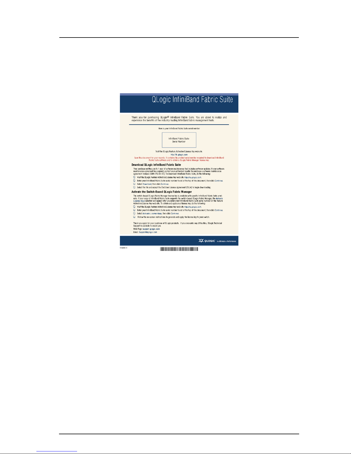
Switch-Based QLogic Fabric Manager License Key
Certain packages of the InfiniBand Fabric Suite entitle the user to the switch-based QLogic Fabric Manager. Refer to the
licensing documentation that comes with the InfiniBand Fabric Suite for instructions on generating the license key.
Figure 2. InfiniBand Fabric Suite Licensing Information
For detailed license key activation information, refer to the QLogic 12000 Hardware Installation Guide.
7
Page 8
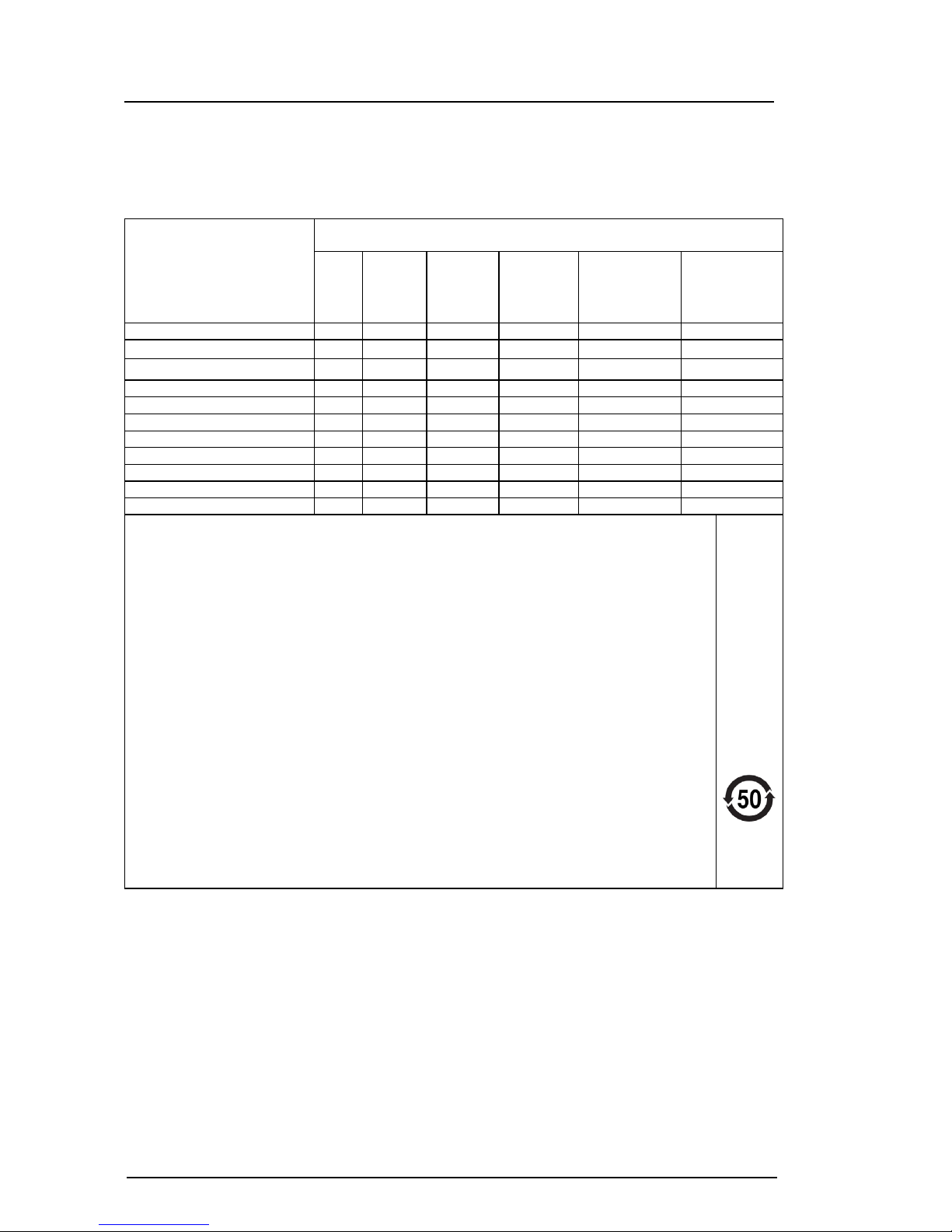
China RoHS Electronic Information
Table 2. China RoHS
Part Name * Toxic and Hazardous Substances and Elements
Lead
(Pb)
Printed circuit assembly 0 0 0 0 0 0
Internal power supply unit 0 0 0 0 0 0
Fan 0 0 0 0 0 0
AC power inlet 0 0 0 0 0 0
Cable and connector assemblies 0 0 0 0 0 0
Power cord 0 0 0 0 0 0
Enclosure and fasteners 0 0 0 0 0 0
EMI gasket 0 0 0 0 0 0
Optics module 0 0 0 0 0 0
Adapter unit 0 0 0 0 0 0
Mounting rails 0 0 0 0 0 0
Mercury
(Hg)
Cadmium
(Cd)
Hexavalent
Chromium
(Cr6+)
Polybrominated
Biphenyls
(PBB)
Polybrominated
dipheny ethers
(PBDE)
* If the listed part is present in this product, then the substances are as identified
in this table.
"0" indicates the hazardous and toxic substance content of the part (at the
homogenous material level) is lower than the threshold defined by
SJ/T11363-2006 (Electronic Information Product Virulent Deleterious Substance
Limits Quantity Request).
"X" indicates the hazardous and toxic substance content of the part (at the
homogenous material level) is over the threshold defined by SJ/T11363-2006
(Electronic Information Product Virulent Deleterious Substance Limits Quantity
Request).
In all cases where an X is shown, QLogic complies with the allowable exemption
summarized in Article 7 of the Directive 2002/95/EC of the European Parliament
And Of The Council of 27 January 2003.
The number identified within the EIP pollution control logo is based on normal
operating conditions.
8
Page 9

Table 3. China RoHS Translated
部件名称 * 有毒 , 有害物质和元素
印刷电路板
内接电源
风扇
电源插口
缆绳和连接器组件
电源线
机壳和螺钉固定件
EMI 垫圈
光学模块
转换器
安装轨道
铅
(Pb)
00 00 0 0
00 00 0 0
00 00 0 0
00 00 0 0
00 00 0 0
00 00 0 0
00 00 0 0
00 00 0 0
00 00 0 0
00 00 0 0
00 00 0 0
汞
(Hg)镉(Cd)
六价铬
(Cr6+)
多溴联苯
(PBB)
多溴二苯醚
* 表中列出此产品含有有毒和有害物质及元素的部件名称。
"0" 表示此部件使用的所有同类材料中,此种有毒和有害物质低
于 SJ/T11363-2006 标准规定的限制要求。
(PBDE)
"X" 表示此部件使用的所有同类材料中,此种有毒和有害物质
高于 SJ/T11363-2006 标准规定的限制要求。
此表中所有名称含 “X” 标志的部件均符合欧盟 RoHS 立法
— “2003 年 1 月 27 日欧洲议会和欧洲理事会关于在电气电子
设备中限制使用某些有害物质的指令 2002/95/EC” 。
—此 QLogic 产品符合欧盟豁免清单。
注:所引用的环保使用期限标记根据产品的正常操作使用条件
(如温度和湿度)确定。
9
Page 10

10
Page 11

© 2010 QLogic Corporation. QLogic, the QLogic logo, Enterprise Fabric Suite 2007 and SilverStorm are registered
trademarks or trademarks of QLogic Corporation. All other brands and product names are trademarks or registered
trademarks of their respective owners. Information supplied by QLogic is believed to be accurate and reliable. QLogic
Corporation assumes no responsibility for any errors in this brochure. QLogic Corporation reserves the right, without
notice, to makes changes in product design or specifications.
Page 12

Corporate Headquarters Europe Headquarters
QLogic Corporation QLogic (UK) LTD.
26650 Aliso Viejo Parkway Quatro House, Lyon Way, Frimley
Aliso Viejo, CA 92656 Camberley Surrey, GU16 7ER UK
949.389.6000 www.qlogic.com +44 (0) 1276 804 670
*D000136-001 B*
D000136-001 B
 Loading...