

Page 1
Please check PTZOPTICS.com for the most up to date version of this document Rev 1.2 5/18
PTZ Optics 30x SDI (Gen 2)
User Manual
Model Nos: PT30X-SDI-GY-G2 & PT30X-SDI-WH-G2
V1.2
(English)
Page 2

Page i of 46
Rev 1.2 5/18
Preface
Thank you for using the HD Professional Video Conferencing Camera. This manual introduces the function, installation and
operation of the HD camera. Prior to installation and usage, please read the manual thoroughly.
Precautions
This product can only be used in the specified conditions in order to avoid any damage to the camera:
• Don’t subject the camera to rain or moisture.
• Don’t remove the cover. Removal of the cover may result in an electric shock, in addition to voiding the warranty.
In case of abnormal operation, contact the manufacturer.
• Never operate outside of the specified operating temperature range, humidity, or with any other power supply
than the one originally provided with the camera.
• Please use a soft dry cloth to clean the camera. If the camera is very dirty, clean it with diluted neutral detergent;
do not use any type of solvents, which may damage the surface.
Note
This is an FCC Class A Digital device. As such, unintentional electromagnetic radiation may affect the image quality of TV in a
home environment.
Page 3

Page ii of 46
Rev 1.2 5/18
Table of Contents
1 Supplied Accessories ··································································································· 1
2 Notes ······················································································································ 1
3 Quick Start ··············································································································· 2
4 Features ··················································································································· 4
5 Product Specifications ·································································································· 5
6 Main Unit ················································································································· 7
7 IR Remote Controller ··································································································· 8
8 Using IR Remote Controller ·························································································· 10
9 Dimensional Drawings ································································································ 13
10 RS-232 Interface ······································································································· 14
11 Serial Communication Control ······················································································· 15
12 Menu Settings ··········································································································· 27
13 Network Connection ··································································································· 32
14 Maintenance and Troubleshooting ··················································································· 45
Page 4
Page 1 of 46
Rev 1.2 5/18
Supplied Accessories
When you unpack your camera, check that all the supplied accessories are included:
⚫ Camera .................................. 1
⚫ AC Power Adaptor ................ 1
⚫ Power Cord ........................... 1
⚫ RS232 Cable ......................... 1
⚫ IR Remote Controller ........... 1
⚫ User Manual ......................... 1
Notes
⚫ Electrical Safety
Installation and operation must be in accordance with national and local electric safety standards. Do not use any power
supply other than the one originally supplied with this camera.
⚫ Polarity of power supply
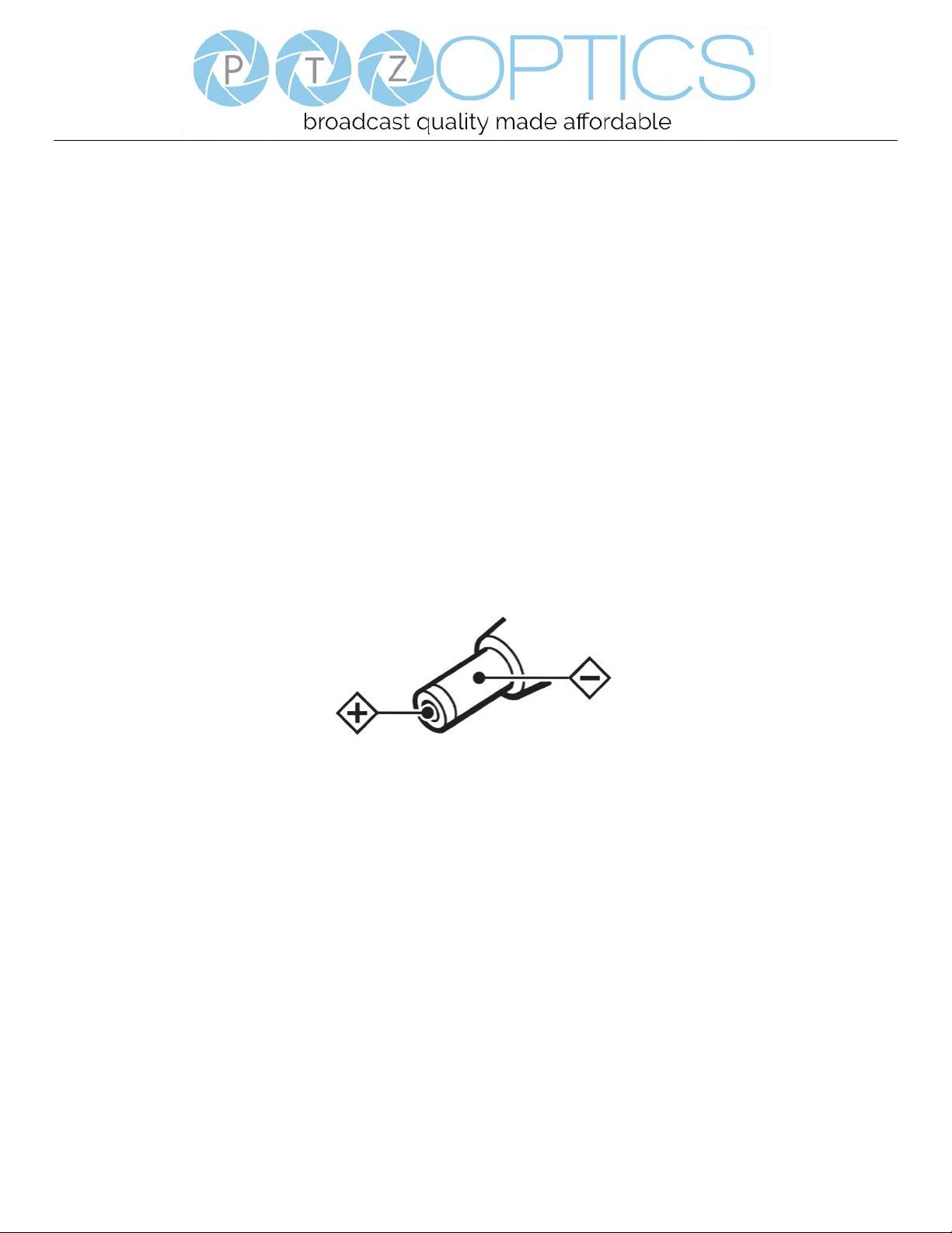
The power supply output for this product is 12VDC with a maximum current supply of 2A. Polarity of the power supply
plug is critical and is as follows.
⚫ Handling
◼ Avoid any stress, vibration, or moisture during transportation, storage, installation and operation.
◼ Do not lift or move the camera by grasping the camera head. Do not turn the camera head by hand. Doing so may
result in mechanical damage.
◼ Do not expose camera to any corrosive solid, liquid, or gas to avoid damage to the cover which is made of a plastic
material.
◼ Ensure that there are no obstacles in the tilt or pan ranges of the camera lens.
◼ Never power camera on before installation is complete.
◼ DO NOT DISMANTLE THE CAMERA – The manufacturer is not responsible for any unauthorized
modification or dismantling.
Page 5
Page 2 of 46
Rev 1.2 5/18
Quick Start
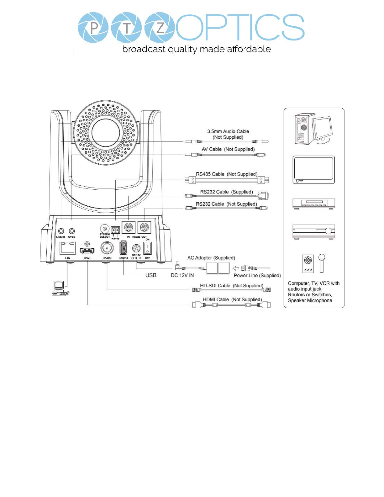
Step1. Please check that all connections are correct before powering on the camera.
Page 6

Page 3 of 46
Rev 1.2 5/18
Step2. Set the system select switch for your desired video output resolution and frame rate.
For many applications, setting 0 (1080p-60) will provide the best overall performance.
For highest possible resolution, use setting 0 (1080p-60) or 6 (1080p-30), however your actual realized frame rate may
be limited to a lower value than 60 fps by your software and/or network connection.
NOTE: After changing this dial, you need to restart the camera to see the effect. Turn the camera off.
VIDEO SYSTEM
0
1080p60
8
720p30
1
1080p50
9
720p25
2
1080i60
A - 3
1080i50
B - 4
720p60
C - 5
720p50
D
576i
6
1080p30
E
480i
7
1080p25
F
-
CAUTION: After changing the system (rotary) switch, you need to restart the camera to take effect.
Step3. Press the Switch ON button on the rear of the camera, the power lamp will illuminate.
Step4. The Pan-Tilt mechanism will rotate the lens to the maximum position of top right after the camera starts, then it will
return to the “center”. The process of initialization is now complete.
(Note: If the position preset 0 has been stored, the position preset 0 will be called up after initialization in lieu of “home”)
Step5. (Optional) If you want to restore the factory default settings, press [MENU] button to display the OSD menu. Select
the item [MENU] -> [RESTORE DEFAULT] -> [Restore].Set the value [Yes], press [HOME] button to restore the factory
default settings.
RESTORE DEFAULT
Restore Yes
Change Value
[Home] OK
[Menu] Back
Page 7

Page 4 of 46
Rev 1.2 5/18
Features
1. Supports simultaneous 3G-SDI, HDMI and IP network streaming for up to 1080P@60*.
2. Supports non-simultaneous CVBS (composite video) output via RCA connector (480i or 576i).
3. Includes Panasonic's high quality, 1/2.7 inch, 2.07 million effective pixels, HD CMOS sensor, which can produce a
maximum 1920 x 1080 image with a high quality, maximum output frame rate of 60 fps (frames per second).
4. Ultra-high frame rate 60fps for HDMI and SDI and up to 720@120fps for IP Streaming.
5. Supports IP streaming via RTSP and RTMP and using H.264, H.265and MJPEG.
6. Microphone & AAC Audio Stream Encoding for IP stream & HDMI – Use line-level microphone for line in input. Uses
AAC audio encoding for better sound quality and smaller bandwidth usage.
7. Includes a Tamron, high-quality, telephoto lens, supporting 30x optical zoom and optional 16x digital zoom with wide
angle 60.7 degree horizontal field of view in widest zoom setting.
8. The high SNR (signal to noise ratio) of the CMOS sensor (≥55dB), combined with 2D and 3D noise reduction algorithms,
effectively reduces noise, even under low illumination conditions.
9. Includes DRC (dynamic range control), allowing for greater image quality and detail across images that are both well-lit
and shadowed in the same frame.
10. Includes RS232 and RS485 interfaces for wired remote control. All of the parameters of the camera can be remotely
controlled by high-speed communications for joystick and central control system applications.
11. Includes web-based IP remote control interface.
12. Freeze - Allows freezing of video image on all outputs to allow for calling next preset without showing camera motion.
13. Power over Ethernet – Supports PoE 802.3af.
*Please note: The camera is unable to perform 1080@60 over IP stream & SDI/HDMI simultaneously
Page 8
Page 5 of 46
Rev 1.2 5/18
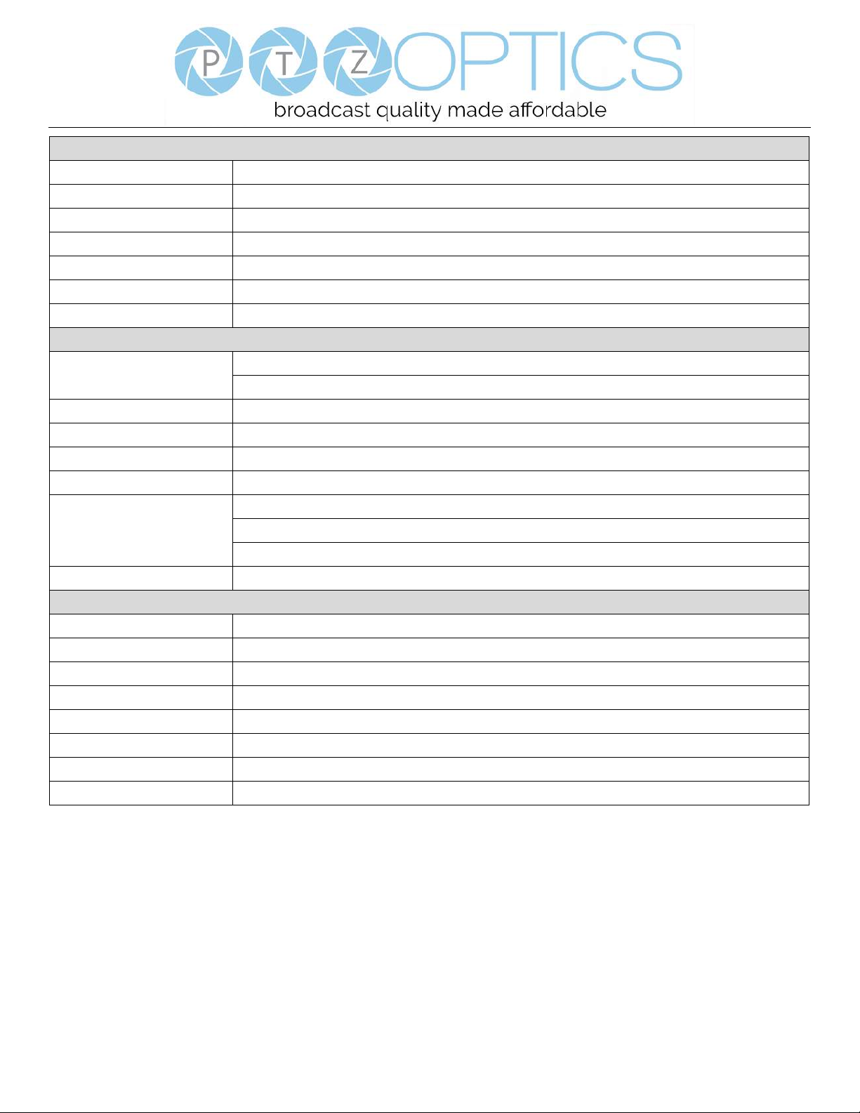
Product Specifications
Model
PT30X-SDI-GY-G2 and PT30X-SDI-WH-G2
Type
PTZOptics SDI HD 1080p Color Video Camera
Camera
Video System
HD: 1080p/60, 1080p/50, 1080i/60, 1080i/50, 1080p/30, 1080p/25, 720p/60, 720p/50, 720p30,
720p25 SD: NTSC, PAL
*Please note: The camera is unable to perform 1080@60 over IP stream & SDI/HDMI
simultaneously
Sensor
1/2.7", CMOS, Effective Pixel: 2.07M
Scanning Mode
Progressive
Lens
30x, f4.42mm ~ 88.5mm, F1.8 ~ F2.8
Digital Zoom
16x
Minimal Illumination
0.05 Lux @ (F1.8, AGC ON)
Shutter
1/30s ~ 1/10000s
White Balance
Auto, Indoor, Outdoor, One Push, Manual, VAR
Backlight Compensation
Support
Digital Noise Reduction
2D&3D Digital Noise Reduction
Video S/N
≥55dB
Horizontal Angle of View
3.36° ~ 60.7°
Vertical Angle of View
1.89° ~ 34.1°
Horizontal Rotation Range
±170°
Vertical Rotation Range
-30° ~ +90°
Pan Speed Range
1.7° ~ 100°/s
Tilt Speed Range
1.7° ~ 69.9°/s
H & V flip
Support
Image Freeze
Support
PoE
Support (802.3af)
Face Detection
Not Supported
Local Storage
Not Supported
Number of Preset
255
Preset Accuracy
0.1°
IPC Features
Video Coding Standard
H.264/H.265/MJPEG
Video Stream
First stream, Second stream
First Stream Resolution
1920x1080, 1280x720, 1024x576, 960x540, 640x480, 640x360
Page 9
Page 6 of 46
Rev 1.2 5/18
IPC Features
Second Stream Resolution
1280x720, 1024x576, 720x576, 720x408, 640x360, 480x270, 320x240, 320x180
Bit Rate
128Kbps ~ 8192Kbps
Bit Rate Type
Variable rate, fixed rate
Frame Rate
50Hz: 1fps ~ 50fps, 60Hz: 1fps ~ 60fps, 720p120: 120fps, 640x480p240: 240fps
Audio Standard
AAC
Audio Rate
96K, 128K, 256K
Support Protocols
TCP/IP, HTTP, RTSP, RTMP, Multicast, DHCP, ONVIF etc
Input/Output Interface
HD Output
1 x HDMI: Version 1.3
1 x HD-SDI: BNC type, 800mVp-p, 75Ω, Along to SMPTE 424M standard
SD Output
1 x CVBS: RCA jack, 1Vp-p, 75Ω
Network Interface
1 x RJ45: 10/100/1000M Adaptive Ethernet ports
Audio Input
1-ch 3.5mm audio interface, Line In
USB
1 x USB2.0: type A jack
Communication Interface
1 x RS-232 IN: 8pin Min DIN, Max Distance: 30m, Protocol: VISCA/Pelco-D/Pelco-P
1 x RS-232 OUT: 8pin Min DIN, Max Distance: 30m, Protocol: VISCA network use only
1 x RS-485: 2pin Phoenix port, Max Distance: 1200m, Protocol: VISCA/Pelco-D/Pelco-P
Power Jack
JEITA type (DC IN 12V)
Generic Specification
Input Voltage
DC 12V / PoE (802.3af) (optional)
Current Consumption
1.0A (Max)
Operating Temperature
-10°C ~ 40°C (14°F ~ 104°F)
Storage Temperature
-40°C ~ 60°C (-40°F ~ 140°F)
Power Consumption
12W (Max)
MTBF
>30000h
Size
169mm x 142mm x 164mm
Net Weight
1.35 Kg
Page 10
Page 7 of 46
Rev 1.2 5/18
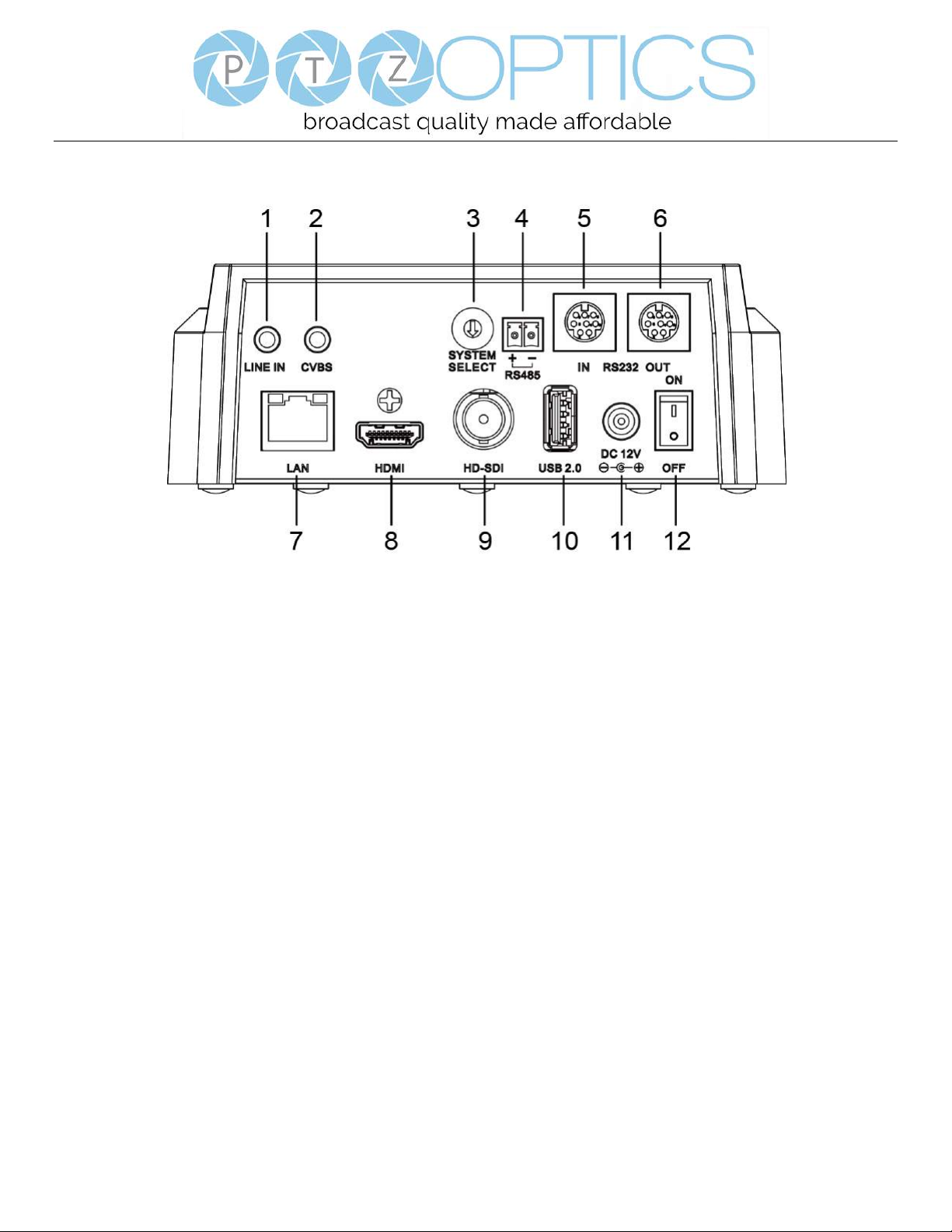
Main Unit
1.Audio LINE IN Interface (HDMI & IP) 7.Network (IP streaming & control)
2.CVBS (composite video SD) Interface 8.HDMI (Digital Video Output)
3.System select dial (resolution) 9.HD-SDI (Serial Digital Video Output)
4.RS485 jack 10.USB 2.0 (USB Storage)
5.RS232 IN jack 11.DC 12V power jack
6.RS232 OUT jack (pass through for daisy chain) 12.Power switch
Page 11
Page 8 of 46
Rev 1.2 5/18
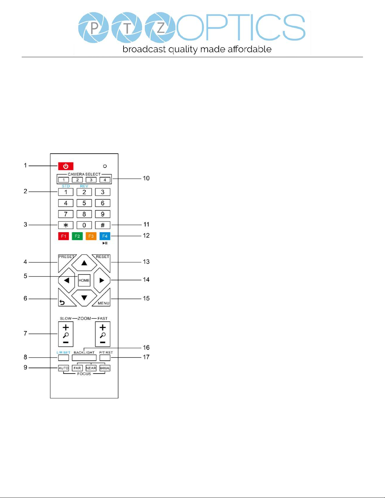
IR Remote Controller
1. Standby Button
Press this button to enter standby mode. Press it again to enter normal mode.
NOTE: Power consumption in standby mode is approximately half of the normal mode.
2. Position Buttons
To set preset or call preset.
3. * Button
For multiple function.
4&13. Set/Clear Preset Buttons
Set preset: Store a preset position
[PRESET] + Numeric button (0-9): Setting a corresponding numeric key
preset position
NOTE: Preset 0 - 9 via remote control and the rest from web, keyboard and
the serial port.
Clear preset: Erase a preset position [RESET] + Numeric button (0-9), or: [*]
+ [#] + [RESET]: Erase all presets
5&14. Pan/Tilt Control Buttons
Press the arrow buttons to perform panning and tilting. Press the [HOME]
button to face the camera back to front.
6. Return Button
Press the button to back previous menu.
7. Zoom Buttons
Zoom+: Zoom In (Slow and fast speed)
Zoom-: Zoom Out (Slow and fast speed)
8. L/R Set Button
Set the left & right direction of the remote control.
Simultaneously press [L/R Set] + [1]: Normal direction.
Simultaneously press [L/R Set] + [2]: Left and right direction will be
reversed.
9. Focus Buttons
Used for focus adjustment.
Press [AUTO] to adjust the focus on the center of the object automatically. To
adjust the focus manually, press the [MANUAL] button, and adjust it with
[Far] (focus on far object) and [Near] (focus on near object).
10. Camera Address Select Buttons
Press the button corresponding to the camera which you want to operate with the remote controller.
11. # Button
For multiple function.
Page 12

Page 9 of 46
Rev 1.2 5/18
12. Multiple Function Buttons
Function 1. Set camera IR address
Press 3 keys contiguously can set camera IR address as follow:
[*] + [#] + [F1]: Address 1
[*] + [#] + [F2]: Address 2
[*] + [#] + [F3]: Address 3
[*] + [#] + [F4]: Address 4
Function 2. Image freezing function
Press [F4] to start the freeze function. The word "Freeze" displays on the upper left corner. After five seconds, the display
disappears automatically (though the freeze feature continues). To cancel the freeze, press the [F4] key the word "Unfreeze"
displays on the upper left corner. After five seconds, the display disappears automatically.
15. Menu Button
Menu button: Press this button to enter or exit the OSD menu.
16. Backlight Button
Backlight button: Press this button to enable the backlight compensation. Press it again to disable the backlight compensation.
NOTE: Effective only in auto exposure mode.
NOTE: If there is a light behind the subject, the subject will appear dark. In this case, press the backlight ON / OFF button. To
cancel this function, press the backlight ON / OFF button.
17. P/T RST Button
Press the button to self-calibrate pan and tilt once again.
Shortcuts for some ‘Set’ Functions
[*] + [#] + [1]: Display OSD menu in English
[*] + [#] + [3]: Display OSD menu in Chinese
[*] + [#] + [4]: Show IP address
[*] + [#] + [6]: Quickly restore the default settings
[*] + [#] + [8]: Show the camera version
[*] + [#] + [9]: Quickly set mount mode (flip / normal) 1. Standby Button
Press this button to enter standby mode. Press it again to enter normal mode.
NOTE: Power consumption in standby mode is approximately half of the normal mode.
Page 13
Page 10 of 46
Rev 1.2 5/18
Using IR Remote Controller
When the camera is operational, you can use the remote
controller to perform panning, tilting, zooming and
focusing, as well as store and call back preset positions.
Button Instructions:
1. In these instructions, ‘press the button’ means to
press and release. A special note will be given if holding a
button down for more than one second is required.
2. When a button-combination is required, do it in
sequence (not simultaneously). For example, ‘[*] + [#] +
[F1]’means press [*] first and then press [#] and then
press [F1].
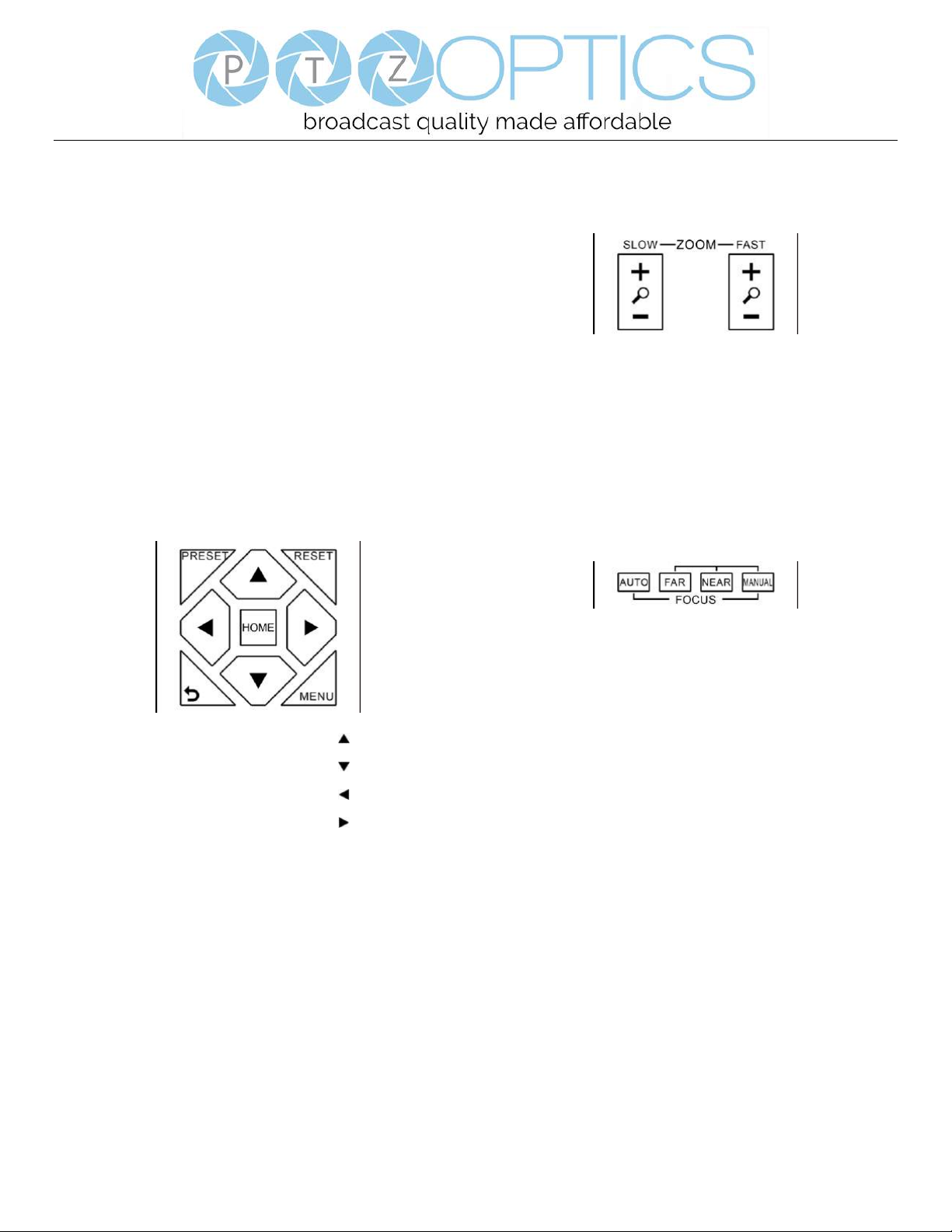
1. Pan/Tilt Control
Tilt up: Press [ ]
Tilt down: Press [ ]
Pan left: Press [ ]
Pan right: Press [ ]
Face the camera back to front: Press [HOME]
Press and hold the up/down/left/right buttons, to keep
panning or tilting from slow to fast, (until the camera
reaches the mechanical limit). The camera stops as soon
as the button is released.
2. Zoom Control
Zoom Out: press [+] button under FAST or SLOW
Zoom In: press [-] button under FAST or SLOW
Press and hold the button, to keep zooming in or out
(until the lens reaches the mechanical limit). The lens
stops as soon as the button is released.
3. Focus Control
AUTO: Change focus mode to AF, which allows the
camera to adjust the focus automatically on the center of
the image.
MANUAL: Change focus mode to MF, which allows the
user to adjust the focus manually (see FOCUS FAR &
FOCUSNEAR).
FOCUS FAR: Press [FAR] button(NOTE: Effective only
in MANUAL focus mode)
FOCUS NEAR: Press [NEAR] button(NOTE: Effective
only in MANUAL focus mode)
Press and hold the FOCUS [FAR] or FOCUS [NEAR]
button, allows for continuous adjustment, stopping as
soon as the button is released.
Page 14

Page 11 of 46
Rev 1.2 5/18
4. BACKLIGHT. L/R SET and P/T RST Controls
Reverse Pan controls direction: Press and hold [L/R SET]
button while pressing [1] aka [STD] button for normal
pan controls. Press and hold [L/R SET] button while
pressing [2] aka [REV] button for reversed pan controls.
Backlight Compensation Control: Press [BACKLIGHT]
button to enable backlight compensation. Press it again to
disable backlight compensation. (Note: Backlight is only
effective in full auto exposure mode)
Pan Tilt Control Self Calibration: Press [P/T RST] button
to recalibrate the Pan and Tilt limits.
5. Standby Control
Press [ ] button to put camera in ‘standby’ mode. In
standby mode the camera will provide no image, respond
to no commands and use less than half its normal power.
Press [ ] button again to put camera in normal mode.
6. Presets - Setting and Clearing
1. To store a preset position: The user should manually
setup the desired shot using the Pan Tilt and Zoom
controls. Press the [PRESET] button first and then press
the numeric button [0-9] to which you want to assign the
shot. Ten total preset positions (0-9) are available from
the IR remote control (255 available via RS232/RS485/IP
Interfaces).
2. To erase the memory content of a preset position: The
user should press the [RESET] button first and then press
the numeric button 0-9 associated with that preset.
Note:
Pressing [*]+[#]+[RESET]in sequence will erase all
presets in the memory.
Page 15

Page 12 of 46
Rev 1.2 5/18
7. Recalling Presets
Pressing any of the numeric buttons [0-9] directly will
recall a stored preset position and settings.
Note:
No action will be executed if a specific numeric preset
position has not yet been saved.
Note:
Presets assigned via the IP interface do not correlate to
presets set via the IR remote control.
8. Camera Selection
Press the [1-4] button corresponding to the camera with
the IR address that you want to operate. This allows for
up to 4 cameras to be operated via the same IR remote in
the same room.
9. Camera IR Address Set
Press 3 buttons in the sequence shown below to
set/change the camera’s IR address. This allows up to 4
cameras to be controlled from the same IR remote control.
Be sure that only one camera is picking up the IR signal
when you perform this function. If multiple cameras
receive the command, they will all change to the new
address.
Address1: [*]+[#]+[F1]
Address 2: [*]+[#]+[F2]
Address 3: [*]+[#]+[F3]
Address 4: [*]+[#]+[F4]
10. Image Freeze
Press the [ ] button to freeze or unfreeze the video
image. This can be useful while recalling presets to hide
camera motion from your viewers.
Page 16
Page 13 of 46
Rev 1.2 5/18
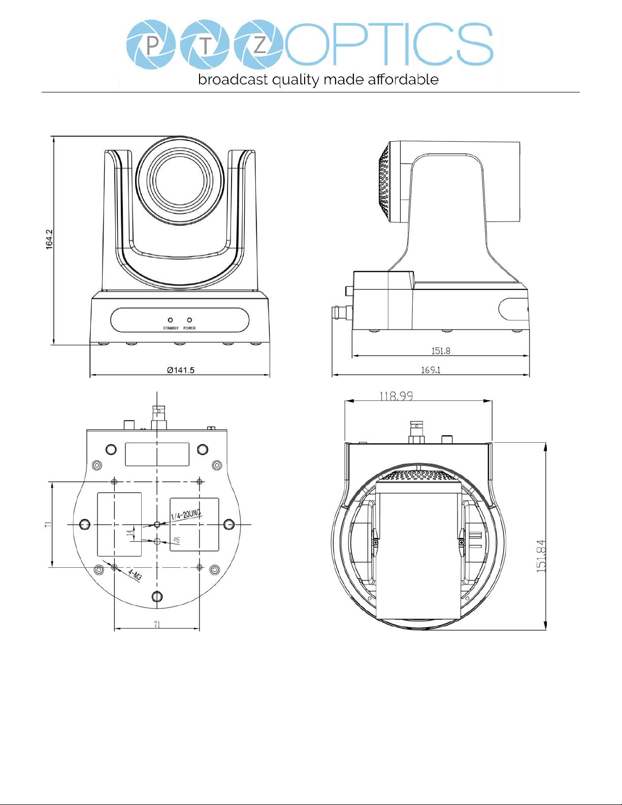
Dimensional Drawings (mm)
Page 17
Page 14 of 46
Rev 1.2 5/18
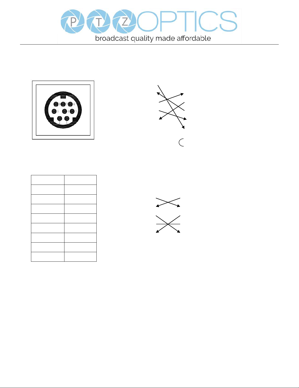
RS-232 Interface
Camera PC/Controller DB-9
1.DTR 1.CD
2.DSR 2.RXD
3.TXD 3.TXD
4.GND 4.DTR
5.RXD 5.GND
6.GND 6.DSR
7.IR OUT 7.RTS
8.NC 8.CTS
9.RI
For Control Daisy Chain
1
st
Camera 2nd Camera Mini DIN
1.DTR 1.DTR
2.DSR 2.DSR
3.TXD 3.TXD
4.GND 4.GND
5.RXD 5.RXD
6.GND 6.GND
7.IR OUT 7.NC
8.NC 8.NC
No.
Function
1
DTR
2
DSR 3 TXD
4
GND
5
RXD
6
GND
7
IR OUT
8
NC
Page 18

Page 15 of 46
Rev 1.2 5/18
Serial Communication Control
In default working mode, the camera is able to connect to a VISCA controller with an RS232C serial interface.
➢ RS232 Communication Control
The camera can be controlled via RS232. The parameters of RS232C are as follows:
Baud rate: 2400, 4800, 9600 or 38400 bps.
Start bit: 1 bit.
Data bit: 8 bits.
Stop bit: 1bit.
Parity bit: none.
➢ RS485 Communication Control
The camera can be controlled via RS485, Half-duplex mode, with support for VISCA, Pelco-D or Pelco-P protocol.
The parameters of RS485 are as follows:
Baud rate: 2400, 4800, 9600 or 38400 bps.
Start bit: 1 bit.
Data bit: 8 bits.
Stop bit: 1 bit.
Parity bit: none.
When powered on, Pan and Tilt will rotate to the maximum position of top right after the camera powered up. Then it will
return to the “center”. The process of initialization is now complete. (Note: If the position preset 0 has been stored, the
position preset 0 will be called up after initialization, in lieu of “center”). After initialization is complete, then the user can
control the camera with commands in the command list.
Page 19
Page 16 of 46
Rev 1.2 5/18
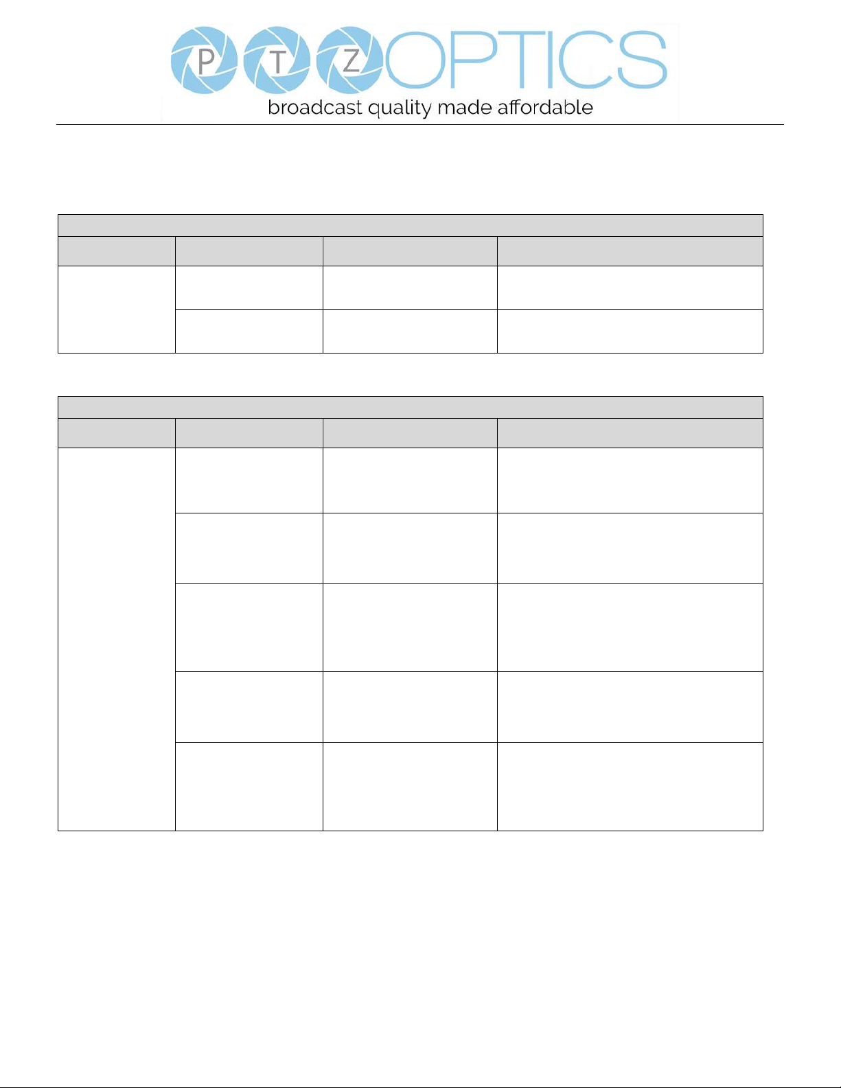
VISCA Command List
Part 1: Camera-Issued Messages
ACK/Completion Message
Command
Function
Command Packet
Comments
ACK/Completion
Messages
ACK
z0 4y FF
(y: Socket No.)
Returned when the command is accepted.
Completion
z0 5y FF
(y: Socket No.)
Returned when the command has been executed.
z = Camera Address + 8
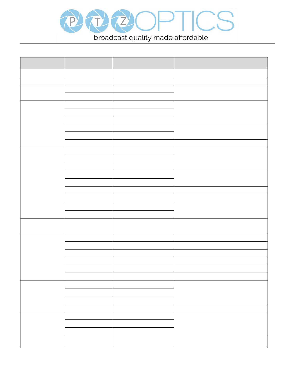
Error Messages
Command
Function
Command Packet
Comments
Error Messages
Syntax Error
z0 60 02 FF
Returned when the command format is different
or when a command with illegal command
parameters is accepted.
Command Buffer Full
z0 60 03 FF
Indicates that two sockets are already being used
(executing two commands) and the command
could not be accepted when received.
Command Canceled
z0 6y 04 FF
(y: Socket No.)
Returned when a command which is being
executed in a socket specified by the cancel
command is canceled. The completion message
for the command is not returned.
No Socket
z0 6y 05 FF
(y: Socket No.)
Returned when no command is executed in a
socket specified by the cancel command, or when
an invalid socket number is specified.
Command Not Executable
z0 6y 41 FF
(y: Execution command Socket
No. Inquiry command: 0)
Returned when a command cannot be executed
due to current conditions. For example, when
commands controlling the focus manually are
received during auto focus.
Page 20
Page 17 of 46
Rev 1.2 5/18
Part 2: Camera Control Commands
Command
Function
Command Packet
Comments
AddressSet
Broadcast
88 30 01 FF
Address setting
IF_Clear
Broadcast
88 01 00 01 FF
I/F Clear
CAM_Power
On
8x 01 04 00 02 FF
Power ON/OFF
Off
8x 01 04 00 03 FF
CAM_Zoom
Stop
8x 01 04 07 00 FF
Tele(Standard)
8x 01 04 07 02 FF
Wide(Standard)
8x 01 04 07 03 FF
Tele(Variable)
8x 01 04 07 2p FF
p = 0(low) - 7(high)
Wide(Variable)
8x 01 04 07 3p FF
Direct
8x 01 04 47 0p 0q 0r 0s FF
pqrs: Zoom Position
CAM_Focus
Stop
8x 01 04 08 00 FF
Far(Standard)
8x 01 04 08 02 FF
Near(Standard)
8x 01 04 08 03 FF
Far(Variable)
8x 01 04 08 2p FF
p = 0(low) - 7(high)
Near(Variable)
8x 01 04 08 3p FF
Direct
8x 01 04 48 0p 0q 0r 0s FF
pqrs: Focus Position
Auto Focus
8x 01 04 38 02 FF
AF On/Off
Manual Focus
8x 01 04 38 03 FF
Auto/Manual
8x 01 04 38 10 FF
CAM_ZoomFocus
Direct
8x 01 04 47 0p 0q 0r 0s
0t 0u 0v 0w FF
pqrs: Zoom Position
tuvw: Focus Position
CAM_WB
Auto
8x 01 04 35 00 FF
Normal Auto
Indoor mode
8x 01 04 35 01 FF
Indoor mode
Outdoor mode
8x 01 04 35 02 FF
Outdoor mode
OnePush mode
8x 01 04 35 03 FF
One Push WB mode
Manual
8x 01 04 35 05 FF
Manual Control mode
OnePush trigger
8x 01 04 10 05 FF
One Push WB Trigger
CAM_RGain
Reset
8x 01 04 03 00 FF
Manual Control of R Gain
Up
8x 01 04 03 02 FF
Down
8x 01 04 03 03 FF
Direct
8x 01 04 43 00 00 0p 0q FF
pq: R Gain
CAM_Bgain
Reset
8x 01 04 04 00 FF
Manual Control of B Gain
Up
8x 01 04 04 02 FF
Down
8x 01 04 04 03 FF
Direct
8x 01 04 44 00 00 0p 0q FF
pq: B Gain
Page 21
Page 18 of 46
Rev 1.2 5/18
CAM_AE
Full Auto
8x 01 04 39 00 FF
Automatic Exposure mode
Manual
8x 01 04 39 03 FF
Manual Control mode
Shutter priority
8x 01 04 39 0A FF
Shutter Priority Automatic Exposure mode
Iris priority
8x 01 04 39 0B FF
Iris Priority Automatic Exposure mode
Bright
8x 01 04 39 0D FF
Bright Mode(Manual control)
CAM_SlowShutter
AutoSlowShutterLimit
8x 01 04 2A 0p 00 FF
CAM_Iris
Reset
8x 01 04 0B 00 FF
Iris Setting
Up
8x 01 04 0B 02 FF
Down
8x 01 04 0B 03 FF
Direct
8x 01 04 4B 00 00 0p 0q FF
pq: Iris Position
CAM_Gain
Reset
8x 01 04 0C 00 FF
Gain Setting
Up
8x 01 04 0C 02 FF
Down
8x 01 04 0C 03 FF
Direct
8x 01 04 0C 00 00 0p 0q FF
pq: Gain Position
Gain Limit
8x 01 04 2C 0p FF
p: Gain Position
CAM_Bright
Reset
8x 01 04 0D 00 FF
Bright Setting
Up
8x 01 04 0D 02 FF
Down
8x 01 04 0D 03 FF
Direct
8x 01 04 0D 00 00 0p 0q FF
pq: Bright Position
CAM_ExpComp
On
8x 01 04 3E 02 FF
Exposure Compensation On/Off
Off
8x 01 04 3E 03 FF
Reset
8x 01 04 0E 00 FF
Exposure Compensation Amount Setting
Up
8x 01 04 0E 02 FF
Down
8x 01 04 0E 03 FF
Direct
8x 01 04 4E 00 00 0p 0q FF
pq: ExpComp Position
CAM_BackLight
On
8x 01 04 33 02 FF
Back Light Compensation On/Off
Off
8x 01 04 33 03 FF
CAM_NR(2D)Mode
Auto
8x 01 04 50 02 FF
ND2D Auto/Manual
Manual
8x 01 04 50 03 FF
CAM_NR(2D)Level
-
8x 01 04 53 0p FF
p: NR Setting (0: Off, level 1 to 5)
CAM_NR(3D)Level
-
8x 01 04 54 0p FF
p: NR Setting (0: Off, level 1 to 8)
CAM_Flicker
-
8x 01 04 23 0p FF
p: Flicker Settings
(0: Off, 1: 50Hz, 2: 60Hz)
CAM_DHotPixel
-
8x 01 04 56 0p FF
p: Dynamic Hot Pixel Setting (0: 0ff, level 1 to 6)
CAM_ApertureMode(
sharpness)
Auto
8x 01 04 05 02 FF
Sharpness Auto
Manual
8x 01 04 05 02 FF
Sharpness Manual
Page 22
Page 19 of 46
Rev 1.2 5/18
CAM_Aperture(sharp
ness)
Reset
8x 01 04 02 00 FF
Aperture Control
Up
8x 01 04 02 02 FF
Down
8x 01 04 02 03 FF
Direct
8x 01 04 42 00 00 0p 0q FF
pq: Aperture Gain
CAM_PictureEffect
Off
8x 01 04 63 00 FF
Picture Effect Setting
B&W
8x 01 04 63 04 FF
CAM_Memory
Reset
8x 01 04 3F 00 pp FF
pp: Memory Number(=0 to 127)
Set
8x 01 04 3F 01 pp FF
Recall
8x 01 04 3F 02 pp FF
CAM_LR_Reverse
On
8x 01 04 61 02 FF
Image Flip Horizontal On/Off
Off
8x 01 04 61 03 FF
CAM_PictureFlip
On
8x 01 04 66 02 FF
Image Flip Vertical On/Off
Off
8x 01 04 66 03 FF
CAM_RegisterValue
-
8x 01 04 24 mn 0p 0q FF
mm: Register No. (=00-7F)
pp: Register Value (=00-7F)
CAM_ColorGain
Diret
8x 01 04 49 00 00 00 0p FF
p: Color Gain setting 0h (60%) to Eh (200%)
SYS_Menu
Off
8x 01 06 06 03 FF
Turns off the menu screen
Pan_tiltDrive
Up
8x 01 06 01 VV WW 03 01 FF
VV: Pan speed 0x01 (low speed) to 0x18 (high
speed)
WW: Tilt speed 0x01 (low speed) to 0x14 (high
speed)
YYYY: Pan Position
ZZZZ: Tilt Position
Down
8x 01 06 01 VV WW 03 02 FF
Left
8x 01 06 01 VV WW 01 03 FF
Right
8x 01 06 01 VV WW 02 03 FF
Upleft
8x 01 06 01 VV WW 01 01 FF
Upright
8x 01 06 01 VV WW 02 01 FF
DownLeft
8x 01 06 01 VV WW 01 02 FF
DownRight
8x 01 06 01 VV WW 02 02 FF
Stop
8x 01 06 01 VV WW 03 03 FF
AbsolutePosition
8x 01 06 02 VV WW
0Y 0Y 0Y 0Y 0Z 0Z 0Z 0Z FF
RelativePosition
8x 01 06 03 VV WW
0Y 0Y 0Y 0Y 0Z 0Z 0Z 0Z FF
Home
8x 01 06 04 FF
Reset
8x 01 06 05 FF
Pan_tiltLimitSet
LimitSet
8x 01 06 07 00 0W
0Y 0Y 0Y 0Y 0Z 0Z 0Z 0Z FF
W: 1 UpRight 0: DownLeft
YYYY: Pan Limit Position
ZZZZ: Tilt Position
LimitClear
8x 01 06 07 01 0W
07 0F 0F 0F 07 0F 0F 0F FF
CAM_AFSensitivity
High
8x 01 04 58 01 FF
AF Sensitivity High/Normal/Low
Normal
8x 01 04 58 02 FF
Page 23
Page 20 of 46
Rev 1.2 5/18
Low
8x 01 04 58 03 FF
CAM_SettingReset
Reset
8x 01 04 A0 10 FF
Reset Factory Setting
CAM_Brightness
Direct
8x 01 04 A1 00 00 0p 0q FF
pq: Brightness Position
CAM_Contrast
Direct
8x 01 04 A2 00 00 0p 0q FF
pq: Contrast Position
CAM_Flip
Off
8x 01 04 A4 00 FF
Single Command For Video Flip
Flip-H
8x 01 04 A4 01 FF
Flip-V
8x 01 04 A4 02 FF
Flip-HV
8x 01 04 A4 03 FF
CAM_SettingSave
Save
8x 01 04 A5 10 FF
Save Current Setting
CAM_Iridix
Direct
8x 01 04 A7 00 00 0p 0q FF
pq: Iridix Position
CAM_AWBSensitivit
y
High
8x 01 04 A9 00 FF
High
Normal
8x 01 04 A9 01 FF
Normal
Low
8x 01 04 A9 02 FF
Low
CAM_AFZone
Top
8x 01 04 AA 00 FF
AF Zone weight select
Center
8x 01 04 AA 01 FF
Bottom
8x 01 04 AA 02 FF
CAM_ColorHue
Direct
8x 01 04 4F 00 00 00 0p FF
p: Color Hue setting 0h (− 14 degrees) to Eh ( +14
degrees
Page 24
Page 21 of 46
Rev 1.2 5/18
Part 3: Query Commands
Inquiry Command List
Command
Command packed
Inquiry Packet
Comments
CAM_PowerInq
8x 09 04 00 FF
y0 50 02 FF
On
y0 50 03 FF
Off(Standby)
y0 50 04 FF
Internal power circuit error
CAM_ZoomPosInq
8x 09 04 47 FF
y0 50 0p 0q 0r 0s FF
pqrs: Zoom Position
CAM_FocusAFMode
Inq
8x 09 04 38 FF
y0 50 02 FF
Auto Focus
y0 50 03 FF
Manual Focus
CAM_FocusPosInq
8x 09 04 48 FF
y0 50 0p 0q 0r 0s FF
pqrs: Focus Position
CAM_WBModeInq
8x 09 04 35 FF
y0 50 00 FF
Auto
y0 50 01 FF
Indoor mode
y0 50 02 FF
Outdoor mode
y0 50 03 FF
OnePush mode
y0 50 05 FF
Manual
CAM_RGainInq
8x 09 04 43 FF
y0 50 00 00 0p 0q FF
pq: R Gain
CAM_BGainInq
8x 09 04 44 FF
y0 50 00 00 0p 0q FF
pq: B Gain
CAM_AEModeInq
8x 09 04 39 FF
y0 50 00 FF
Full Auto
y0 50 03 FF
Manual
y0 50 0A FF
Shutter priority
y0 50 0B FF
Iris priority
y0 50 0D FF
Bright
CAM_ShutterPosInq
8x 09 04 4A FF
y0 50 00 00 0p 0q FF
pq: Shutter Position
CAM_IrisPosInq
8x 09 04 4B FF
y0 50 00 00 0p 0q FF
pq: Iris Position
CAM_BrightPosInq
8x 09 04 4D FF
y0 50 00 00 0p 0q FF
pq: Bright Position
CAM_ExpCompMod
eInq
8x 09 04 3E FF
y0 50 02 FF
On
y0 50 03 FF
Off
CAM_ExpCompPosI
nq
8x 09 04 4E FF
y0 50 00 00 0p 0q FF
pq: ExpComp Position
CAM_BacklightMode
Inq
8x 09 04 33 FF
y0 50 02 FF
On
y0 50 03 FF
Off
CAM_Nosise2DMode
Ing
8x 09 04 50 FF
y0 50 02 FF
Auto Noise 2D
y0 50 03 FF
Manual Noise 3D
CAM_Nosise2DLevel
8x 09 04 53 FF
y0 50 0p FF
Noise Reduction (2D) p: 0 to 5
CAM_Noise3DLevel
8x 09 04 54 FF
y0 50 0p FF
Noise Reduction (3D) p: 0 to 8
CAM_FlickerModeIn
q
8x 09 04 55 FF
y0 50 0p FF
p: Flicker Settings(0: OFF, 1: 50Hz, 2: 60Hz)
y0 50 02 FF
Auto Sharpness
Page 25
Page 22 of 46
Rev 1.2 5/18
CAM_ApertureModeI
nq(Sharpness)
8x 09 04 05 FF
y0 50 03 FF
Manual Sharpness
CAM_ApertureInq(Sh
arpness)
8x 09 04 42 FF
y0 50 00 00 0p 0q FF
pq: Aperture Gain
CAM_PictureEffectM
odeInq
8x 09 04 63 FF
y0 50 02 FF
Off
y0 50 04 FF
B&W
CAM_MemoryInq
8x 09 04 3F FF
y0 50 0p FF
p: Memory number last operated.
SYS_MenuModeInq
8x 09 06 06 FF
y0 50 02 FF
On
y0 50 03 FF
Off
CAM_LR_ReverseInq
8x 09 04 61 FF
y0 50 02 FF
On
y0 50 03 FF
Off
CAM_PictureFlipInq
8x 09 04 66 FF
y0 50 02 FF
On
y0 50 03 FF
Off
CAM_RegisterValueI
nq
8x 09 04 24 mm FF
y0 50 0p 0p ff
mm: Register No. (00 to FF) pp: Register Value
(00 to FF)
CAM_ColorGainInq
8x 09 04 49 FF
y0 50 00 00 00 0p FF
p: Color Gain setting 0h (60%) to Eh (200%)
CAM_IDInq
8x 09 04 22 FF
y0 50 0p 0q 0r 0s FF
pqrs: Camera ID
CAM_VersionInq
8x 09 00 02 FF
y0 50 ab cd
mn pq rs tu vw FF
ab: Factory Code(00: VHD, 01:MR, 08:T)
cd: Hardware Version
mnpq: ARM Version
rstu: FPGA Version
vw: Camera model
01: C Type
02: M Type
03: S Type
VideoSystemInq
8x 09 06 23 FF
y0 50 00 FF
1920x1080i60
y0 50 01 FF
1920x1080p30
y0 50 02 FF
1280x720p60
y0 50 04 FF
NTSC
y0 50 05 FF
NTSC
y0 50 06 FF
NTSC
y0 50 07 FF
1920x1080p60
y0 50 08 FF
1920x1080i50
y0 50 09 FF
1920x1080p25
y0 50 0A FF
1280x720p50
y0 50 0C FF
PAL
y0 50 0D FF
PAL
Page 26
Page 23 of 46
Rev 1.2 5/18
y0 50 0E FF
PAL
IR_Receive
8x 09 06 08 FF
y0 50 02 FF
On
y0 50 03 FF
Off
Pan-tiltMaxSpeedInq
8x 09 06 11 FF
y0 50 ww zz FF
ww: Pan Max Speed
zz: Tilt Max Speed
Pan-tiltPosInq
8x 09 06 12 FF
y0 50 0w 0w 0w 0w
0z 0z 0z 0z FF
wwww: Pan Position
zzzz: Tilt Position
CAM_TypeInq
8x 09 00 03 FF
y0 50 01 FF
C Type
y0 50 02 FF
M Type
y0 50 03 FF
S Type
CAM_DateInq
8x 09 00 04 FF
y0 50 0r ss uu uu vv ww 0D FF
Version dater: Big Version Numbers: Little
Version Numberuuuu: Yearvv: Monthww: Day
CAM_ModeInq
8x 09 04 A6 FF
y0 50 00 FF
Mode0
y0 50 02 FF
Mode2
CAM_GainLimitInq
8x 09 04 2C FF
y0 50 0q FF
p: Gain Limit
CAM_DHotPixelInq
8x 09 04 56 FF
y0 50 0q FF
p: Dynamic Hot Pixel Setting (0: 0ff, level 1 to 6)
CAM_AFSensitivityI
nq
8x 09 04 58 FF
y0 50 01 FF
High
y0 50 02 FF
Normal
y0 50 03 FF
Low
CAM_BrightnessInq
8x 09 04 A1 FF
y0 50 00 00 0p 0q FF
pq: Brightness Position
CAM_ContrastInq
8x 09 04 A2 FF
y0 50 00 00 0p 0q FF
pq: Contrast Position
CAM_FlipInq
8x 09 04 A4 FF
y0 50 00 FF
Off
y0 50 01 FF
Flip-H
y0 50 02 FF
Flip-V
y0 50 03 FF
Flip-HV
CAM_IridixInq
8x 09 04 A7 FF
y0 50 00 00 0p 0q FF
pq: Iridix Position
CAM_AFZone
8x 09 04 AA FF
y0 50 00 FF
Top
y0 50 01 FF
Center
y0 50 02 FF
Bottom
CAM_ColorHueInq
8x 09 04 4F FF
y0 50 00 00 00 0p FF
p: Color Hue setting 0h (− 14 degrees) to Eh ( +14
degrees
CAM_AWBSensitivit
yInq
8x 09 04 A9 FF
y0 50 00 FF
High
y0 50 01 FF
Normal
y0 50 02 FF
Low
Page 27
Page 24 of 46
Rev 1.2 5/18
Block Inquiry Command List
Command
Command packed
Inquiry Packet
Comments
CAM_LensBlockInq
8x 09 7E 7E 00 FF
y0 50 0u 0u 0u 0u 00 00 0v 0v
0v 0v 00 0w 00 FF
uuuu: Zoom Position
vvvv: Focus Position
w.bit0: Focus Mode 1: Auto 0: Manual
CAM_CameraBlockIn
q
8x 09 7E 7E 01 FF
y0 50 0p 0p 0q 0q 0r 0s tt 0u vv
ww 00 xx 0z FF
pp: R_Gain
qq: B_Gain
r: WB Mode
s: Aperture
tt: AE Mode
u.bit2: Back Light
u.bit1: Exposure Comp.
vv: Shutter Position
ww: Iris Position
xx: Bright Position
z: Exposure Comp. Position
CAM_OtherBlockInq
8x 09 7E 7E 02 FF
y0 50 0p 0q 00 0r 00 00 00 00
00 00 00 00 00 FF
p.bit0: Power 1:On, 0:Off
q.bit2: LR Reverse 1:On, 0:Off
r.bit3~0: Picture Effect Mode
CAM_EnlargementBl
ockInq
8x 09 7E 7E 03 FF
y0 50 00 00 00 00 00 00 00 0p
0q rr 0s 0t 0u FF
p: AF sensitivity
q.bit0: Picture flip(1:On, 0:Off)
rr.bit6~3: Color Gain(0h(60%) to Eh(200%))
s: Flip(0: Off, 1:Flip-H, 2:Flip-V, 3:Flip-HV)
t.bit2~0: NR2D Level
u: Gain Limit
Note:
The [x] in the above table is the camera address, [y] = [x + 8].
Page 28
Page 25 of 46
Rev 1.2 5/18
Pelco-D Protocol Command List
Function
Byte1
Byte2
Byte3
Byte4
Byte5
Byte6
Byte7
Up
0xFF
Address
0x00
0x08
Pan Speed
Tilt Speed
SUM
Down
0xFF
Address
0x00
0x10
Pan Speed
Tilt Speed
SUM
Left
0xFF
Address
0x00
0x04
Pan Speed
Tilt Speed
SUM
Right
0xFF
Address
0x00
0x02
Pan Speed
Tilt Speed
SUM
Zoom In
0xFF
Address
0x00
0x20
0x00
0x00
SUM
Zoom Out
0xFF
Address
0x00
0x40
0x00
0x00
SUM
Focus Far
0xFF
Address
0x00
0x80
0x00
0x00
SUM
Focus Near
0xFF
Address
0x01
0x00
0x00
0x00
SUM
Set Preset
0xFF
Address
0x00
0x03
0x00
Preset ID
SUM
Clear Preset
0xFF
Address
0x00
0x05
0x00
Preset ID
SUM
Call Preset
0xFF
Address
0x00
0x07
0x00
Preset ID
SUM
Auto Focus
0xFF
Address
0x00
0x2B
0x00
0x01
SUM
Manual Focus
0xFF
Address
0x00
0x2B
0x00
0x02
SUM
Query Pan Position
0xFF
Address
0x00
0x51
0x00
0x00
SUM
Query Pan Position Response
0xFF
Address
0x00
0x59
Value High
Byte
Value Low
Byte
SUM
Query Tilt Position
0xFF
Address
0x00
0x53
0x00
0x00
SUM
Query Tilt Position Response
0xFF
Address
0x00
0x5B
Value High
Byte
Value Low
Byte
SUM
Query Zoom Position
0xFF
Address
0x00
0x55
0x00
0x00
SUM
Query Zoom Position
Response
0xFF
Address
0x00
0x5D
Value High
Byte
Value Low
Byte
SUM
Page 29
Page 26 of 46
Rev 1.2 5/18
Pelco-P Protocol Command List
Function
Byte1
Byte2
Byte3
Byte4
Byte5
Byte6
Byte7
Byte8
Up
0xA0
Address
0x00
0x08
Pan Speed
Tilt Speed
0xAF
XOR
Down
0xA0
Address
0x00
0x10
Pan Speed
Tilt Speed
0xAF
XOR
Left
0xA0
Address
0x00
0x04
Pan Speed
Tilt Speed
0xAF
XOR
Right
0xA0
Address
0x00
0x02
Pan Speed
Tilt Speed
0xAF
XOR
Zoom In
0xA0
Address
0x00
0x20
0x00
0x00
0xAF
XOR
Zoom Out
0xA0
Address
0x00
0x40
0x00
0x00
0xAF
XOR
Focus Far
0xA0
Address
0x00
0x80
0x00
0x00
0xAF
XOR
Focus Near
0xA0
Address
0x01
0x00
0x00
0x00
0xAF
XOR
Set Preset
0xA0
Address
0x00
0x03
0x00
Preset ID
0xAF
XOR
Clear Preset
0xA0
Address
0x00
0x05
0x00
Preset ID
0xAF
XOR
Call Preset
0xA0
Address
0x00
0x07
0x00
Preset ID
0xAF
XOR
Auto Focus
0xA0
Address
0x00
0x2B
0x00
0x01
0xAF
XOR
Manual Focus
0xA0
Address
0x00
0x2B
0x00
0x02
0xAF
XOR
Query Pan Position
0xA0
Address
0x00
0x51
0x00
0x00
0xAF
XOR
Query Pan Position
Response
0xA0
Address
0x00
0x59
Value High
Byte
Value Low
Byte
0xAF
XOR
Query Tilt Position
0xA0
Address
0x00
0x53
0x00
0x00
0xAF
XOR
Query Tilt Position
Response
0xA0
Address
0x00
0x5B
Value High
Byte
Value Low
Byte
0xAF
XOR
Query Zoom Position
0xA0
Address
0x00
0x55
0x00
0x00
0xAF
XOR
Query Zoom Position
Response
0xA0
Address
0x00
0x5D
Value High
Byte
Value Low
Byte
0xAF
XOR
Page 30
Page 27 of 46
Rev 1.2 5/18
Menu Settings
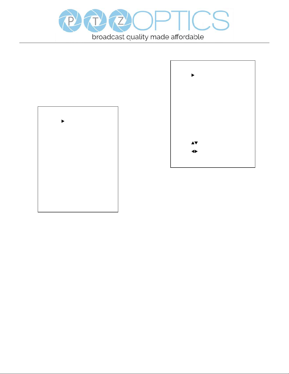
1. MENU
Press [MENU] button to display the main menu on the
normal screen, using arrow button to move the cursor to
the item to be set. Press the [HOME] button to enter the
corresponding sub-menu.
2. EXPOSURE
Move the main menu cursor to [EXPOSURE], and press
[HOME] key enter the exposure page, as shown in the
following figure.
Mode: Exposure mode, optional items: Auto, Manual,
SAE, AAE, Bright.
ExpCompMode: Exposure compensation mode, optional
items: On, Off (Effective only in Auto mode).
ExpComp: Exposure compensation value, optional items:
-7~7 (Effective only in ExpCompMode item to On).
Backlight: Set the backlight compensation, optional
items: On, Off (Effective only in Auto mode).
Bright: Intensity control, optional items: 00~17
(Effective only in Bright mode).
Gain Limit: Maximum gain limit, optional items: 0 ~ 15
(Effective only in Auto, AAE, Bright mode).
Anti-Flicker: Anti-flicker, optional items: Off, 50Hz,
60Hz (Effective only in Auto, Bright mode).
Meter: optional items: Average, Center, Bottom, Top.
Iris: Aperture value, optional items: F1.8, F2.0, F2.4,
F2.8, F3.4, F4.0, F4.8, F5.6, F6.8, F8.0, F9.6, F11.0,
Close (Effective only in Manual, AAE mode).
EXPOSURE
Mode Auto
ExpCompMode Off
Backlight Off
Gain Limit 3
Anti-Flicker 60Hz
Meter Average
DRC 2
Select Item
Change Value
[Menu] Back
MENU
Exposure
Color
Image
P/T/Z
Noise Reduction
Setup
Communication Setup
Restore Default
[Home] Enter
[Menu] Exit
Page 31
Page 28 of 46
Rev 1.2 5/18
Shutt: Shutter value, optional items: 1/30, 1/60, 1/90,
1/100, 1/125, 1/180, 1/250, 1/350, 1/500, 1/725, 1/1000,
1/1500, 1/2000, 1/3000, 1/4000, 1/6000, 1/10000
(Effective only in Manual, SAE mode).
DRC: DRC strength, optional items: 0 ~ 8.
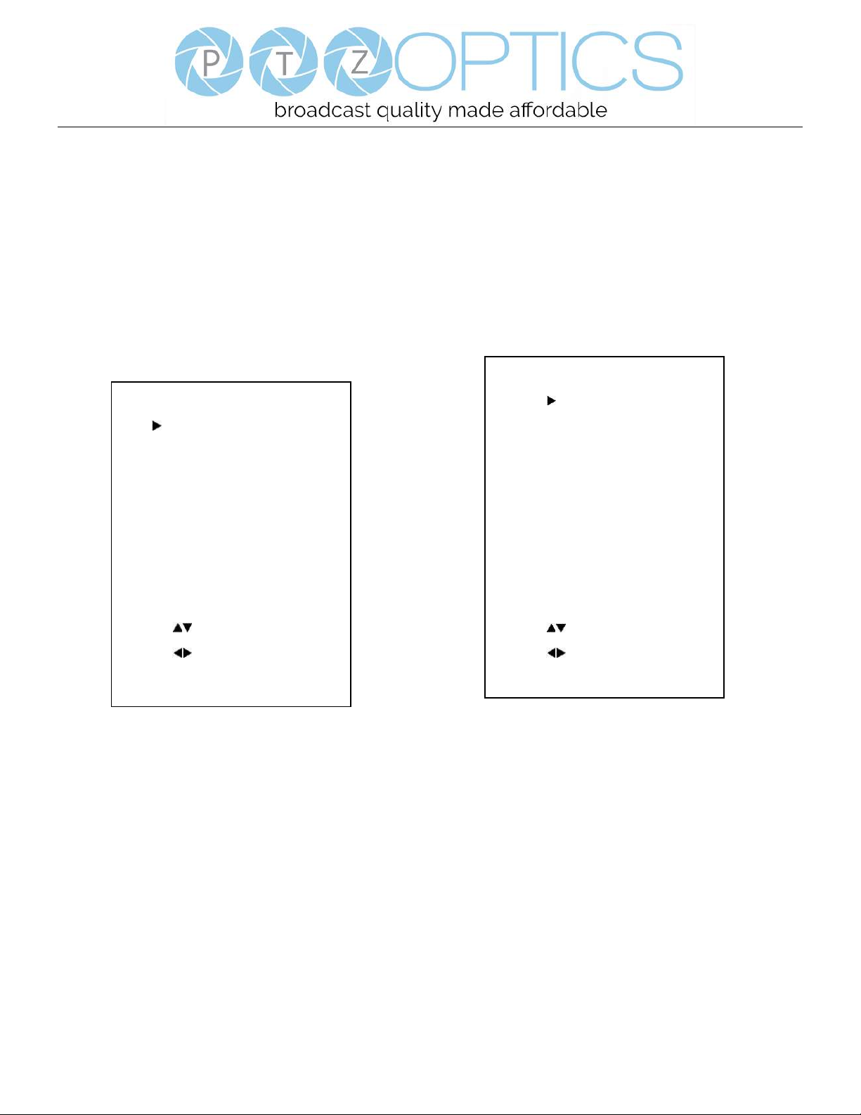
3. COLOR
Move the main menu cursor to [COLOR], and press
[HOME] key enter the color page, as shown in the
following figure.
WB-Mode: White balance mode. optional items: Auto,
Indoor, Outdoor, One Push, Manual, VAR.
RG: Red gain, optional items: 0~255 (Effective only in
Manual mode).
BG: Blue gain, optional items: 0~255 (Effective only in
Manual mode).
colortemp: Optional items: 2500K ~ 8000K (Effective
only in VAR mode).
RG Tuning: Red gain fine-tuning, optional items: -10 ~
+10 (Effective only in AWB sens is Low).
BG Tuning: Blue gain fine-tuning, optional items: -10 ~
+10 (Effective only in AWB sens is Low).
Saturation: optional items: 60% ~ 200%.
Hue: Chroma adjustment, optional items: 0 ~ 14.
AWB Sens: The white balance sensitivity, optional items:
Low, Normal, High.
4. IMAGE
Move the cursor to the Image item in the main menu and
press [HOME] button, IMAGE menu appears, as shown
in the following figure.
Luminance: Brightness adjustment, optional items:
0 ~ 14.
Contrast: Contrast adjustment, optional items: 0 ~ 14.
Sharpness: Sharpness adjustment, optional items:
Auto, 0 ~ 15.
Flip-H: Image flipped horizontally, optional items: On,
Off.
Flip-V: Image Flip Vertical, optional items: On, Off.
B&W Mode: Optional items: On, Off.
Gamma: Optional items: Default, 0.45, 0.5, 0.56, 0.63.
Style: Optional items: Norm, Clarity, Clarity (LED),
Bright, Soft, 5S.
LDC: Optional items: Off, On.
IMAGE
Luminance 7
Contrast 10
Sharpness 3
Flip-H Off
Flip-V Off
B&W-Mode Off
Gamma Default
Style Clarity
LDC Off
Select Item
Change Value
[Menu] Back
COLOR
WB Mode Auto
RG Tuning 0
BG Tuning 0
Saturation 100%
Hue 7
AWB Sens Low
Select Item
Change Value
[Menu] Back
Page 32
Page 29 of 46
Rev 1.2 5/18
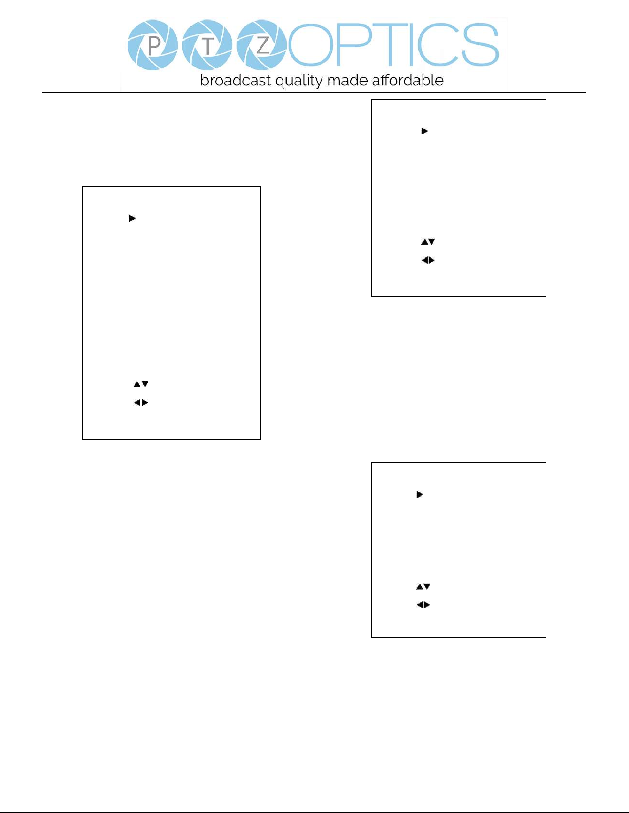
5. P/T/Z
Move the main menu cursor to [P/T/Z], and press [HOME]
key enter the P/T/Z page, as shown in the following
figure.
SpeedByZoom: The depth of field scale switch, optional
items: On, Off.
AF-Zone: Interested in focusing area, optional items: Top,
Center, Bottom.
AF-Sense: Automatic focusing sensitivity options,
optional items: Low, Normal, High.
L/R Set: Optional items: STD, REV.
Display Info: Optional items: On, Off.
Image Freeze: Optional items: On, Off.
Digital Zoom: Optional items: Off, 2x, 4x, 8x, 16x.
Call Preset Speed: Optional items: 1 ~ 24.
Pre Zoom Speed: Optional items: 0 ~ 7.
6. NOISE REDUCTION
Move the main menu cursor to [NOISE REDUCTION],
and press [HOME] key enter the noise reduction page, as
shown in the following figure.
NR2D Level: 2D noise reduction, optional items: Off,
Auto, 1 ~ 5.
NR3D Level: 3D noise reduction, optional items: Off,
1 ~ 8.
7. SETUP
Move the main menu cursor to [SETUP], and press
[HOME] key enter the setup page, as shown in the
following figure.
Language: Optional items: EN, Chinese, Russian.
DVI Mode: Optional items: DVI, HDMI.
Lens: Optional items: Type1, Type2.
auto scan shoot: Optional items: On, Off.
SETUP
Language EN
DVI Mode HDMI
Lens Type 2
auto scan shoot Off
Select Item
Change Value
[Menu] Back
NOISE REDUCTION
NR2D-Level 3
NR3D-Level 3
Select Item
Change Value
[Menu] Back
P/T/Z
SpeedByZoom On
AF-Zone Center
AF-Sense High
L/R Set STD
Display Info On
Image Freeze Off
Digital Zoom Off
Call Preset Speed 24
Pre Zoom Speed 5
Select Item
Change Value
[Menu] Back
Page 33
Page 30 of 46
Rev 1.2 5/18
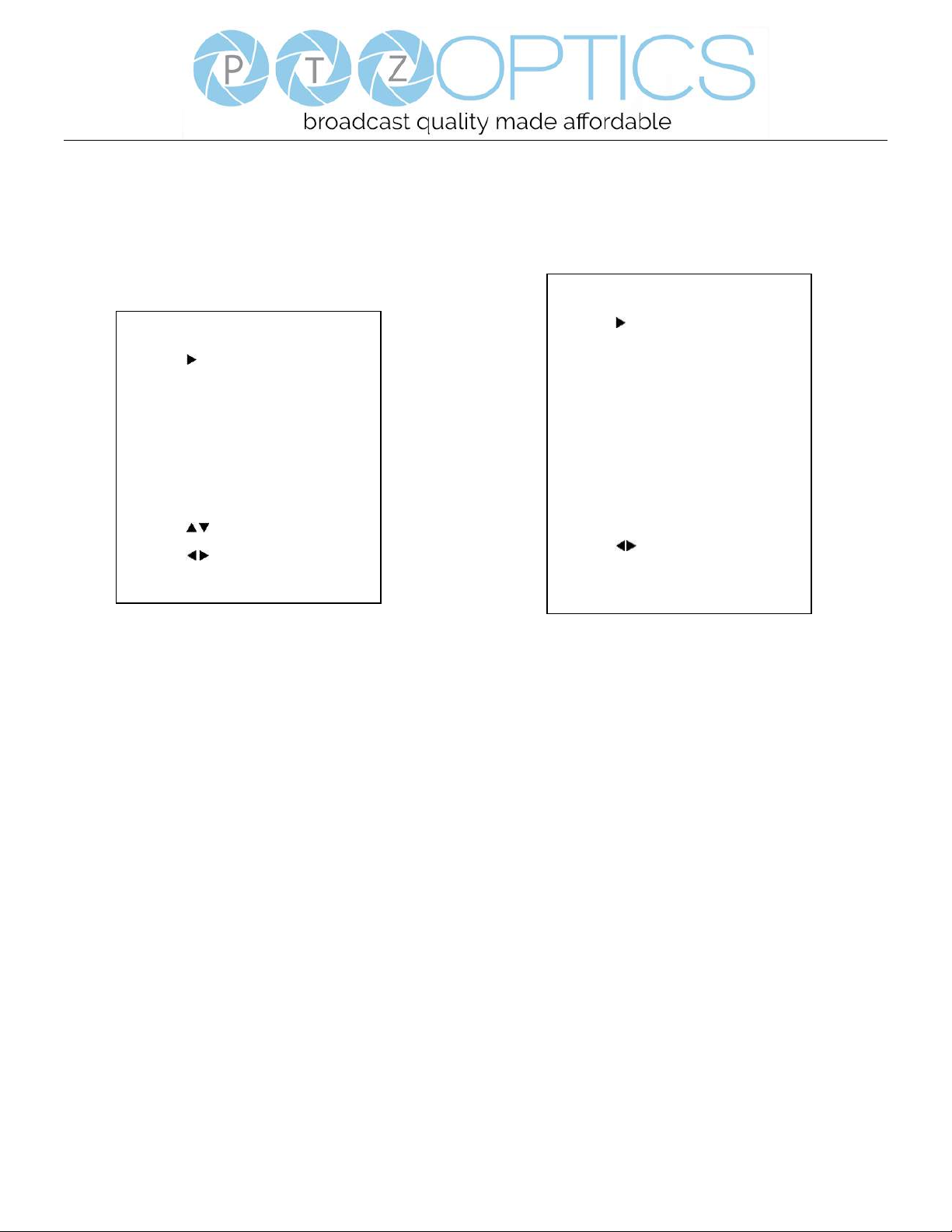
8. COMMUNICATION SETUP
Move the main menu cursor to
[COMMUNICATION SETUP], and press [HOME] key
enter the communication setup page, as shown in the
following figure.
Protocol: Control protocol type, optional items: AUTO,
VISCA, PELCO-D, PELCO-P.
V_Address: Optional items: 1 ~ 7.
P_D_Address: Optional items: 0 ~ 254. (Effective only
in PELCO-D protocol).
P_P_Address: Optional items: 0 ~ 31. (Effective only in
PELCO-P protocol).
V_AddrFix: If you can change through the serial port of
infrared switch, optional items: On, Off (When set to On,
useless in 88 30 01 FF Command).
Net Mode: Set the serial port control networking,
optional items: Serial, Paral.
Baudrate: Serial port baud rate, optional items: 2400,
4800, 9600, 38400.
9. RESTORE DEFAULT
Move the main menu cursor to [RESTORE DEFAULT],
and press [HOME] key enter the restore default page, as
shown in the following figure.
Restore: Confirm restore factory settings, optional items:
Yes, No.
Note: Press [HOME] button to confirm, all parameter
restore default, include IR Remote address and VISICA
address.
COMMUNICATION SETUP
Protocol VISCA
V_Address 1
V_AddrFix Off
Net Mode Serial
Baudrate 9600
Select Item
Change Value
[Menu] Back
RESTORE DEFAULT
Restore? No
Change Value
[Home] OK
[Menu] Back
Page 34
Page 31 of 46
Rev 1.2 5/18
Network Connection
1. Operating Environment
Operating System: Windows 2000/2003/XP/Vista/7/8.1/10
Network Protocol: TCP/IP
Client PC: P4/128M RAM/40GHD/ support for scaled graphics card, support for DirectX8.0 or more advanced version.
2. Equipment Installation
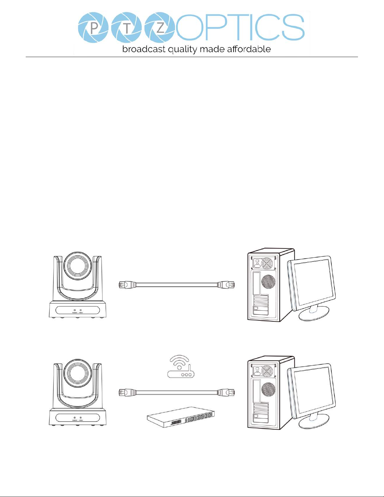
1) Connect camera to your network via a CAT5 or CAT6 patch cable or directly to your PC via a CAT5 or CAT6 cross over
cable.
2) Turn on camera power.
3) If successful, the orange network light will illuminate and the green light will start flashing. If unsuccessful, the patch
cable is bad, you are using the wrong cable (patch aka “straight-thru” cable for connection through a LAN; crossover for a
direct PC connection) or you have connected to an inactive network jack.
3. Network Connection
Connection method between network camera and computer, as in pictures 1.1 and 1.2, below:
Picture 1.1 Direct connections via “cross-over” network cable
Picture 1.2 Connections to LAN via patch cable to LAN wall jack or LAN switch
Page 35
Page 32 of 46
Rev 1.2 5/18
Setting up a Network Video Stream with the PTZ Optics Camera
(Also see information on “Camera Web Interface” in the following section)
1. The first thing you are going to want to do to get your camera up and streaming on your network is to connect your
camera to power, to an active network port on your network and finally to power the camera on.
2. Next, go online and download the IP address setting tool, for Windows Operating Systems, from the PTZOptics
Download Page.
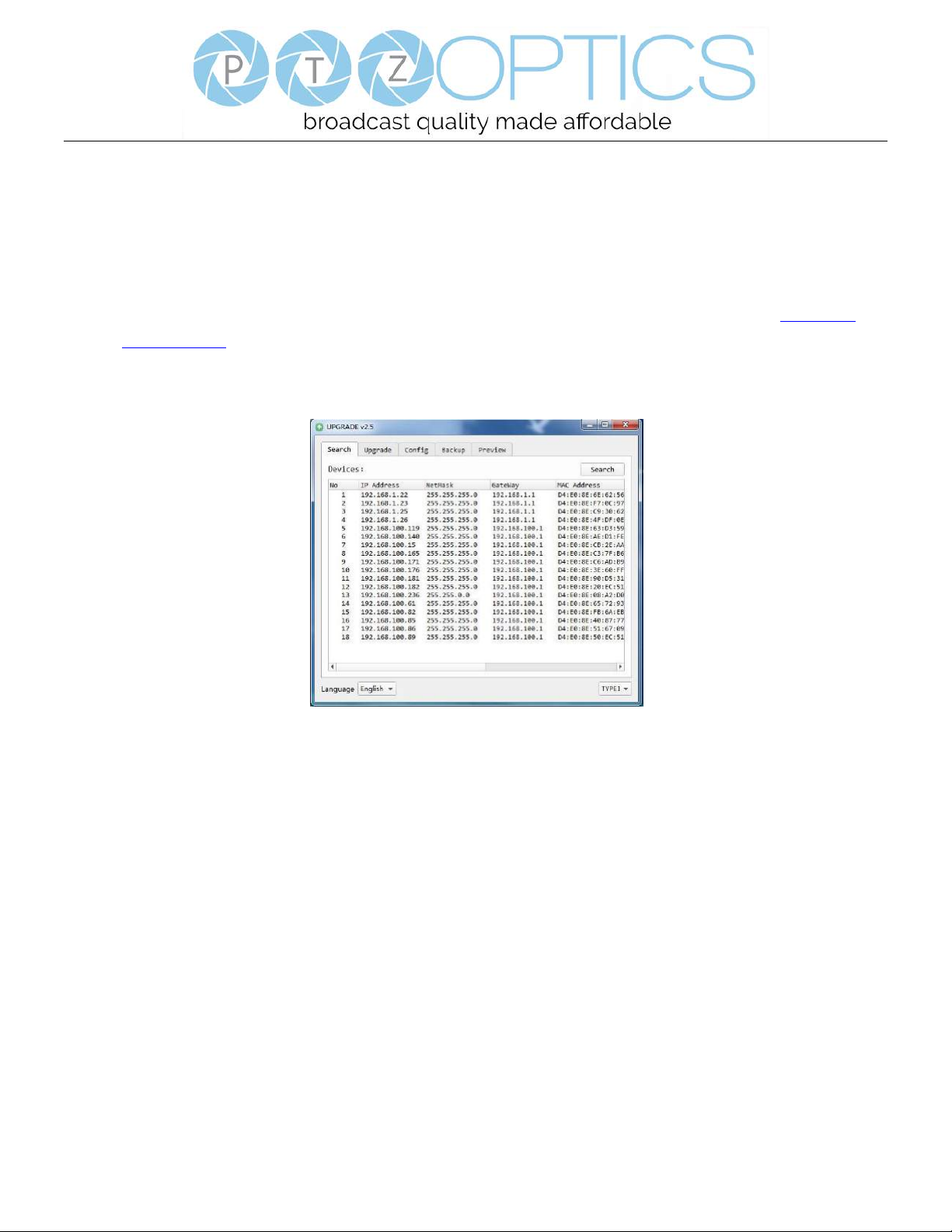
3. Once you complete the installation and launch the tool “UPGRADE v2.6C” you should be able to click the “Search”
button to locate all of the available PTZ Optics cameras on your network.
4. The next thing you would want to do is change your cameras IP address to be in the same range as your network.
The camera comes with a default static IP address of 192.168.100.88. You will need to update that to be in the same
range as your network. If you look at my example above, you can see, from other cameras on my network, that my
network is set up to be in the range of 192.168.111.XXX. Please see the “Extras” information at the end of this
section for further information on identifying your network IP scheme
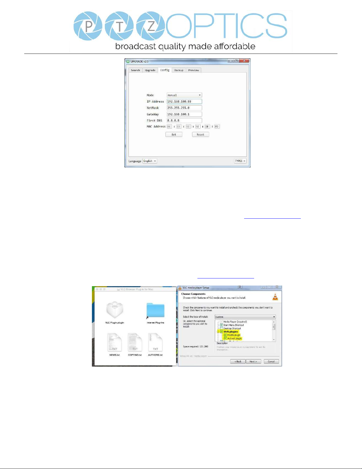
5. Once you know your IP range you can right click on the camera you wish to change the IP address for and select
“config” to enter the appropriate network information. NOTE: if you need to find the IP range of your network, you
can do so by following the guide in the “Extras” information at the end of this section.
Page 36
Page 33 of 46
Rev 1.2 5/18
(Note that in more complex network environments you may have to request a “Static IP” from the IT department to prevent
any possible network complications in addition to the “Static IP” you will likely need an appropriate Network Mask, Default
Gateway and First DNS)
6. Now that you have set the Static IP address of your PTZ Optics camera, you should be able to pull up the video feed
in a web browser. We recommend using Mozilla Firefox ESR. You can view our knowledge base article for detailed
setup instructions.
7. If you follow the steps in the knowledge base article above and type in the Static IP address you assigned to your
camera, in step 4, you will be prompted for a Username and Password, by default both are “admin”.
8. You may be prompted to download the VLC Player Plugin; be sure to allow for both the Mozilla plugin and the
ActiveX plugin if on a PC. If you are on a MAC, you need to move the VLC plugin, once downloaded, into the
internet plugins folder. See the images below, or refer to our knowledge base article, for further clarification.
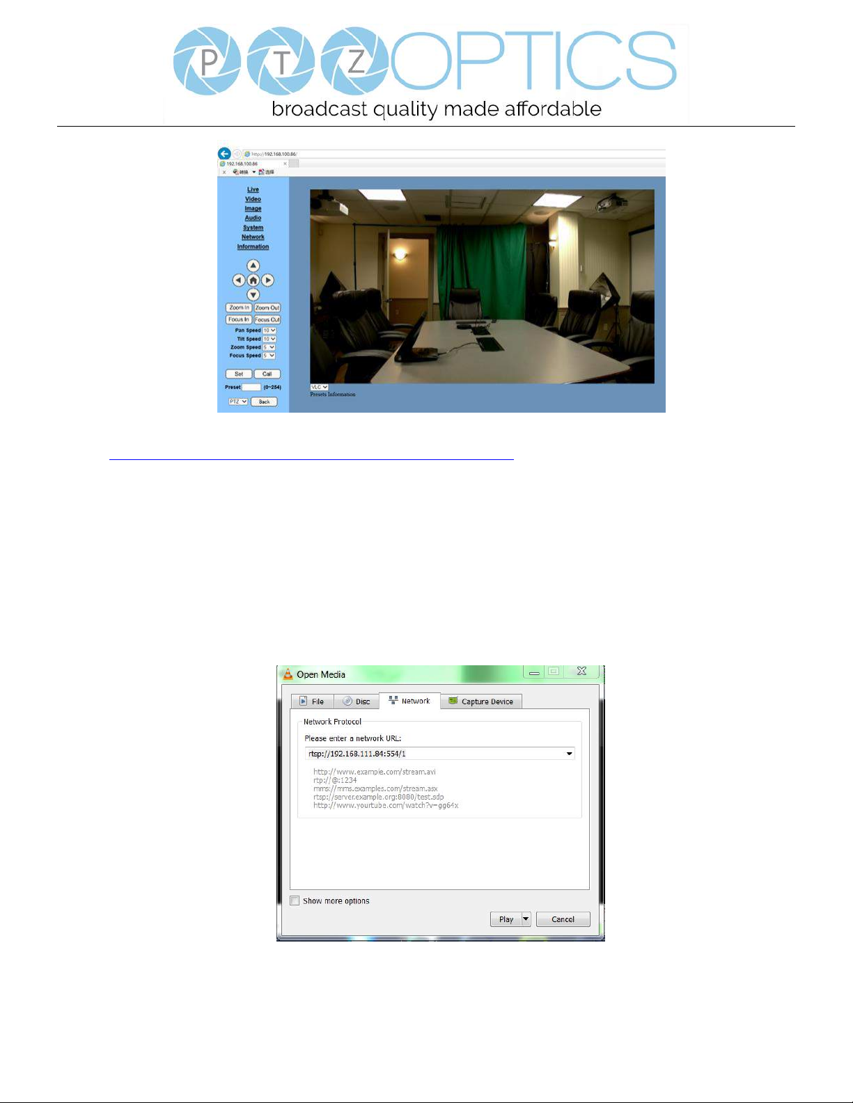
9. You should now be able to see the IP interface in the browser of your live camera feed. You should have full P/T/Z
control over your camera using the P/T/Z controls on the left side. You can adjust many of your cameras settings via
this IP interface.
The main thing to note about the IP interface is that all presets set in the IP interface will not be the same as the IR
remote presets and vice-versa.
Page 37
Page 34 of 46
Rev 1.2 5/18
10. You should now be able to receive an RTSP stream from your camera. The following video,
https://www.youtube.com/watch?v=hmqI0hjT0UI&feature=youtu.be, shows how to setup an RTSP stream in
Wirecast as an example. You’ll see how to use ONVIF to easily set up two (2) PTZ Optics cameras with Wirecast,
note that the ONVIF feature must be enabled in the “Network” settings for ONVIF discovery to work properly.
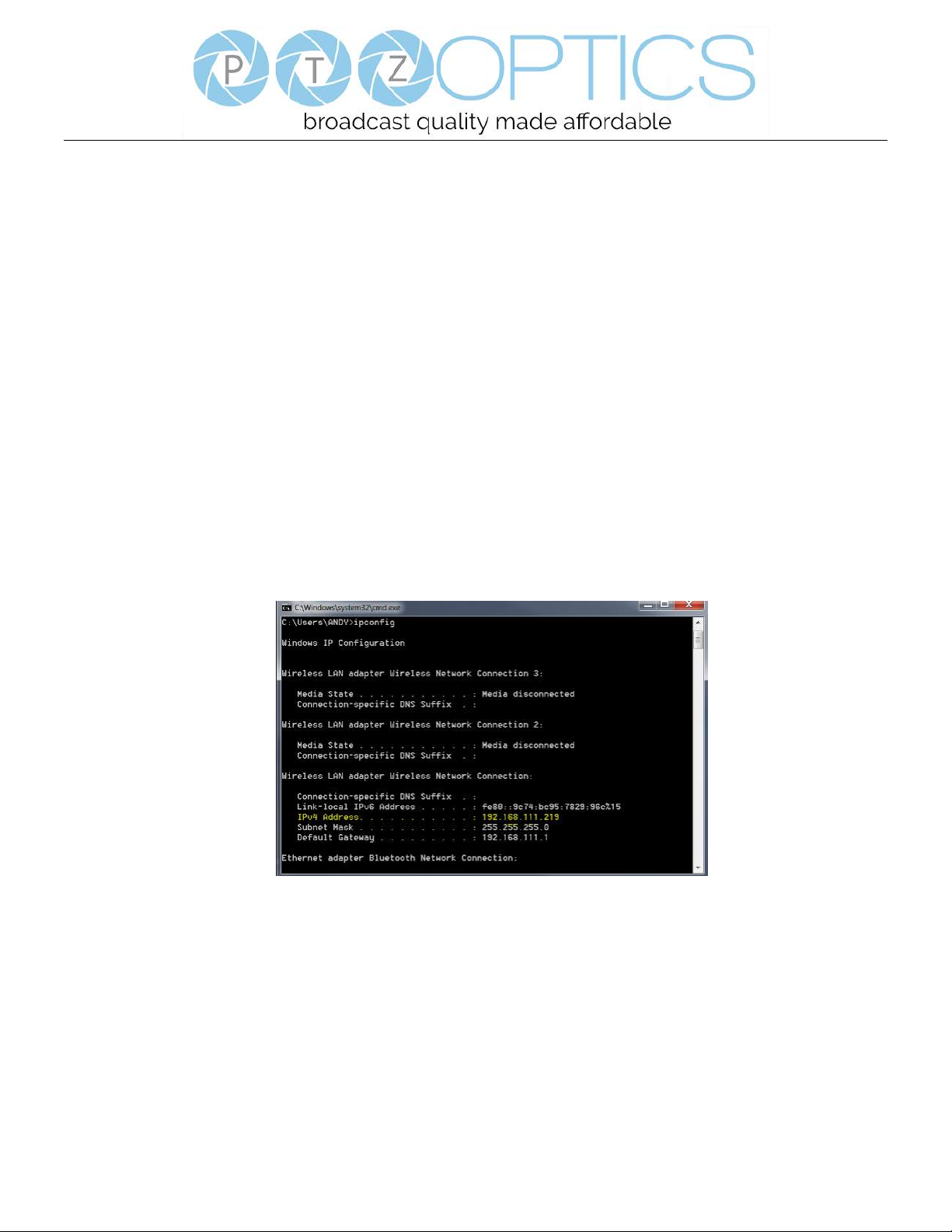
11. You can test the RTSP stream in VLC media player. Once you install VLC and launch the program you should be
able to go to the “Media” drop down menu and then select “Open Network Stream”. In the network URL, you
should enter “rtsp://<camera-ip-address>:554/1”. In the example below, for a PTZ Optics camera with the static IP
address of 192.168.111.84, the RTSP stream would accessed by entering rtsp://192.168.111.84:554/1. The “554”
part is the port number used by the cameras, and the “1” is the stream number. (There are two RTSP network
streams available; one for HD content “1” and one for SD content “2”).
Page 38
Page 35 of 46
Rev 1.2 5/18
EXTRAS
Discovering your Network IP range. NOTE: Changing your IP address without talking to your network admin
could lead to conflicts with your network. If you change your address to one that is already in use it will cause
communication problems.
If you need to discover the IP address range of your network you can do so by using command prompt for
Windows or Terminal for Macs.
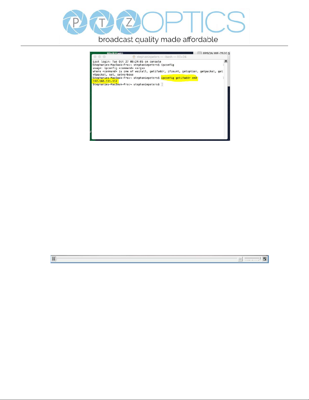
To do this on a PC, you would type “CMD” into your search bar in the Windows menu. You should see a
black box pop up with the ability to type in the box.
If you type “ipconfig” and hit “Enter” on your keyboard you will see a bunch of information pop up in your
command prompt.
When you see “IPV4 Address” that is your computers IP address on your current network. So you would use the first 3
sets of numbers from this as your IP range.
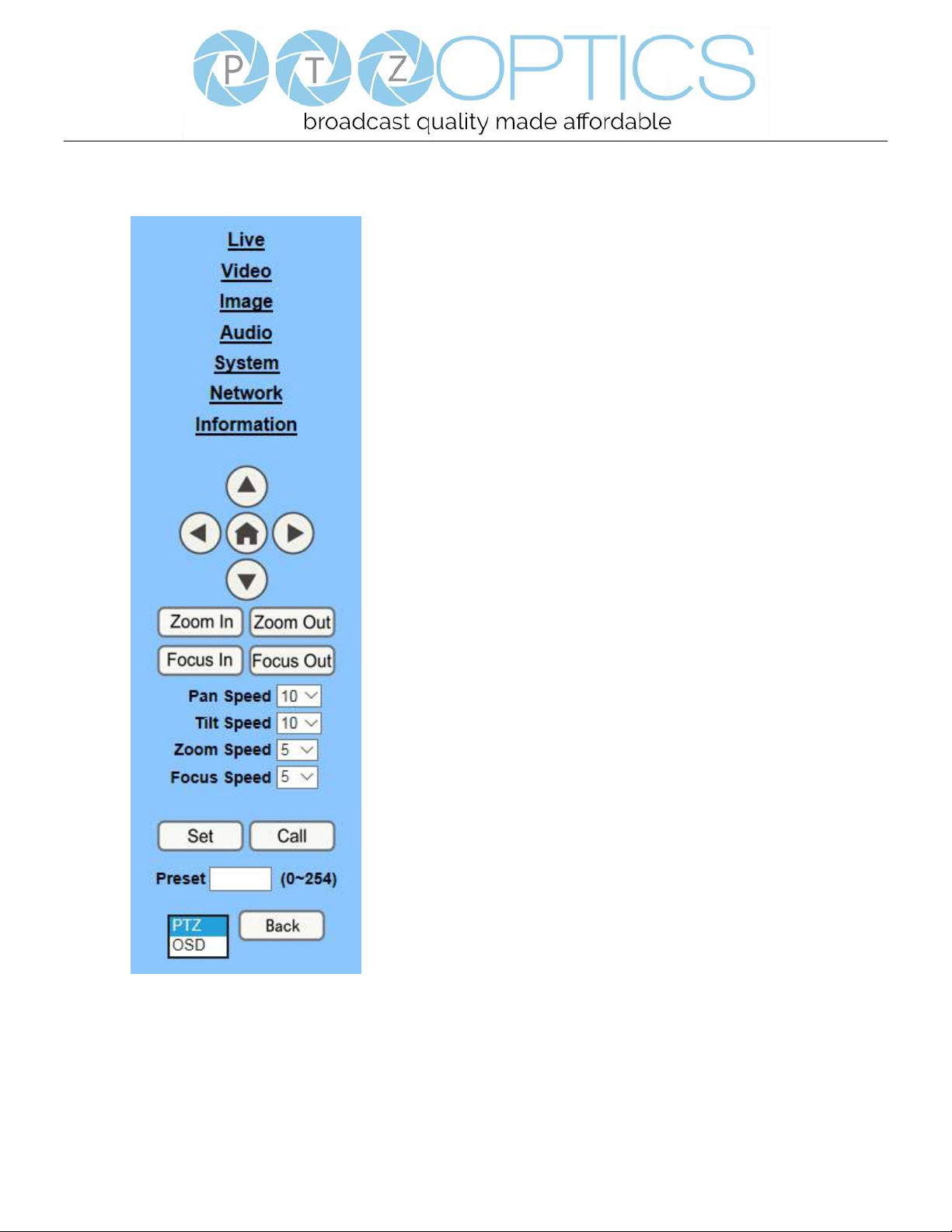
If you need to find the IP range of your MAC computer, you would first open a new finder window and then
go to Applications, and then Utilities. You should see the program “Terminal” in that menu, select that program.
Now, you would type in “IP config get if addr en0” Once you type this string and click “Enter” on your
keyboard you will receive back an IP address.
So the IP range of my network, according to my MAC is 192.168.111.xxx, you can use this to figure out the
IP range in which your camera needs to be set.
Page 39
Page 36 of 46
Rev 1.2 5/18
Camera Web Interface
1 Homepage introduction
1.1 Home Page
All pages include two (2) areas:
On the left is the menu and camera control
On the right is real time monitoring - displaying a live video image and the available settings
1.2 Live Video viewing window
Click “Live” in the menu area. The video viewing window will be resized based upon video resolution, the higher
the resolution is, the bigger the playing area is. Double click the viewing window and it will show in full-screen.
Double click again, and it will return to the initial size.
The Status bar in the viewing window is as shown below:
1)Video playback/pause button: controls real-time video. Pause to freeze the image, play to return to live video.
2)Audio control buttons: Mute and Volume controls for audio input on camera, if being used.
3)Full screen button will switch between Full Screen and Windowed view.
Page 40
Page 37 of 46
Rev 1.2 5/18
1.3 PTZ Control
1) Pan and Tilt control: Up, Down, Left and Right arrows and the
home button allow you to manually drive the camera to the desired
position.
2) Zoom: Zoom In and Zoom Out buttons allow for wide or
narrow (tele) view of the space.
3) Focus: Focus In and Focus Out buttons allow for fine manual
focus adjustment if the camera has any problems auto focusing on
a difficult object.
4) PTZ Speeds: Pan speed can be set at any rate between 1 - 24,
Tilt speed can be set at any rate between 1 - 20.
Zoom and Focus speeds can be set at any rate between 0 – 7.
5) PTZ Presets: After manually setting up a shot that you would
like to return to later, you can save presets for quick recall of these
positions. Type a number between 0 and 254 into the Preset box.
Click the "Set" button to save the current location with that preset
number. Click the “Call” button to cause the camera to return to
that position. This enables smooth, quick and convenient control
without the need to manually drive the camera.
6) PTZ/OSD dropdown: From the dropdown menu, clicking the
OSD option will open the on-screen display menu of the camera
giving you control from within the IP interface.
Page 41
Page 38 of 46
Rev 1.2 5/18
1.4 Language selection
Click either “Russian”, “Chinese” or “English” to change the language of the menu.
1 Media
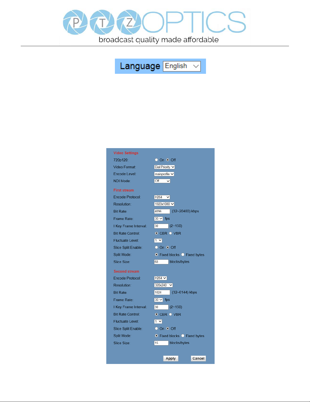
1.1 Video Setup
Click "Video". The streaming parameters may now be set in the right side area. The camera can send two (2)
simultaneous streams. For example, you can send one stream in HD and one in SD so that both PCs and phones
may have their own compatible stream resolution.
Page 42

Page 39 of 46
Rev 1.2 5/18
1) 720p120
Turn On/Off 720p120 function.
2) Video Format
Support 50HZ (PAL) and 60HZ (NTSC), and Dial Priority three formats.
3) Encode Level
Support baseline, mainprofile, highprofile and svc-t four levels.
4) NDI Mode
Support Off, High, Medium and Low four mode.
5) Encode Protocol
Support H.264, H.265 and MJPEG three formats.
6) Resolution
First stream support 1920x1080, 1280x720, 1024x576, 960x540, 640x480, 640x360, second stream support
1280x720, 1024x576, 720x576, 720x408, 640x360, 480x270, 320x240, 320x180, the bigger resolution is, the
clearer the image will be, more network bandwidth will be taken.
7) Bit Rate
User can assign bit flow/stream, normally speaking, the bigger bit flow is, the clearer the image will be. The
bit allocation must combine with network bandwidth, when the network bandwidth is too narrow and the
allocated bit flow is too big, will cause video signal flow not to be transmitted normally, the video effect will
be worse.
8) Frame Rate
User can specify the size of the frame rate, generally, the frame rate greater, the image more smooth; Frame
rate is smaller, the more sense of beating.
9) I Key Frame Interval
Set interval between 2 I frame, the bigger interval is the response will be lower from viewing window.
10) Bit Rate Control
Code stream control way:
Constant bit rate: video coder will be coding according to preset speed.
Variable bit rate: video coder will adjust the speed based on preset speed to gain the best image quality.
11) Fluctuate Level
Restrain the fluctuation magnitude of variable rate, grade 1 ~ 6.
12) Slice Split Enable
Enable or disable slice split function.
Page 43
Page 40 of 46
Rev 1.2 5/18
13) Split Mode
Select split mode, optional items: Fixed blocks, Fixed bytes.
14) Slice Size
Set the size of slice.
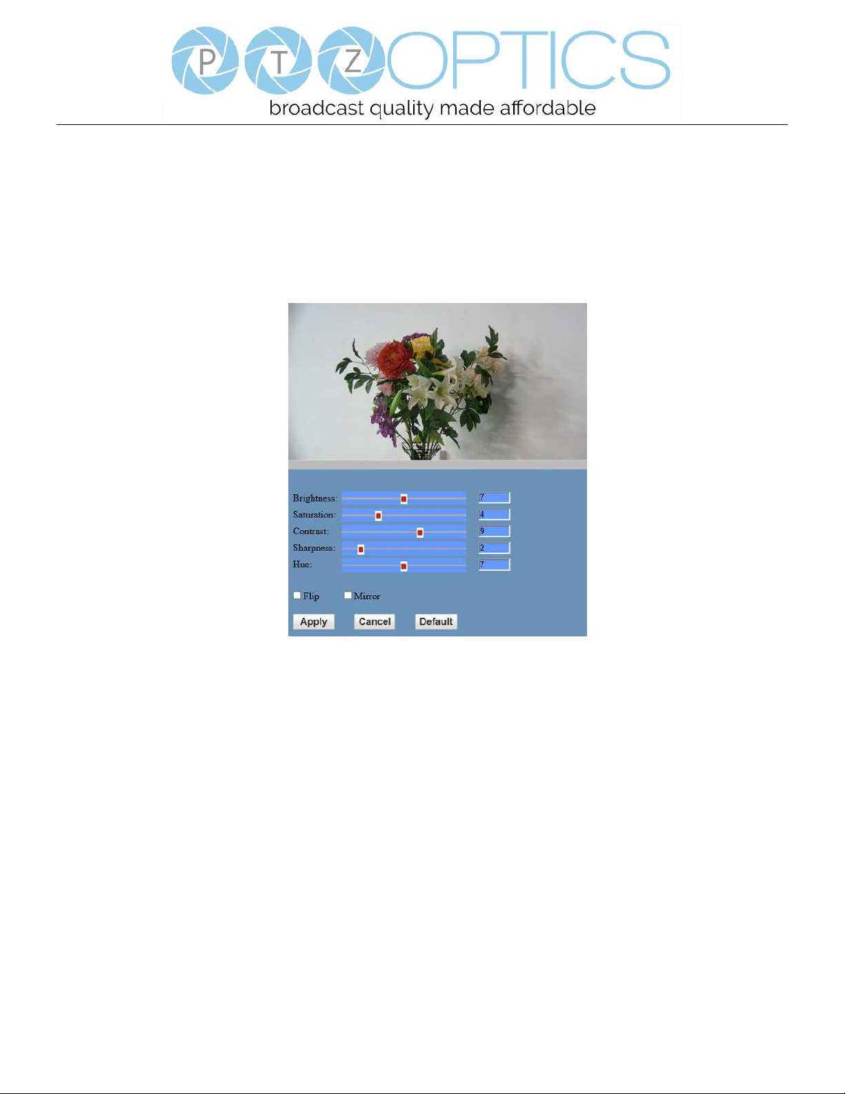
1.2 Image Setup (Note that changes here will impact your OSD settings)
Click “Image”. The image parameters may now be set in the right-side area.
1) Brightness
Image bright 0~14, slider control, on the right shows the corresponding numerical. Default value is 7.
2) Saturation
Saturation 0~14, slider control, on the right shows the corresponding numerical. Default value is 4.
3) Contrast
Contrast 0~14, slider control, on the right shows the corresponding numerical. Default value is 9.
4) Sharpness
Sharpness 0~15, slider control, on the right shows the corresponding numerical. Default value is 2.
5) Hue
Hue 0~14, slider control, on the right shows the corresponding numerical. Default value is 7.
6) Flip & Mirror
Tick Flip to realize image upside down, tick mirror to realize image around the mirror.
Default value is not tick.
Page 44
Page 41 of 46
Rev 1.2 5/18
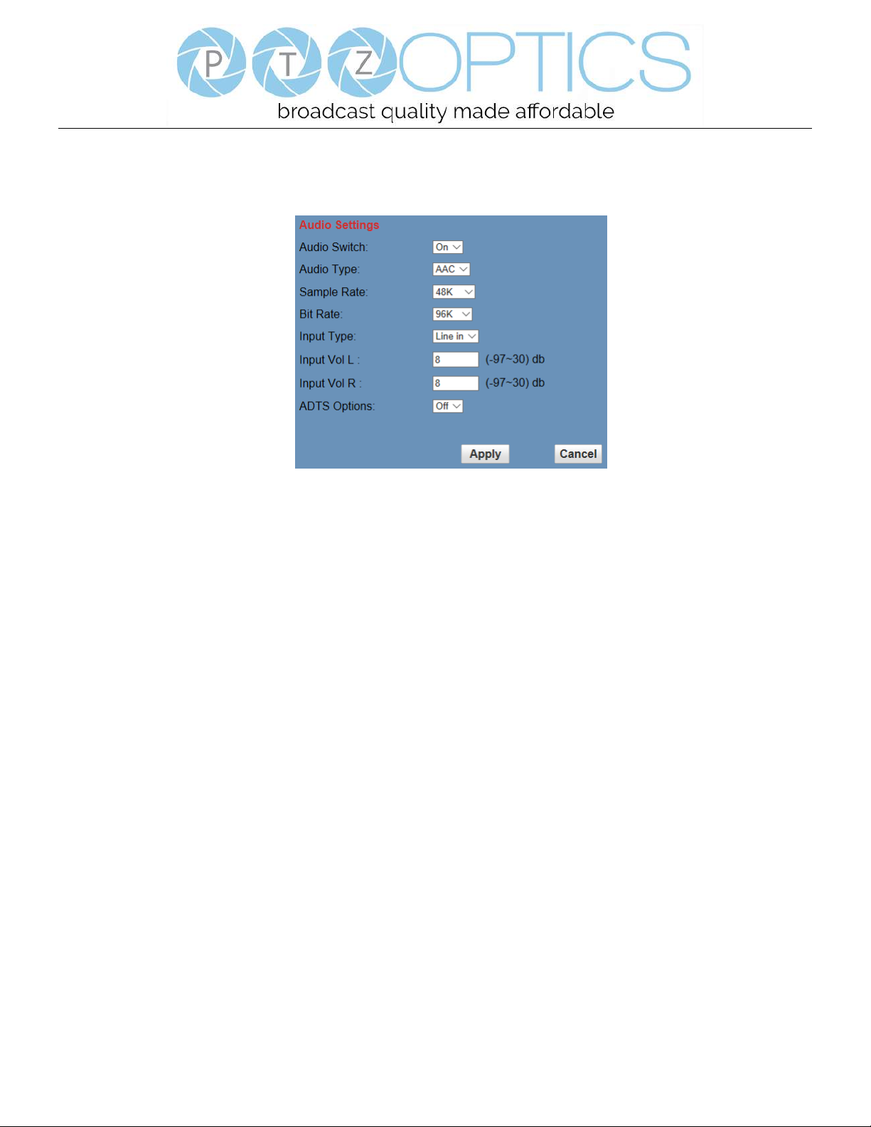
1.3 Audio Setup
Click “Audio”. The audio parameters may now be set in the right-side area.
1) Audio Switch
Turn On/Off audio switch.
2) Audio Type
Audio type AAC.
3) Sample Rate
Sample rate 44.1 K and 48 K selectable.
4) Bit Rate
Bit rate 96k, 128k, 256k selectable.
5) Input Type
Input type line in.
6) Input VolL
The volume of the left channel.
7) Input VolR
The volume of the right channel.
8) ADTS Options
Optional items: On, Off.
Page 45
Page 42 of 46
Rev 1.2 5/18
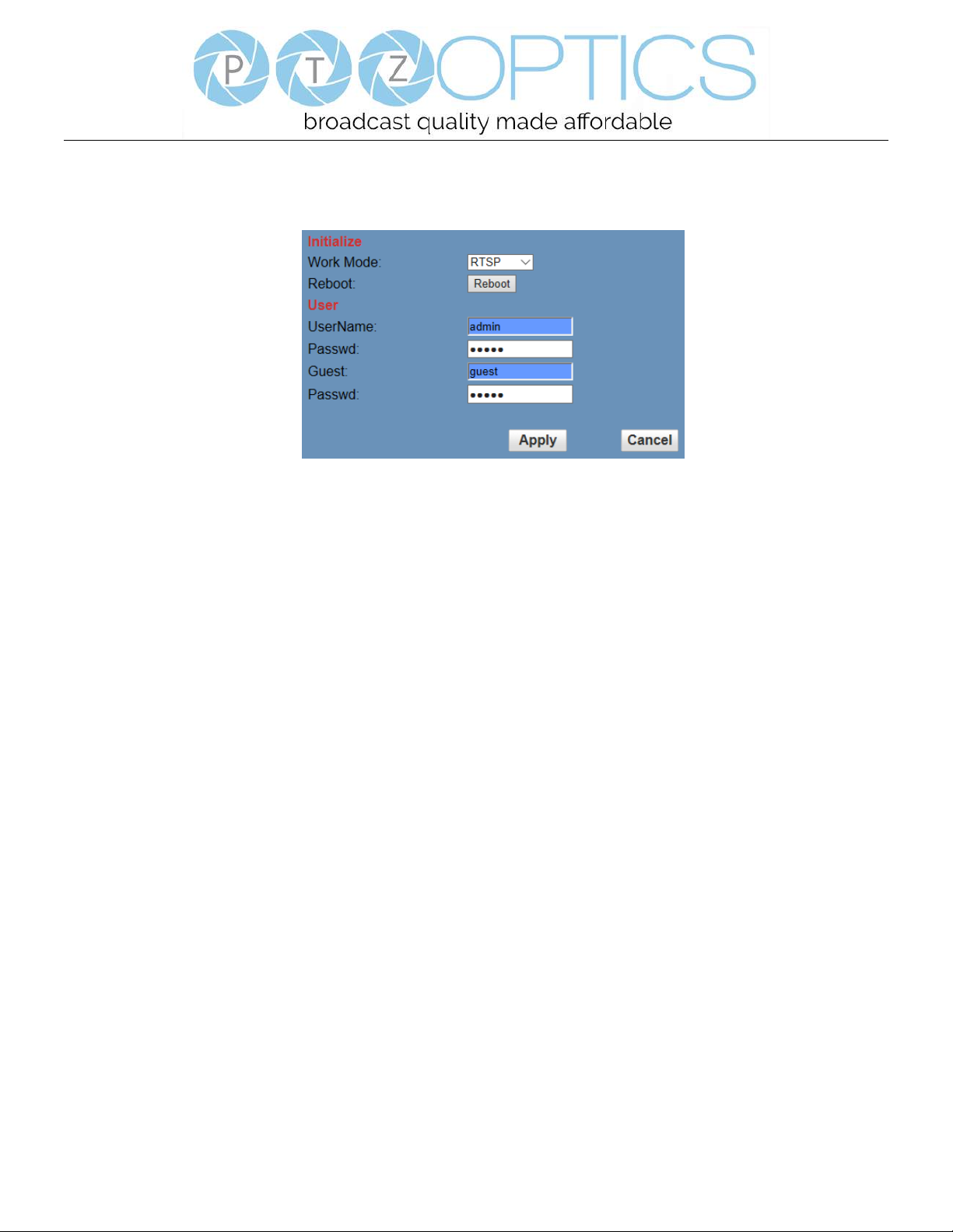
1.4 System Settings
Click “System”. The system parameters may now be set in the right-side area.
1) Work Mode
Work Mode is RTSP.
2) Reboot
Click the “Reboot” button, system restart.
3) Username and password
The user can modify the password (letters and numbers only).
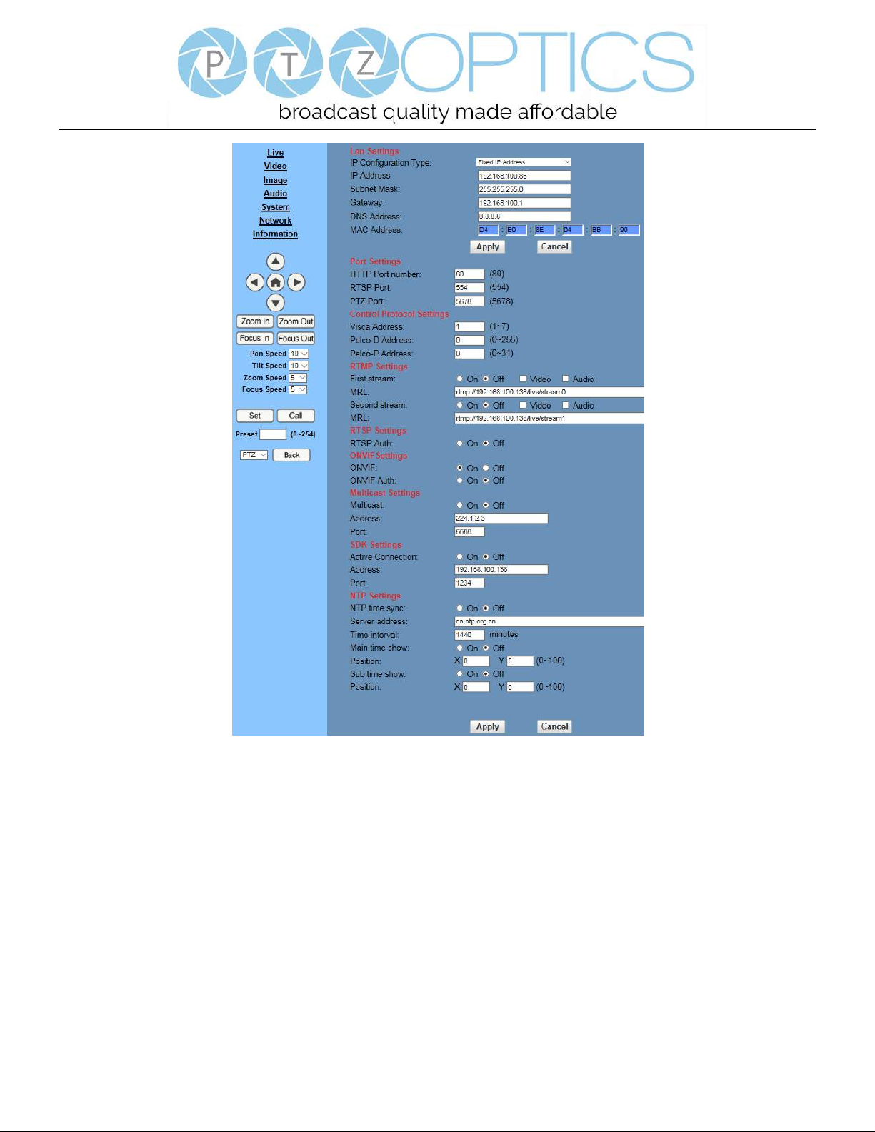
1.5 Network Settings
Click “Network”. The network parameters may now be set in the right side area.
Page 46
Page 43 of 46
Rev 1.2 5/18
1) Lan Settings
Default the IP address is 192.168.100.88. The MAC address can not be modified.
2) Port Settings
While the IP address identifies the device, the camera uses multiple ports for different functions.
HTTP Port: This is the port for the web application (the default http port: 80)
RTSP Port: The camera supports the RTSP streaming protocol. The default port: 554.
PTZ Port: Supports camera control via the TCP protocol. The default port: 5678.
3) Control Protocol Settings
Setting camera control communication protocol, include Visca address, Pelco-D address and Pelco-P address.
Page 47
Page 44 of 46
Rev 1.2 5/18
4) RTMP Settings
Setting the camera stream, can set up two stream, in the two stream selection control code stream of “On”,
“Off”, “Video”, “Audio”, etc.
5) RTSP Settings
Turn On/Off RTSP auth.
6) ONVIF Settings
Turn On/Off ONVIF and ONVIF auth.
7) Multicast Settings
Turn On/Off multicast. Setting multicast address (default value is 224.1.2.3) and port (default value is 6688).
8) SDK Settings
Turn On/Off active connection. Setting SDK address (default value is 192.168.100.138) and port (default
value is 1234).
9) NTP Settings
Turn On/Off NTP time sync, main time show and sub time show. Setting NTP server address, time interval,
main stream position and sub stream position.
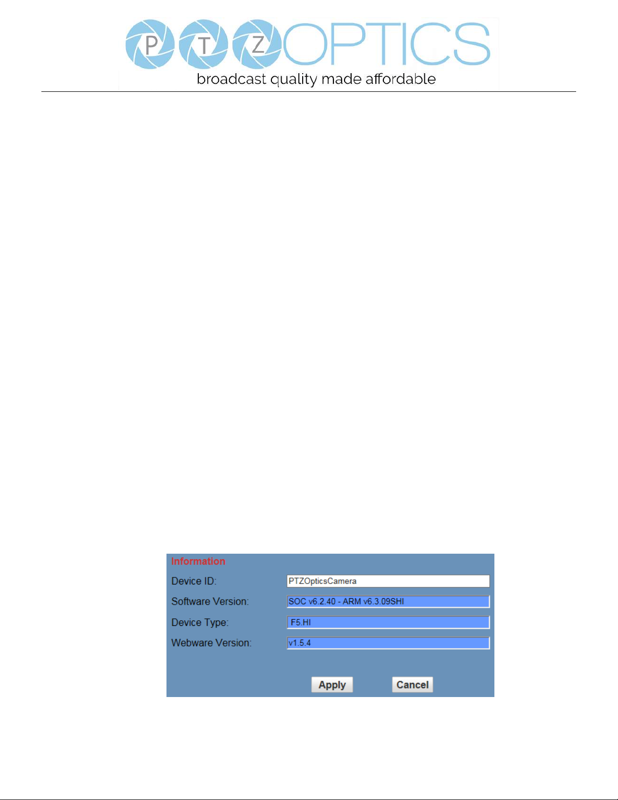
1.6 Device Information
Click “Information”
Shows the current device information, as shown below. You may change the device ID as required for your
application.
Page 48

Page 45 of 46
Rev 1.2 5/18
Maintenance and Troubleshooting
Camera Maintenance
⚫ If the camera will not be used for a long time, please turn off the power switch.
⚫ Use a soft cloth or lotion-free tissue to clean the camera body.
⚫ Use a soft dry lint-free cloth to clean the lens. If the camera is very dirty, clean it with a diluted neutral detergent.
Do not use any type of solvent or harsh detergent, which may damage the surface.
Unqualified Applications
⚫ Do not shoot extremely bright objects for a long period of time, such as sunlight, ultra-bright light sources, etc...
⚫ Do not operate in unstable lighting conditions, otherwise the image may flicker.
⚫ Do not operate close to powerful electromagnetic radiation, such as TV or radio transmitters, etc…
Troubleshooting
⚫ No image
1. Check whether the power cord is connected, voltage is OK, POWER lamp is lit.
2. Check whether the camera can “self-test” after startup (camera will do a brief pan-tilt tour and return to the
home position, or if preset 0 is set, the camera will return to the preset 0 position).
3. Check the BOTTOM dip switch and make sure the two dip switches are both set OFF. These switches are not
used in operating mode.
4. Check that the HDMI cable is connected correctly.
1. If HDMI, make sure that the destination device is accessing the HDMI port that you plugged into.
2. If SDI, make sure that the destination device is accessing the SDI port that you plugged into.
⚫ Abnormal display of image
1. Check setting of rotary dial on rear of camera. Be sure to use a resolution and refresh rate that is supported by
your software.
⚫ Image is shaky or vibrating.
1. Check whether camera is mounted solidly or sitting on a steady horizontal and level surface.
2. Check the building and any supporting furniture for vibration. Ceiling mounts are often affected by building
vibration more than wall mounts.
3. Any external vibration that is affecting the camera will be more apparent when in tele zoom (zoomed in)
settings.
Page 49

Page 46 of 46
Rev 1.2 5/18
Control
⚫ IR remote controller does not control the camera
1. Does one of the 4 “Camera Select” buttons (top row of remote) light up when you press any button on the
remote?
If not, change the batteries in the remote.
2. Are the camera and remote set to the same IR address? You can use press [*] + [#] + [1] (3 buttons in
sequence) on the remote to set the camera to address 1. Press “Camera Select” 1 on the remote to control the
camera.
3. Try removing other sources of IR interference (e.g. sunlight, fluorescent lighting).
⚫ Serial communication does not control the camera
1. Make sure the camera is on and functioning with the IR remote control.
2. Verify that the RS232 cable is connected correctly and using the proper pinout.
3. Verify the communication settings of the control software or device (e.g. joystick).
4. Verify that the communication port on the controlling device is activated (e.g. Com port on PC).
5. Verify that all communication settings in the OSD Setup Menu correlate to the commands being used (e.g.
VISCA address).
Copyright Notice
The entire contents of this manual, whose copyright belongs to PTZ Optics, may not be cloned, copied or translated
in any way without the explicit permission of the company. Product specifications and information referred to in this
document are for reference only and as such are subject to updating at any time without prior notice.
 Loading...