

PTZOptics PT20X-USB-G2 Users Manual
Please check PTZOPTICS.com for the most up to date version of this document Rev 1.2 6/18
PTZOptics 20X USB (GEN-2)
User Manual
Model Nos: PT20X-USB-GY-G2 & PT20X-USB-WH-G2
V1.2
(English)

Page i of 57
Rev 1.2 6/18
Preface
Thank you for using the USB 3.0 HD Video Conferencing Camera. This manual introduces the function, installation and
operation of the HD camera. Prior to installation and usage, please read the manual thoroughly.
Note: Minimum USB 3.0 System Requirements: i3 Quad-Core
(Recommended: i5 Quad Core or better)
Precautions
This product can only be used in the specified conditions in order to avoid any damage to the camera:
• Don’t subject the camera to rain or moisture.
• Don’t remove the cover. Removal of the cover may result in an electric shock in addition to voiding the warranty.
In case of abnormal operation, contact the manufacturer.
• Never operate outside of the specified operating temperature range, humidity, or with any other power supply
than the one originally provided with the camera.
• Please use a soft dry cloth to clean the camera. If the camera is very dirty, clean it with diluted neutral detergent;
do not use any type of solvents, which may damage the surface.
Note
This is an FCC Class A Digital device. As such, unintentional electromagnetic radiation may affect the image quality of TV in a
home environment.

Page ii of 57
Rev 1.2 6/18
Table of Contents
1 Supplied Accessories ··································································································· 1
2 Notes ······················································································································ 1
3 Quick Start ··············································································································· 2
4 Features ··················································································································· 4
5 Product Specifications ·································································································· 5
6 Main Unit ················································································································· 7
7 IR Remote Controller ··································································································· 8
8 Using the IR Remote Controller ····················································································· 10
9 Dimensional Drawings ································································································ 13
10 RS-232 Interface ······································································································· 14
11 VISCA Commands ····································································································· 16
12 VISCA over IP Commands ··························································································· 25
13 Menu Setting ············································································································ 32
14 Network Connection ··································································································· 36
15 Maintenance and Trouble Shooting ·················································································· 54
Page 1 of 57
Rev 1.2 6/18
Supplied Accessories
When you unpack your camera, check that all the supplied accessories are included:
⚫ Camera .................................. 1
⚫ AC Power Adaptor ................ 1
⚫ Power Cord ........................... 1
⚫ USB 3.0 AB Cable ................ 1
⚫ RS232 Cable ......................... 1
⚫ IR Remote Controller ........... 1
⚫ This User Manual ................. 1
Notes
⚫ Electrical Safety
Installation and operation must be in accordance with national and local electric safety standards. Do not use any power
supply other than the one originally supplied with this camera.
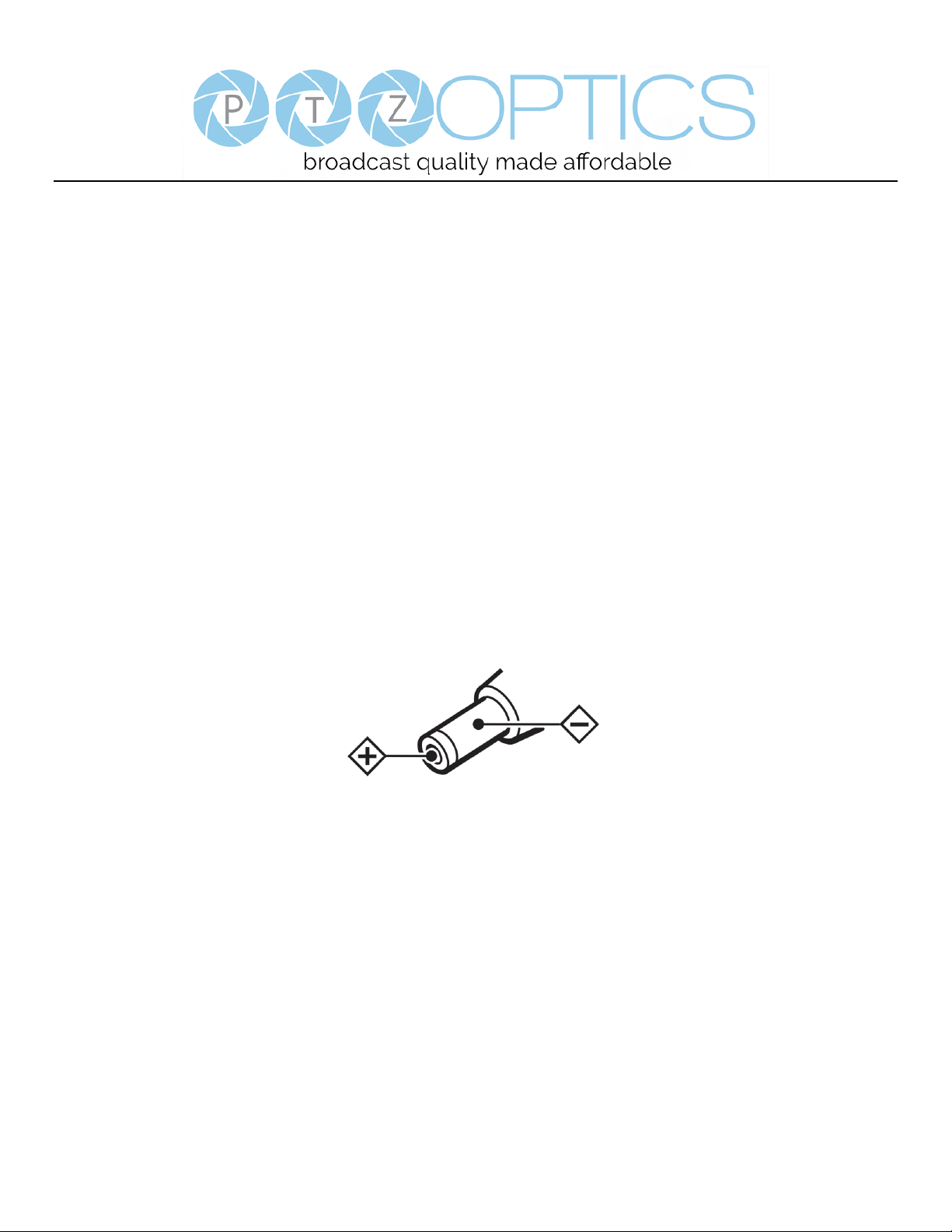
⚫ Polarity of power supply
The power supply output for this product is 12VDC with a maximum current supply of 2A. Polarity of the power supply
plug is critical and is as follows.
⚫ Handling
◼ Avoid any stress, vibration, or moisture during transportation, storage, installation and operation.
◼ Do not lift or move the camera by grasping the camera head. Do not turn the camera head by hand. Doing so may
result in mechanical damage.
◼ Do not expose camera to any corrosive solid, liquid, or gas to avoid damage to the cover which is made of a plastic
material.
◼ Ensure that there are no obstacles in the tilt or pan ranges of the camera lens.
◼ Never power camera on before installation is complete.
⚫ Do not dismantle the camera - The manufacturer is not responsible for any unauthorized modification or dismantling.
Page 2 of 57
Rev 1.2 6/18
Quick Start
Step 1. Please check that all connections are correct before powering on the camera.
Page 3 of 57
Rev 1.2 6/18
Step 2. Set the system select (rotary) switch for your desired USB and HDMI video output resolution and frame rate.
For many applications, setting 0 (1080p-60) will provide the best overall performance.
For highest possible resolution, use setting 0 (1080p-60) or 6 (1080p-30), however your actual realized frame rate may
be limited to a lower value than 30 fps by your software and/or network connection.
NOTE: After changing this dial, you need to restart the camera to see the effect. Turn the camera off.
VIDEO SYSTEM
0
1080p60
8
720p30
1
1080p50
9
720p25
2
1080i60
A - 3
1080i50
B - 4
720p60
C - 5
720p50
D
576i
6
1080p30
E
480i
7
1080p25
F
-
CAUTION:
a. After changing the system (rotary) switch, you need to restart the camera to take effect.
Step 3. Press the Switch ON button on the rear of the camera, the power lamp will illuminate.
Step 4. The Pan-Tilt mechanism will rotate the lens to the maximum position of top right after the camera starts, then it will
return to the “center”. The process of initialization is now complete. (Note: If the position preset 0 has been stored, the position
preset 0 will be called up after initialization in lieu of “center”)
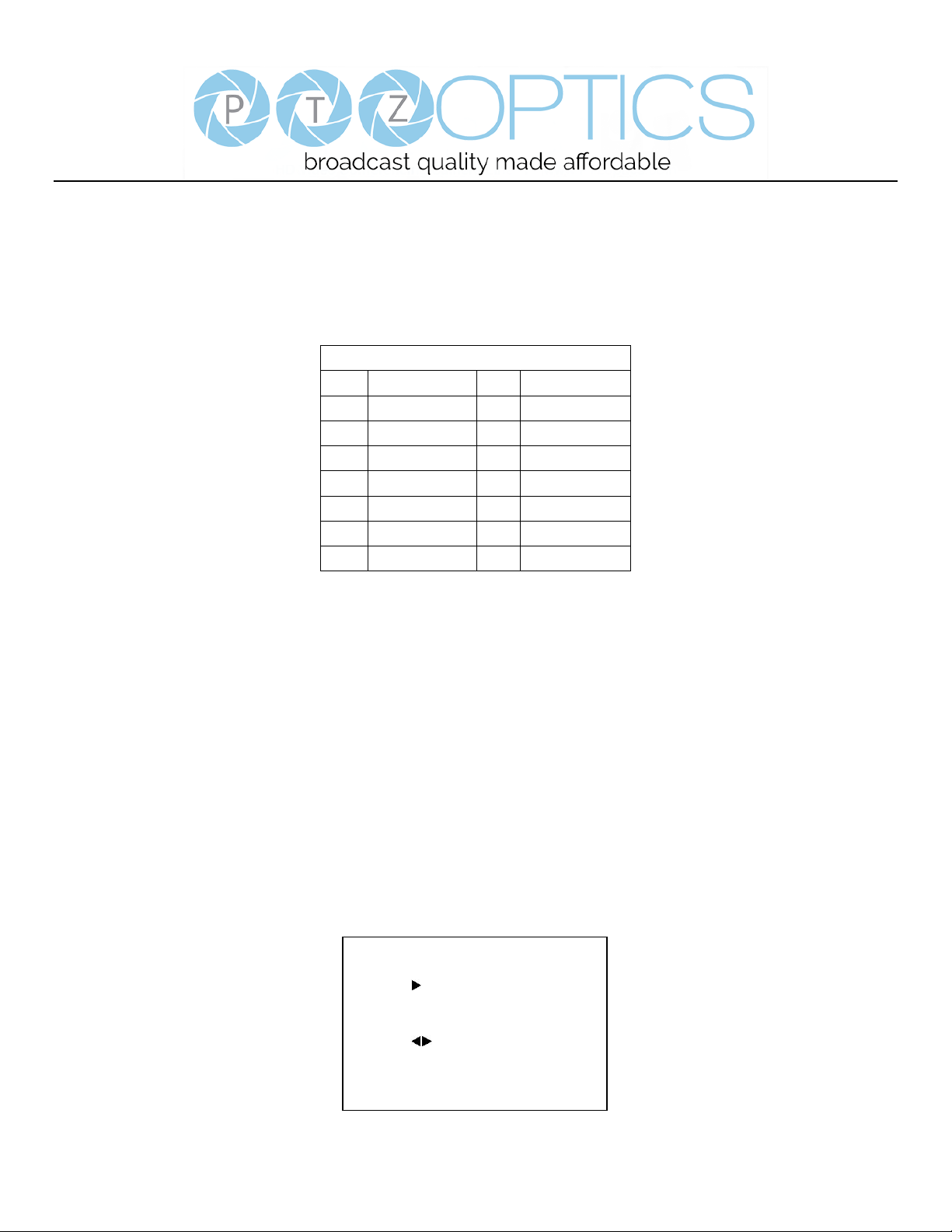
Step 5. (Optional) If you want to restore the factory default settings, press [MENU] button to display the OSD menu. Select
the item [MENU] -> [RESTORE DEFAULT] -> [Restore]. Set the value [Yes], press [HOME] button to restore the factory
default settings.
RESTORE DEFAULT
Restore Yes
Change Value
[Home] OK
[Menu] Back

Page 4 of 57
Rev 1.2 6/18
Features
1. Supports UVC compatible USB 3.0 transmission, the highest rate up to 5Gbps, ensuring real-time lossless HD data
transmission.
2. Supports simultaneous USB 3.0, HDMI and IP network streaming up to 1080p-60.
3. Supports non-simultaneous CVBS (composite video) output via RCA connector (480i or 576i).
4. Includes Panasonic's high quality, 1/2.7 inch, 2.07 million effective pixels, HD CMOS sensor, which can produce a
maximum 1920 x 1080 image with a high quality, maximum output frame rate of 60 fps (frames per second).
5. Ultra-high frame rate 60fps for HDMI and USB and up to 120fps for IP Streaming (120fps at 720p only).
6. Supports IP streaming via RTSP and RTMP and using H.264, H.265 and MJPEG.
7. Microphone & AAC Audio Stream Encoding for IP stream & USB 3.0 – Use a line-level microphone to embed audio.
Uses AAC audio encoding for better sound quality and smaller bandwidth usage.
8. Includes an Olympus, high-quality, telephoto lens, supporting 12x optical zoom and optional 16x digital zoom with wide
angle 60.7 degree horizontal field of view in widest zoom setting.
9. The high SNR (signal to noise ratio) of the CMOS sensor (≥55dB), combined with 2D and 3D noise reduction algorithms,
effectively reduces noise, even under low illumination conditions.
10. Includes DRC (dynamic range control), allowing for greater image quality and detail across images that are both well-lit
and shadowed in the same frame.
11. Includes RS232 and RS485 interfaces for wired remote control. All of the parameters of the camera can be remotely
controlled by high-speed communications for joystick and central control system applications.
12. Includes web-based IP remote control interface.
13. Freeze - Allows freezing of video image on all outputs to allow for calling next preset without showing camera motion.

Page 5 of 57
Rev 1.2 6/18
Product Specifications
Model
PT20X-USB-GY-G2 and PT20X-USB-WH-G2
Type
PTZ Optics USB 3.0 HD 1080p Color Video Camera (GEN 2)
Features
Video System
1080p/60, 1080p/50, 1080i/60,1080i/50, 1080p/30, 1080p/25, 720p/60, 720p/50, 720p/30, 720p/25
CVBS: 480i, 576i
Sensor
Panasonic 1/2.7", CMOS, Total Pixels: 2.12M, Effective Pixels: 2.07M
Scanning Mode
Progressive
Lens
20x; f4.42mm – 88.5mm; F1.8 – F2.8
Digital Zoom
16x
Minimal Illumination
0.5 Lux (@F1.8, AGC ON)
Shutter
1/30s - 1/10000s
White Balance
Auto, 3000K/Indoor, 4000K, 5000K/Outdoor, 6500K-1, 6500K-2, 6500K-3, One Push (ok), Manual
Backlight Compensation
Yes
Digital Noise Reduction
2D & 3D Digital Noise Reduction
Video S/N
≥55dB
Horizontal Angle of View
3.36° - 60.7°
Vertical Angle of View
1.89° - 34.1°
Horizontal Pan Range
±170°
Vertical Tilt Range
-30° to +90°
Pan Speed Range
1.7° - 100°/s
Tilt Speed Range
1.7° - 69.9°/s
Ceiling Installation
Yes
Image Mirroring
Yes
Number of Presets
255
Preset Accuracy
0.1°
Video coding standards
H.264, H.265, MJPEG
Video Freeze
Yes
Face Detection
Via Future Firmware Update
Local USB 2.0 Storage
Via Future Firmware Update
Input/Outp.ut
USB Ports
1x USB 2.0 Type A Female (for future local video file storage)
1x USB 3.0 Type B Female
HD Output
1x USB 3.0, B-type female
1x HDMI Ver. 1.3
Page 6 of 57
Rev 1.2 6/18
1x RJ45 IP 10/100/1000 Ethernet Port
SD Output
1x CVBS: 3.5mm jack, 1Vp-p, 75Ω (requires adapter cable to connect to standard RCA input)
Network Interface and Output
1x RJ45: 10M/100M/1000M Adaptive Ethernet port
Audio Input
1-ch 3.5mm audio interface, LINE IN (embedded on IP Stream & USB 3.0 only)
Control Input / Output
1x RS-232 In: 8pin Mini-DIN, Max Distance: 30m
Protocols: VISCA/Pelco-D/Pelco-P
1x RS-232 Out (pass-through): 8pin Mini-DIN, Max Distance: 30m
Protocols: VISCA/Pelco-D/Pelco-P
1x RS-485: 2pin phoenix port, Max Distance: 1500m
Protocols: VISCA/Pelco-D/Pelco-P
IP Video Features
Video Compression
H.265/H.264/M-JPEG
Video Stream
Main Stream, Sub Stream
Main Stream Resolution
1920x1080, 1280x720, 1024x576
Sub Stream Resolution
720x576, 720x480, 320x240
Video Bit Rate
128Kbps ~ 8192Kbps
Bit Rate Type
Variable Rate, Fixed Rate
Frame Rate
50Hz: 1fps ~ 50fps, 60Hz: 1fps ~ 60fps
Audio Compression
AAC
Audio Bit Rate
96Kbps, 128Kbps, 256Kbps
Support Protocols
TCP/IP, HTTP, RTSP, RTMP, DHCP, Multicast, etc.
USB Video Features
Operating System
Windows XP, Windows Vista, Windows 7, Windows 8.1, Windows 10, Mac OS X, Linux
Color System
YUV 4:2:2
Video Format
USB3.0 - 1080p/60, 1080p/50, 1080p/30, 1080p/25, 720p/60, 720p/50, 720p/30, 720p/25
USB2.0 (through USB3.0 port only) - 960x540p/30, 960x540p/25, 640x360p/60, 640x360p/50,
1280x720p/25
UVC PTZ Control
Yes (UVC 1.5)
General Specifications
Power Connector
JEITA type (DC IN 12V)
Input Voltage
12VDC (10.8 - 13.0V DC)
Current Consumption
1.0A (Max)
Operating Temperature
23°F - 104°F [-5°c - 40°c]
Storage Temperature
-4°F - 140°F [-20°c - 60°c]
Power Consumption
12W (Max)
Dimensions (w x h x d)
5.56” x 6.88” (8.0” full vertical tilt) x 5.88” [142mm x 175mm (204mm full vertical tilt) x 150mm
Weight
3.1 lbs. [1.38kg]
Page 7 of 57
Rev 1.2 6/18
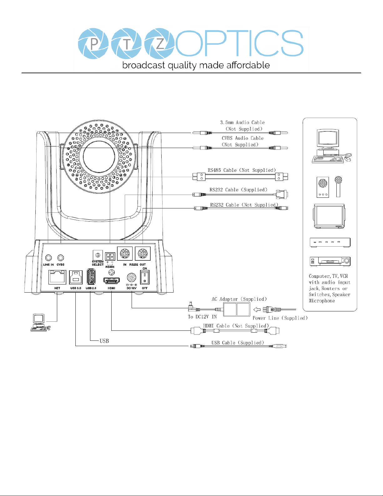
Main Unit
1. Audio LINE IN Interface (embeds in IP Stream & USB ) 7. Power switch
2. CVBS (composite video SD) Interface 8. DC 12V power jack
3. System select dial (resolution) 9. HDMI 1.3 (Digital Video Output)
4. RS485 jack 10. USB 2.0 (Future - USB Storage)
5. RS232 IN jack 11. USB 3.0 (USB Video Output)
6. RS232 OUT jack (pass through for daisy chain) 12. Network (IP streaming and control)
Page 8 of 57
Rev 1.2 6/18
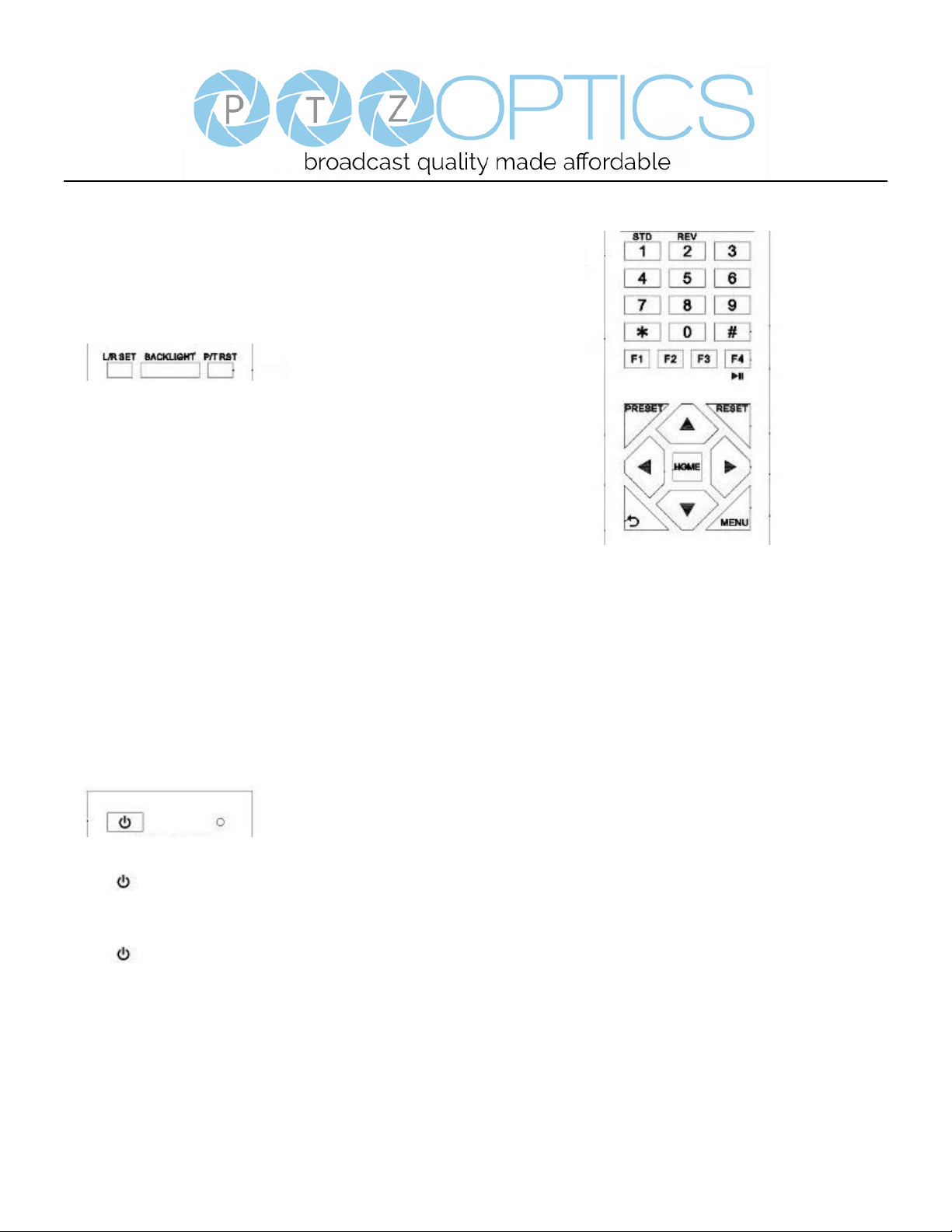
IR Remote Controller
1. Standby Button
Press this button to enter standby mode. Press it again to enter normal mode.
NOTE: Power consumption in standby mode is approximately half of the normal mode.
2. Position Buttons
To set preset or call preset.
3. * Button
For multiple function.
4&13. Set/Clear Preset Buttons
Set preset: Store a preset position
[PRESET] + Numeric button (0-9): Setting a corresponding numeric key preset
position
NOTE: Preset 0 - 9 via remote control and the rest from web, keyboard and the serial
port.
Clear preset: Erase a preset position [RESET] + Numeric button (0-9), or: [*] + [#] +
[RESET]: Erase all presets
5&14. Pan/Tilt Control Buttons
Press the arrow buttons to perform panning and tilting. Press the [HOME] button to
face the camera back to front.
6. Return Button
Press the button to back previous menu.
7. Zoom Buttons
Zoom+: Zoom In (Slow and fast speed)
Zoom-: Zoom Out (Slow and fast speed)
8. L/R Set Button
Set the left & right direction of the remote control.
[L/R Set] + [1]: Normal direction.
[L/R Set] + [2]: Left and right direction will be reversed.
9. Focus Buttons
Used for focus adjustment.
Press [AUTO] to adjust the focus on the center of the object automatically. To adjust
the focus manually, press the [MANUAL] button, and adjust it with [Far] (focus on far
object) and [Near] (focus on near object).

Page 9 of 57
Rev 1.2 6/18
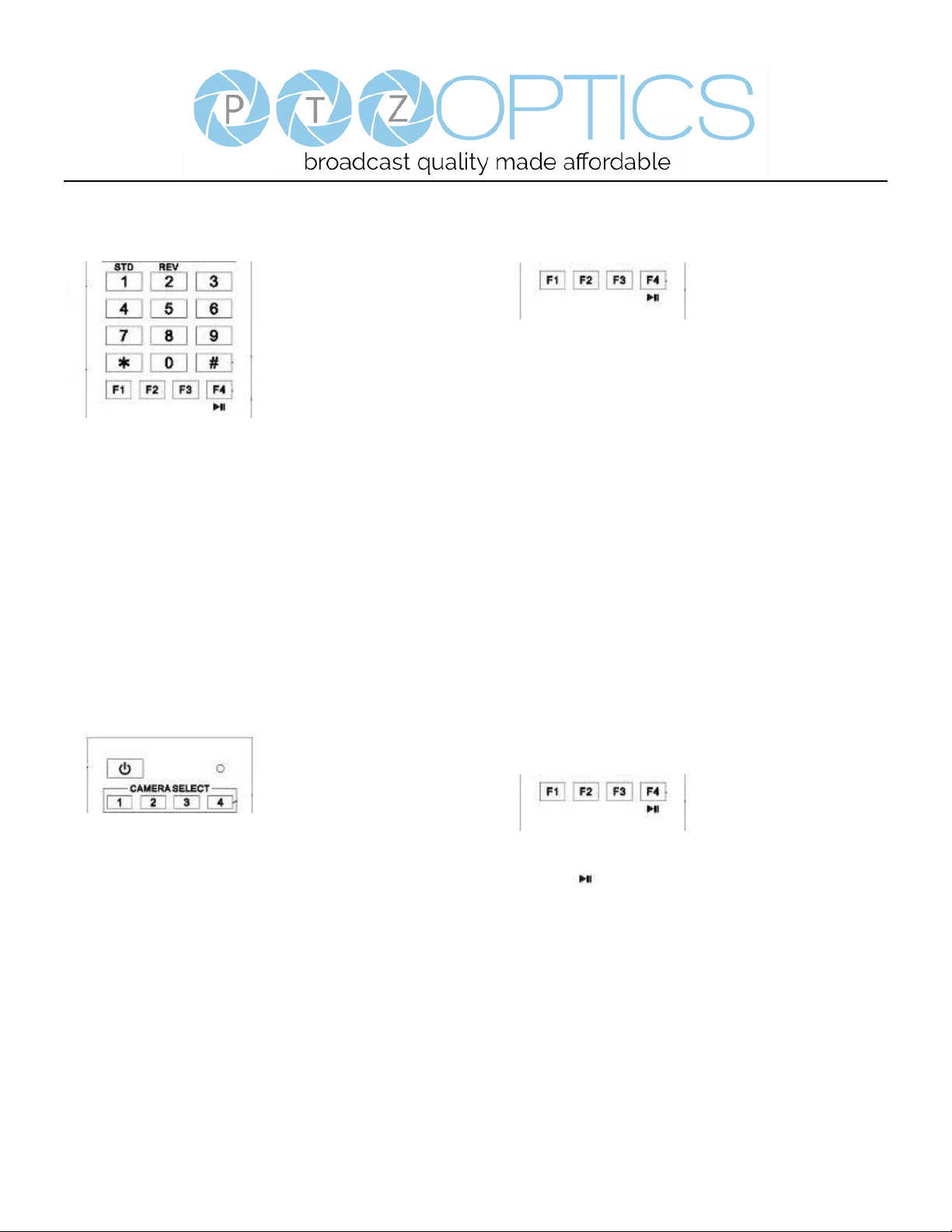
10. Camera Address Select Buttons
Press the button corresponding to the camera which you want to operate with the remote controller.
11. # Button
For multiple function.
12. Multiple Function Buttons
Function 1. Set camera IR address
Press 3 keys contiguously can set camera IR address as follow:
[*] + [#] + [F1]: Address 1
[*] + [#] + [F2]: Address 2
[*] + [#] + [F3]: Address 3
[*] + [#] + [F4]: Address 4
Function 2. Image freezing function
Press [F4] to start the freeze function. The word "Freeze" displays on the upper left corner. After five seconds, the display
disappears automatically (though the freeze feature continues). To cancel the freeze, press the [F4] key the word "Unfreeze"
displays on the upper left corner. After five seconds, the display disappears automatically.
15. Menu Setting
Menu button: Press this button to enter or exit the OSD menu.
16. Backlight Button
Backlight button: Press this button to enable the backlight compensation. Press it again to disable the backlight compensation.
NOTE: Effective only in auto exposure mode.
NOTE: If there is a light behind the subject, the subject will appear dark. In this case, press the backlight ON / OFF button. To
cancel this function, press the backlight ON / OFF button.
17. P/T RST Button
Press the button to self-calibrate pan and tilt once again.
Shortcuts for some ‘Set’ Functions
[*] + [#] + [1]: Display OSD menu in English
[*] + [#] + [3]: Display OSD menu in Chinese
[*] + [#] + [4]: Show IP address
[*] + [#] + [6]: Quickly restore the default settings
[*] + [#] + [8]: Show the camera version
[*] + [#] + [9]: Quickly set mount mode (flip / normal)1. Standby Button
Press this button to enter standby mode. Press it again to enter normal mode.
NOTE: Power consumption in standby mode is approximately half of the normal mode.
Page 10 of 57
Rev 1.2 6/18
Using the IR Remote Controller
When the camera is operational, you can use the remote
controller to perform panning, tilting, zooming and
focusing, as well as store and call back preset positions.
Button Instructions:
1. In these instructions, ‘press the button’ means to
press and release. A special note will be given if holding a
button down for more than one second is required.
2. When a button-combination is required, do it in
sequence (not simultaneously). For example, ‘[*] + [#] +
[F1]’means press [*] first and then press [#] and then
press [F1].
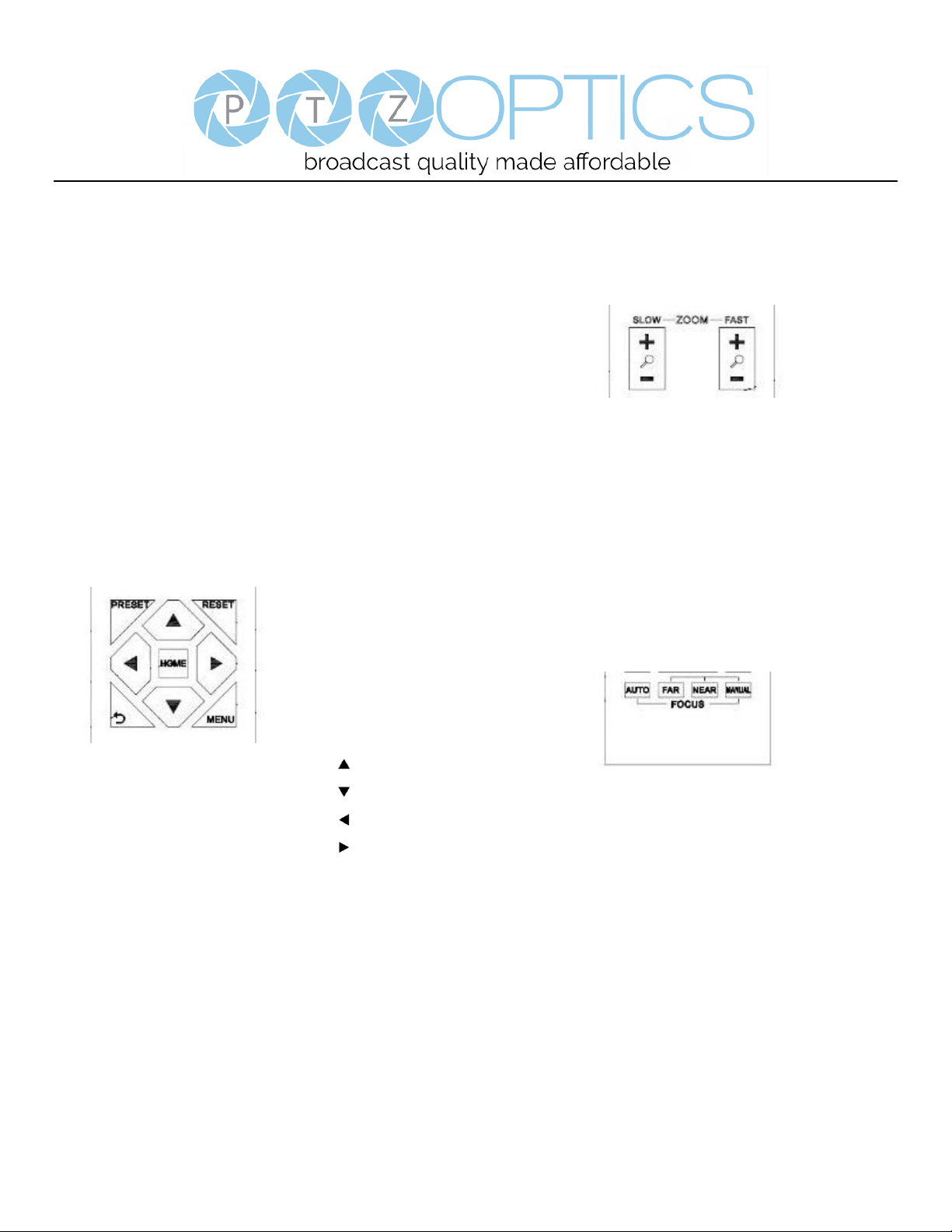
1. Pan/Tilt Control
Tilt up: Press [ ]
Tilt down: Press [ ]
Pan left: Press [ ]
Pan right: Press [ ]
Face the camera back to front: Press [HOME]
Press and hold the up/down/left/right buttons, to keep
panning or tilting from slow to fast, (until the camera
reaches the mechanical limit). The camera stops as soon
as the button is released.
2. Zoom Control
Zoom Out: press [+] button under FAST or SLOW
Zoom In: press [-] button under FAST or SLOW
Press and hold the button, to keep zooming in or out
(until the lens reaches the mechanical limit). The lens
stops as soon as the button is released.
3. Focus Control
AUTO: Change focus mode to AF, which allows the
camera to adjust the focus automatically on the center of
the image.
MANUAL: Change focus mode to MF, which allows the
user to adjust the focus manually (see FOCUS FAR &
FOCUS NEAR).
FOCUS FAR: Press [FAR] button (NOTE: Effective only
in MANUAL focus mode)
FOCUS NEAR: Press [NEAR] button (NOTE: Effective
only in MANUAL focus mode)
Page 11 of 57
Rev 1.2 6/18
Press and hold the FOCUS [FAR] or FOCUS [NEAR]
button, allows for continuous adjustment, stopping as
soon as the button is released.
4. BACKLIGHT. L/R SET and P/T RST Controls
Reverse Pan controls direction: Press and hold [L/R SET]
button while pressing [1] aka [STD] button for normal
pan controls. Press and hold [L/R SET] button while
pressing [2] aka [REV] button for reversed pan controls.
Backlight Compensation Control: Press [BACKLIGHT]
button to enable backlight compensation. Press it again to
disable backlight compensation. (Note: Backlight is only
effective in full auto exposure mode)
Pan Tilt Control Self Calibration: Press [P/T RST] button
to recalibrate the Pan and Tilt limits.
5. Standby Control
Press [ ] button to put camera in ‘standby’ mode. In
standby mode the camera will provide no image, respond
to no commands and use less than half its normal power.
Press [ ] button again to put camera in normal mode.
6. Presets - Setting and Clearing
1. To store a preset position: The user should manually
setup the desired shot using the Pan Tilt and Zoom
controls. Press the [PRESET] button first and then press
the numeric button [0-9] to which you want to assign the
shot. Ten total preset positions (0-9) are available from
the IR remote control (255 available via RS232/RS485/IP
Interfaces).
2. To erase the memory content of a preset position: The
user should press the [RESET] button first and then press
the numeric button 0-9 associated with that preset.
Note:
Pressing [*] + [#] + [RESET] in sequence will erase
all presets in the memory.
Page 12 of 57
Rev 1.2 6/18
7. Recalling Presets
Pressing any of the numeric buttons [0-9] directly will
recall a stored preset position and settings.
Note:
No action will be executed if a specific numeric preset
position has not yet been saved.
Note:
Presets assigned via the IP interface do not correlate to
presets set via the IR remote control.
8. Camera Selection
Press the [1-4] button corresponding to the camera with
the IR address that you want to operate. This allows for
up to 4 cameras to be operated via the same IR remote in
the same room.
9. Camera IR Address Set
Press 3 buttons in the sequence shown below to
set/change the camera’s IR address. This allows up to 4
cameras to be controlled from the same IR remote control.
Be sure that only one camera is picking up the IR signal
when you perform this function. If multiple cameras
receive the command, they will all change to the new
address.
Address 1: [*] + [#] + [F1]
Address 2: [*] + [#] + [F2]
Address 3: [*] + [#] + [F3]
Address 4: [*] + [#] + [F4]
10. Image Freeze
Press the [ ] button to freeze or unfreeze the video
image. This can be useful while recalling presets to hide
camera motion from your viewers.
Page 13 of 57
Rev 1.2 6/18
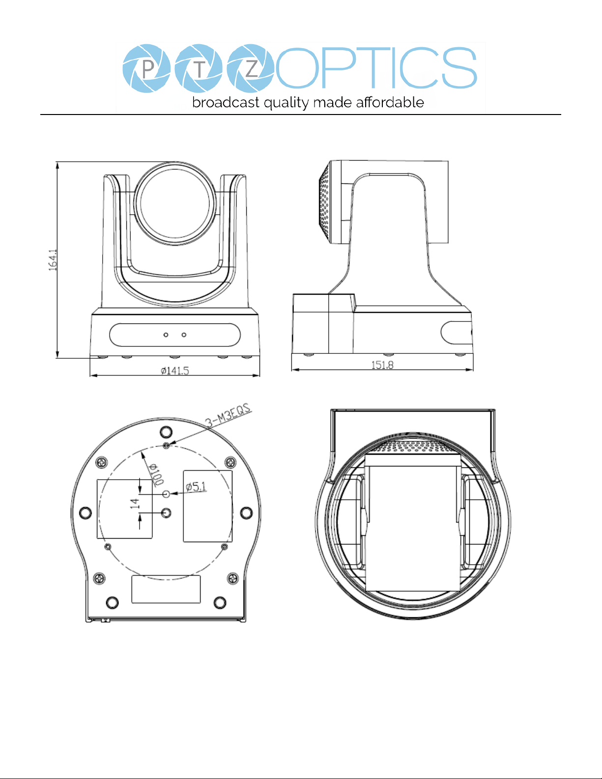
Dimensional Drawings (mm)
Page 14 of 57
Rev 1.2 6/18
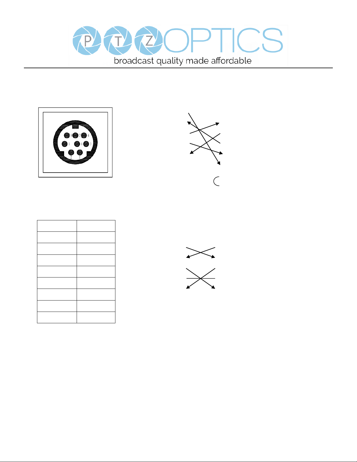
RS-232 Interface
Camera PC/Controller DB-9
1.DTR 1.CD
2.DSR 2.RXD
3.TXD 3.TXD
4.GND 4.DTR
5.RXD 5.GND
6.GND 6.DSR
7.IR OUT 7.RTS
8.NC 8.CTS
9.RI
For Control Daisy Chain
1st Camera 2nd Camera Mini DIN
1.DTR 1.DTR
2.DSR 2.DSR
3.TXD 3.TXD
4.GND 4.GND
5.RXD 5.RXD
6.GND 6.GND
7.IR OUT 7.NC
8.NC 8.NC
No.
Function
1
DTR
2
DSR
3
TXD
4
GND
5
RXD
6
GND
7
IR OUT
8
NC

Page 15 of 57
Rev 1.2 6/18
Serial Communication Control
In default working mode, the camera is able to connect to a VISCA controller with an RS232C serial interface.
➢ RS232 Communication Control
The camera can be controlled via RS232. The parameters of RS232C are as follows:
Baud rate: 2400, 4800 or 9600 bps.
Start bit: 1 bit.
Data bit: 8 bits.
Stop bit: 1 bit.
Parity bit: none.
➢ RS485 Communication Control
The camera can be controlled via RS485, Half-duplex mode, with support for VISCA, Pelco-D or Pelco-P protocol.
The parameters of RS485 are as follows:
Baud rate: 2400, 4800 or 9600 bps.
Start bit: 1 bit.
Data bit: 8 bits.
Stop bit: 1 bit.
Parity bit: none.
When powered on, Pan and Tilt will rotate to the maximum position of top right after the camera powered up. Then it will
return to the “center”. The process of initialization is now complete. (Note: If the position preset 0 has been stored, the
position preset 0 will be called up after initialization, in lieu of “center”). After initialization is complete, then the user can
control the camera with commands in the command list.
 Loading...