

Page 1
9800 Martel Road
Lenoir City, TN 37772
www.ps-engineering.com
PMA8000B
PMA8000B
Audio Selector Panel
Marker Beacon Receiver
High-fidelity Stereo Intercom System
Pilot’s Guide
Pilot’s Guide
and
and
Operation Manual
Operation Manual
202-890-0202 Revision 6 June 2008
Covered under one or more of the following Patent No.
4,941,187, 5,903,227, 6,160,496, 6,493,450
FAA-Approved: TSO C50c, C35d
June 2008 PMA8000B Pilot Guide
202-890-0202 Page 1
Page 2
This pilot guide provides detailed operating instructions for the PS
Engineering PMA8000B, Audio Selector Panel/Intercom Systems.
Please read it carefully before using the equipment so that you can
take full advantage of its capabilities.
This publication covers the basic operating areas of the PMA8000B
systems. They are Com Transceiver Selection, Audio Selector, Intercom, and Marker Beacon Receiver, utility jack and the configuration
buttons.
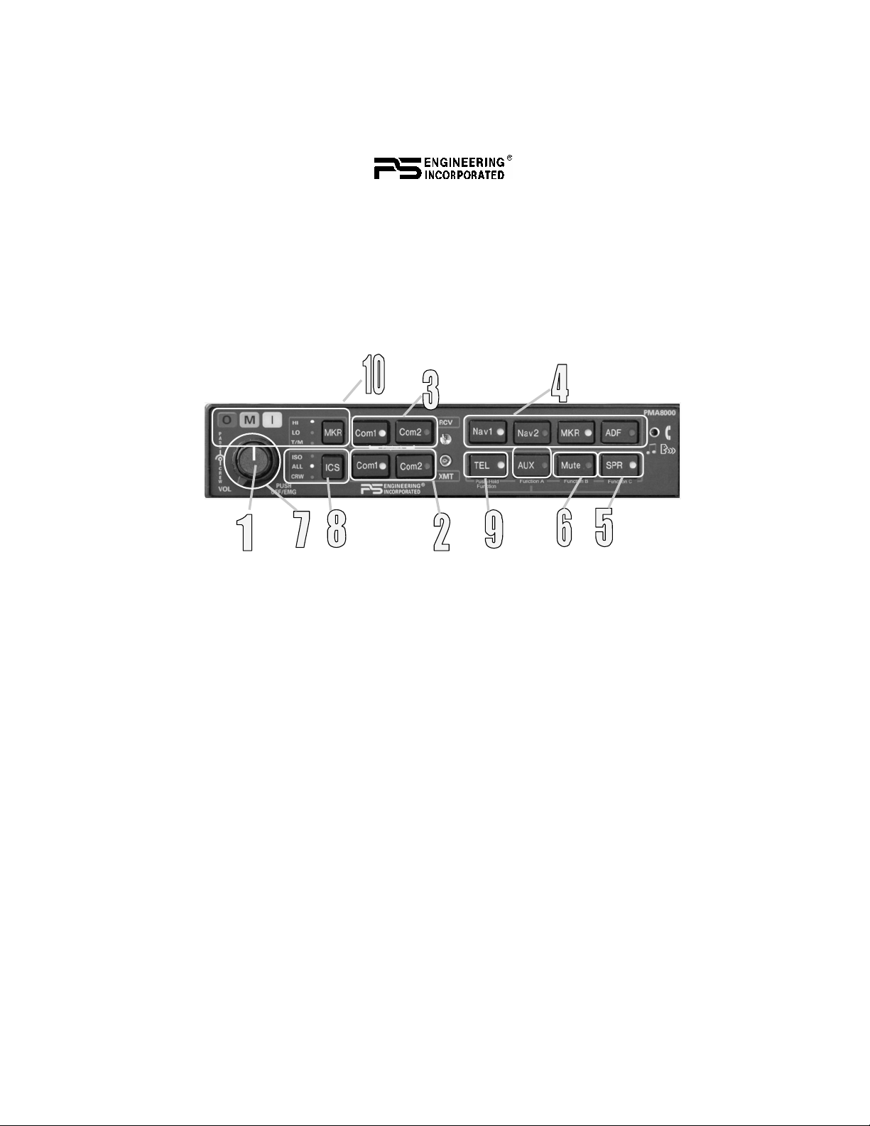
PMA8000B controls
Power Switch (1) (EMG-Fail Safe Operation)
Unit power is turned on and off by pushing the volume knob. In the
OFF or "EMG" position, the pilot headset is connected directly to
Com 1 as well as unswitched input #1. This allows communication
capability regardless of unit condition. Any time power is removed or
turned
OFF, the audio selector will revert to fail-safe mode.
The power switch controls all audio selector panel functions, intercom and marker beacon receiver. All pushbutton selections will be
remembered and return to the last state when turned on.
Communications Transmit (XMT) Selection (2)
There are two pushbuttons associated with the transmitter selection.
The two lower buttons (# 2) control which transceiver is selected for
transmit. The top row of pushbuttons (# 3) allows selection of the receiver audio. Push the lower button to select the desired COM transmitter.
Page 2 202-890-0202 PMA8000B Pilot Guide Rev. 6
Page 3
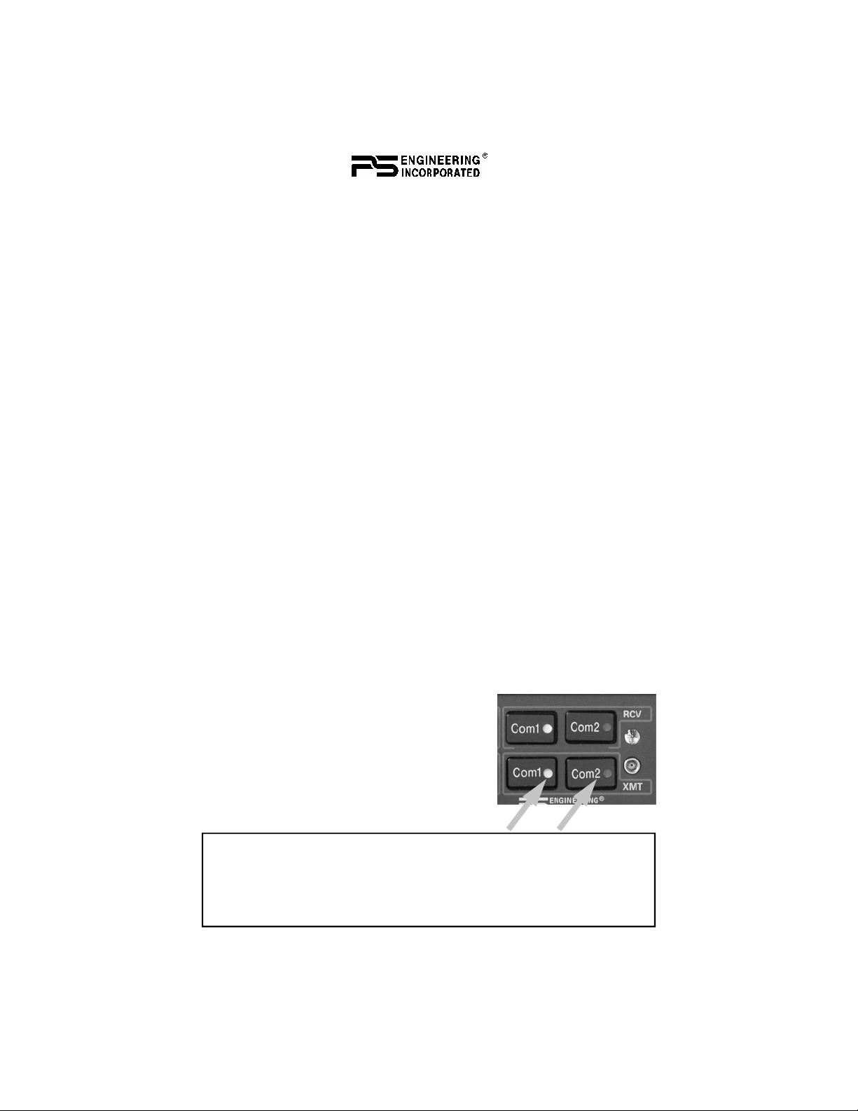
The PMA8000B-Series has an automatic selector system. Audio from
the selected transceiver is automatically heard in the headsets and
speaker (if selected). You can check this function by switching from
C
OM 1 transmitter to Com 2 transmitter by pressing the COM 2 trans-
mitter selector pushbutton. Note that the associated Com 2 receive
pushbutton indicator light that is located immediately above the Com
2 transmitter pushbutton turns green. This guarantees that the pilot
will always hear the audio from the transceiver selected for transmit.
The PMA8000B “remembers” the receiver selection, so that when
switching transmitters from C
previously selected, C
OM 1 audio will continue to be heard. This
OM 1 to COM 2, if COM 2 audio was
eliminates the pilot having to switch Com 1 audio back on, after
changing transmitters.
When switching from C
ously selected, C
OM 1 audio will be switched off. In essence, switch-
OM 1 to COM 2 while Com 2 was not previ-
ing the mic selector will not override prior selection of COM receiver
audio.
In normal (not split) modes, the PMA8000B gives priority to the pilot’s radio Push-To-Talk (PTT). If the copilot it transmitting, and the
pilot presses his PTT, the pilot’s microphone will be heard over the
selected com transmitter.
In TEL mode, the pilot microphone and headphones are connected to
the cell phone. The pilot PTT will switch the pilot mic to the selected
com transceiver, and allow continued aircraft communications to continue. (See Page 4—TEL—for more details)
The copilot will also be able to transmit on the other selected radio
with his PTT as well.
Split Mode
The split mode can be activated at any time
by pressing the C
buttons at the same time. This places the
pilot on C
Pilot on C
OM 1 and the copilot on COM 2.
OM 2 and Copilot on COM 1 is not
possible.
NOTE: Due to the nature of VHF communications signals, and
the size constraints in general aviation aircraft, it is probable
that there will be some bleed-over in the Split mode, particularly
on adjacent frequencies. PS Engineering makes no warranty
about the suitability of Split Mode in all aircraft conditions.
June 2008 PMA8000B Pilot Guide
OM 1 and COM 2 XMT
202-890-0202 Page 3
Page 4
Note: Split Mode does not turn off Nav, ADF, or Aux selected audio to
pilot. However, the copilot will only hear the selected com receiver and
unswitched inputs.
Swap Mode (Switch from Com 1 to Com 2 remotely)
With a yoke mounted, momentary switch, the pilot can change from
the current Com transceiver to the other by depressing this switch. To
cancel "Swap Mode," the pilot may either press the yoke mounted
switch again, or select a different Com with the XMT buttons.
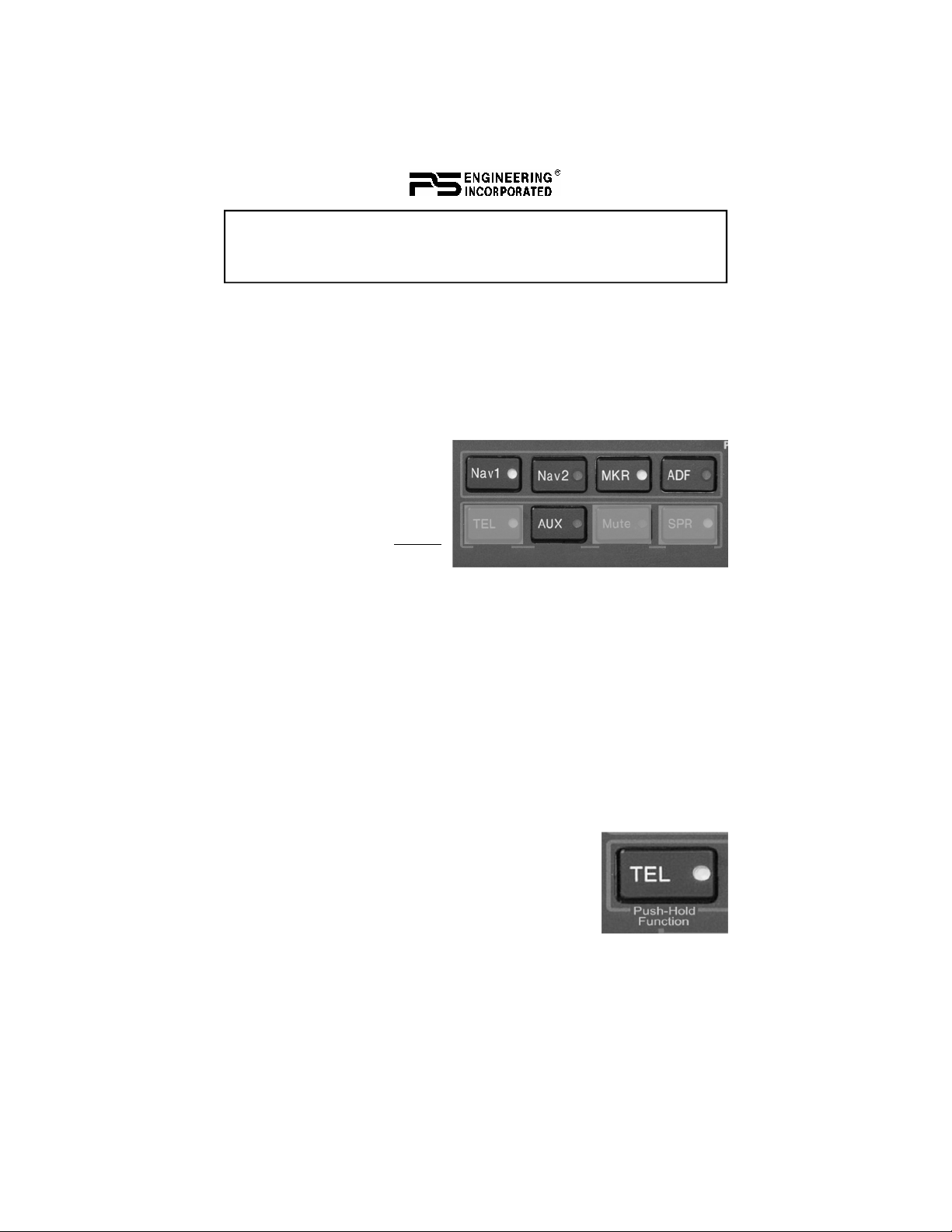
Audio Selector (4)
Navigation receiver audio is
selected through five momentary, push-button, backlit
switches. You will always
hear the audio from the selected transceiver.
The users can identify which receivers are selected by noting which
green switch LEDs are lit. Navigation aid audio push buttons are labeled Nav 1, Nav 2, MKR (Marker), ADF and AUX (auxiliary).
DME audio (if present) will come through when the AUX button is
selected. When one of these buttons is pressed, the mode is active,
and the LED will illuminate. Press the switch again and it will be
"off" and remove that receiver from the audio output.
In SPLIT mode, only the pilot will hear selected navigation audio.
Telephone (TEL) (9)
The TEL mode serves as a full duplex interface and
distribution for telephone systems such as AirCell
or portable cellular phones with earpiece jacks.
Pressing the TEL button activates the telephone
mode.
This connects the telephone to the users as follows:
In ALL intercom mode, all crew and passengers
will be heard on the phone when they speak. Com and other selected
radio audio is also heard in the headsets. If the pilot or copilot pushes
the radio PTT, their mic will be transferred to the selected Com radio.
Page 4 202-890-0202 PMA8000B Pilot Guide Rev. 6
Page 5
The telephone party will not hear ATC communications, and vice
versa.
In CREW mode, only the pilot and copilot are connected to the telephone. Passengers will not hear the telephone. The pilot and copilot
will also have transmit capability on the other selected transceiver.
In ISO intercom mode, when the PMA8000B is in the TEL mode,
the pilot position is in the "Phone Booth." Only the pilot will hear the
telephone, and only he will be heard. He will also have access to Com
1 or 2, and will transmit on that radio using the PTT. All selected audio is provided to the pilot.
Note: Because the cell-phone uses an intercom circuit, all stations on that circuit will lose intercom capability when the cell
phone is in use.
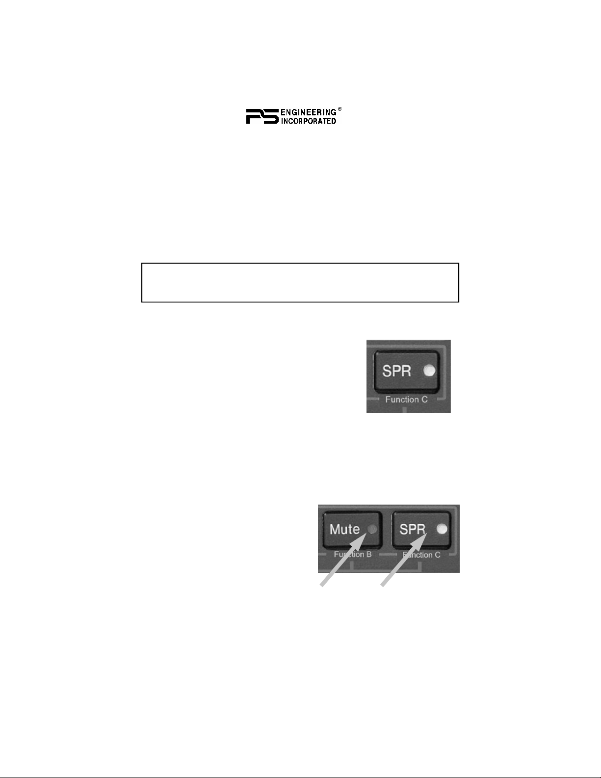
Speaker Amplifier (5)
The SPR in the lower right section stands for
speaker. This switch will place all selected audio
on the cockpit speaker when this switch is selected. Except for the unswitched audio, the
speaker amplifier is not active in the "Split
Mode”.
Unswitched audio 1, 3 and 4 (the inputs dedicated to autopilot disconnect, altimeter warning, etc.) may come
through the speaker regardless of the speaker button position.
Depending on installation, important audio annunciations such as radar altimeter or autopilot disconnect will come over the speaker even
if it is not selected, while other unswitched, but muted inputs, such as
GPS alerts, will only be present if the
SPR button is selected. Consult your
professional avionics installer for
these important configuration details.
Public Address Function
To access PA function, press the
Mute and SPR buttons simultaneously. The Mute and SPR LEDs
will blink to indicate the audio panel is in PA mode. The copilot can
continue to use the selected com radio while the pilot will now be
heard over the speaker. To exit PA mode, push Mute and SPR again.
June 2008 PMA8000B Pilot Guide
202-890-0202 Page 5
Page 6

Intercom Operation
IntelliVox® VOX-Squelch
No adjustment of the IntelliVox® squelch control is necessary. There
is no field adjustment. Through three individual signal processors, the
ambient noise appearing in all six microphones is constantly being
sampled. Non-voice signals are blocked. When someone speaks, only
their microphone circuit opens, placing their voice on the intercom.
The system is designed to block continuous tones, therefore people
humming or whistling in monotone may be blocked after a few moments.
For consistent performance, any headset microphone must be placed
within ¼-inch of your lips, preferably against them. (ref: RTCA/DO-
214, 1.3.1.1 (a)). It is important to have the microphone element parallel to your mouth, and not twisted inside the cover.
Note: For optimum microphone performance, we recommend
use of a Microphone Muff Kit from Oregon Aero (1-800-888-
6910). This will not only optimize VOX performance, but will
improve the overall clarity of all your communications.
Oregon Aero MicMuff Part Numbers
Headset
Manufacturer
Bose Dynamic
Electret
M87
Model Part Number
90010
90015
90020
David Clark H10-30
H10-20, H10-40
H10-13.4, 13X
H20-10X
Lightspeed All 90015
Peltor 7003
ANR Pro, 7000
Pilot 11-20, 11-90, 1776, DXL 90015
Sennheiser All 90015
Telex Airman 750, AIR4000
AIR3000, Echelon 100
Page 6 202-890-0202 PMA8000B Pilot Guide Rev. 6
90010
90015
90015
90015
90010
90015
90010
90015
Page 7

It is also a good idea to keep the microphone out of a direct wind
path. Moving your head through a vent air stream may cause the In-
telliVox® to open momentarily. This is normal.
The IntelliVox® is designed to work with normal aircraft cabin noise
levels (70 dB and above). Therefore, it may not always recognize
speech and clip syllables in a quiet cabin, such as in the hangar, or
without the engine running. This is also normal.
Intercom Volume Control (7)
The small volume control knob adjusts the
loudness of the intercom for the pilot and copilot. It has no effect on selected radio levels,
music input levels or passengers' volume level.
The larger, outer volume control knob controls
intercom volume or the passengers. It has no
effect on radio or music levels.
Adjust the radios and intercom volume for a
comfortable listening level. Most general aviation headsets today
have built-in volume controls; therefore, volume also can be further
adjusted at the individual headset.
Mono Headsets in Stereo Installation
The pilot and copilot positions work with stereo or mono headsets.
All passenger headsets are connected in parallel. Therefore, if a monaural headset is plugged in to a PMA8000B Stereo installation, one
channel will be shorted. Although no damage to the unit will occur,
all passengers will lose one channel, unless they switch to the
“MONO” mode on the headset. PS Engineering modifies headsets to
add stereo capability, using high-fidelity speakers. Contact factory
(865-988-9800) for details.
Intercom Modes (8)
The “ICS” pushbutton switch on
the left side of the panel provides
the selection of the three intercom
modes. The description of the
intercom mode function is valid
only when the unit is not in the
"Split" mode. Then, the pilot and
copilot intercom is controlled
with the Mute button.
June 2008 PMA8000B Pilot Guide
202-890-0202 Page 7
Page 8
This button cycles through the intercom modes, from top to bottom
and then back up, ISO, ALL, Crew, ALL, and ISO. An LED shows
the active mode .
I
SO: The pilot is isolated from the intercom and is connected only to
the aircraft radio system. He will hear the aircraft radio reception (and
sidetone during radio transmissions). The copilot and passengers will
hear the music sources as configured by the audio panel configuration
Function keys. See page 11—Smart Function Keys for more details.
LL: All parties will hear the aircraft radio and intercom. Crew will
A
hear Entertainment 1, passengers can hear Entertainment 1 or 2. During any radio or intercom communications, the music volume automatically decreases. The music volume increases gradually back to
the original level after communications have been completed.
REW: Pilot and copilot are connected on one intercom channel and
C
have exclusive access to the aircraft radios. Again, the music that the
crew and passengers will hear is determined by the Smart Function
Keys.
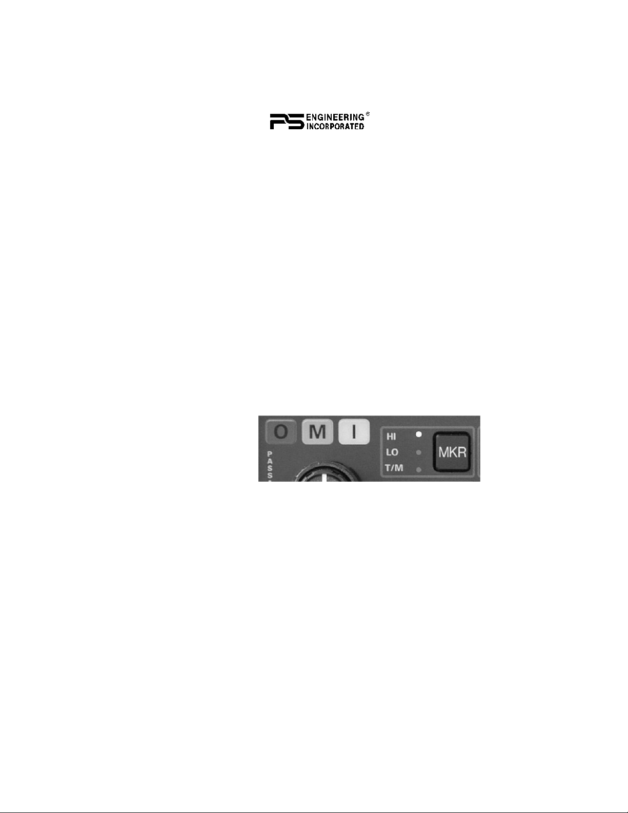
Marker Beacon Operation (10)
The Marker Beacon
Receiver uses visual
and audio indicators
to alert you when the
aircraft passes over a
75 MHz transmitter.
The Blue lamp, labeled “O”, is the Outer Marker lamp and has an associated 400-Hertz
'dash' tone. The lamp and tone will be keyed at a rate of two tones/
flashes per second when the aircraft is in the range of the Outer
Marker Beacon.
The Amber lamp, labeled “M”, is the Middle Marker lamp and is coupled with a 1300 Hertz tone. It is keyed alternately with short 'dot' and
long 'dash' bursts at 95 combinations per minute.
The White lamp, labeled “I”, is the Inner marker and has a 3000 Hertz
'dot' tone. The lamp and tone will be keyed at a rate of six times per
second.
The audio from the Marker Beacon Receiver can be heard by selecting the "MKR" push-button switch. To adjust the volume level, there
is a service adjustment located on the top of the unit.
Page 8 202-890-0202 PMA8000B Pilot Guide Rev. 6
Page 9

A pushbutton is used to set the receiver sensitivity and to test the indicator lamps mute the marker audio.
Use "HI" sensitivity initially. This allows you to hear the outer
marker beacon about a mile out. Then touch the smaller MKR button
to switch into Low Sensitivity mode. “LO” sensitivity gives you a
more accurate location of the Outer Marker. Holding the MKR button
for one second activates marker test lamp, labeled "T/M" and illuminates all three lamps simultaneously to assure the lamps (internal and
external) are in working order. TST does not activate MM autopilot
sense output. Releasing the button returns to the last sensitivity.
Pressing the marker mode select (“T/M”) for one second will also
cause the marker audio to mute for that beacon. The next beacon received will re-activate the audio.
Internal Recorder System
The Intercom Recording System is a digital recording system allowing automatic storage and playback of aircraft radio traffic.
Operating as a continuous loop recorder, (first message received will
be the last heard), the recorder has 30 seconds of recording time, or
up to 16 messages. With its own built in VOX circuit, there are no
buttons to press to start recording. The system automatically begins to
record the instant the radio becomes active. Only the com radio selected for transmit is recorded, and only the pilot and copilot will hear
the playback audio.
Operation
Recording is automatic. To play
back the last recorded message,
press and hold the COM Receive
pushbutton associated with the
selected radio transmitter for
about one (1) second. You must
wait for the message to finish
playing before accessing the
prior message. To cancel the
playback, press and hold the playback button for two seconds (2). The
next time the button is pressed for one (1) second, the next earlier
message will be heard.
The playback will stop whenever there is more incoming selected
com audio, and the message can be replayed from the beginning.
June 2008 PMA8000B Pilot Guide
202-890-0202 Page 9
Page 10
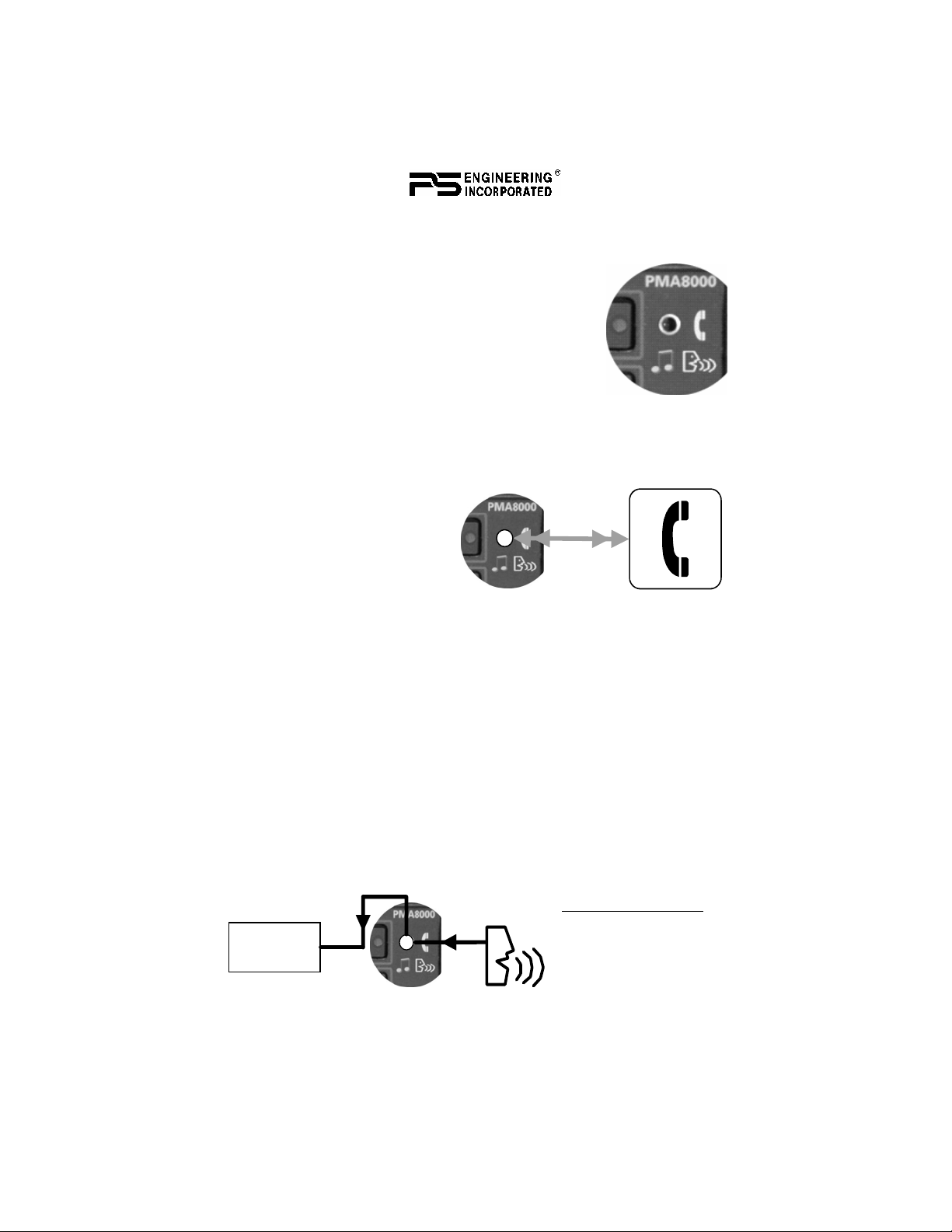
Utility Jack
The 2.5 millimeter (3/32”) jack on the front of the PMA8000B has
three distinct functions:
• Cell phone input
• Advisory audio input
• Music input
The use of this jack is controlled by three Smart
Function Keys (SFK) controlled from the front
panel. See Page 11—Smart Function Keys.
Cellular phone
When a cellular telephone is connected to this jack using a 2.5 mm to
2.5 mm adapter cord (PS Part
Number 425-006-7026), the
PMA8000B audio panel will
connect the intercom to the
cell phone when the “TEL”
button is pressed (9). When
the TEL mode is off, the telephone ringer audio will be
heard if it is present on the telephone’s output (ringer may be muted
by radio and intercom).
Audio Advisory Input
The front jack can be used as a priority advisory input for auxiliary
systems such as a GPS terrain advisory or portable traffic watch system. To prevent radio or intercom from muting this input, press the
“Mute” button.
NOTE
The front jack is no substitute for the certified installation of alerts
such as the GPS waypoint or autopilot tones. These still must be hard
wired into the back by your installer.
We’ve built some intelligence into the PMA8000B, too.
Smart Jack Function
When the PMA8000B
Crew
Page 10 202-890-0202 PMA8000B Pilot Guide Rev. 6
has a signal on music
#1 input coming in
from the rear connector, the front panel
Page 11
jack automatically becomes a Priority Advisory input, and is heard in
the crew headphones.
This input will NOT be muted by radio or intercom.
Music Input
When used as a music input, the front panel jack is treated as Music
#1. However, thanks to the function controls, it can be distributed to
all users, regardless of the intercom mode.
Smart Function Keys (SFK)
With Virtual Tech Support, the configuration process is self-directed.
Once you’ve set up your system, you don’t need to change it again,
unless you want to. The unit will always remember your settings.
Note: VTS annunciations will be stopped by any audio received on
the com radio selected for transmit.
These functions are non-essential and non-required and as such are
only an accessory capability. They don’t affect the audio panel’s primary function as a selector panel, aircraft intercom, or marker beacon
receiver. You can’t do anything with these buttons to prevent the
PMA8000B from doing its main job.
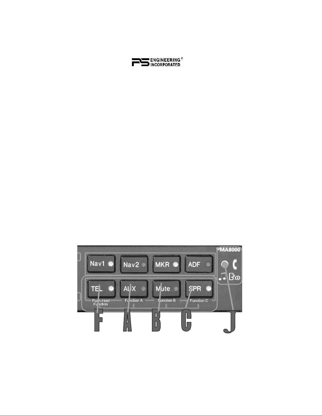
Looking at the front panel you’ll notice that the TEL, Aux, Mute and
SPR buttons have “Function” assignments.
To use these function keys A, B, C – press and hold “F” and then
press the desired key, “A” “B” or “C”.
June 2008 PMA8000B Pilot Guide
202-890-0202 Page 11
Page 12

There are three special functions. Function Button “A” is related to
the intercom function, and allows the crew to mute passengers’ intercom feed when radios are active.
Function Buttons “B” and “C” control how music is distributed in
your airplane.
Function A
AUX
Intercom Mode Music 1
State 1 State 2 State 1 State 2 State 1 State 2
Function B
MUTE
Propagation
Function C
SPR
Music Distribution
“Alternate
intercom
”
function
“Standard
Intercom
Function”
“Music #1
all headsets”
“Music
#1 distribution
crew.”
“Standard
Music
Distribution
“Alternate
music
distribution ”
Button Function Table
There are two music sources available to the PMA8000B. Music 1
input can be either on the front jack, OR the Music 1 input at the rear
connector (Pins 23 and 24, J2). Music 2 is wired into the rear connector, only (Pins 26 and 27, J2)
The volume of the audio annunciations and recorder playback can be
adjusted through a hole on the top of the unit marked “ANN VOL.”
Function “A”
Function “A” controls the distribution of aircraft radio within the intercom, as well as passenger intercom muting. In the “standard intercom function” mode, aircraft radios are distributed to all, when the
intercom is in the ALL mode. In CREW mode, only the pilot and copilot positions will hear aircraft radios.
When Function A is toggled into “Alternate Intercom Function,” the
passengers will NOT hear aircraft radios, even in the All mode. In
addition, when in the ALL mode, passengers will be able to converse
with the crew. However, when the aircraft radio becomes active, the
intercom audio from the passengers is muted, allowing the crew to
focus on the radio. Passengers will be able to talk to each other,
unless the radios are active AND the crew speaking on the intercom,
in this case the passengers will only hear the crew intercom, and their
microphone will be muted.
Page 12 202-890-0202 PMA8000B Pilot Guide Rev. 6
Page 13
Function “B”
Function Button “B” allows you to either send the music 1 input to all
intercom stations, all of the time, or have the normal rules apply to
our music inputs.
When “Music number one distribution, all headsets” is selected, music 1 (or the front panel utility jack) will be distributed to all headsets
and is independent of the intercom mode switch. Therefore, even in
the CREW mode, the passengers will hear Music 1, even though they
will not hear the intercom or radios.
This mode allows you to use a single in-flight entertainment source
aboard, and to send it everywhere, even in crew mode. The music
muting will be normal, and follow the selected mode of the crew or
passengers.
When you select Function “B,” for the alternate function, you hear
“Music number one distribution, Crew.” Now, music input 2 will follow the modes in Function “C.”
Passengers
Music 1
Pilot & Copilot
Music Distribution ICS Dependent
ALL M o de
ICS
Mus ic 1
Passengers
ICS
Copilot
Pilot
Music Distribution Dependent
ISO Mode
Music 2
Music 1
Music Distribution Dependent
Passengers
Pilo t & C opilot
CREW Mode
Music Distribution Depends on Intercom Mode
Function “C”
Function “C” allows you to configure your music to be either independent of the intercom mode, or to make Music 2 dependent on the
intercom mode.
When you press Function “C,” you’ll hear, “Alternate Music distribu-
tion.” In this case, Music 2 will be active only when the intercom is in
the CREW mode, and only the passengers will hear it. This distribution is similar to other brands of audio panels. It allows the passengers
June 2008 PMA8000B Pilot Guide
202-890-0202 Page 13
Page 14

to have their music source come on only when they are not hearing
the crew.
Mus ic 2
Mus ic 1
Music Distribution Independent
All Mo d e
Passengers
Pilot & Cop ilot
Mus ic 2
ICS
Mus ic 1
Music Distribution Independent
ISO Mode
Passengers
Copilot
Pilot
ICS
Mus ic 2
Mus ic 1
Music Distribution Independent
Crew Mode
Passengers
Pilo t & Co pilot
Music Distribution Independent of Intercom Mode
Press again, and you will hear “Standard Music Distribution.” In this
mode, the music inputs are independent. Music 2 becomes active, and
will always be presented only to the passengers on the intercom. Music 1 is only available to the pilot and copilot. The intercom mode
switch doesn’t have any affect on the music distribution.
When the music is independent, Music 1 will always go to the pilot
and copilot positions, and is never heard by the passengers. Music 2 is
always heard by the passengers, and never by the pilot and copilot.
This mode is useful if your passengers have a different interest in entertainment or are watching a DVD, but do not want to be excluded
from the intercom conversations.
Music Muting
There are two SoftMute™ muting circuits.
The front panel "Mute" button will always
control the Mute function for music 1. It will
also control the muting of the front panel utility jack, when Music 1 is NOT active.
The SoftMute™ circuit will cut the music almost completely out
whenever there is conversation on the radio or intercom. When that
conversation stops, the music returns to the previous level comfortably, over a second or so.
The pilot and copilot have one muting circuit, which is controlled by
the front panel button labeled “Mute.” When this button is pressed,
the PMA8000B goes into the Karaoke Mode, and the music will not
Page 14 202-890-0202 PMA8000B Pilot Guide Rev. 6
Page 15

mute for incoming radio or intercom conversation.
The passenger’s intercom also has a SoftMute™ circuit. It behaves
the same way as the crew; if the passengers will hear the radio, or talk
on the intercom, the music will mute. If the audio panel is in CREW
mode, then the radio reception will not affect the passenger music.
Passengers also have a Karaoke Mode. If the passengers are listening
to the music 1 input or front panel input, their Karaoke Mode is controlled by the front panel button labeled "Mute". If the passengers are
listening to the music 2 input, their Karaoke Mode is activated by an
external switch installed either in the panel, or connected to the AUX
button logic output pin on the PMA8000B.
Music 1 Volume
In general, we recommend adjusting the entertainment volume at the
sources, and only using this as a master gain control. However, the
Music 1 PMA8000B input can be adjusted from the front panel, if
desired, by pressing the combinations of keys listed.
Hold the AUX button, and repeatedly push the Mute (volume up) or
SPR (volume down) to step the volume level. There are 32 steps.
• AUX + Mute, increase volume
• AUX + SPR, decrease volume
Warranty & Service
In order for the factory warranty to be valid, the installations in a certified
aircraft must be accomplished by an FAA-(or other ICAO agency) certified
avionics shop and authorized PS Engineering dealer. If the unit is being installed by a non-certified individual in an experimental aircraft, a factorymade intercom harness must be used for the warranty to be valid.
PS Engineering, Inc. warrants this product to be free from defect in material
and workmanship for a period of three (3) years from the date of retail sale
by authorized PS Engineering dealer. During the first twelve (12) months of
the three-year warranty period, PS Engineering, Inc., at its option, will send
a replacement unit at our expense if the unit should be determined to be defective after consultation with a factory technician. For the remaining
twenty-four (24) months of the three-year warranty period, PS Engineering
will send a no-cost replacement unit at customer shipping expense.
All transportation charges for returning the defective units are the respon sibility of the purchaser. All domestic transportation charges for returning the
exchange or repaired unit to the purchaser will be borne by PS Engineering,
Inc. The risk of loss or damage to the product is borne by the party making
the shipment, unless the purchaser requests a specific method of shipment. In
June 2008 PMA8000B Pilot Guide
202-890-0202 Page 15
Page 16

this case, the purchaser assumes the risk of loss.
This warranty is not transferable. Any implied warranties expire at the expi-
ration date of this warranty. PS Engineering SHALL NOT BE LIABLE FOR
INCIDENTAL OR CONSEQUENTIAL DAMAGES. This warranty does
not cover a defect that has resulted from improper handling, storage or preservation, or unreasonable use or maintenance as determined by us. This warranty is void if there is any attempt to dissemble this product without factor y
authorization. This warranty gives you specific legal rights, and you may
also have other rights, which may vary from state to state. Some states do not
allow the exclusion of limitation of incidental or conseq uential damages, so
the above limitation or exclusions may not apply to you.
All items repaired or replaced under this warranty are warranted for the remainder of the original warranty period. PS Engineering, Inc. reserves the
rights to make modifications or improvements to the product without obligation to perform like modifications or improvements to previously manufactured products.
Factory Service
The units are covered by a three-year limited warranty. See warranty information. Call PS Engineering, Inc. at (865) 988-9800 before you return any
unit. This will allow the service technician to provide any other suggestions
for identifying the problem and recommend possible solutions.
After discussing the problem with the technician and you obtain a Return
Authorization Number, ship product to:
PS Engineering, Inc.
Attn: Service Department
9800 Martel Rd.
Lenoir City, TN 37772
(865) 988-9800 FAX (865) 988-6619
Email: contact@ps-engineering.com
Units that arrive without an RMA number, or telephone number for a
responsible contact, will be returned un-repaired. PS Engineering is not
responsible for items sent via US Mail.
PS Engineering, Inc. 2005 ©
Copyrighted information in this manual is subject to change without notice. PS Engineering reserves the right to improve or change the products or
contents of this manual, without notification of any person or agency. The contents of this pilot’s guide may be downloaded, stored and reprinted
for personal use provided that this copyright information is included. Commercial use is strictly prohibited. For further information contact the
Publications Manager at PS Engineering, Inc., 9800 Martel Road, Lenoir City, TN 37772. Phone (865) 988-9800
Page 16 202-890-0202 PMA8000B Pilot Guide Rev. 6
Copyright Notice
 Loading...