


9800 Martel Road
Lenoir City, TN 37772 www.ps-engineering.com
PMA6000 |
PMA6000M |
PMA6000C |
PMA6000M-C |
Audio Selector Panel with Intercom System and
Marker Beacon Receiver
Installation and Operation Manual
Flying never sounded so good™
FAA-Approved TSO C35d
TSO C50c
Document P/N 200-066-0100
Revision 1, March 2005
PS Engineering, Inc. 2005 ©
Copyright Notice
Any reproduction or retransmittal of this publication, or any portion thereof, without the expressed written permission of PS Engineering, Inc. is strictly prohibited. For further information contact the Publications Manager at PS Engineering, Inc., 9800 Martel Road, Lenoir City, TN 37772. Phone (865) 988-9800

PS Engineering
PMA6000 Series Audio Selector Panel and Intercom System
Installation Manual
|
|
Table of Contents |
|
Section I |
GENERAL INFORMATION................................................................................................ |
1-1 |
|
1.1 |
INTRODUCTION.................................................................................................................... |
1-1 |
|
1.2 |
SCOPE ..................................................................................................................................... |
1-1 |
|
1.3 |
EQUIPMENT DESCRIPTION................................................................................................ |
1-1 |
|
1.4 |
APPROVAL BASIS - FAA ..................................................................................................... |
1-2 |
|
1.5 |
SPECIFICATIONS .................................................................................................................. |
1-2 |
|
1.6 |
EQUIPMENT SUPPLIED ....................................................................................................... |
1-3 |
|
1.7 |
EQUIPMENT REQUIRED BUT NOT SUPPLIED................................................................ |
1-4 |
|
1.8 |
LICENSE REQUIREMENTS.................................................................................................. |
1-4 |
|
Section II -Installation.......................................................................................................................... |
2-1 |
||
2.1 |
GENERAL INFORMATION .................................................................................................. |
2-1 |
|
2.1.1 |
|
SCOPE................................................................................................................................. |
2-1 |
2.2 |
Unpacking and Preliminary Inspection .................................................................................... |
2-1 |
|
2.3 |
Equipment Installation Procedures........................................................................................... |
2-1 |
|
2.3.1 |
|
Cooling Requirements ......................................................................................................... |
2-1 |
2.3.2 |
|
Mounting Requirements ...................................................................................................... |
2-2 |
2.3.3 |
|
Mounting Rack Installation ................................................................................................. |
2-2 |
2.3.4 |
|
Connector Assembly............................................................................................................ |
2-2 |
2.4 |
Cable Harness Wiring .............................................................................................................. |
2-2 |
|
2.4.1 |
|
Noise.................................................................................................................................... |
2-2 |
2.4.2 |
|
Entertainment Input ............................................................................................................. |
2-3 |
2.4.3 |
|
External Push-to-Talk.......................................................................................................... |
2-3 |
2.4.4 |
|
Transmit Interlock ............................................................................................................... |
2-4 |
2.4.5 |
|
Power................................................................................................................................... |
2-4 |
2.4.6 |
|
Existing KMA-24 Installation ............................................................................................. |
2-4 |
2.4.7 |
|
"Swap" Mode....................................................................................................................... |
2-4 |
2.4.8 |
|
Backlighting ........................................................................................................................ |
2-4 |
2.4.9 |
|
Speaker Loads ..................................................................................................................... |
2-5 |
2.4.10 |
PA Mute.......................................................................................................................... |
2-5 |
|
2.4.11 |
Middle Marker Sense...................................................................................................... |
2-5 |
|
2.4.12 |
Unswitched Inputs .......................................................................................................... |
2-5 |
|
2.4.13 |
Intercom.......................................................................................................................... |
2-5 |
|
2.4.14 |
Digital recorder (-IRS units only)................................................................................... |
2-5 |
|
2.5 |
Adjustments.............................................................................................................................. |
2-6 |
|
2.6 |
Marker Antenna Installation..................................................................................................... |
2-6 |
|
2.7 |
Communications Antenna Installation Notes ........................................................................... |
2-6 |
|
2.8 |
Unit Installation........................................................................................................................ |
2-6 |
|
2.9 |
Post Installation Checkout........................................................................................................ |
2-7 |
|
2.9.1 |
|
Required Test Equipment .................................................................................................... |
2-7 |
2.9.2 |
|
Power Test........................................................................................................................... |
2-7 |
2.9.3 Operational Checkout, 6000, 6000C, 6000M...................................................................... |
2-7 |
||
2.10 |
Marker Checkout, 6000M, 6000M-C Only.............................................................................. |
2-8 |
|
2.10.1 |
Operational Checkout, 3rd com version (6000C and 6000M-C)..................................... |
2-8 |
|
2.11 |
Final Inspection........................................................................................................................ |
2-8 |
|
Section III OPERATION.................................................................................................................... |
3-1 |
||
3.1 |
SCOPE ..................................................................................................................................... |
3-1 |
|
3.2 |
Audio Selector (All models)..................................................................................................... |
3-1 |
|
3.2.1 |
|
Speaker Amplifier................................................................................................................ |
3-1 |
3.3 |
Mic Selector Switch (Fail Safe Operation) .............................................................................. |
3-1 |
|
3.3.1 |
|
MicSelectorSwitch,Com3(6000C,6000MC) .................................................................................. |
3-2 |
3.3.2 Swap Mode (Switch from Com 1 to Com 2 remotely)........................................................ |
3-2 |
||
3.4 |
Split Mode (6000, 6000M)....................................................................................................... |
3-2 |
|
200-066-0100 |
Page ii |
Rev. 1, March 2005 |

PS Engineering
PMA6000 Series Audio Selector Panel and Intercom System
Installation Manual
3.5 |
Split Mode (6000C, 6000MC) ................................................................................................. |
3-2 |
3.6 |
Intercom ................................................................................................................................... |
3-3 |
3.6.1 Volume Control, Monaural (6000, 6000M, 6000C, 6000MC)............................................ |
3-3 |
|
3.6.2 Adjusting the VOX-Squelch control, (6000, 6000M, 6000MC)......................................... |
3-3 |
|
3.6.3 |
Intercom Modes................................................................................................................... |
3-3 |
3.6.4 Push to talk intercom mode ................................................................................................. |
3-4 |
|
3.6.5 Internal Recorder System (Option IRS, only) ..................................................................... |
3-4 |
|
3.7 |
Marker Beacon (PMA6000M, PMA6000M-C) ....................................................................... |
3-5 |
3.7.1 |
Middle Marker Sense........................................................................................................... |
3-5 |
3.7.2 External Marker Lights (6000M, 6000MC) ........................................................................ |
3-5 |
|
3.7.3 External Marker Audio Input (6000, 6000C) ...................................................................... |
3-5 |
|
3.7.4 |
Receiver Sensitivity............................................................................................................. |
3-5 |
Section IVWarranty and Service...................................................................................................... |
4-1 |
|
4.1 |
Warranty................................................................................................................................... |
4-1 |
4.2 |
Factory Service......................................................................................................................... |
4-1 |
Appendix A External PTT Hook Up..................................................................................................... |
A |
|
Appendix B- Installation Drawing ......................................................................................................... |
B |
|
Appendix D Top Connector wiring (Mono), PMA6000, PMA6000C, PMA6000M, PMA6000M-C D
Appendix F -Instructions for Continuing Airworthiness and FAA Form 337 .................................. |
E |
||||
Appendix G RTCA DO160B Environmental Qualification Form..................................................... |
F |
||||
Table of Figures |
|
|
|||
Figure 1-1 PMA6000M............................................................................................................................... |
|
1-2 |
|||
Figure 1-2 PMA6000M-C........................................................................................................................... |
|
1-2 |
|||
Figure 2-1 Adjustments............................................................................................................................... |
|
2-6 |
|||
Figure 3-1 Audio Selector ........................................................................................................................... |
Tables |
3-1 |
|||
Table 3-1 Intercom Modes |
3-4 |
||||
|
|||||
|
|
|
Revision History |
|
|
Rev |
By |
Date |
Change |
|
|
1 |
GLP |
March 2005 |
New release of PMA6000 Mono only manual, removing obsolete Stereo references |
|
|
200-066-0100 |
Page iii |
Rev. 1, March 2005 |

PS Engineering
PMA6000 Series Audio Selector Panel and Intercom System
Installation Manual
Section I
GENERAL INFORMATION
1.1INTRODUCTION
The PMA6000 family of Audio Selector Panels are revolutionary products. Never before has there been so much capability and utility in such a compact package. These units are designed for ease of use and installation, as well as to facilitate cockpit resource management and improve passenger entertainment.
Before installing and/or using this product, please read this manual completely. This will ensure that you will take full advantage of all the advanced features.
1.2SCOPE
This manual provides detailed installation and operation instructions for the PS Engineering PMA6000series of Audio Selector Panel/Intercom Systems. This includes the following units:
Model |
Description |
Part Number |
PMA6000 |
Audio Selector Panel |
6000 |
PMA6000M |
Audio Selector Panel with Marker Receiver |
6000M |
PMA6000C |
Audio Panel with Com 3 |
6000C |
PMA6000M-C |
Audio Panel w/MKR and Com 3 |
6000MC |
-IRS |
Digital Recorder added to any PMA6000 |
-IRS |
Option 2 |
No silver trim around the bezel |
Opt. 2 |
Where the functions are identical to all units, it will be referred to herein as a PMA6000. Otherwise, the applicable units will be specified.
1.3EQUIPMENT DESCRIPTION
The PMA6000-series is a state of the art audio isolation amplifier and audio selector that contains a voice activated (VOX) intercom system. It can switch up to three transceivers (Com 1, Com 2 and TEL) and six receivers (Nav 1, Nav 2, ADF, DME, MKR and AUX). In addition, there are two unswitched inputs, for telephone ringer and altimeter warning. Push buttons select the receiver audio source provided to the headphones. A SPR button allows the user to listen to the receiver(s) selected on the cabin speaker. Except for the unswitched inputs, all speaker audio is muted during transmit. A rotary switch selects one of the three transceivers for the pilot and copilot position in transmit. In "Split Mode" the PMA6000 has the ability to allow the pilot and copilot to operate different transmitters independently and simultaneously.
A fail-safe mode connects the pilot headphone and microphone to COM 1 if power is removed for any reason, or if the Mic Selector switch is turned to the Off position.
A six-station voice activated (VOX) intercom is included in the PMA6000. pilot isolate and crew modes, two mono music inputs with "Soft Mute," and a 2-color Light Emitting Diode for power and transmit indications. Intercom control is through front panel mounted knobs. Monaural units have dual concentric knobs that control pilot volume and intercom squelch, and copilot/passenger volume and squelch. In the stereo versions, there is a single volume and squelch control for all on board.
An optional 3-light Marker Beacon receiver is integral to the PMA6000M and PMA6000MC. This provides the necessary Marker Beacon light and audio indications necessary for an Instrument Landing System (ILS) approach.
200-066-0100 |
Page 1-1 |
Rev. 1, March 2005 |
PS Engineering
PMA6000 Series Audio Selector Panel and Intercom System
Installation Manual
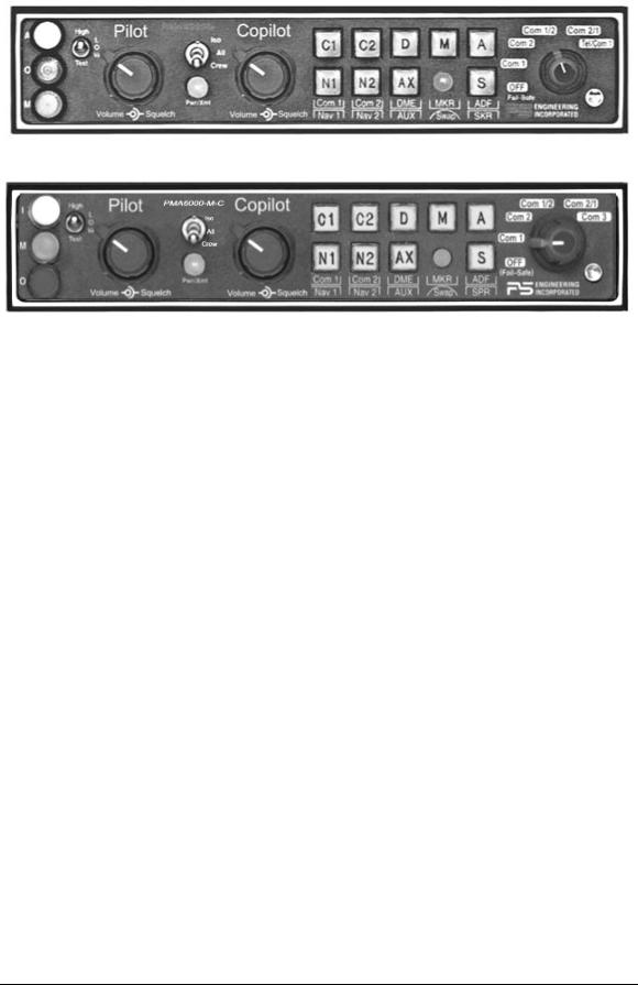
Figure 1-1 PMA6000M
Figure 1-2 PMA6000M-C
1.4APPROVAL BASIS - FAA
TSO Approval.
The PMA6000, PMA6000C and Audio Selector Panels are FAA approved under TSO C50c (Audio Amplifiers).
The PMA6000M and PMA6000M-C are FAA approved under TSO C50c and TSO C35d (Marker Beacon Receivers).
All systems comply with RTCA DO-143, DO-160b and DO-170. Operation is subject to the following conditions:
1.This device may not cause harmful interference.
2.This device must accept any interference received, including interference that may cause undesired operation.
1.5SPECIFICATIONS
GENERAL SPECIFICATION |
|
CHARACTERISTIC |
TSO COMPLIANCE: |
Marker Beacon: |
|
|
C35d, Class A |
Audio Selector/Intercom: |
|
|
C50c, Class A |
APPLICABLE DOCUMENTS: RTCA DO-160b, RTCA DO-170 and RTCA DO-143 |
|||
ENVIRONMENTAL Qualifications: |
A1D1/CAMXXXXXXXBBBBAAX |
||
Temperature Range: |
Operating: -20°C to +55°C |
Storage: -40°C to +85°C |
|
Altitude: |
Up to 50,000 feet in an non-pressurized area of the cockpit. |
||
DIMENSIONS: Height: 1.3 in. (3.3 cm) Width: 6.25 in. (16.9 cm) Depth: 6.8 in. (17.3 cm) |
|||
WEIGHT (With Rack & Connectors) : |
|
1.5 Lb. (0.68 kg.) |
|
POWER REQUIREMENTS (Including Internal Lighting): |
|
||
Voltage: |
13.75 or 27.5 VDC* |
|
|
Maximum Current: |
1 Amp (Externally protected by a 2 Amp circuit breaker.) |
||
Typical operating current: |
|
speaker off: |
350 mA |
Audio selector panel input impedance: |
speaker on: |
600 mA |
|
510 Ω |
|
||
Input Isolation: |
|
-70 dB (min.) |
|
Speaker Muting: |
|
-60 dB (min.) |
|
Speaker Output (into 4 Ω): |
|
3 Watts (min.) with no clipping |
|
Switched Receiver Inputs: |
|
8 |
|
(Com 1, Com 2, Nav 1, Nav 2, ADF, DME, MKR, AUX)
200-066-0100 |
Page 1-2 |
Rev. 1, March 2005 |

|
PS Engineering |
|
PMA6000 Series Audio Selector Panel and Intercom System |
|
Installation Manual |
Unswitched Inputs: |
2 |
(TEL Ringer, Altimeter DH) |
|
Transmitter Selections: |
5 |
(Com 1, Com 2, Com1/2, Com2/1, TEL/Com1) on PMA6000, , PMA6000M
(Com 1, Com 2, Com1/2, Com2/1, Com 3) on PMA6000C, PMA6000M-C
Speaker Impedance: |
4 Ω |
Headphone Impedance: |
150 - 1000 Ω |
Headphone Output: |
45 mW each headset with no clipping |
Microphone Impedance: |
150 - 600 Ω |
Intercom Positions: |
6 places |
Music Inputs: |
2 |
Music Muting: >50 dB "Soft Mute" when Com or intercom active. |
|
Distortion: <1% THD |
@ 45 mW into 150Ω |
Mic Freq. Response, ±3 dB: |
350 Hz - 6000 Hz |
Music Freq. Response, ±3 dB: |
200 Hz - 15 kHz |
MARKER BEACON RECEIVER: (PMA6000M, PMA6000M-S, PMA6000M-C, PMA6000M-S-C |
|
Only) |
|
Frequency: |
75 MHz Crystal Controlled |
Sensitivity: |
450 µVolts (Hard) |
Low: |
|
|
Factory adjusted to 1400µV (Soft) |
High: |
160 µVolts (Hard) |
Selectivity: |
Factory adjusted to 150µV (Soft) |
-6 dB at 110 kHz -40 dB at 120 kHz |
|
External Lamp Output: |
9.0 (+/- 0.5) VDC Positive when active, max. current 125 mA |
MM Sense: |
Active high (4.7 VDC +/- 0.5V) during Middle Marker acqui- |
|
sition, for autopilot use. |
1.6EQUIPMENT SUPPLIED
A. |
1 ea. of the following units: |
|
|
|
||
|
|
|
Model |
Part Number |
|
|
|
|
|
PMA6000 |
6000 |
|
|
|
|
|
PMA6000M |
6000M |
|
|
|
|
|
PMA6000C |
6000C |
|
|
|
|
|
PMA6000M-C |
6000MC |
|
|
B. |
PMA6000 Installation |
Tray |
430-004-0001 |
|
|
|
Kit: |
|
|
|
|||
|
Part Number |
|
Description |
Quantity |
||
|
120-425-4401 |
Top Connector, (key 2/3) |
|
|
1 |
|
|
120-425-4400 |
Bottom Connector (key 7/8) |
|
|
1 |
|
|
425-001-0001 |
Gold Plated Crimp Pins |
|
|
75 |
|
|
701-015-0015 |
15 Watt Dropping Resistor (Recommended for 28 Volt Systems) |
1 |
|||
200-066-0100 |
Page 1-3 |
Rev. 1, March 2005 |

PS Engineering
PMA6000 Series Audio Selector Panel and Intercom System
Installation Manual
1.7EQUIPMENT REQUIRED BUT NOT SUPPLIED
A.Speaker, 4 Ω
B.Headphones, mono, up to 6 as required
C.Microphones, up to 6 as required
D.Marker Antenna (75 MHz, VSWR <1:1.5, and appropriate for the airspeed)
E.Interconnect Wiring
F.Headphone Jacks (Up to 6 as required)
G.Microphone Jacks (Up to 6 as required)
H.Circuit Breaker: 1 ea. 2 amp.
I.PMA6000 Installation Manual, P/N 200-066-0100, available at www.ps-engineering.com
1.8LICENSE REQUIREMENTS
None
200-066-0100 |
Page 1-4 |
Rev. 1, March 2005 |

PS Engineering
PMA6000 Series Audio Selector Panel and Intercom System
Installation Manual
Section II -Installation
2.1GENERAL INFORMATION
2.1.1SCOPE
This section provides detailed installation and interconnect instructions for the PS Engineering PMA6000Series Audio Selector Panel/Intercom System and PMA6000M-Series Audio Selector Panel/Intercom System with internal Marker Beacon.
With the exception of the internal marker beacon receiver, the PMA6000, and PMA6000C are identical to the PMA6000M, PMA6000M-C. All units will be identified hereafter as the PMA6000, where the information applies to all.
Please read this manual carefully before beginning any installation to prevent damage and post installation problems. Installation of this equipment requires special tools and knowledge. The equipment must be installed by an appropriately rated Certified Aircraft Repair Station, in accordance with applicable regulations.
NOTE: The PMA6000-Series requires specialized knowledge equipment and tools for an effective installation. An appropriately rated Certified Aircraft Repair Station must install this equipment in accordance with applicable regulations. PS Engineering, Incorporated warranty is not valid unless the equipment is installed by an authorized PS Engineering, Incorporated dealer. Failure to follow any of the installation instructions, or installation by a non-certified individual or agency will void the warranty, and may result in an unairworthy installation.
2.2Unpacking and Preliminary Inspection
Use care when unpacking the equipment. Inspect the units and parts supplied for visible signs of shipping damage. Examine the unit for loose or broken buttons, bent knobs, etc. Verify the correct quantity of components supplied with the list in Section 1.6 (B). If any claim is to be made, save the shipping material and contact the freight carrier. Do NOT return units damaged in shipping to PS Engineering. If the unit or accessories shows any sign of external shipping damage, contact PS Engineering to arrange for a replacement. Under no circumstances attempt to install a damaged unit in an aircraft. Equipment returned to PS Engineering for any other reason should be shipped in the original PS Engineering packaging, or other UPS approved packaging.
2.3Equipment Installation Procedures
2.3.1Cooling Requirements
Forced-air cooling of the PMA6000 is not required. However the unit should be kept away from heat producing sources (i.e. defrost or heater ducts, dropping resistors, heat producing avionics) without adequate cooling air provided.
NOTICE: To reduce the amount of heat dissipated in the audio selector panel, when used in a 28 Volt aircraft, it is required that the 15 Ω, 15-Watt dropping resistor (p/n 701-015-1501) be installed in series with the power input.
If the PMA6000/M-S is installed in a 27.5 VDC aircraft system, a 15 Ω, 15 Watt dropping resistor (p/n 701-015-1501) should be installed. Failure to do so will generate unnecessary heat inside the unit and may void PS Engineering's warranty.
200-066-0100 |
Page 2-1 |
Rev. 1, March 2005 |

PS Engineering
PMA6000 Series Audio Selector Panel and Intercom System
Installation Manual
2.3.2Mounting Requirements
The PMA6000 must be rigidly mounted to the instrument panel of the aircraft structure and within view and reach of the pilot position(s). Installation must comply with FAA Advisory Circular AC 43.13-2A. The unit may be mounted in any area where adequate clearance for the unit and associated wiring bundle exist.
NOTE: The mounting hole configuration for the PMA6000 is identical to the KMA-24 Audio Selector Panel. See Appendix B
2.3.3Mounting Rack Installation
Remove the unit from the mounting tray by first removing the copilot volume and squelch knobs (the knobs are press-fit on the shaft) and then unscrew the 3/32-inch hex-head screw that is to the right of the copilot control knob shaft. Carefully slide the unit free of the tray. Set the unit aside in a safe location until needed. Install the tray using six FHP 6-32 x ½-inch screws. The audio selector panel must be supported at front and rear of the mounting tray.
2.3.4Connector Assembly
The unit connectors mate directly with the circuit boards in the PMA6000. The connectors are a Molex crimp-type, and require the use of a Molex hand crimp tool, EDP P/N 11-01-0203, CR6115B (or equiv.). The connector is mounted to the unit tray with #4-40 screws, from the inside of the tray. Ensure that proper strain relief and chafing precautions are made during wiring and installation.
2.4Cable Harness Wiring
Referring to appropriate Appendix C, D, E and F, assemble a wiring harness as required for the installation. All wires must be MIL-SPEC in accordance with current regulations. Twoand three-conductor with shield wire must be used where indicated, and be MIL-C-27500 or equivalent specification. Proper stripping, shielding and soldering technique must be used at all times. It is imperative that correct wire be used.
Refer to FAA Advisory Circular 43.13-2A for more information. Failure to use correct techniques may result in improper operation, electrical noise or unit failure. Damage caused by improper installation will void the PS Engineering warranty.
2.4.1Noise
Due to the variety and the high power of radio equipment often found in today's general aviation aircraft, there is a potential for both radiated and conducted noise interference.
The PMA6000 power supply is specifically designed to reduce conducted electrical noise on the aircraft power bus by at least 50dB. Although this is a large amount of attenuation, it may not eliminate all noise, particularly if the amplitude of noise is very high. There must be at least 13.0 VDC present at the bottom connector, pin 20, of the PMA6000 for the power supply to work in its designed regulation. Otherwise, it cannot adequately attenuate power line noise. Shielding can reduce or prevent radiated noise (i.e., beacon, electric gyros, switching power supplies, etc.) However, installation combinations can occur where interference is possible. The PMA6000s were designed in a RFI hardened chassis and have internal Electromagnetic Interference (EMI) filters on all inputs and outputs.
Ground loop noise occurs when there are two or more ground paths for the same signal (i.e., airframe and ground return wire). Large cyclic loads such as strobes, inverters, etc., can inject noise signals onto the airframe that are detected by the audio system. Follow the wiring diagram very carefully to help ensure a minimum of ground loop potential. Use only Mil Spec shielded wires (MIL-C-275000, or better). Under no circumstances combine a microphone and headphone wiring into the same shielded bundle. Always use a 2- or 3-conductor, shield wire as shown on the installation wiring diagram.
200-066-0100 |
Page 2-2 |
Rev. 1, March 2005 |
 Loading...