


9800 Martel Road
Lenoir City, TN 37772
PM3000
High-fidelity Stereo Intercom System
Part Number 11931A: 4-Place Standard
and
Part Number 11932: 6-Place with CREW Mode Operation and Installation Manual
FAA-TSO
C50c
Also includes 11933A, 11934, non-FAA TSO units
Document P/N 200-193-0005
Revision 8, Nov. 2013
PS Engineering, Inc. 2013 ©
Copyright Notice
Any reproduction or retransmittal of this publication, or any portion thereof, without the expressed written permission of PS Engineering, Inc. is strictly prohibited. For further information contact the Publications Manager at PS Engineering, Inc., 9800 Martel Road, Lenoir City, TN 37772. Phone (865) 988-9800
200-193-0005 |
Page 1 |
Rev. 8, Nov. 2013 |

Section I General Information
1.1Introduction
The PM3000 is an FAA-TSO approved, panel mounted, 4- to 6-place high-fidelity stereo intercom system (ICS). Please read this manual completely before installation to minimize the risk of damage to the unit and to become familiar with all the features.
1.2Scope
This manual contains installation and operational instructions for the following PS Engineering units:
Model |
Description |
Part Number |
|
PM3000 |
Standard 4-place system |
|
11931A |
PM3000 |
6-place system w/CREW |
11932 |
|
PM3000 |
4-place w/recorder |
|
11933A |
PM3000 |
6-place w/CREW & recorder |
11934 |
|
1.3Description
The PM3000 is a 4- or 6-place (depending on model), panel-mounted intercom with multiple volume and VOX (voice activated squelch) circuits using unified volume and squelch controls for the pilot, and copilot. Passengers volume is adjusted at the headset, after setting a master volume service adjustment on the side of the unit.
With few controls for the pilot to use, the operation of the PM3000 is very straightforward. Yet the unit outperforms its much more complicated competition. Although there is only one volume control knob, when an adjustment is made to the volume control, the crew output amplifiers are being changed simultaneously. Likewise, when the squelch control knob is adjusted, several VOX circuits are being changed at the same time. Since the system is designed to use modern stereo headsets, it is not necessary to balance the volume and squelch controls at the intercom.
A mode switch allows the pilot to select different configurations. The "ALL" mode places all headsets on a party line. In the "ISO" mode, the pilot is isolated from all others and is connected to the aircraft radio allowing un-interrupted radio communications.
The third mode, "CREW," included in part number 11932 (and 11934), allows the pilot and copilot to be separated from the passengers.
The PM3000 has an automatic fail-safe interconnect to the aircraft radios. If power is disrupted to the intercom for any reason, the pilot's headset is connected directly to the aircraft radio allowing continued radio communications in one earcup.
A 2-color LED is green when power is on and changes to red when a Push to Talk (PTT or microphone key) is pressed.
Provision for entertainment input allows the pilot, copilot and passengers the option to listen to music during flight. During intercom or aircraft radio reception, this music will automatically mute to allow communications without distraction. When the activity ceases, the SoftMute™ circuit gradually returns the music to the original listening volume. By depressing the “Mute” control (located on the Squelch knob) once, it is possible to have the music remain at a constant level, regardless of any ICS or radio traffic.
During various phases of flight, the degree of importance of the aircraft radio will vary. Because the "ISO" mode connects the pilot directly to the aircraft radio, select the "ISO" mode when the pilot must have top priority on radio transmissions.
Both pilot and copilot have transmit capabilities over the radio. The PM3000 only allows the voice of the person who presses their PTT to be transmitted over the aircraft radio. If both pilot and copilot press the PTT at the same time, the copilot will override. When either pilot or co-pilot presses PTT, all other microphones are disabled. The pilot can regain priority by switching the unit off.
1.4Approval Basis
The PM3000, part number 11931A or 11932, is FAAapproved under TSO-C50c, and RTCA, Inc. DO-214. Due to the fact that there is no TSO for the recorder function in the 11933A and 11934, these units are not TSO-approved. It is the responsibility of the installer to determine the approval basis for these units.
1.5Specifications
Input power: |
13.8 - 27.5 Volts DC |
Current : < 200 mA (Externally fused at 1 Amp) |
|
Headphone Impedance: |
150-1000 Ω (typical) |
Audio Distortion: <1.2% @ 50mW into 150 Ω load
Aircraft Radio Impedance: |
1000 Ω (typical) |
Mic Frequency Response:±3 dB, 350 Hz — 6000 Hz |
|
Music Frequency Response: ±3 dB, 200 Hz – 15 kHz |
|
Unit weight: |
12 Ounces (0.34 kg) |
Dimensions: |
|
1.25" H x 3.00" W x 5.50" D |
|
|
(3.2 x 7.6 x 14.0 cm) |
Environmental and technical qualifications: |
|
|
RTCA DO-160C/DO-214 |
Temperature |
-20º to +55º C |
Rev. 8, Nov. 2013 |
Page 2 |
200-193-0005 |
1.6 Equipment required but not supplied
A.Interconnecting cables as required (may be ordered from PS Engineering)
B.Headphones, 150 Ω stereo, as required C.Microphones, general aviation, as required D.Interconnect wiring
E.Circuit Breaker 1 Amp.
F.Optional (see page 8):
2¼” Mounting Plate without crew p/n 575-030-0007
2¼” Mounting Plate with crew p/n 575-030-0005
1.7License Requirements
None
Section II Installation
2.1General Information
The PM3000 comes with all mounting hardware and jacks for installation. Installation of the PM3000, using the hardware supplied and available wiring does not require special tools or knowledge other than described in FAA Advisory Circular 43.13-2B. It is the installer's responsibility to determine the approval basis for this installation. An FAA Form 337, or other approval may be required. See Appendix B for example of FAA Form 337.
2.2 Unpacking and preliminary inspection
The PM3000 was carefully inspected mechanically and thoroughly tested electronically before shipment. It should be free of electrical or cosmetic defect.
Upon receipt, verify that the parts kit includes the following:
PM3000 Installation Kits:
Part Number |
Description |
11931A |
11932 |
11933A |
11934 |
|
475-442-0002 |
#4-40 screws, black |
|
2 |
2 |
2 |
2 |
625-003-0001 |
Knobs (Soft Touch) |
|
2 |
2 |
2 |
2 |
575-030-0001 |
Faceplate (w/crew) |
|
|
1 |
|
1 |
575-030-0003 |
Faceplate (no crew) |
|
1 |
|
1 |
|
425-025-0010 |
25 pin connector shell |
|
1 |
1 |
1 |
1 |
425-020-5090 |
Crimp Sockets |
|
25 |
25 |
25 |
25 |
625-025-0001 |
Connector hood |
|
1 |
1 |
1 |
1 |
475-002-0002 |
Connector Thumbscrews |
1 |
1 |
1 |
1 |
|
200-193-0003 |
Operator's Guide |
|
1 |
1 |
1 |
1 |
122-001-0000 |
Drill Template |
|
1 |
1 |
1 |
1 |
475-003-0002 Insulated Shoulder Washers |
9 |
13 |
9 |
13 |
||
475-003-0001 |
Insulated Flat Washers |
|
9 |
13 |
9 |
13 |
550-001-0002 |
Stereo Headphone Jack |
|
4 |
6 |
4 |
6 |
550-001-0003 |
Microphone Jack |
|
4 |
6 |
4 |
6 |
550-008-0001 |
Music Input Jack ⅛” |
|
1 |
2 |
1 |
2 |
550-005-0001 |
Playback Plug 3.3mm |
|
|
1 |
1 |
|

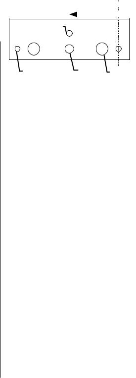
 1.200
1.200 

 1.200
1.200 


 0.838
0.838  0.838
0.838

0.250
0.325
|
2 ea. 0.125 |
0.297 |
2 ea. 0.314 |
|
|
|
NOT TO SCALE |
|
|
2.3 Equipment installation procedures
Figure 1 Hole Spacing
1.Using the template, drill six holes in the instrument panel in a location convenient to the pilot position
(s).
2.Insert the PM3000 from behind the instrument panel, aligning the holes for the knobs, LED, and switch.
3.Place the aluminum plate over the knob shafts and secure, using the two # 4-40 round head screws provided.
4.Install the knobs over the volume and squelch control shafts.
5.Complete a wiring harness in accordance with Appendix D.
2.4Cable harness wiring
To complete the installation, a wire harness must be made as shown in Appendix D.
Note:
PS Engineering can make a custom-tailored wiring harness for the installer. All harnesses use Mil-spec quality components with professional techniques, and are fully tested before shipment. Contact PS Engineering for more information, www.ps-engineering.com.
If the aircraft already has pilot headset jacks installed, you may re-use one mono set for the AUX (radio ) jacks but they should be moved to a new location to avoid confusion with the pilot's headphone jacks. In the event the intercom has to be removed for any reason, these jacks provide access to the aircraft radio system. Remove and discard copilot headset jacks if these are monaural.
To connect intercom into the aircraft audio system, parallel the appropriate set of cables from the intercom to the Auxiliary Aircraft Radio Headset Jacks. Finally, install new pilot, copilot and passenger headset jacks
200-193-0005 |
Page 3 |
Rev. 8, Nov. 2013 |

into the aircraft and connect them directly to the appropriate pins of the PM3000. See the wiring diagram for all details of the wire harness interconnect.
2.4.1 Electrical Noise Issues
WARNING: You must use individual shielded cables for the microphone and headphone jacks. Combining these two wires WILL cause loud oscillations and degrade the intercom function. The oscillation is caused by the cross-coupling between the large headphone signal and the small microphone signal. The resulting feedback is a high-pitched squeal that varies with the volume control.
Due to the variety of the radio equipment found in today's general aviation aircraft, there is the potential for both radiated and conducted noise interference. The PM3000 has a specially designed power supply to reduce conducted electrical noise on the power bus of the aircraft by at least 50dB. Although this is a very large amount of attenuation, it does not eliminate all noise when the amount is excessive. There must be at least 13.75 Volts DC present at the PM3000 for the power supply to work within its optimum regulation. Otherwise, it will not be able to attenuate noise properly.
Shielding can protect the system from radiated noise (rotating beacon, electric gyros, switching power supplies, etc.). However, installation combinations can occur where minor interference is possible. The PM3000 was designed in an interference -protected chassis and has internal filter capacitors on all input lines.
Ground loop noise occurs when there are two different return paths for the same signal, such as airframe and ground return wire. Large cyclic loads such as strobes, inverters, etc., can inject audible signals onto the airframe return path. Follow the wiring diagram very carefully to help insure a minimum of ground loop potential. Radiated signals can be a factor when low level microphone signals are bundled with current carrying power wires. Keep these cables separated.
Insulating washers are required on all microphone and headphone jacks to isolate them from aircraft ground. The use of a conductor instead of a shield for ground return eliminates these ground loop paths.
2.4.2 Power & Dimmer
The PM3000 was designed to work with 12.8 to 27.5 volt DC negative ground systems. The PM3000 must be externally protected with a one ampere (1A) circuit breaker or fuse.
[11931A & 11933A] Connect Pin 5 to the aircraft dimmer bus. This will adjust the Power/Xmit LED for
varying lighting conditions. If no connection is made, the LED will be at maximum brightness.
The unit is shipped for 14 VDC dimmer systems. For a 28 VDC aircraft dimmer system, open the PM3000 case and remove the Jumper J2.
2.4.3 Unswitched Audio Input
The PM3000, P/N 11931A & 11933A have two unswitched audio inputs available for 500Ω aviation audio sources. Pin 17 is Unswitched #1, and is also provided to the pilot in Fail-Safe Mode. Unswitched #2 input is Pin 4.
2.4.4 Sidetone
The PM3000 can be modified to produce sidetone (hearing your voice during transmit), if the aircraft radios do not produce it. Contact the PS Engineering factory for details.
2.4.5 Entertainment Input
Stereo entertainment devices can be connected to the PM3000. Install ⅛" stereo jacks convenient the pilot and passengers to connect the entertainment devices into the system. PM3000, part number 11931A has a single entertainment input. The part number 11932 will accommodate two inputs, one for the crew, and another separate input that feeds the 4 passengers in CREW mode.
It is possible to use only one entertainment device to
Use only low level output of the entertainment devices to connect to the PM3000. Maximum signal level on the input is 2-volts peak-to-peak.
DO NOT USE SPEAKER
OUTPUT LEVELS. This will cause internal damage.
provide music for both inputs in the 11932 system by connecting the output of the entertainment device in parallel to both the Music #1 and Music #2 inputs. We highly recommend, however, that you install a switch between the entertainment device and Music #1. This will give the pilot and copilot the ability to switch off music while in the CREW mode.
The music device will automatically mute when the ICS or aircraft radio becomes active. The Soft Mute™ feature slowly returns the music to full volume when the activity ceases. Pressing the Mute disable switch
If speaker levels are to be used, install an Audio Link, p/n 101PL2,
available from Crutchfield (1-800-955-3000).
Rev. 8, Nov. 2013 |
Page 4 |
200-193-0005 |
 Loading...