


Sound Quality. Sound Engineering.
9800 Martel Road
Lenoir City, TN 37772
PMA4000 TSO
Audio Selector Panel
IntelliVox™ Intercom System
Installation and Operation Manual
FAA TSO C50c
US Pat. No. 5, 903, 227 6,493,450
Also includes Non-TSO version, P/N 11941
Document P/N 200-041-0002
Revision 5, March 2007
PS Engineering, Inc. ©2007
Copyright Notice
Note: Warranty is not valid unless this product is installed by an Authorized PS Engineering or if a PS Engineering harness is purchased.
PS Engineering, Inc., 9800 Martel Road, Lenoir City, TN 37772. Phone (865) 988-9800.

PS Engineering
PMA4000 Series Audio Selector Panel and Intercom System
Installation Manual
|
Table of Contents |
|
Section I GENERAL INFORMATION...................................................................... |
1-1 |
|
1.1 |
INTRODUCTION ........................................................................................... |
1-1 |
1.2 |
SCOPE ............................................................................................................. |
1-1 |
1.3 |
EQUIPMENT DESCRIPTION ....................................................................... |
1-1 |
APPROVAL BASIS – FAATSO C50c..................................................................... |
1-2 |
|
1.4 |
SPECIFICATIONS.......................................................................................... |
1-2 |
1.5 |
EQUIPMENT SUPPLIED............................................................................... |
1-2 |
1.6 |
Optional remote volume control (P/N 250-004-0020) .................................... |
1-3 |
1.7 |
Optional 2 ¼”mounting plate kit (250-004-0005) ........................................... |
1-3 |
1.8 |
EQUIPMENT REQUIRED BUT NOT SUPPLIED ....................................... |
1-3 |
1.9 |
LICENSE REQUIREMENTS ......................................................................... |
1-3 |
Section II -Installation ................................................................................................ |
2-1 |
|
2.1 |
GENERAL INFORMATION.......................................................................... |
2-1 |
2.1.1 |
SCOPE ......................................................................................................... |
2-1 |
2.2 |
Unpacking and Preliminary Inspection............................................................ |
2-1 |
2.3 |
Equipment Installation Procedures .................................................................. |
2-1 |
2.3.1 |
Cooling Requirements ................................................................................. |
2-1 |
2.3.2 |
Mounting Requirements .............................................................................. |
2-1 |
2.3.3 |
Mounting Hole configuration ...................................................................... |
2-1 |
2.3.4 |
Connector Assembly.................................................................................... |
2-2 |
2.4 |
Cable Harness Wiring...................................................................................... |
2-2 |
2.4.1 |
Noise ............................................................................................................ |
2-2 |
2.4.2 |
Entertainment Input ..................................................................................... |
2-3 |
2.4.3 |
Radio Push-to-Talk ...................................................................................... |
2-3 |
2.4.4 Power and 28 VDC Dropping Resistor........................................................ |
2-4 |
|
2.4.5 |
Backlighting................................................................................................. |
2-4 |
2.4.6 |
Intercom ....................................................................................................... |
2-4 |
2.4.7 Digital recorder (11941 only) ...................................................................... |
2-4 |
|
2.5 |
Adjustments ..................................................................................................... |
2-5 |
2.6 |
Panel Installation.............................................................................................. |
2-5 |
2.7 |
Post Installation Checkout ............................................................................... |
2-5 |
2.7.1 |
Operational Checkout .................................................................................. |
2-6 |
2.8 |
Final Inspection................................................................................................ |
2-6 |
Section III OPERATION ......................................................................................... |
3-1 |
|
3.1 |
SCOPE ............................................................................................................. |
3-1 |
3.2 |
Audio Selector ................................................................................................. |
3-1 |
3.2.1 Intercom Mode Selector Switch .................................................................. |
3-1 |
|
3.2.2 |
Speaker Amplifier........................................................................................ |
3-2 |
3.3 |
Mic Selector Switch......................................................................................... |
3-2 |
3.3.1 |
Volume Control ........................................................................................... |
3-2 |
3.3.2 |
VOX-Squelch Control ................................................................................. |
3-2 |
3.3.3 |
Intercom Modes ........................................................................................... |
3-3 |
3.3.4 Push to talk intercom mode.......................................................................... |
3-4 |
|
200-041-0002 |
Page ii |
Rev 5, March 2007 |

PS Engineering
PMA4000 Series Audio Selector Panel and Intercom System
Installation Manual
3.3.5 Internal Recorder System (Part number 11941, only) ................................. |
3-4 |
|
Section IVWarranty and Service ........................................................................... |
4-1 |
|
4.1 |
Warranty .......................................................................................................... |
4-1 |
4.2 |
Factory Service ................................................................................................ |
4-1 |
Appendix A External PTT Hook Up.......................................................................... |
A |
|
Appendix B- Installation Drawing and Connector Layout....................................... |
B |
|
Appendix C Unit Connector Wiring ........................................................................... |
C |
|
Appendix D -Instructions for FAA Form 337 and Continuing Airworthiness....... |
D |
|
Appendix E RTCA DO160D (EUROCAE ED-14) Environmental Qualification |
||
Form |
................................................................................................................................... |
E |
|
Table of Figures |
|
Figure .......................................................................................................1-1 PMA4000 |
1-1 |
|
Figure .......................................................................................................3-1 PMA4000 |
3-1 |
|
Figure ...................................................................................................3-2 Mic Selector |
3-2 |
|
Figure ..........................................................................................6-1- Hole Configuration |
A |
|
Figure ..............................................6-2 Hole Configuration to avoid rectangular cutouts |
A |
|
Figure ..............................................................................................6-3 Connector Layout |
B |
|
Figure ..........................................................................................6-4 Installation Diagram |
B |
|
|
Table of Tables |
|
Table .............................................................................3-1 Mic Muff ™ Part Numbers |
3-3 |
|
Table ...............................................................................................3-1 Intercom Modes |
3-4 |
|
Revision History
Rev. |
By |
Date |
Description of Change |
3 |
Picou |
January 2006 |
Updated section 2.4.4 for power |
|
|
|
wires, allow smaller gage. |
4 |
Picou |
March2006 |
Added information for 11941 |
|
|
|
|
5 |
Picou |
March2007 |
Clarified mounting dimensions |
|
|
|
|
200-041-0002 |
Page iii |
Rev 5, March 2007 |
PS Engineering
PMA4000 Series Audio Selector Panel and Intercom System
Installation Manual
Section I GENERAL INFORMATION
1.1INTRODUCTION
The PMA4000 TSO Audio Selector Panel is a right-sized solution for the audio switching needs of light aircraft. By combining basic audio selector panel, with PS Engineering’s revolutionary IntelliVox® intercom, the aircraft owner can have audio panel functionality without an investment in panel space.
Before installing and/or using this product, please read this manual completely. This will ensure that you will take full advantage of all the advanced features.
1.2SCOPE
This manual provides detailed installation and operation instructions for the PS Engineering PMA4000 TSO Audio Selector Panel/Intercom Systems. This includes the following unit:
Model |
Description |
Part Number |
PMA4000 TSO |
Audio Selector Panel |
11942 |
PMA4000-NON TSO |
Audio Selector Panel w/IRS |
11941 |
1.3EQUIPMENT DESCRIPTION
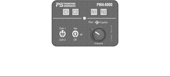
The PMA4000-series is a state of the art audio isolation amplifier and audio selector that contains an automatic voice activated (VOX) intercom system. It can switch two transceivers (Com 1, Com 2) and two receivers (Nav 1, Nav 2) In addition, there are four unswitched inputs, for additional audio requirements. Push buttons select the receiver audio source provided to the headphones. A SPR push-on switch on the volume control allows the user to listen to the receiver(s) selected on the cabin speaker. Except for the unswitched inputs, all speaker audio is muted during transmit. A toggle switch selects one of the two transceivers for the pilot and copilot positions in transmit.
A fail-safe mode connects the pilot headphone and microphone to COM 1 if power is removed for any reason, or if the Com Selector switch is in the “Off” position.
A 4-station voice activated (IntelliVox™) intercom is included in the PMA4000. Pilot isolate and ALL modes, a mono music input with "Soft Mute." A dual concentric knob pair controls pilot volume and copilot/passenger intercom volume.
Figure 1-1 PMA4000
200-041-0002 |
Page 1-1 |
Rev 5, March 2007 |

PS Engineering
PMA4000 Series Audio Selector Panel and Intercom System
Installation Manual
APPROVAL BASIS – FAATSO C50c
The PMA4000 p/n 11942, Audio Selector Panels are FAA approved under TSO C50c (Audio Amplifiers).
All systems comply with relevant portions of EUROCAE ED-14C/DO-160D (Environmental Conditions and Test Procedures for Airborne Equipment), ED12B/DO-178B (Software Considerations for Airborne Equipment) and ED- 18/DO-214 (Audio Systems Characteristics and Minimum Operational Performance Standards for Aircraft Audio Systems).
Operation is subject to the following conditions:
1.This device may not cause harmful interference.
2.This device must accept any interference received, including interference that may cause undesired
operation.
The part number 11941 unit is NOT FAA Approved.
1.4 |
SPECIFICATIONS |
|
|
|
|
ENVIRONMENTAL Qualifications: |
|
B1CABSRXXXXXXABBBBTMXXE2XXX |
|
|
Temperature Range: |
|
-20ºC to +55ºC |
|
|
Operating: |
|
||
|
Storage |
|
-40ºC to +85ºC |
|
|
Altitude: |
|
Up to 25,000 feet in an unpressurized area of the cock- |
|
|
|
|
|
pit. |
|
Audio Selector/Intercom: |
|
C50c, Class A |
|
|
APPLICABLE DOCUMENTS: |
|
RTCA/DO-214, RTCA/DO-160D |
|
|
DIMENSIONS: |
|
Height: 1.35 in. (3.4 cm) Width: 2.40 in. (6.1 cm) |
|
|
|
|
|
Depth: 6.50 in. (16.5 cm) behind panel |
|
WEIGHT (With Connectors): |
|
12.4 oz. (0.35 kg) |
|
|
Voltage: |
|
11 to 33 VDC (28 Volt w/dropping resistor) |
|
|
Maximum Current: |
|
0.25 Amp (Externally protected by a 3 Amp circuit |
|
|
|
|
|
breaker.) |
|
Typical operating current: |
|
100 mA |
|
|
Speaker off: |
|
||
|
Speaker on, 28V, full radio volume |
|
250 mA |
|
|
|
|
Audio Selector |
Specifications |
|
Audio selector panel input impedance: |
|
510 Ω |
|
|
Input Isolation: |
|
-60 dB (min.) |
|
|
Speaker Muting: |
|
-60 dB (min.) |
|
|
Speaker Output (into 4 Ω) with no clipping |
2 Watts (min.) |
||
|
14 VDC: |
|
||
|
28 VDC: |
|
8 Watts (min.) |
|
|
Receiver Inputs: |
|
4 (Com 1, Com 2, Nav 1, Nav 2) |
|
|
Unswitched Inputs: |
|
4 (examples: ADF, DME. GPS WPT, Marker, Autopi- |
|
|
|
|
|
lot Disconnect, Altimeter DH) |
|
Transmitter Selections: |
|
2 (Com 1, Com 2) |
|
|
Speaker Impedance: |
|
4 Ω |
|
|
Headphone Impedance: |
|
150 – 1000 Ω |
|
|
Headphone Output: |
|
30 mW each headset, with < 10% THD into 150Ω |
|
|
Microphone Impedance: |
|
150 - 600 Ω |
|
|
|
|
Intercom |
Specifications |
|
Intercom Positions: |
|
4 places (with individual IntelliVox® circuits) |
|
|
Music Input: |
|
1 (Monaural) |
|
|
Music Muting: |
|
>-30 dB "Soft Mute" |
|
|
Distortion: |
|
<1% THD @ 30 mW into 150Ω |
|
|
Mic Freq. Response,±3 dB: |
|
300 Hz - 6000 Hz |
|
|
Music Freq. Response,± 3 dB: |
|
100 Hz - 18kHz |
|
1.5EQUIPMENT SUPPLIED
A.1 ea. of the following units:
200-041-0002 |
Page 1-2 |
Rev 5, March 2007 |

PS Engineering
PMA4000 Series Audio Selector Panel and Intercom System
Installation Manual
Unit |
Part Number |
PMA4000 TSO |
11942 |
PMA4000 w/IRS |
11941 |
B.PMA4000 Installation Kit: 250-0041-0001
Part Number |
Description |
Quan |
575-004-0005 |
Faceplate (Square) |
1 |
475-632-0006 |
Mounting Screws6-32X3/8”Phil-Pan Black |
2 |
625-002-0001 |
Knob, outer |
1 |
625-002-0004 |
Knob, inner |
1 |
625-010-0002 |
Knob insert pointer |
1 |
425-025-0009 |
Connector Shell Male |
1 |
425-025-0010 |
Connector Shell Female |
1 |
425-020-5089 |
Crimp Pin, male |
25 |
425-020-5090 |
Crimp Socket, female |
25 |
701-015-1501 |
Dropping Resistor, 15 Ω, 15 Watt, (required in 28 |
1 |
|
VDC installation) |
|
475-002-0002 |
Connector Thumbscrews |
4 |
625-025-0001 |
Connector Hood |
2 |
430-400-0028 |
Mounting Shim– 0.028 in |
1 |
430-400-0050 |
Mounting Shim –0.050 in. |
1 |
200-041-0002 |
Operator's and Installation Manual |
1 |
1.6Optional remote volume control (P/N 250-004-0020)
This kit contains:
1 ea. 10KΩ Potentiometer P/N 675-020-0103
1 ea. knob, Black 1/4" Shaft w/Set Screw P/N 625-020-0005
1.7Optional 2 ¼”mounting plate kit (250-004-0005)
This kit contains:
1 ea. 2 ¼” Mounting plate for instrument hole mounting, P/N 575-004-0001 1 ea. Mounting Shim, 430-400-0090
1.8EQUIPMENT REQUIRED BUT NOT SUPPLIED
A.Speaker, 4 Ω
B.Headphones, 150 Ω mono, up to 4 as required
C.Microphones, up to 4 as required
D.Interconnect Wiring
E.Contact Crimping Tool, AMP 601966-1 (or MS22520 equiv.), with Positioning Tool 601966-5
F.Headphone Jacks (As Required)
G.Microphone Jacks (As Required)
H.Circuit Breaker: 1 ea. 3 amp.
1.9LICENSE REQUIREMENTS
None
200-041-0002 |
Page 1-3 |
Rev 5, March 2007 |

PS Engineering
PMA4000 Series Audio Selector Panel and Intercom System
Installation Manual
Section II -Installation
2.1GENERAL INFORMATION
2.1.1 SCOPE
This section provides detailed installation and interconnect instructions for the PS Engineering PMA4000-TSO Series Audio Selector Panel/Intercom System, and PMA4000 w/IRS.
Please read this manual carefully before beginning any installation to prevent damage and post installation problems. Installation of this equipment requires special tools and knowledge. The equipment must be installed by an appropriately rated Certified Aircraft Repair Station, in accordance with applicable regulations.
2.2Unpacking and Preliminary Inspection
Use care when unpacking the equipment. Inspect the units and parts supplied for visible signs of shipping damage. Examine the unit for loose or broken buttons, bent knobs, etc. Verify the correct quantity of components supplied with the list in Section 1.6 (B). If any claim is to be made, save the shipping material and contact the freight carrier. Do NOT return units damaged in shipping to PS Engineering. If the unit or accessories shows any sign of external shipping damage, contact PS Engineering to arrange for a replacement. Under no circumstances attempt to install a damaged unit in an aircraft. Equipment returned to PS Engineering for any other reason should be shipped in the original PS Engineering packaging, or other UPS approved packaging.
2.3Equipment Installation Procedures
2.3.1 Cooling Requirements
Forced-air cooling of the PMA4000 is not required. However the unit should be kept away from heat producing sources (i.e. defrost or heater ducts, dropping resistors, heat producing avionics) without adequate cooling air provided.
2.3.2 Mounting Requirements
The PMA4000 must be rigidly mounted to the instrument panel of the aircraft structure and within view and reach of the pilot position(s). Installation must comply with FAA Advisory Circular AC 43.13-2A. The unit may be mounted in any area where adequate clearance for the unit and associated wiring bundle exist.
2.3.3 Mounting Hole configuration
For instrument panel mounting, make openings in the panel according to the templates and drawing supplied. Depending on the instrument panel thickness, you may elect to use the shim supplied for the best button depth and mechanical contact. See Appendix B for mounting hole layout.
200-041-0002 |
Page 2-1 |
Rev 5, March 2007 |
 Loading...