

Page 1
Sound Quality. Sound Engineering
Sound Quality. Sound Engineering
.
.
PMA7000M-S CAP Operation
PS Engineering, Inc.
PS Engineering, Inc.
Prepared by Gary Picou
Lenoir City TN (423) 988-9800
GUYICS@aol.com
1
Page 2
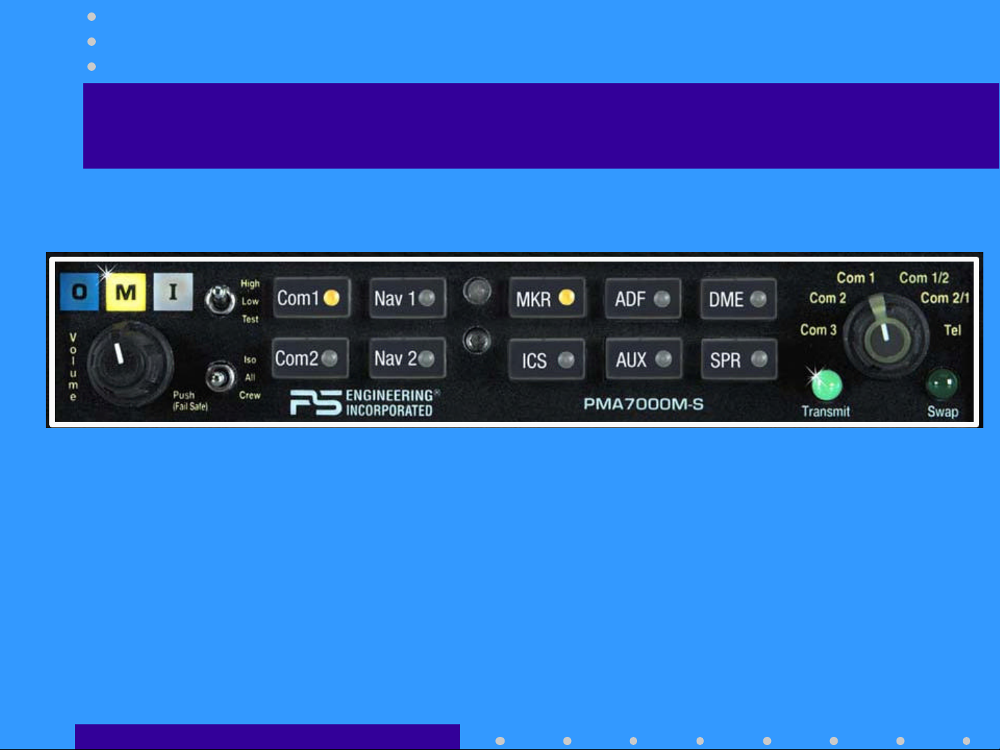
PMA7000M-S Standard Versions
Standard Version PMA7000M-S
2
Page 3
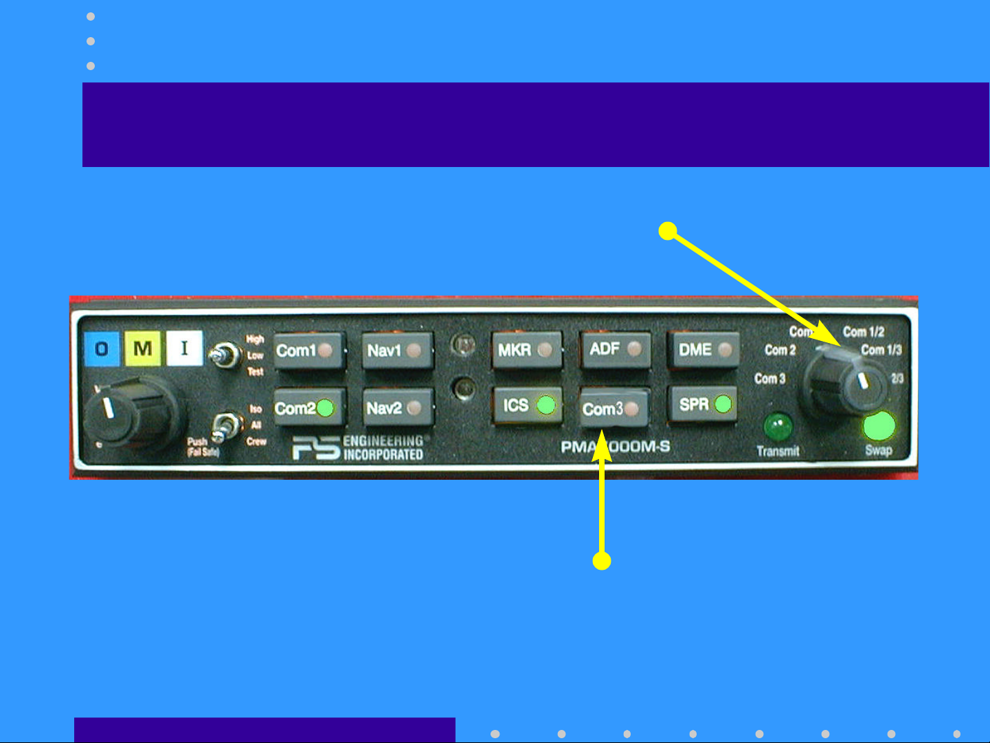
PMA7000M-S ‘Civil Air Patrol’
Added Split Com Modes
Black buttons, silver trim
Com 3 Button
3
Page 4
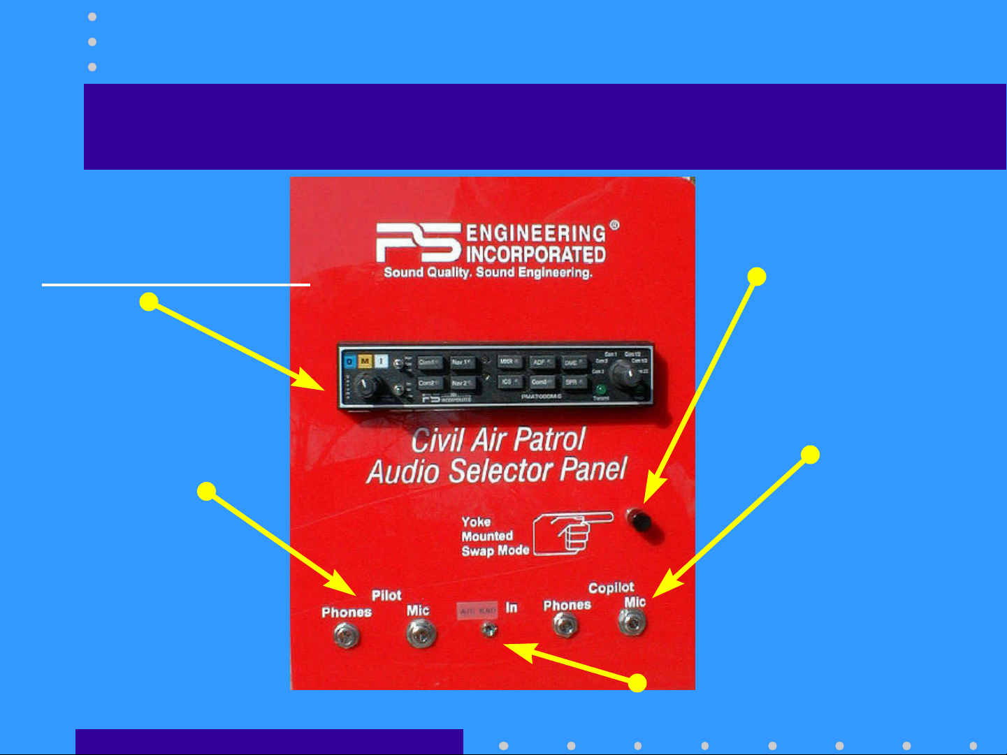
PMA7000MS-CAP Operational Training
Demo PMA7000MS
(NOT AIRWORTHY)
Pilot Headset
Com SWAP button
Copilot Headset
Only pilot and copilot positions operate
Aircraft Radio Input (Com 1 Only)
4
Page 5

The PMA7000M-S Features:
• Full-function audio control panel:
– 3 coms, 2 navs, ADF, DME
– 3 light marker beacon receiver
• PS Engineering’s innovative:
– Com1/Com2 /Com 3 Sp l it Mode for cockpit
resource management
– Swap Mode for ease of operation
– 6-pole filtered mic circuits for less noise, better
clarity
5
Page 6

Revolutionary Intercom
• All, ISO and Crew modes
• 6-Place
– Dual, independent auxiliary inputs
Stereo intercom
Stereo
• Introducing IntelliVox™
– Six INDEPENDENT mic sampling circuits
– Constantly monitoring and adjusting VOX level
– Field proven in helicopters and high noise cockpits
– NO MANUAL ADJUSTMENT -EVER-
6
Page 7

Basic Operation
• Push Volume Control to switch on
– Unless in Com 3 mode, at least one com LED
will light.
– Backlighting comes on
• Push Volume control to switch off
– Fail Safe mode places pilot on Com 1
– Copilot/passengers have no audio
• Intercom operation: Just talk
7
Page 8
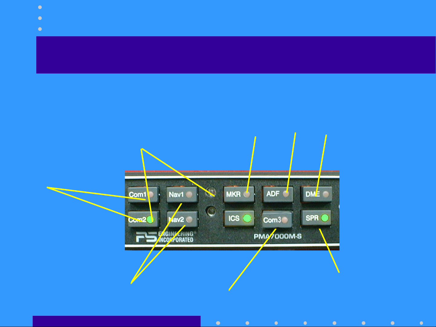
PMA7000M-S Operation
Audio Selection
Audio Selection
Com receivers
Nav Receivers
Bright LED
Auto dimmed
Marker, ADF, DME
Cabin Speaker
Com 3 Audio Select
8
Page 9

Audio Selection
• COM 1 and 2 are momentary buttons
– Receive audio always follows the Mic selector
– Push button to add other com receive audio
• Com 3 audio is latched
• Push Com 1, Com 2 and /or Com 3 to monitor
• Receiver buttons latch
– Positive indication of the selected audio
– LEDs also annunciate audio sources selected
• SPR button places all selected audio
in cabin speaker
9
Page 10

Transmitter Selection
SPLIT MODE
Pilot and Copilot on Com 1
Pilot and Copilot on Com 2
Pilot and Copilot on Com 3
Transmit Indicator
Pilot on Com 1
Copilot on Com 2
SPLIT MODE
Pilot on Com 1
Copilot on Com 3
SPLIT MODE
Pilot on Com 2
Copilot on Com 3
Yoke Mounted SWAP
reverses the indicated selection
10
Page 11

Transmitter Selection
• Rotary switch controls transmitter selection
– You can’t transmit without listening to the receiver.
– Selector has the same order as the panel -top to bottom, 1-3
• Com 1, Com 2, Com 3
– Pilot and copilot can both transmit on same radio.
– Pilot has PTT priority
– Only person pushing PTT is heard over radio
• Com 1/2
– Pilot transmit and receive on Com 1
– Copilot transmit and receive on Com 2
• Com 2/1
– Vice versa
11
Page 12

CAP Transmitter Combinations
No Swap
No Swap
Com 1/3
Normal Swap
Mic Se-
lector
Com 1 Com 1 Com 1 Com 2 Com 2
Com 2 Com 2 Com 2 Com 1 Com 1
Com 3 Com 3 Com 3
Com1/2 Com 1 Com 2 Com 2 Com 1
Com 2/3 Com 2 Com 3 Com 3 Com 2
If the Com 3 button is pushed in a Com 3 split mode, the pilot
will also hear Com 3 audio, but no transmit.
Pilot Copilot Pilot Copilot
Com 1 Com 3 Com 3 Com 1
Pushing SWAP again, or moving MIC Selector cancels swap
12
Page 13

Who’s talking now?
• Com 1 or Com 2 annunciator flashes
to show which radio is transmitting.
• Pilot hears selected receive audio in
split mode
• If Com 3 is selected he will hear it in
split, and can elect to monitor Com 3
receptions
13
Page 14

Three transmit positions
• Through an external switch some
aircraft can be configured to
exchange the copilot connection
with the observer position.
• Gives observer position any radio
transmit ability.
• Copilot becomes passenger
14
Page 15

Split Mode Limitations
• Two comms transmitting
in close proximity may
bleed over.
• Depends on:
– Emission (AM/FM=Better)
– Frequency (> Difference
=Better)
– Transmit Power (lower=Better)
– Antenna location
(Farther=Better)
15
Page 16

Intercom Functions
Intercom
Volume
CW=Increase
Mode Select
Dual Independent Auxiliary Inputs
Front and back are separated.
IntelliVox™
IntelliVox™
Squelch
ISO Pilot in command
ISO
All Everybody tunes in
All
Crew Front vs. back
Crew
ICS Button
Activates Intercom in Split Modes
Aux muting Control
16
Page 17

Intercom Functions
• Volume Control
– Only affects the intercom level.
• Not , auxiliary not radio.
– Intercom volume control for pilot and copilot only
• Rear passengers are fixed volume.
• Stereo headsets have individual volume controls, can be
adjusted with screwdriver.
• Push on/Push off switch
– Fail-Safe mode connects pilot headset to Com 1 if
unit off, or power removed.
17
Page 18

Intercom Modes
• ISO
– Pilot only hears
radios
– Copilot and
passengers have
intercom
– Copilot hears
Aux 1
– Passengers hear
Aux 2
• ALL
– Everybody
hears
everything
– Radios
– Intercom
– Pilot and
copilot hear
Aux 1
– Passengers hear
Aux 2
• Crew
– Pilot & Copilot
hear radios
– Pilot and
copilot have
separate
intercom
– Passengers have
intercom, no
radios.
– Crew- Aux 1
– Passengers-
Aux 2
18
Page 19

IntelliVox ™
Revolutionary microprocessor system
••Revolutionary
– No manual control
– 6-independent circuits
– constant monitoring
• Just speak normally
– Position microphone close to your lips
– Use a microphone muff
– Avoid direct drafts into microphone
– More noise the better it works
19
Page 20

Intercom Entertainment
• Aux source #1 feeds pilot and
copilot headset.
– is muted whenever the intercom or radios are
active.
• Push “ICS” button to disable muting
of the auxiliary inputs
• Aux 2 feeds rear 4 seats.
– External switch in rear of aircraft to control
Aux 2 muting
ICS
20
Page 21

Marker Beacon Receiver
3-lights:
Marker Modes
High Sense
High
Low Sense
Low
Outer,
O
Middle and IInner
M
Audio Selection
Test Lamps and receiver
Test
21
Page 22

Marker Beacon Operation
• Receiver always on.
• Select MKR for receiver audio.
• High sense until tone acquired.
– Select low sense if desired to precise station
crossing indication.
• Test function for lamps and audio
circuits.
22
Page 23

PTT ICS
• Push to talk intercom (PTT)
– For very noisy conditions
– Only for pilot and copilot positions
– Must install ICS PTT button at each position
• PTT-Enable select switch on panel
– Forces IntelliVox squelch closed
– Then use ICS PTT to be heard on intercom
23
Page 24

Night time dimming
• The backlighting is adjusted by the
aircraft dimmer OR
– Set at a fixed level at installation.
• Annunciators and Marker lamps
controlled by photocell on unit.
– The photodetector has a delay for smooth
transition
24
Page 25

ProSupport Customer Care
• Questions or Comments or Problems :
– Call PS Engineering at (423) 988-9800
8:00 am to 5:00 p.m. Eastern time.
– FAX: (423) 988-6619 any time
– email: GUYICS@aol.com or
intercoms@ps-engineering.com
• 3-Year warranty
– Replacement for first 12 months
– Repair for following 24 months
25
Page 26

From all of us at PS Engineering. . .
THANK YOU !
THANK YOU !
THANK YOU !
THANK YOU !
26
 Loading...