

Page 1

9800 Martel Road
Lenoir City, TN 37772
www.ps-engineering.com
PMA450A
Document P/N 200-450-0100
Revision 5 September 2017
Audio Selector Panel with Marker Beacon Receiver
High-fidelity Stereo Intercom, USB Charging Port
System Installation and Operation Manual
FAA- TSO C139a, C35d, C71
Patented under one or more of the following;
No. 4,941,187; 5,903,227; 6,160,496 and 6,493,450, 7,391,877
PS Engineering, Inc. 2017 ©
Copyright Notice
Any reproduction or retransmittal of this publication, or any portion thereof, without the expressed written permission of PS Engineering, Inc. is strictly prohibited. For further information contact the Publications Manager at PS Engineering, Inc., 9800
Martel Road, Lenoir City, TN 37772. Phone (865) 988-9800, email contact@ps-engineering.com.
In certified aircraft, warranty is not valid unless this product is installed by an
Authorized PS Engineering dealer.
Page 2

Table of Contents
Section I – GENERAL INFORMATION 1-1
1.1 INTRODUCTION ............................................................................................................................................................................................. 1-1
1.2 SCOPE................................................................................................................................................................................................................ 1-1
1.3 EQUIPMENT DESCRIPTION ......................................................................................................................................................................... 1-1
1.4 APPROVAL BASIS ........................................................................................................................................................................................... 1-2
1.1.1 LIMITATIONS ................................................................................................................................... 1-2
1.5 SPECIFICATIONS ........................................................................................................................................................................................... 1-2
1.6 EQUIPMENT SUPPLIED ................................................................................................................................................................................ 1-3
1.8 LICENSE REQUIREMENTS ........................................................................................................................................................................... 1-4
Section II - INSTALLATION .............................................. 2-1
2.1 GENERAL INFORMATION............................................................................................................................................................................ 2-1
2.1.1 SCOPE ........................................................................................................................................... 2-1
2.1.2 CERTIFICATION REQUIREMENTS ..................................................................................................... 2-1
2.2 UNPACKING AND PRELIMINARY INSPECTION ...................................................................................................................................................... 2-1
2.3 EQUIPMENT INSTALLATION PROCEDURES .......................................................................................................................................................... 2-1
2.3.1 COOLING REQUIREMENTS ............................................................................................................... 2-1
2.3.2 MOUNTING REQUIREMENTS ............................................................................................................ 2-1
2.3.3 AUDIO PANEL MOUNTING RACK INSTALLATION ............................................................................ 2-2
2.3.4 AUDIO PANEL TRAY AND CONNECTOR ASSEMBLY ......................................................................... 2-2
2.4 CABLE HARNESS WIRING .................................................................................................................................................................................... 2-2
2.4.1 ELECTRICAL NOISE ......................................................................................................................... 2-2
2.4.2 EXISTING GMA340 AND PMA8000 INSTALLATIONS ...................................................................... 2-3
2.4.3 POWER ............................................................................................................................................ 2-4
2.4.4 COMMUNICATIONS PUSH-TO-TALK ................................................................................................. 2-4
2.4.5 AUDIO PANEL INTERFACE ............................................................................................................... 2-4
2.4.6 TRANSMIT INTERLOCK .................................................................................................................... 2-4
2.4.7 BACKLIGHTING ............................................................................................................................... 2-4
2.4.8 UNSWITCHED INPUTS ...................................................................................................................... 2-5
2.4.9 "SWAP" MODE ................................................................................................................................ 2-5
2.4.10 PUBLIC ADDRESS MODE ............................................................................................................... 2-5
2.4.11 COM RECEIVE ACTIVE OUTPUT (J1, PIN 24) ................................................................................ 2-6
2.4.12 WIRED TELEPHONE/SATELLITE COMMUNICATION INPUT ............................................................. 2-6
2.4.13 MUSIC INPUTS ............................................................................................................................... 2-6
2.4.14 PLAYBACK BUTTON INSTALLATION .............................................................................................. 2-7
2.5 MARKER BEACON INSTALLATION (050-450-0101, -0102 ONLY) ........................................................................................................................ 2-7
2.5.1 MARKER ANTENNA INSTALLATION ................................................................................................. 2-7
2.5.2 EXTERNAL MARKER LIGHTS ........................................................................................................... 2-7
2.5.3 MIDDLE MARKER SENSE ................................................................................................................. 2-7
2.6 USER ADJUSTMENTS ............................................................................................................................................................................................ 2-7
2.6.1 ADJUST SCREEN .............................................................................................................................. 2-8
2.6.2 RENAME “SWITCHED” INPUTS ........................................................................................................ 2-8
2.6.3 VOLUME SETUP ............................................................................................................................... 2-9
2.6.4 BLUETOOTH® MENU ....................................................................................................................... 2-9
2.7 COMMUNICATIONS ANTENNA INSTALLATION NOTES ....................................................................................................................................... 2-10
2.8 PMA450A PIN ASSIGNMENTS ........................................................................................................................................................................... 2-11
2.9 WIRING CHECKOUT .......................................................................................................................................................................................... 2-12
2.10 UNIT INSTALLATION .......................................................................................................................................................................................... 2-12
2.11 OPERATIONAL CHECKOUT ................................................................................................................................................................................ 2-12
2.11.1 REQUIRED TEST EQUIPMENT ...................................................................................................... 2-12
2.11.2 AUDIO PANEL TEST .................................................................................................................... 2-12
2.11.3 MARKER CHECKOUT (050-450-0101, -0102 ONLY) ................................................................... 2-13
2.11.4 BLUETOOTH CHECKOUT ............................................................................................................. 2-13
2.11.5 INTERNAL RECORDER CHECKOUT............................................................................................... 2-13
2.12 FINAL INSPECTION ............................................................................................................................................................................................ 2-13
Section III OPERATION .................................................. 3-1
3.1 SCOPE................................................................................................................................................................................................................ 3-1
3.2 POWER AND FAIL SAFE (1) .................................................................................................................................................................................. 3-1
3.3 DISPLAY MENU SELECTION (6) ........................................................................................................................................................................... 3-1
3.4 COMMUNICATIONS TRANSMIT (XMT) SELECTION (2) ....................................................................................................................................... 3-2
3.4.1 SPLIT MODE .................................................................................................................................... 3-2
3.5 COM AUDIO SELECTOR (3) ................................................................................................................................................................................ 3-2
3.5.1 SWAP MODE (SWITCH FROM COM 1 TO COM 2 REMOTELY) ............................................................ 3-3
3.5.2 INTELLIAUDIO® DIMENSIONAL AUDIO .......................................................................................... 3-3
Page 3

PS Engineering
PMA450A Audio Selector Panel and Intercom System
Installation and Operator’s Manual
200-450-0100 Page ii Rev. 5, September 2017
3.5.3 COM MONITOR MODE ..................................................................................................................... 3-3
3.5.4 NAVAID SELECTION (4) ................................................................................................................... 3-4
3.6 SPEAKER AMPLIFIER (7) ..................................................................................................................................................................................... 3-4
3.6.1 PUBLIC ADDRESS FUNCTION ........................................................................................................... 3-4
3.7 MARKER BEACON OPERATION (9) (UNIT PART NUMBERS 050-450-0101, -0102 ONLY) ....................................................................................... 3-5
3.7.1 MARKER BEACON SENSITIVITY ...................................................................................................... 3-5
3.8 INTERCOM OPERATION (8) .................................................................................................................................................................................. 3-6
3.8.1 INTELLIVOX® INTERCOM VOX-SQUELCH ....................................................................................... 3-6
3.8.2 INTERCOM VOLUME CONTROL (1) .................................................................................................. 3-6
3.8.3 INTERCOM MODES (8) ..................................................................................................................... 3-7
3.9 MUSIC CONTROL, DISTRIBUTION AND MUTING .................................................................................................................................................. 3-8
3.9.1 MUSIC MUTING ............................................................................................................................... 3-9
3.9.2 MUSIC VOLUME .............................................................................................................................. 3-9
3.9.3 MUSIC IN PILOT ISO MODE ........................................................................................................... 3-10
3.10 BLUETOOTH® CONNECTION .............................................................................................................................................................................. 3-10
3.10.1 PAIRING AND UN-PAIRING BLUETOOTH DEVICES ........................................................................ 3-10
3.11 BLUETOOTH® TELEPHONE MODE .................................................................................................................................................................... 3-11
3.11.1 BLUETOOTH RESET ..................................................................................................................... 3-11
3.11.2 BLUETOOTH PIN ......................................................................................................................... 3-12
3.11.3 BLUETOOTH CELLULAR TELEPHONE SIDETONE ........................................................................... 3-12
3.12 WIRED SATCOM/CELL PHONE INPUT ................................................................................................................................................................ 3-12
3.13 INTERNAL RECORDER AND PLAYBACK .............................................................................................................................................................. 3-13
3.14 PS STREAMER OPERATION ............................................................................................................................................................................... 3-13
3.14.1 PAIRING ...................................................................................................................................... 3-14
3.14.2 STREAMER ON/OFF ...................................................................................................................... 3-14
3.14.3 SOURCE SELECTION .................................................................................................................... 3-14
3.15 TIMER FUNCTIONS (SERIAL NUMBER E45A1373 AND UP ONLY)......................................................................................................................... 3-1
3.15.1 SETTING THE TIMER ...................................................................................................................... 3-1
3.15.2 COUNT DOWN ............................................................................................................................... 3-1
3.15.3 COUNT UP ..................................................................................................................................... 3-1
3.16 USER SETUP MENUS ............................................................................................................................................................................................. 3-1
3.16.1 ADJUST SCREEN (OLED ADJUSTMENT) ........................................................................................ 3-2
3.16.2 REMEMBERING MUSIC MUTE MODE ............................................................................................. 3-3
3.16.3 RENAME “SWITCHED” INPUTS ...................................................................................................... 3-3
3.16.4 BLUETOOTH SETUP ....................................................................................................................... 3-3
3.16.5 VOLUME SETUP ............................................................................................................................ 3-4
3.17 USB CHARGING PORT (10) ................................................................................................................................................................................. 3-4
Section IV – Warranty and Service .......................................... 4-1
4.1 WARRANTY ......................................................................................................................................................................................................... 4-1
4.2 FACTORY SERVICE .............................................................................................................................................................................................. 4-1
Appendix A – PMA450A Installation Drawings .................................................................... A
Appendix B – J1 Connector Interconnect ........................................................................... B
Appendix C – J2 Connector Interconnect ........................................................................... C
Appendix D – Instructions for FAA Form 337 and continuing airworthiness .................... D
8.1 INSTRUCTIONS FOR FAA FORM 337, AUDIO PANELS ............................................................................................................................................ D
8.2 INSTRUCTIONS FOR CONTINUING AIRWORTHINESS, AUDIO SYSTEM .................................................................................................................... D
Appendix E – RTCA DO160G Environmental Qualification Form .................................... E
Rev
Date
Change
New
July 2016
Release of manual for PMA450A
1
August 2016
Update for connector type and production release
2
September 2016
Update installation kit part numbers
3
October 2016
Add Copilot/Passenger Alternate ICS Mode, S /N B45A1174 and above
4
July 2017
Added Timer Function, S/N E45A1373 and above
5
September 2017
Modified User Interface, S/N G45A
Page 4

PS Engineering
PMA450A Audio Selector Panel and Intercom System
Installation and Operator’s Manual
200-450-0100 Page 1-1 Rev. 5, September 2017
Section I – GENERAL INFORMATION
1.1 INTRODUCTION
The PMA450A represents a revolutionary step in cockpit audio control and intercommunications utility.
IntelliAudio®, using the USAF patented technology, provides True Dimensional Sound, helping pilots to
more easily discern from simultaneous radio receptions. Our patented IntelliVox® design, front panel USB
power jack, and pilot programmable configurations, marks this panel as the next level of audio control. The
unit is designed for outstanding ergonomics and visually defined mode annunciation and selection.
Before installing and/or using this product, please read this manual completely. This will ensure that you will
take full advantage of all the advanced features in the PMA450A.
1.2 SCOPE
This manual provides detailed installation and operation instructions for the PS Engineering PMA450Aseries of Audio Selector Panel/Intercom Systems. This includes the following units:
Model
Description
Part Number
PMA450A
Digital Stereo Audio Selector Panel with Marker Beacon,
USB Charging port
050-450-0101
PMA450A
Digital Stereo Audio Selector Panel with Marker Beacon,
USB Charging port and PS Streamer Module
050-450-0102
PMA450A
Digital Stereo Audio Selector Panel with USB Charging
port without Marker Beacon
050-450-0201
1.3 EQUIPMENT DESCRIPTION
The PMA450A is a state-of-the-art audio isolation amplifier and audio selector that contains an automatic
voice activated (VOX) intercom system and integral marker beacon receiver. It can switch two transceivers
(Com 1, Com 2) and six receivers (Nav 1, Nav 2, MKR, and three additional inputs which can be individually
labeled, for use with ADF, DME, AUX, etc.).
Warning: Use of non-aviation approved cellular telephone equipment may be prohibited by FCC regulation.
PS Engineering is not responsible for unauthorized airborne use of cellular telephones.
For airborne use, the PMA450A must be interfaced with an approved system.
There are four unswitched inputs, available for traffic or EGPWS, autopilot disconnect, and/or radar altimeter
warning.
Pushbuttons select the receiver audio source provided to the headphones. A SPR button allows the user to
listen to the receiver(s) selected on the cabin speaker. Except for the unswitched inputs, all speaker audio is
muted during transmit. Unswitched inputs 1& 2 are always presented to the aircraft speaker. Unswitched
input 3 & 4 will be presented to the speaker when the front panel SPR push button has been selected.
Pushbutton switches select one of the communication transceivers for the pilot and copilot position, and allow
radio transmission. In "Split Mode" the PMA450A has the ability to allow the pilot to transmit on Com 1
while the copilot can transmit on Com 2. A fail-safe mode connects the pilot headphone and microphone to
COM 1 if power is removed for any reason, or if the power switch is placed in the Off (Fail-safe) position.
Unswitched input #1 is also provided to the pilot headphone (left side headset ear cup) in fail-safe
A six-station voice activated (VOX) intercom is included in the PMA450A. This system has PS Engineer-
ing’s patented IntelliVox® circuitry that eliminates manual adjustments. The intercom system incorporates
pilot isolate, all and crew modes, two independent stereo music inputs with "SoftMute™". Intercom volume
control is through two concentric front panel knobs and a pushbutton intercom mode switch. The small volume knob controls the intercom level for the pilot and copilot, while the large knob controls the passenger
intercom volume. Intercom squelch is automatic.
Page 5

PS Engineering
PMA450A Audio Selector Panel and Intercom System
Installation and Operator’s Manual
200-450-0100 Page 1-2 Rev. 5, September 2017
A, 75 MHz Marker Beacon receiver and 3-light indicator is integrated in the PMA450A (050-450-0101 only).
This provides the necessary Marker Beacon lights and audio indications necessary for that portion of an
Instrument Landing System (ILS) approach. A pushbutton labeled MKR allows the pilot select audio on as
well as test and mute modes. Marker high sensitivity is also controlled by this button.
The front panel USB-type connector is available for charging devices, such as iPad or cell phones. Up to 10
Watts are available. This connector does NOT provide any data interface.
In the PMA450A, a Bluetooth® wireless interface is available for wireless telephone and music connection.
The PMA450A, Part Number 050-890-0913, Serial Number XXXX and above contain a timer function, with
on-screen control and aural alerts
1.4 APPROVAL BASIS
FAA TSO Approval
The PMA450A-series Audio Selector Panels are FAA approved under TSO C139A (Audio Amplifiers) TSO
C35d (Marker Beacon Receivers) and C71 (DC Power Supplies)
All systems comply with relevant portions of EUROCAE RTCA MPS WG No. 7/70, DO-143 and (Marker
Beacon Receivers), ED-14C/DO-160G (Environmental Conditions and Test Procedures for Airborne Equipment), ED12B/DO-178B, Level D (Software Considerations for Airborne Equipment) and ED- 18/DO-214A
(Audio Systems Characteristics and Minimum Operational Performance Standards for Aircraft Audio Systems).
1.1.1 Limitations
This article meets the minimum performance and quality control standards required by a technical standard
order (TSO). Installation of this article requires separate approval.
Refer to Advisory Circular 20-41A for information on TSO installation approval.
Operation is subject to the following conditions:
This device may not cause harmful interference.
This device must accept any interference received, including interference that may cause undesired operation.
1.5 SPECIFICATIONS
TSO COMPLIANCE
Marker Beacon:
FAA TSO C35d, Class A
Audio Selector/Intercom:
FAA TSO C139a, Class 1a
DC Charging Jack
FAA TSO C71
APPLICABLE DOCUMENTS:
RTCA/DO-214A RTCA/DO-143 RTCA/DO160G
RTCA/DO-178C, DO-254
ENVIRONMENTAL Qualifications:
A1D1CABSMXXXXXXZBABATBXXE2XXX
Operating Temperature Range:
-15º C to 55ºC
Altitude:
Up to 35,000 feet in an non-pressurized area
DIMENSIONS:
Height: 1.3 in. (3.3 cm) Width: 6.25 in. (15.9 cm)
Depth behind panel 7.15 in. (18.16 cm)
WEIGHT
PMA450A Unit
Rack with connectors
1.34 lb. (0.61 kg)
0.51 lb. (0.24 kg)
POWER REQUIREMENTS (Including Internal Lighting):
Voltage:
11 to 33 VDC
Maximum Current:
3.5 Amp (Externally protected by a 5A pull-type
breaker)
Page 6

PS Engineering
PMA450A Audio Selector Panel and Intercom System
Installation and Operator’s Manual
200-450-0100 Page 1-3 Rev. 5, September 2017
Audio Selector Specifications
Audio selector panel input impedance:
510
Input Isolation:
-60 dB (min.)
Speaker Muting:
-60 dB (min.)
Speaker Output (into 4 ) with no clipping
14 VDC:
28 VDC:
3 Watts (min.)
10 Watts (min.)
Receiver Inputs:
7 (Com 1, Com 2, Nav 1, Nav 2, 2 ea. Additional Switched
Inputs available or ADF, DME, etc.)
Unswitched Inputs:
4
Transmitter Selections:
3 (Com 1, Com 2, Com1/2)
Speaker Impedance:
4
Headphone Impedance:
150 – 1000
Headphone Output:
30 mW each headset, no clipping <.5% THD typical
Microphone Impedance:
150 - 600
Bluetooth Radio
Class 3, FCC ID QOQWT32AE
Intercom Specifications
Intercom Positions:
6 places (with individual IntelliVox® circuits)
Music Inputs:
2, (Independent, Stereo)
Music Muting:
>-30 dB "Soft Mute" when Com or intercom active.
Distortion:
<1% THD @ 30 mW into 150
Mic Freq. Response, 3 dB:
300 Hz - 6000 Hz
Music Freq. Response, 3 dB:
10 Hz – 26 kHz
MARKER BEACON RECEIVER (-0100 only)
Frequency:
75 MHz Crystal Controlled
Sensitivity:
Low:
High:
Capable of: (preset at factory for field application)
1000 Volts (Hard) (360 to 570 V soft)
200 Volts (Hard) (130 to 200 V soft)
Selectivity:
-6 dB at ±10 kHz
-40 dB at ±120 kHz
External Lamp Output:
7.5 (±4 VDC unloaded, at maximum brightness) VDC positive when active, max. current 125 mA
MM Sense:
Active high (4.5 ± 1.0VDC)
USB Charging Port
Available Current
3.5A (15W Maximum) output, short circuit and over-currentrotected
Voltage
5 VDC
1.6 EQUIPMENT SUPPLIED
1 ea. of the following units:
Model
Description
Part Number
PMA450A
PMA450A Digital Audio Panel with Marker, Stereo Intercom,
USB-C Charging jack, and Bluetooth connectivity
050-450-0101
PMA450A
Same as above, without Marker Beacon capability
050-450-0201
PMA450A
Digital Audio Panel with Marker, Stereo Intercom, USB-C Charging jack, and Bluetooth connectivity, includes PS Streamer Module (P/N 011-894-0000)
050-450-0102
PMA450A
Same as above, without Marker Beacon capability
050-450-0203
Page 7

PS Engineering
PMA450A Audio Selector Panel and Intercom System
Installation and Operator’s Manual
200-450-0100 Page 1-4 Rev. 5, September 2017
PMA450 Installation Kit: 250-890-0000
Description
Quantity
Part
Number
Installation rack assembly
1
430-890-0040
Rack back plate
1
430-890-0050
44-pin connector kit
2
120-891-2045-
Backshell, connector
2
625-025-2465
Backshell Retainer
2
431-881-0100
4 40 X 7/16 screw w/nylon patch
4
475-440-0007
4 40 X 3/8 screw w/nylon patch
4
475-440-1038
4-40 x ¼” screw with lock washer
2
475-440-0001
Solder Lug
2
475-009-0001
Cable Clamp
1
625-001-0002
#6-32 x ½” Flat head Philips screw
6
475-632-0012
#6-32 Clip Nut
6
475-630-0002
EQUIPMENT REQUIRED BUT NOT SUPPLIED
a. Circuit Breaker: 1 ea; 5 amp PULL TYPE REQUIRED for PMA450A
b. Speaker, 4 as desired
c. Headphone Jacks (Stereo, as Required)
d. Microphone Jacks (as Required)
e. Headphones, 150 (Stereo), up to 6 as required
f. Microphones, up to 6 as required
g. Marker Antenna (75 MHz, VSWR <1:1.5, and appropriate for the airspeed) (-0101 Only)
h. Interconnect Wiring
1.8 LICENSE REQUIREMENTS
None
PMA450A Bluetooth™ Radio approval:
FCC ID: QOQWT32AE
Industry Canada ID: 5123A-BGTWT32AE
CE EMC Directive 89/336/EEC as amended by Directives 92/31/EEC and 93/68/EEC
NOTE
Unauthorized use of unapproved cellular telephone devices in aircraft is subject to FCC enforcement action, which may include a $10,000 fine per incident.
FCC Regulation 47 CFR § 22.925 Prohibition on airborne operation of cellular telephones.
Cellular telephones installed in or carried aboard airplanes, balloons or any other type of aircraft must not
be operated while such aircraft are airborne (not touching the ground). When any aircraft leaves the ground,
all cellular telephones on board that aircraft must be turned off.
PS Engineering, Inc. does not endorse using unapproved cellular telephone equipment in flight, and takes
no responsibility for the user’s action.
PS Engineering does not guarantee compatibility with personal cellular telephones.
Page 8

PS Engineering
PMA450A Audio Selector Panel and Intercom System
Installation and Operator’s Manual
200-450-0100 Page 2-1 Rev. 5, September 2017
Section II - INSTALLATION
2.1 GENERAL INFORMATION
2.1.1 SCOPE
This section provides detailed installation and interconnection instructions for the PS Engineering PMA450A
Audio Selector Panel/Intercom/ with internal Marker Beacon.
Please read this manual carefully before beginning any installation to prevent damage and post-installation
problems.
Installation of this equipment requires special tools, test equipment (refer to §2.12.1) and installer knowledge
as required by 14 CFR 65.81 (b).
2.1.2 Certification Requirements
NOTE
The PMA450A requires specialized knowledge and tools for an effective installation. An appropriately
rated Certified Aircraft Repair Station must install this equipment in accordance with applicable regulations. PS Engineering, Incorporated warranty is not valid unless the equipment is installed by an authorized
PS Engineering, Incorporated dealer.
Failure to follow any of the installation instructions, or installation by a non-certified individual or agency
will void the warranty, and may result in an unairworthy installation.
This article meets the minimum performance and quality control standards required by a technical standard
order (TSO). Installation of this article requires separate approval. Refer to AC 20-41A for information
regarding Substitute TSO Aircraft Equipment.
2.2 Unpacking and Preliminary Inspection
Use care when unpacking the equipment. Inspect the units and parts supplied for visible signs of shipping
damage. Examine the unit for loose or broken buttons, bent knobs, etc. Verify the correct quantity of components supplied with the list in §1.6. If any claim is to be made, save the shipping material and contact the
freight carrier. Do NOT return units damaged in shipping to PS Engineering. If the unit or accessories show
any sign of external shipping damage, contact PS Engineering to arrange for a replacement. Under no circumstances attempt to install a damaged unit in an aircraft. Equipment returned to PS Engineering for any
other reason should be shipped in the original PS Engineering packaging, or other UPS approved packaging.
2.3 Equipment Installation Procedures
2.3.1 Cooling Requirements
Forced air-cooling of the PMA450A is not required. However, the units should be kept away from heat
producing sources (i.e. defrost or heater ducts, dropping resistors, heat producing avionics) without adequate
cooling air provided.
2.3.2 Mounting Requirements
The PMA450A must be rigidly mounted to the instrument panel of the aircraft structure, within view and
reach of the pilot position(s). Installation must comply with FAA Advisory Circular AC 43.13-2B, or other
FAA-approved aircraft technical data. The unit may be mounted in any area where adequate clearance for
the unit and associated wiring bundle exist.
To prevent noise, avoid installing the unit close to high current devices or systems with high-voltage pulse
type outputs, such as DME or transponders. Avoid running the interconnecting bundles near any high current
wires.
Page 9

PS Engineering
PMA450A Audio Selector Panel and Intercom System
Installation and Operator’s Manual
200-450-0100 Page 2-2 Rev. 5, September 2017
2.3.3 Audio Panel Mounting Rack Installation
Remove the unit from the mounting tray by unscrewing the 3/32" hex-head screw that is in the center of the
unit. Use caution to avoid hitting the photo-detector lens. Carefully slide the unit free of the tray. Set the unit
aside in a safe location until needed. Install the tray using six clip nuts (475-630-0002), and six FHP 6-32 x
½" screws (475-632-0012). The audio selector panel must be supported at front and rear of the mounting
tray.
2.3.4 Audio Panel Tray and Connector Assembly
The rack connectors mate with two 44-pin connectors in the PMA450A. The connectors are a sub-miniature
crimp-type, and require the use a hand crimp tool, from table below (or equiv.). The connectors are mounted
to the tray back plate with #4-40 screws (475-440-1038), from the inside of the tray.
Assemble the connector back shell as shown in figure 2-1.
Ensure that proper strain relief and chafing precautions are made during wiring and installation, using the
cable clamp (625-001-0002).
Two grounding lugs are provided, which may be attached to the rear mounting plate with 2 ea #4-40 x ¼”
screws with captivated lock washers. These provide a convenient location to connect the shield ground terminations.
Manufacturer
Crimping Tool
Positioner
Extraction tool
AMP
601966-1
601966-6
91067-1
Daniels
AFM8
K42
M24308-1
ITT-Cannon
995-0001-584
995-0001-739
91067-1
Table 2-1 Connector Pin crimping tools
2.4 Cable Harness Wiring
Referring to the appropriate Appendix, assemble a wiring harness as required for the installation. All wires
must be MIL-SPEC in accordance with current regulations. Two- and three-conductor shielded wire must be
used where indicated, and be MIL-C-27500 or equivalent specification. Proper stripping, shielding and soldering technique must be used at all times. It is imperative that correct wire be used.
Refer to FAA Advisory Circular 43.13-2B for more information. Failure to use correct techniques may result
in improper operation, electrical noise or unit failure. Damage caused by improper installation will void the
PS Engineering warranty.
2.4.1 Electrical Noise
Due to the variety and the high power of radio equipment often found in today's general aviation aircraft,
there is a potential for both radiated and conducted noise interference.
The PMA450A power supply is specifically designed to reduce conducted electrical noise on the aircraft
power bus by at least 50dB. Although this is a large amount of attenuation, it may not eliminate all noise,
particularly if the amplitude of noise is very high. There must be at least 13.8 VDC present at the connector,
J2 pins 8 & 9, of the PMA450A for the power supply to work in its designed regulation. Otherwise, it cannot
adequately attenuate power line noise. Shielding can reduce or prevent radiated noise (i.e., beacon, electric
gyros, switching power supplies, etc.) However, installation combinations can occur where interference is
possible. The PMA450A was designed in a RFI hardened chassis and has internal Electromagnetic Interference (EMI) filters on all inputs and outputs.
Ground loop noise occurs when there are two or more ground paths for the same signal (i.e., airframe and
ground return wire). Large cyclic loads such as strobes, inverters, etc., can inject noise signals onto the airframe that are detected by the audio system. Follow the wiring diagram very carefully to help ensure a minimum of ground loop potential. Use only Mil Spec shielded wires (MIL-C-275000, or better). Under no
circumstances combine a microphone and headphone wiring into the same shielded bundle. Always use a 2or 3-conductor, shield wire as shown on the installation-wiring diagram.
The shields can be daisy-chained together, and then connected to the ground lugs mounted on the back plate
shown in Appendix B.
Page 10
PS Engineering
PMA450A Audio Selector Panel and Intercom System
Installation and Operator’s Manual
200-450-0100 Page 2-3 Rev. 5, September 2017
Radiated signals can be a factor when low level microphone signals are "bundled" with current carrying
power wires. Keep these cables physically separated. It is very important that you use insulated washers to
isolate the ground return path from the airframe to all headphone and microphone jacks.
2.4.1.1 Music Inputs and Noise
PMA450A units utilize a differential input to help prevent noise from entering the music system. This feature
is usually transparent to the installer; however, it is important that the appropriate music signal and ground
connections are made directly to the dedicated music signal and ground inputs on the PMA450A. The power
for IFE and audio panel should be a common bus.
If a music jack instead of a music source is installed for Music 1 or 2, we recommend grounding the jack to
airframe ground.
NOISE NOTE
Adding a high-performance audio control system, particularly in conjunction with high-performance active
noise canceling headsets, cannot improve on older avionics that were designed for cabin-speaker use. PS
Engineering makes no claim that the audio panel will provide a noise-free audio quality under all installation
conditions, particularly with older avionics.
2.4.2 Existing GMA340 and PMA8000 Installations
If the installation replaces a GMA340 or any of the PMA8000 series, no changes are necessary as long as the
existing installation meets the requirements. All existing functions of the GMA340 as afforded by the
PMA450A will become instantly available. However, if the previous installation had three COMs, the
PMA450A will not support the third COM; the PMA450A handles only two COM transceivers. The
PMA8000C will support three COMs.
2.4.2.1 Differences with GMA340 connector
Connector
Pin
GMA340 Function
PMA450A Function
J1 3 COM 3
TEL Audio Hi
J1 4 COM 3
TEL Lo
J1 5 COM 3
TEL Mic Audio Hi
J1 6 COM 3
No Connection
J1
16
MASQ Inhibit
No Connection
J1
23
COM 3 Speaker Load
AUX Audio Input
J1
24
COM 3 Speaker Load
CNX80 Inhibit
J1
25
COM Speaker Load
No Connection
J1
26
COM Speaker Load
No Connection
J1
27
COM Speaker Load
No Connection
J1
28
COM Speaker Load
No Connection
J1
29
No Connection
Unswitched #3
J2
15
High Music Gain Select
Unswitched #4
J2
17
8Ω Speaker Select
No Connection
J2
18
No Connection
Aux Enable Output
J2
19
Tone Enable
PA Enable
J2
29
Failsafe warn
No Connection
J2
30
Com TX Mute
No Connection
Table 2-2 GMA340–PMA450A connector differences
Installations where the external marker outputs are connected to a Sandel 3308 Navigation Display will require additional loading resistors. Refer to the Sandel installation data for more information.
Page 11

PS Engineering
PMA450A Audio Selector Panel and Intercom System
Installation and Operator’s Manual
200-450-0100 Page 2-4 Rev. 5, September 2017
2.4.3 Power
The PMA450A is compatible with both 14 and 28 Volt DC systems. A five (5) Amp circuit breaker is required for all installations. Power and ground wires should be #22AWG connect power to J2 Pins 8 and 9.
Connect airframe ground to J2 Pin 10 and 11 only.
2.4.4 Communications Push-to-Talk
An important part of the installation is the PTT (Push-To-Talk) switches that allow the use of your aircraft
communications radio for transmissions. There are three typical configurations that can be used. Select the
case that best fits the installation. Only the person who presses their PTT switch will be heard over the radio.
If the pilot and copilot both use the PTT, the only pilot position has access to the radio. The pilot position
will have PTT control regardless of the mic selector switch or copilot PTT when the PMA450A is in the
OFF/EMG mode.
CASE I: PTT is built into both pilot and copilot yokes.
CASE II: PTT is in pilot yoke only. This configuration requires a modified external PTT switch plugged into
the copilot's microphone jack (See Appendix A). When the copilot's PTT is pressed, the intercom switches
the microphone audio from pilot to copilot mic.
CASE III: No built in PTT. This requires two built in PTTs to be installed, or modified external PTT switches
to be used. Modify external PTT as required. See Appendix A.
2.4.5 Audio Panel interface
The PMA450A is designed to interface with standard aircraft avionics, and presents a 510 receiver impedance. For best results, a twisted-shielded cable is recommended from the avionics audio source to the audio
panel, with the shield grounded at the audio panel end.
Some avionics do not provide a separate audio low, and may introduce additional electrical noise into the
system. For best results, connect the audio low from the audio panel to the radio ground, using one conductor
of the twisted-shielded cable.
2.4.5.1 Speaker Load
The PMA450A contains a speaker amplifier. The PMA450A does not contain any resistive speaker loads.
Some older aviation radios units with internal speaker amplifiers, require a resistive load if their speaker
amplifier is not used. If needed, connect the radio speaker output from the transceiver to a 16, 3W resistor
in the harness.
2.4.5.2 Installation with Monaural Headsets
Not recommended, because the benefit of IntelliAudio is lost. However, if desired, the PMA450A can be
installed monaurally by using the LEFT audio connections only (left side contains Fail-Safe audio). Do NOT
short left and right together.
NOTE: Mono headsets that short the tip and ring (i.e. older models) may introduce audio distortion
when used. Modern, stereo headsets are recommended in all positions.
2.4.6 Transmit Interlock
Some communications transceivers use a transmit-interlock system. To fully utilize the Split Mode feature,
this function must be disabled. Consult the radio manufacturer's installation manual.
2.4.7 Backlighting
The PMA450A has an automatic dimming of the pushbutton annunciation LEDs and marker lamps controlled
by a photocell. Control of the unit nomenclature backlighting is through the aircraft avionics dimmer For 14
V aircraft, connect J2 Pins 6 and 7 to the aircraft dimmer bus, and pin 5 to ground. For 28-volt systems,
connect pin 7 to the aircraft dimmer, and pins 5 and 6 to ground.
If an external dimmer control is not used, a constant back light illumination can be established for nighttime
viewing. Pin 6 or 7 (depending on system voltage) must be tied to power (J2, pin 8 or 9) for the back lighting
Page 12

PS Engineering
PMA450A Audio Selector Panel and Intercom System
Installation and Operator’s Manual
200-450-0100 Page 2-5 Rev. 5, September 2017
system to work. The photocell mounted in the unit face will automatically adjust the intensity of the pushbutton annunciator LEDs.
2.4.8 Unswitched inputs
J1, pins 31 (Unsw 1), 44 (Unsw 2) 29 (Unsw 3) and J2 pin 15 (Unsw 4) are unswitched, unmuted (by transmitter keying), inputs.
These inputs are presented to the pilot and copilot regardless of the audio configuration, and will always mute
the crew entertainment inputs. These 510Ω inputs can be used for altimeter DH audio, GPS waypoint audio,
autopilot disconnect tones, or any other critical audio signal.
Unswitched #1 is always presented to the speaker, plus to the crew headphones, and is available to the pilot
in fail-safe (off) mode.
Unswitched 1 & 2 are always presented to the speaker, plus to the crew headphones.
*Unswitched 3 and 4 inputs are always presented to the crew headphones but presented to the aircraft speaker
only when the speaker is selected.
Unswitched
Input
Hear in
Fail Safe
Hear in
Crew Headset
Hear in SPR
Adjustable at installation
1
Yes
Yes
Yes
No
2
No
Yes
Yes
No
3
No
Yes
When SPR Se-
lected
Yes
4
No
Yes
When SPR Se-
lected
Yes
Table 2-3 Unswitched inputs
The audio low for unswitched #4 (J2, pin 15) should be connected to a convenient audio low. However, this
should NOT be connected to Music Low.
NOTE
Inputs 1 and 2 are fixed (1:1), and any audio level adjustments must be made at the input source. Unswitched
#3 and #4 can be adjusted at installation. Refer to Adjustments §2.7.
2.4.8.1 Additional unswitched inputs
If necessary, unused switched inputs can be converted to unswitched inputs. Contact PS Engineering for
more information.
2.4.9 "Swap" Mode
When a momentary, normally open, push-button switch is connected between pin 20 on the J2 connector and
aircraft ground, the user can switch between Com 1 and 2 by depressing this switch without having to turn
the mic selector switch. This yoke-mounted switch eliminates the need to remove your hands from the yoke
to change transceivers. The transfer of TX indication from Com 1 to Com 2 shows that the swap has been
initiated; there is no dedicated swap indicator.
2.4.9.1 Remote ICS mode control
A long press of the remote SWAP switch (>1 second) will change the intercom mode, in order
All/CREW/ISO/All, as shown on the intercom mode indicator on the PMA450A.
2.4.10 Public Address Mode
By holding the N1 pushbutton for more than one (1) seconds, the PMA450A will be placed into public
address (PA) mode. In this mode, the pilot will be talking over the cockpit speaker when he presses his PTT
switch. Copilot will still continue on the selected COM radio.
The display will include PA & SPR on the right side, and change to PUBLIC ADDRESS when the pilot’s
PTT is pressed.
Page 13

PS Engineering
PMA450A Audio Selector Panel and Intercom System
Installation and Operator’s Manual
200-450-0100 Page 2-6 Rev. 5, September 2017
2.4.10.1 PA Active Output (J2, Pin 19)
PA Active Out is a discrete output on J2 Pin 19 which will go low when PA mode is selected, providing a
logic level that can be used to incorporate a speaker-switching scheme. This 50 mA circuit (10Ω Z) can
control a switching means such as a small relay or other switching means that can transfer the speaker output
amplifier from the cockpit speaker to drive another cabin speaker. If the PA mode is used with a microphone
in proximity to an active cockpit speaker, feedback might result.
2.4.10.2 PA Mute (J2, Pin 12)
Pin 12 of J2 is a TTL logic output that is pulled low during PTT operation. This is used to control external
public address or external entertainment systems and prevent feedback during radio transmission.
2.4.11 COM Receive Active Output (J1, Pin 24)
Pin 24 on the J1 connector (and PA Mute Pin 12 on J2) should be connected to Apollo CNX80 for audio
message prioritization. The output is logic low when radio audio is present. Refer to CNX80 installation
manual for details.
2.4.12 Wired Telephone/Satellite Communication input
The PMA450A can accommodate a wired cell phone interface on J1 Pins 3, 4 and 5.
Hold the N2 button for 1 second to activate the Telephone screen. Telephone volume and sidetone can be
controlled from this screen.
Both Bluetooth and wired Telephone and be accommodated, however, only ONE can be active at a time.
See Appendix C and D for intercom connection configurations. It is critical to the proper operation of this
system to have this connector wiring made in accordance with these diagrams. Use 2- and 3-conductor, MILspec cable as shown. Connect the shields at the audio panel end only, and tie to the audio low inputs as shown.
NOTE
The intercom harness can be custom made by PS Engineering, Inc. Simply call the factory or www.ps-engi-
neering.com to obtain a wire harness work sheet. The harness will be made to your specifications and fully
functionally tested. Harness can be ordered with jack, or without the intercom jacks installed, for easier wire
routing through the aircraft.
2.4.13 Music Inputs
The PMA450A has three INDEPENDENT music inputs. Music input number 1 is J2 pins 23 (left channel)
and 24 (right channel), with respect to pin 25, and Music number 2 is connected to 26 (left channel), 27 (right
channel), with respect to 28, plus Bluetooth® connectivity to stream music from a paired device.
NO TE
Use t he lo w le ve l outp ut of any add it io na l Musi c devic e to c on ne ct t o the aud io pa ne l.
Maximum si gn al l ev el i s 3 V AC p- p. D O NO T u se a s pe aker -le ve l outp ut, thi s will
cause i nter nal dama ge in the audio pan el.
CAUTION
Local oscillators and internal signals from Music equipment can cause undesired interference with other
aircraft systems. Before takeoff, operate the entertainment devices to determine if there is any adverse effect
within the aircraft systems. If any unusual operation is noted in flight, immediately switch off the entertainment devices.
All additional entertainment devices must be switched off for both takeoff and landing.
2.4.13.1 Passenger Mute (J2 Pin 13 & 14)
Connecting J2 pin 13 to pin 14 (or ground) through a SPST switch places the Passenger music source into
the Karaoke Mode. In this mode, incoming music and intercom conversation will not mute the music for the
passengers’ intercom net. This is useful for passenger-area control of the music muting, and overrides the
PMA450A Music Mute menu-controlled setting.
Page 14

PS Engineering
PMA450A Audio Selector Panel and Intercom System
Installation and Operator’s Manual
200-450-0100 Page 2-7 Rev. 5, September 2017
2.4.14 Playback button Installation
The pilot and copilot can hear the aircraft radio playback.
The Internal Recorder System can be played back from the front panel by pressing the RCV button of the
radio selected for transmission.
Or a remote, momentary, normally open (NO) push button switch may be installed if desired to activate the
Recording System playback. This switch can be located anywhere in cockpit convenient to the pilot's reach.
The NO switch should be connected to pin 22 of J2 of the PMA450A, and ground. When installed, this button
will act as in §3.13.
2.4.14.1 Cell phone Sidetone
The PMA450A provides cellular telephone sidetone (the user’s voice fed back to the headset). Some cell
phones provide sidetone, and may have poor audio quality if both sources are combined. The cell phone
sidetone is adjustable in the Bluetooth® operation screen See §2.6.
2.5 Marker Beacon Installation (050-450-0101, -0102 Only)
2.5.1 Marker Antenna Installation
A marker beacon antenna, appropriate to the type and speed of the aircraft, is required (not included). Refer
to aircraft and antenna manufacturer's installation instructions, as well as AC43.13-2B (or later revision),
Chapter 3, for information on proper antenna installation techniques. The marker beacon antenna must be
mounted on the bottom of the aircraft.
2.5.2 External Marker Lights
For installations that require external marker beacon lights, there are three outputs that can drive 12-Volt
lamps only. The external output lamps are driven high (typically +7.0 VDC 4.0 VDC unloaded, at MAX
brightness) when active. Maximum source current per lamp is 125 mA. Voltage varies with photocell dimming.
2.5.3 Middle Marker Sense
A Middle Marker Sense output signal is available from the PMA450A to certain flight control systems. This
function will not operate during the test mode. This output will go to +4.5 VDC ( 1.0 VDC) when a valid
Middle Marker signal is received. This output is J1, pin 39.
2.6 User Adjustments
To access the user adjustment menus, turn the PMA450A off and then back on. While the version screen is
displayed, push and hold the bottom line-select button (there is an indicator bar in the display indicating that
a menu is available). This places the unit into the “User Configurable Mode – home screen”. This allows
adjustment for:
OLED Screen Adjustment
Rename Switched Inputs
Bluetooth menus
Mute mode recall
Note: in this mode, the audio panel functions will be inoperative
Page 15

PS Engineering
PMA450A Audio Selector Panel and Intercom System
Installation and Operator’s Manual
200-450-0100 Page 2-8 Rev. 5, September 2017
2.6.1 Adjust Screen
The first items are adjustments to the OLED, allowing the installer or user to tailor the backlight intensity to
suit the cockpit conditions, and set the time period before the menus revert to the “home” screen.
2.6.1.1 Brightness
Adjusting the Brightness level requires selecting either of the two line select buttons
and then turning the inner knob. Counter
clockwise to lower the number (level of
Brightness) and clockwise to increase the
number (level of Brightness).
To change the display:
Press the line select for the de-
sired item
Turn the small, inner knob to change the brightness as desired.
OLED will change in real time while adjustments are made.
It will stay in this screen until the menu times out and returns to the adjustment home screen.
2.6.1.2 Display Timeout
This is a feature that allows the end user to adjust how quickly the screen menu timeout (revert to main
menu).
NOTE: A long press (> 1 second) will also back up one menu level.
This allows adjustment of the timeout screen and can be configured from 1 second to 30 seconds when turning
the inner knob.
For a user that is unfamiliar with the product, this will give them enough time to learn the system. After being
familiar then the user can speed up the timeout screen as needed.
It will stay in this screen until the menu times out and returns to the adjustment home screen.
To exit the home screen and return to normal operation, turn the PMA450A off, and back on again.
2.6.2 Rename “Switched” Inputs
The system is factory set to default as ADF, & DME as shown.
The three inputs are from top to bottom:
1. Switched input #1 J1, Pin 7 wrt Pin 8 (Default ADF)
2. Switched input #2 J1, Pin 21 wrt Pin 22 (Default DME)
3. NOTE: In PMA 450 -0200 (No Marker) Switched #1, or #2 can be renamed to MKR for a remote
input.
The customer will have access to rename. Maximum 9 letters per line and A thru a and 0 thru 9 will be
available.
Press the line select for desired input.
Turn the large outer knob to select the letter to change. A cursor appears under the active letter po-
sition.
Turn the small, inner knob to increment or decrement the letter.
You can select 9 alphanumeric digits.
To add a blank space:
o Blank spaces can’t be added to the end of a string, but you can add a temporary character
and go back and change it to a space:
Page 16

PS Engineering
PMA450A Audio Selector Panel and Intercom System
Installation and Operator’s Manual
200-450-0100 Page 2-9 Rev. 5, September 2017
o ADFA1
o Change extra “A” to space ADF 1
It will stay in this screen until the menu times out and returns to the adjustment home screen.
Cycle PMA450A power to exit the setup screen.
2.6.3 Volume Setup
The volume level of the marker beacon receiver, cockpit speaker, and switched inputs can be adjusted at the
setup menu.
From the Setup menu, press More → More→ Marker, or Speaker, → More, Switched Inputs and
turn the small knob to adjust the volume of the marker beacon, cockpit speaker , and switched (ADF/DME)
volumes. The green volume bar and numerical readout will indicate the receiver volume in this menu. NOTE:
volume cannot be turned completely off. Units without marker receiver will not have a MKR Volume menu.
2.6.4 Bluetooth® menu
The Bluetooth menu allows the user to:
Reset (remove) all paired devices
Set or disable a pairing pass code
Change the PMA450A’s device ID
2.6.4.1 Un-pair All (Resets Bluetooth)
Pressing the line select next to Un-pair All removes all Bluetooth devices. This is used when the pairing of
devices becomes unreliable.
Page 17

PS Engineering
PMA450A Audio Selector Panel and Intercom System
Installation and Operator’s Manual
200-450-0100 Page 2-10 Rev. 5, September 2017
2.6.4.2 Pair:
This allows the user to set any desired pass code that users will use to pair Bluetooth devices. Four digits, 1
to 9 can be used.
2.6.4.3 PIN Disable
Some phones will not pair if a Personal Identification Number (PIN) is required. To remove the PIN requirement:
Enter configuration menu, select Bluetooth.
Select PIN code for editing. Press PIN button one more time.
“Bluetooth Reset” will appear on screen. When the menu returns, the PIN code will report “Disa-
bled”.
To re- enable the PIN code for a different device, press the PIN button.
“Bluetooth Reset” will appear on screen. When the menu returns, the last stored PIN code will be shown.
2.6.4.4 ID:
This allows the user to set the name of the audio panel as it will appear on devices searching for the
PMA450A. Seven alphanumeric digits are available. Factory default is PMA450A, but you could set
“N1245,” or “Skyhawk,” as an example.
2.7 Communications Antenna Installation Notes
For best results while in Split Mode, it is recommended that the one VHF communications antenna is located
on top of the aircraft while the other communications antenna is installed on the bottom. Any antenna relocation must be accomplished in accordance with AC 43.13-2B, aircraft manufacturers’ recommendations and
FAA-approved technical data.
WARNING
It is probable that radio interference will occur in the split mode when the frequencies of the two aircraft radios are adjacent, and/or the antennas are physically close together. PS Engineering makes no
expressed or implied warranties regarding the suitability of the PMA450A in Split Mode.
Page 18

PS Engineering
PMA450A Audio Selector Panel and Intercom System
Installation and Operator’s Manual
200-450-0100 Page 2-11 Rev. 5, September 2017
2.8 PMA450A Pin assignments
J1
Function
J2
Function
1
Marker Antenna
1 Pilot Phones Lo
2
Marker Ant Lo
2 Copilot Phones Lo
3
TEL Audio Hi
3 Copilot Phones (L)
4
TEL Audio Lo
4 Copilot Phones (R)
5
TEL Mic Audio
5 Lights lo
6
No Connect
6 14/28 V Lights
7
SW#1 (ADF Audio) In
7 14/28 V Lights
8
SW#1 (ADF Audio) Lo
8 Aircraft Power
9
Com 1 Audio
9 Aircraft Power
10
Com 1 Audio Lo
10
Aircraft Ground
11
Com 1 Mic
11
Aircraft Ground
12
Com 1 Mic Key
12
PA Mute
13
Com 2 Audio
13
Mute Inhibit
14
Com 2 Audio Lo
14
Mute Inhibit Lo
15
Com 2 Mic
15
Unswitched #4
16
No Connect
16
Pilot Phones (L)
17
Nav 1 Audio
17
No Connect
18
Nav 1 Audio Lo
18
RESERVED
19
Nav 2 Audio
19
PA Enable Out
20
Nav 2 Audio Lo
20
Swap/Remote ICS
21
SW#2 (DME) Audio
21
Swap Lo
22
SW#2 (DME) Audio Lo
22
IRS Playback
23
(Aux) Audio*
23
Music 1 (L)
24
CNX80 Inhibit
24
Music 1 (R)
25
No Connect
25
Music 1 Lo
26
No Connect
26
Music 2 (L)
27
No Connect
27
Music 2 (R)
28
No Connect
28
Music 2 Lo
29
Unswitched #3
29
No Connect
30
Com 2 Mic Key
30
No Connect
31
Unswitched Audio 1
31
Pilot Phones (Rt)
32
Unswitched Lo
32
Copilot Mic Audio
33
Pilot Mic Audio
33
Copilot Mic PTT
34
Pilot Mic PTT
34
Copilot Mic Lo
35
Pilot Mic Lo
35
Pass 1 Mic Audio
36
Ext IM MKR
36
Pass 1 Mic Audio Lo
37
Ext OM MKR
37
Pass 2 Mic Audio
38
Ext MM MKR
38
Pass 2 Mic Audio Lo
39
MM Sense
39
Pass 3 Mic Audio
40
Pass HP (L)
40
Pass 3 Mic Audio Lo
41
Pass HP (R)
41
Pass 4 Mic Audio
42
Pass HP Lo
42
Pass 4 Mic Audio Lo
43
Unswitched 2 Lo
43
Speaker Lo
44
Unswitched 2 Audio
44
Speaker Output
*AUX will be present when SW2 (21) is on
Table 2-4: PMA450A Pin Assignments
Page 19

PS Engineering
PMA450A Audio Selector Panel and Intercom System
Installation and Operator’s Manual
200-450-0100 Page 2-12 Rev. 5, September 2017
2.9 Wiring Checkout
After wiring is complete, verify power is ONLY on pins 8 and 9 of the J2 and airframe ground on connector
pins 10 and 11. Failure to do so will cause serious internal damage and void PS Engineering's warranty.
2.10 Unit Installation
To install the PMA450A, gently slide the unit into the mounting rack until the hold-down screw is engaged.
While applying gentle pressure to the face of the unit, tighten the 3/32" hex-head in the center of the unit
until it is secure. DO NOT OVER TIGHTEN.
CAUTION
Apply steady pressure to the bezel while screwing the unit into the tray to ensure even seating of the unit and
connectors. WARNING Do not over-tighten the lock down screw while installing the unit in tray. Internal
damage will result.
2.11 Operational Checkout
2.11.1 Required Test Equipment
In order to return an aircraft to service after installation of the PMA450A, the installer must have access to a
Marker Beacon signal generator:
a. IFR NAV401L, NAV402AP, IFR4000
b. TIC T-30D, T-36C
Equivalent test equipment is acceptable as long as the testing requirements can be met.
2.11.2 Audio Panel Test
NOTE
The IntelliVox® is designed for ambient noise levels of 80 dB or above. Therefore some clipping may occur
in a quiet cabin, such as without the engine running, in a hangar. This is normal.
Use of a Stereo headset is required to obtain full effect of IntelliAudio processing in the crew positions.
1. Apply power to the aircraft and avionics.
2. Plug stereo headsets into the pilot, copilot, and occupied passenger positions.
3. Verify fail-safe operation by receiving and transmitting on com 1 from the pilot position, with the audio
panel power off. The Com audio will be present in one ear cup only.
4. Switch on the unit by pressing the volume (VOL) knob.
5. Check intercom operation.
6. Push the C1 Xmt select button (lower row).
7. Verify that both of the C1 indicators light. Verify that transmit button LED (Light Emitting Diode) near
the mic selector is not blinking. If the LED is blinking, stop testing and troubleshoot the microphone
PTT installation.
8. Verify proper transmit and receive operation from the copilot position, noting that the copilot PTT switch
allows proper transmission on the selected transceiver. Verify that the C1 Xmt button blinks when transmitting.
9. Verify that pushing the C2 button causes the button to illuminate, and the Com 2 receiver to be heard.
Verify operation on Com 1 from the pilot position.
10. Repeat for Com 2
11. Press and hold the C1 Xmt button. While holding the C1 button, press the C2 Xmt button. This places
the unit in “Split Mode;” Verify that the pilot can transmit and receive on Com 1, while the copilot
transmits and receives on Com 2.
12. Verify proper operation of all receiver sources by selecting them using the appropriate button or menu.
13. Activate the cockpit speaker by holding the lower line select for 1 second SPR should appear on the
OLED display. Verify that all selected audio is heard in the cockpit speaker. Verify that the audio mutes
when the mic is keyed.
14. Verify that the appropriate LED in the lower button row blinks when either push to talk is keyed.
Page 20

PS Engineering
PMA450A Audio Selector Panel and Intercom System
Installation and Operator’s Manual
200-450-0100 Page 2-13 Rev. 5, September 2017
15. Verify proper Intercom system operation in the ALL, ISO and CREW modes (see Table 3-1).
16. Verify that the audio selector panel system does not adversely affect any other aircraft system by sys-
tematically switching the unit on and off, while monitoring the other avionics and electrical equipment
on the aircraft.
2.11.3 Marker Checkout (050-450-0101, -0102 Only)
1. Connect a ramp generator at the antenna end of the marker coax. With the unit under test, verify that a
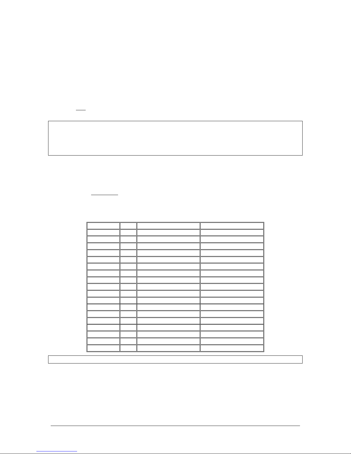
430 Volt, modulated 95% with 1300 Hz, signal will illuminate the amber (M) marker light, and that
marker audio is present in the headphones when the Marker Audio (MKR) push-button has been depressed. Select SPR for speaker to verify marker audio availability on the cabin speaker. Verify that the
white (I) and blue (O) lights will illuminate within 3dB of the amber lamp, with 3000 HZ and 400 Hz
applied, respectively.
2. Put unit in High Marker sensitivity (See §3.7 ). Repeat with the unit in HIGH sensitivity, 160 V with
applied.
3. Connect the marker antenna and verify proper operation.
2.11.4 Bluetooth Checkout
Verify that the PMA450A will “pair” with a Bluetooth device, and interface with cellular phone and Music
source. See section 3.12 for more information.
2.11.4.1 TEL Checkout
Pair the PMA450A with a Bluetooth telephone device. Verify that the pilot headset is connected to the cellular telephone system (if installed). Verify that by using the pilot side PTT, the pilot can transmit on the
other selected radio (Com 1 or Com 2). The telephone function will allow any person heard by the pilot on
the intercom, also heard on the telephone.
2.11.5 Internal Recorder Checkout
With headset plugged into pilot’s side jacks, tune COM 1 to local frequency, such as FSS or ATC ground.
Select Com 1 on mic selector switch, and record several incoming radio transmissions.
Press the Com receiver pushbutton (C1 or C2) that corresponds to the selected radio transmitter and hold
for approximately one second. This action will then automatically play back the last recorded message.
This audio should appear in the pilot and copilot headsets, and only be incoming transmissions from the
transceiver selected in the mic select switch. Depress the audio panel or yoke mounted playback switch,
and verify that messages play, in the order received. Repeat for other COM The playback will be stopped
by audio on the selected com. The message can be replayed from the beginning, and audio received during
the playback will not be stored.
2.12 Final Inspection
Verify that the wiring is bundled away from all controls and no part of the installation interferes with aircraft
control operation. Move all controls through their full range while examining the installation to see that no
mechanical interference exists. Verify that the cables are secured to the aircraft structure in accordance with
good practices, with adequate strain relief. Ensure that there are no kinks or sharp bends in the cables and
coaxial cables. Verify that the cables are not exposed to any sharp edges or rough surfaces, and that all contact
points are protected from abrasion.
Complete documentation that may be required, such as a logbook entry, weight and balance computation and
FAA Form 337. Sample text for FAA Form 337, and instructions for continuing airworthiness can be found
in Appendix F. Return completed warranty registration application to PS Engineering, or complete online at
www.ps-engineering.com.
Page 21
PS Engineering
PMA450A Audio Selector Panel and Intercom System
Installation and Operator’s Manual
200-450-0100 Page 3-1 Rev. 5, September 2017
Section III OPERATION
3.1 SCOPE
This section provides detailed operating instructions for the PS Engineering PMA450A, Audio Selector
Panel/Marker Beacon Receiver/Intercom Systems. Please read it carefully before using the equipment so that
you can take full advantage of its capabilities.
This section is divided into sections covering the basic operating areas of the PMA450A systems. They are
Communications Transceiver Selection, Audio Selector, Intercom, Marker Beacon Receiver and special
functions, including the Bluetooth® functionality in the PMA450A.
1
2
3
4 5
6
8
9
7
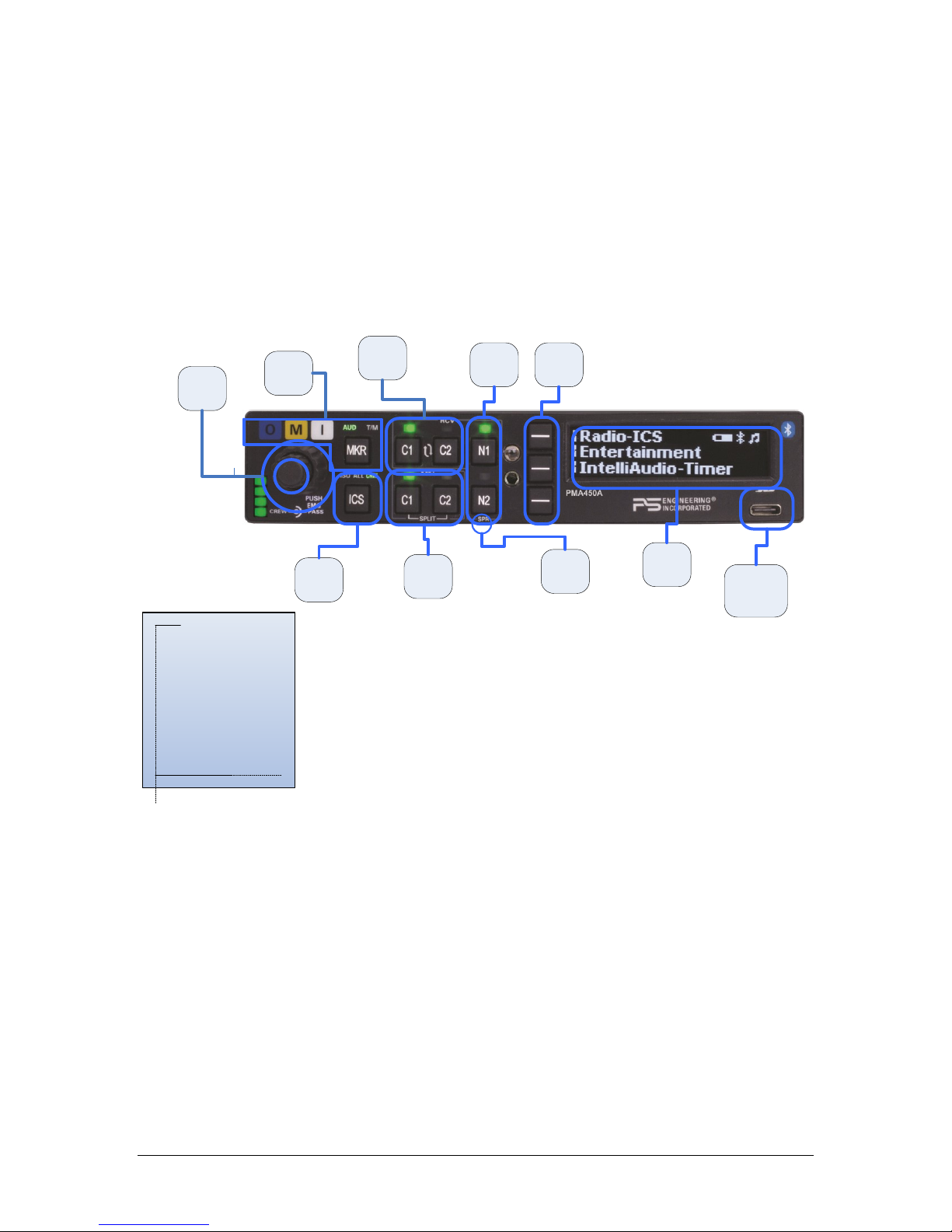
10
1. Volume on/off
2. Transmit Selection
3. Receiver Selection
4. Navaid Selection
5. Line Select buttons
6. OLED Display
7. Speaker Selection
8. Intercom Mode
9. Marker
10. USB Power Port
Figure 3-1 PMA450A Operating Controls
3.2 Power and Fail Safe (1)
Unit power is turned on and off by pushing the volume knob (1). There is a built in delay to prevent accidental
shut off while adjusting the intercom volume in turbulent conditions. In the OFF or "EMG" position, the pilot
headset is connected directly to Com 1 as well as unswitched input #1. This allows communication capability
regardless of unit condition. Any time power is removed or turned OFF, the audio selector will revert to failsafe mode. If fail-safe audio is present in both ears of a stereo headset, or completely absent, verify that a
stereo headset is used and is selected for stereo mode.
The power switch controls all audio selector panel functions, intercom and marker beacon receiver. All transceiver and receiver selections will be remembered and return to the last state when turned on.
3.3 Display Menu Selection (6)
The PMA450A uses an Organic Light Emitting Diode (OLED) Display and three line-select buttons to access
advanced functionality in a very logical manner. Press the line select key to select a specific item on each
Page 22
PS Engineering
PMA450A Audio Selector Panel and Intercom System
Installation and Operator’s Manual
200-450-0100 Page 3-2 Rev. 5, September 2017
menu. Items are toggled on and off by pressing the line select key as well. A long press (> 1 second) will also
back up one menu level.
When navigating the menus, the screen will automatically return to this “home” screen after a period of
inactivity. This delay time is configurable from the initialization menu as well, for between 1 and 20 seconds.
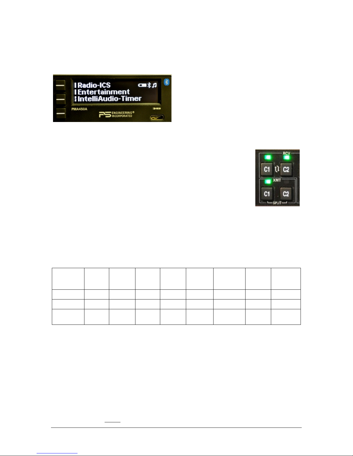
A vertical bar next to a button indicates the button can
perform a function on that menu.
A split bar indicates that a secondary function is
available when that button is held for more than one
second. These functions are:
Music on/off for the pilot (bottom button)
Figure 3-2 Top level Menu
3.4 Communications Transmit (XMT) Selection (2)
The PMA450A has four buttons to select communications transceiver functions, two
each C1 and C2. C1 refers to VHF COM 1, and C2, to VHF COM 2. To select a VHF
COM for transmit; push the lower button in the XMT (transmit) section. The radio is
automatically selected to receive incoming radio calls when the XMT is selected. With
a PMA450A, you will never transmit on a radio that you are not receiving.
To select a VHF COM radio to listen only, push the C1 or C2 button in the RCV
(Receive) section.
The PMA450A will remember when you have selected a radio for receive only, and
then switch to it for transmission and switch back.
3.4.1 Split Mode
In the SPLIT mode, the pilot position transmits and receives on COM 1, and the copilot can transmit and
receive on COM 2 independently.
Pressing the C1 and C2 XMT buttons (above the └ SPLIT ┘ legend), puts the PMA450A into SPLIT com
mode.
In split mode:
Position
COM 1
Re-
ceive
COM 1
Trans-
mit
COM 2
Re-
ceive
COM 2
Trans-
mit
Switched
Audio
Unsw. Au-
dio
Copilot
Inter-
com
Passen-
ger Inter-
com
Pilot
Yes
Yes
NO
NO
Yes
Yes
NO
NO
Copilot
NO
NO
Yes
Yes
NO
Yes
NO
NO
Passengers
NO
NO
NO
NO
NO
NO
NO
YES
The intercom is deactivated automatically when you enter SPLIT mode.
o Push the ICS button until the green LED lights up CRW to restore intercom between pilot
and copilot.
o Intercom between crew and passengers is not possible in split mode
The spatial component of IntelliAudio is defeated in split mode.
To exit SPLIT mode, reselect C1 or C2 XMT button
3.5 COM Audio Selector (3)
Communication audio from the other radio, not selected for transmit, can be heard by pressing the associated
RCV button. You will always hear the audio from the selected transceiver.
Page 23
PS Engineering
PMA450A Audio Selector Panel and Intercom System
Installation and Operator’s Manual
200-450-0100 Page 3-3 Rev. 5, September 2017
3.5.1 Swap Mode (Switch from Com 1 to Com 2 remotely)
With an optional yoke mounted, normally open momentary switch, the pilot can change from the current
Com transceiver to the other by pressing this switch. To cancel "Swap Mode," either press the yoke mounted
switch again, or select a different Com with the XMT buttons.
The panel- or yoke-mounted optional “swap” switch can also act as a remote intercom mode selector. A long
(>1 second) press of the swap switch will increment the intercom mode selector from ISO-ALL-CRW-ISO,
etc. each time the button is pressed and held.
3.5.2 IntelliAudio® Dimensional Audio
Various audio signals are presented to the DSP and processed to “appear” in a different location to the crew.
“Multi-Talker” (US Patent #7,391,877) specifies up to nine locations. This helps the crew to better compre-
hend speech by locating it in a manner more easily differentiated by the human brain.
Intercom and other audio is not spatially processed, only the pilot and copilot VHF COM audio.
You must use stereo headsets, in stereo mode for this feature.
The spatially processed dimensional sound in the PMA450A can be adjusted to accommodate the user pref-
erences.
This adjustment allows the Spatial Audio inputs to be “relocated” on any of nine (9) defined “Head Related
Transfer Function” (HTRF) locations.
Push IntelliAudio → IntelliAudio Config to access. In the IntelliAudio® mode, repeated pressing of the
COM 1 or COM 2 line select buttons moves the corresponding half-circle cursor to the locations relative to
the listener graphic in sequence.
Pressing the Done button exits the configuration setting mode. This setting is recalled at system power up.
Figure 3-3 IntelliAudio – True Dimensional Sound, Spatial Location Display, showing C1 at 30°left
and C2 at 90° right of center.
3.5.2.1 IntelliAudio: Auto mode
When IntelliAudio is in Auto mode, the separation will switch
to mono mode after one of the radios has been quiet for more
than 60 seconds. Separation will automatically return when
both radios are active.
3.5.3 Com Monitor Mode
The PMA450A is equipped with a Monitor function, which allows a secondary com radio audio to be muted
by the primary radio (selected for transmit).
To toggle the Monitor mode on and off, Press IntelliAudio → MONITOR
NOTE: Monitor Mode and Spatial Audio Processing (IntelliAudio) are mutually exclusive – entering one
mode will cancel the other.
Page 24
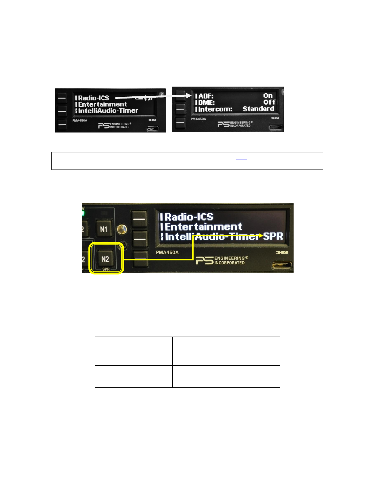
PS Engineering
PMA450A Audio Selector Panel and Intercom System
Installation and Operator’s Manual
200-450-0100 Page 3-4 Rev. 5, September 2017
3.5.4 Navaid Selection (4)
VHF Navigation receivers can be selected directly from the front panel with the N1 and N2 (VHF Navigation
receiver 1 and 2) buttons. The selected source is indicated by a green LED.
Additional navigation aid or other audio sources can be selected using the OLED menus.
Press the bottom line select RADIO →and desired audio source.
NOTE: Switched Inputs can be renamed at the configuration set up. See §3.13 for more information.
In SPLIT mode, only the pilot will hear selected navigation audio.
3.6 Speaker Amplifier (7)
To activate the PMA450A cockpit speaker output, press and hold the bottom line-select button (SPR) for one
second or until SPR appears in the display.
In “Split Mode” all audio that the pilot hears will also be present in the speaker.
Unswitched audio #1 & #2, (the inputs dedicated to autopilot disconnect, altimeter warning, etc.) will come
through the speaker regardless of the speaker button position.
When a cell phone call is active, the selected radio audio is removed from the speaker.
Depending on installation, important audio annunciations such as radar altimeter or autopilot disconnect will
come over the speaker even if it is not selected, while other unswitched, but muted inputs, such as GPS alerts,
will only be present if the SPR button is selected. Consult your professional avionics installer for these important configuration details.
Unswitched
Input
Hear in
Fail Safe
(Pilot)
Hear in
Crew Headset
Hear in SPR
1
Yes
Yes
Yes
2
No
Yes
Yes
3
No
Yes
When SPR selected
4
No
Yes
When SPR selected
3.6.1 Public Address Function
To access PA function, press and hold the N1 button for more than 1 second, until the display changes to PA
SPR.
Page 25
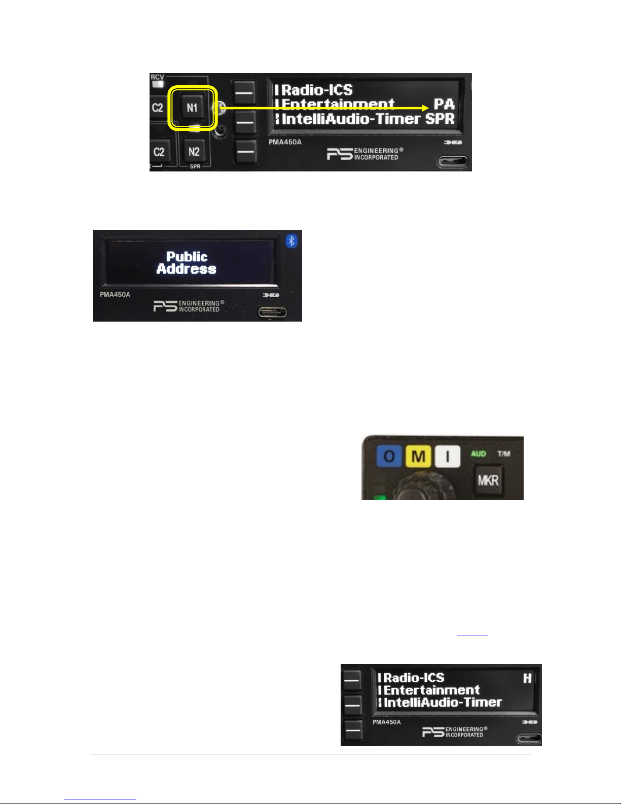
PS Engineering
PMA450A Audio Selector Panel and Intercom System
Installation and Operator’s Manual
200-450-0100 Page 3-5 Rev. 5, September 2017
When PA mode is active, all microphones except for the Pilot will be disabled for complete and uninterrupted
announcements.
The pilot microphone will be heard on the speaker and headsets when the pilot PTT is used.
The copilot can continue to use the selected com radio while the pilot will be heard over the speaker.
To exit PA mode, push and hold the N1 button again until PA is off or cycle power on the audio panel.
3.7 Marker Beacon Operation (9) (unit part numbers 050-450-0101, -0102
only)
The Marker Beacon Receiver uses visual and audio indicators to alert you when the aircraft passes over a 75
MHz transmitter.
The audio from the Marker Beacon Receiver can be heard by pushing the "MKR" button. AUD will light up
green.
The Blue lamp, labeled “O”, is the Outer Marker lamp and has
an associated 400-Hertz 'dash' tone. The lamp and tone will be
keyed at a rate of two tones/flashes per second when the aircraft
is in the range of the Outer Marker Beacon.
The Amber lamp, labeled “M”, is the Middle Marker lamp and
is coupled with a 1300 Hertz tone. It is keyed alternately with short 'dot' and long 'dash' bursts at 95 combinations per minute.
The White lamp, labeled “I”, is the Inner marker and has a 3000 Hertz 'dot' tone. The lamp and tone will be
keyed at a rate of six times per second.
Holding the MKR button for one second activates marker test lamp, labeled "T/M" and illuminates all three
lamps simultaneously to assure the lamps (internal and external) are in working order. TST does not activate
MM autopilot sense output. Releasing the button returns to the last sensitivity.
Pressing the marker mode select (“T/M”) for one second, while beacon audio is active, will also cause the
marker audio to mute for that beacon. The next beacon received will re-activate the audio.
The marker beacon receiver audio volume can be adjusted from the user setup menu (see §3.16.5).
3.7.1 Marker Beacon Sensitivity
Press and hold the MKR button for about two seconds, until
the letter H appears in the OLED display, indicating that
the Marker beacon sensitivity is in the High Sense Mode.
Repeat to switch back to Low Marker Sense (“H” disappears.)
[Serial Number D1150 and below only: Marker Beacon
sensitivity is set using an external toggle switch, if desired.
Page 26

PS Engineering
PMA450A Audio Selector Panel and Intercom System
Installation and Operator’s Manual
200-450-0100 Page 3-6 Rev. 5, September 2017
The PMA450A defaults to low sensitivity, and will be in high sensitivity if the switch is closed, connecting
J2-Pin 30, to ground. ]
3.8 Intercom Operation (8)
3.8.1 IntelliVox® Intercom VOX-Squelch
No adjustment of the IntelliVox® squelch control is necessary. Through three individual signal processors,
the ambient noise appearing in all six microphones is constantly being sampled. Non-voice signals are
blocked. When someone speaks, only their microphone circuit opens, placing their voice on the intercom.
The system is designed to block continuous tones; therefore people humming or whistling in monotone may
be blocked after a few moments.
For consistent performance, any headset microphone must be placed within ¼-inch of your lips, preferably
against them. (ref: RTCA/DO-214, 1.3.1.1 (a)).
NOTE
It is also a good idea to keep the microphone out of a direct wind path. Moving your head through a vent air
stream may cause the IntelliVox® to open momentarily. This is normal.
The IntelliVox® is designed to work with normal aircraft cabin noise levels (70 dB and above). It loves airplane noise! Therefore, it may not recognize speech and clip syllables in a quiet cabin, such as in the
hangar, or without the engine running. This is normal.
For optimum microphone performance, PS Engineering recommends installation of a Microphone Muff Kit
from Oregon Aero (1-800-888-6910). This will not only optimize VOX performance, but will improve the
overall clarity of all your communications.
Manufacturer
Model
Mic Muff™ Part Number
Bose
Dynamic
Electret
M87 Dynamic
90010
90015
90020
David Clark
H10-30
H10-20, H10-40
H10-13.4
90010
90015
90015
Lightspeed
All
90015
Peltor
7003
7004
90010
90015
Pilot
11-20 & 11-90
90015
Sennheiser 90015
Telex
Airman 750, Echelon
AIR3000
90015
90010
Table 3-1 Mic Muff ™ Part Numbers
3.8.2 Intercom Volume Control (1)
The smaller inner volume control knob adjusts the loudness of the intercom for the pilot and copilot. It has
no effect on selected radio levels, music input levels or passengers' volume level. The green volume bar
indicator shows the level of the crew volume by default.
The outer, larger volume control knob controls intercom volume for the passengers. It has no effect on radio
or music levels. When the outer knob is moved, the green volume bar indicator will switch to show the level
of the passenger’s intercom volume, reverting to the crew after a few seconds.
Adjust the radios (at the radio itself) and intercom volume for a comfortable listening level. Most general
aviation headsets today have built-in volume controls; therefore, volume also can be further adjusted at the
individual headset.
Page 27

PS Engineering
PMA450A Audio Selector Panel and Intercom System
Installation and Operator’s Manual
200-450-0100 Page 3-7 Rev. 5, September 2017
3.8.2.1 Monaural headsets
The pilot and copilot positions work with stereo or mono headsets. However, IntelliAudio will not be presented correctly unless stereo headsets are used, and oriented correctly on the head, left and right.
NOTE: For the full effect of IntelliAudio® Dimensional Sound, stereo headsets must be used, and the
left/right orientation observed.
All passenger headsets are connected in parallel. Therefore, if a monaural headset is plugged in to a
PMA450A Stereo installation, one channel will be shorted. Although no damage to the unit will occur, all
passengers with stereo headsets will not hear one channel, unless they switch to the “MONO” mode on their
headset.
NOTE: Mono headsets that short the tip and ring (i.e. older models) will introduce some audio distortion when used. Modern, stereo headsets are recommended in all positions.
3.8.3 Intercom Modes (8)
The “ICS” pushbutton switch on the panel provides the selection of the three intercom modes
This button cycles through the intercom modes, from left to right, then right to left as: ISO, ALL CRW and
CRW, ALL, ISO. A green indicator shows which mode is currently active.
The description of the intercom mode function is valid only when the unit is not in the "Split" mode. Then,
the pilot and copilot intercom is controlled by the ICS button selecting CRW.
ISO: The pilot is isolated from the intercom and is connected only to the aircraft radio system. He will hear
the aircraft radio reception (and sidetone during radio transmissions). Copilot will hear passengers’ intercom
and Music, while passengers will hear copilot intercom and Music. Neither will hear aircraft radio receptions
or pilot transmissions. The pilot can hear music if desired. See §3.9.3
ALL: All parties will hear the aircraft radio and intercom. Crew and passengers will hear selected Music.
During any radio or intercom communications, the music volume automatically decreases. The music volume
increases gradually back to the original level after communications have been completed.
CREW: Pilot and copilot are connected on one intercom channel and have exclusive access to the aircraft
radios. They may also listen to Music 1. Passengers can continue to communicate with themselves without
interrupting the Crew and may listen to Music as configured.
3.8.3.1 Remote ICS Mode Control
The panel- or yoke-mounted optional “swap” switch can also act as a remote intercom mode selector in units
with serial and above. A long (>1 second) press of the swap switch will increment the intercom mode selector
from ISO-ALL-CRW-ISO, etc. each time the button is pressed and held. A short press activates the COM 1
to COM 2 to COM 1 swap function.
3.8.3.2 Alternate Intercom Mode
The PMA450A includes an Alternate Intercom Mode. This mode allows intercom communications between
crew and passengers, without interrupting the crews radio communications. The passengers do not hear the
aircraft radio audio. The passenger microphones are muted, such that the crew cannot hear the passengers’
microphone audio while the radio is active. Passengers can still talk to each other.
To enable the Alternate Intercom Mode, press RADIO-ICS: to switch between Standard, Alternate and Co-
pilot as Passenger modes. This state is remembered during power cycles.
Page 28

PS Engineering
PMA450A Audio Selector Panel and Intercom System
Installation and Operator’s Manual
200-450-0100 Page 3-8 Rev. 5, September 2017
Alternate Intercom Mode enabled
3.8.3.3 Copilot as Passenger (CP PAX) Intercom Modes
This function is useful when the right seat occupant does not wish to interact with the aircraft operation.
Copilot as Passenger Enabled
3.8.3.4 Copilot as Passenger (CPAX) Serial Number E45A1373 and up.
In this mode, the copilot position is treated as a passenger. The position will have intercom with the pilot
position, except when there is radio traffic, will not hear any selected radio audio and cannot transmit on the
radio. The intercom microphone to the pilot position will not be heard while there is radio audio present.
The volume knob for the Copilot/Pax position changes in this mode. With CP Pax mode enabled, the copilot
seat is controlled via the passenger knob. Also, pressing the ICS button toggles between ISO and All only.
To activate Copilot as passenger, Radio-ICS Intercom: CPX.
3.9 Music Control, Distribution and Muting
The bottom menu, bottom line select button toggles the music on or off for the pilot. When pilot music is
active, a music icon (♫) appears in the display.
The PMA450A has two independent music inputs at the rear connector, and a front panel jack. The
PMA450A also has the ability to receive streaming music from a Bluetooth-enabled device.
The Bluetooth, Music 1 and Music 2 inputs can be selectively delivered to the pilot, copilot and/or passengers
using the music distribution menu.
The Bluetooth option is only available when connected to a Bluetooth compatible source.
Figure 3-4 Top Music Menu
Press Music → Music Distribution→ and select desired combination.
Page 29

PS Engineering
PMA450A Audio Selector Panel and Intercom System
Installation and Operator’s Manual
200-450-0100 Page 3-9 Rev. 5, September 2017
Figure 3-5 Music distribution menu
In Copilot as Passenger Mode, Passengers are designated Front (was copilot) and “rear” (was passenger).
Figure 3-6 Music distribution menu, Copilot as Passenger
NOTE:
All music devices should be turned off for takeoff, landing, or any critical phase of flight. FAA Regulation
14 CFR 91.21 restricts the use of portable electronic devices.
§91.21 “(a) Except as provided in paragraph (b) of this section, no person may operate, nor may any operator
or pilot in command of an aircraft allow the operation of, any portable electronic device on any of the following U.S.-registered civil aircraft. . .
“(b)(5) Any other portable electronic device that the operator of the aircraft has determined will not cause
interference with the navigation or communication system of the aircraft on which it is to be used.”
You can refer to Advisory Circular 91.21-1A for more information, at http://www.faa.gov
3.9.1 Music Muting
The SoftMute™ circuit will mute the music whenever there is conversation on the radio, the intercom, or
both, depending on the “Mute” mode selected. When that conversation stops, the music returns to the previ-
ous level comfortably, over a second or so.
The mute mode functions are controlled through Music Mute Menu which has three modes for each music
input. Mute ALL, Mute Off “Karaoke” & Radio Mute.
The PMA450A always defaults to Mute ALL when turned on, unless “Mute Recall” is selected in setup menu.
In ALL- music will mute with either intercom or radio
Mute OFF, or “Karaoke” mode - music will not mute except during radio transmissions.
Radio - Radio will mute music, but intercom will not mute music.
In addition to the panel mute menu, a remote switch may be installed to allow the passengers local access
to their Karaoke mode. When this switch is grounded, the menu choice is overridden.
3.9.2 Music Volume
The volume of the music inputs can also be adjusted from the menu of the PMA450A:
Press Music → Music Volume → Desired music input. The LED Volume bar and the numeric volume will
show the volume level.
Page 30

PS Engineering
PMA450A Audio Selector Panel and Intercom System
Installation and Operator’s Manual
200-450-0100 Page 3-10 Rev. 5, September 2017
Figure 3-7 – Music Volume screen
3.9.3 Music in Pilot ISO mode
When the isolate (ISO) mode is activated, the music for the pilot is automatically disabled. If desired, the
pilot can elect to hear music in the ISO mode with a long press or holding the home menu button or the ICS
button, while in the ISO mode.
The pilot can select any music source from the Music distribution menu.
3.10 Bluetooth® connection
The PMA450A has a Bluetooth interface. The audio panel is always “discoverable,” so you just need to
search for the PMA450A from your Bluetooth-equipped phone or music source. The default access code is
0000, if needed. Once the PMA450A has been “paired” with your Bluetooth device, the TEL distribution
will act as described in § 3.11.1.
When Bluetooth is active, a Bluetooth icon and the battery status of the device is displayed in the upper right
corner of the home display.
3.10.1 Pairing and un-pairing Bluetooth devices
The PMA450A can be paired with up to eight individual devices. When that number is exceeded, the
PMA450A will drop a device to allow the new device to be added.
If the audio panel is turned on before the Bluetooth device, you will have to manually connect from your
Bluetooth device. Otherwise, the audio panel should connect automatically.
When the PMA450A is first powered on, an auto connect sequence attempts to connect the BT to previously
paired devices. During this period connection times may vary from 10 seconds to 1 minute. Although the
PMA450A can store up to eight devices, we recommend limiting the number if practical. During start-up, the
PMA450A will look for each previously paired device which may slow connection time.
Hint, if your old phone is not recognized by the PMA450A, you may need to reset from the Bluetooth menu.
Page 31

PS Engineering
PMA450A Audio Selector Panel and Intercom System
Installation and Operator’s Manual
200-450-0100 Page 3-11 Rev. 5, September 2017
3.10.1.1 Paring separate music and telephone devices
It is possible to use a different music source (iPad, iPod with Bluetooth adapter, Bluetooth enabled laptop,
etc) and telephone. However, only one music source can be streaming at a time.
NOTE: A previously paired iOS Hands Free device may experience from one to several connect/disconnects
sequences when the PMA450A is first powered on. This is normal and will result in the device remaining
connected when the auto connect process is completed.
If two iOS devices are paired and connected to the PMA450A, and one of them does not autoconnect on the
next power cycle (perhaps it isn’t in the sirplane, or the Bluetooth is turned off), it will be ignored until it is
reconnected manually.
3.11 Bluetooth® Telephone Mode
The PMA450A serves as a full duplex interface for telephone systems such as portable cellular phones with
Bluetooth connectivity.
Warning:
United States FCC Regulations contained in 47 CFR § 22.925 currently contain prohibition on airborne operation of cellular telephones. “Cellular telephones installed in or carried aboard airplanes, balloons or any
other type of aircraft must not be operated while such aircraft are airborne (not touching the ground). When
any aircraft leaves the ground, all cellular telephones on board that aircraft must be turned off.”
In ALL intercom mode, all crew and passengers will be heard on the phone when they speak. All will hear
selected audio. Com audio is automatically heard in the headsets (unless in Alternate Intercom Mode).
In CREW mode, the pilot and copilot are connected to the telephone. The pilot and copilot will have transmit capability on the selected transceiver, Com 1 or 2, simply by using their respective PTT switch.
In ISO intercom mode, when the PMA450A is in the TEL mode, the pilot position is in the "Phone
Booth." Only the pilot will hear the telephone, and only he will be heard. He will also have access to Com 1
or 2, and will transmit on that radio using the PTT. All selected audio is provided.
NOTE
PS Engineering does not guarantee compatibility with personal cellular telephones.
3.11.1 Bluetooth Reset
If Bluetooth devices have trouble connecting, it may be necessary to reset the Bluetooth Module. The
PMA450A Bluetooth Reset function is accessible from the setup menu.
During the unit boot up process (while the version numbers appear on the screen), press the lower line select
button.
This places the unit into the “User Setup Mode- home screen”, and allows resetting the Bluetooth Module
Page 32

PS Engineering
PMA450A Audio Selector Panel and Intercom System
Installation and Operator’s Manual
200-450-0100 Page 3-12 Rev. 5, September 2017
When Unpair All is pushed, the Bluetooth Module is reset and ALL Bluetooth devices are erased from the
audio panel, and can then be added back as desired. This is useful in some cases where the unit or operator
lose track of the devices paired, and cannot get them to connect.
Cycle the PMA450A power to exit setup screen.
3.11.2 Bluetooth PIN
The PMA450A can be configured to require a Personal Identification Number (PIN) to pair, or this function
can be disabled.
As delivered from the factory, the PIN is disabled. To enable the PIN, and set the PIN to be used,
Enter the user setup mode
More
Bluetooth
PIN (Note when PIN is changed from Disabled to a value, the Bluetooth will reset, and clear all paired
devices)
To remove the PIN, press PIN again, while the cursor is on a number.
3.11.3 Bluetooth Cellular telephone sidetone
Some cell phones provide sidetone, and when combined with unit sidetone can cause audio distortion. In the
PMA450A telephone sidetone can be enabled or disabled on the Telephone menu when a call is active.
3.12 Wired Satcom/Cell Phone input
The PMA450A can accommodate a wired telephone input as well as a Bluetooth connection. However, only
one can be active at a time. The Bluetooth symbol is absent from wired menu.
The wired telephone screen menu is activated when audio is detected from the phone. Sidetone and telephone
volume can be controlled from this menu. The telephone audio distribution is the same as Bluetooth, above.
This menu will switch off 25 seconds after the incoming conversation ends, or press End Call.
NOTE: The PMA450A does NOT answer or hang up the wired phone from this menu.
Page 33
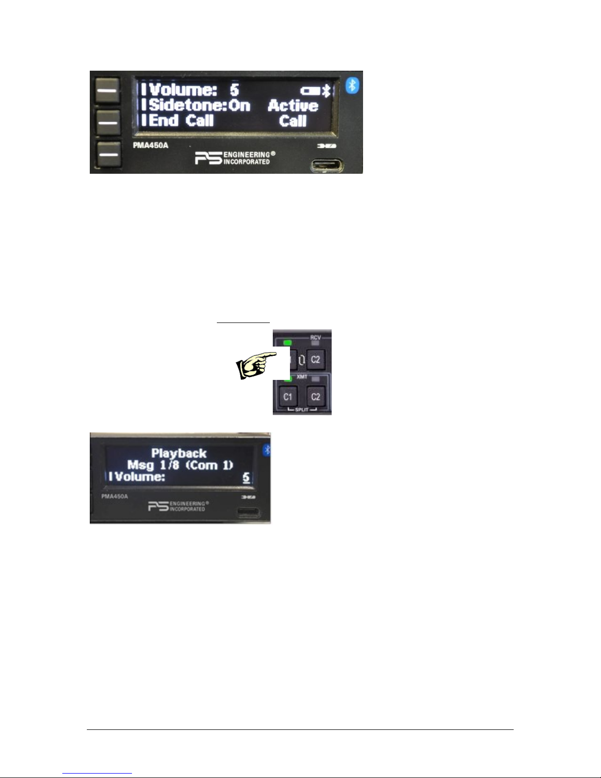
PS Engineering
PMA450A Audio Selector Panel and Intercom System
Installation and Operator’s Manual
200-450-0100 Page 3-13 Rev. 5, September 2017
3.13 Internal Recorder and playback
The PMA450A comes equipped with an internal recorder. This digital system stores the last incoming audio
from the radio you have selected for transmit. It can store as many of 8 incoming messages, and up to 45
seconds of audio. The pilot and copilot hear the playback.
Recording is automatic. To play back the last recorded message, press and hold the COM Receive pushbutton associated with the selected radio transmitter for about one (1) second. You can either wait for the message to finish playing before accessing the prior message, or cancel the current playback and step backward. To cancel the playback, press and hold the COM receive playback button for two seconds (2). The
next time the button is pressed for one (1) second, the next earlier message will be heard. The playback will
stop whenever there is more incoming selected com audio, and the message can be replayed from the beginning by pressing the selected Com Receive button again for 1 second.
Figure 3-8 Playback Controls
Figure 3-9 Playback Display
3.14 PS Streamer Operation
The PMA450A can be equipped with a PS Streamer audio module, part number 010-894-0000.
This module provides a Bluetooth® output of selected signals from the audio panel. These can be
streamed to compatible devices such as a GoPro camera equipped with a SEMA adapter.
Page 34
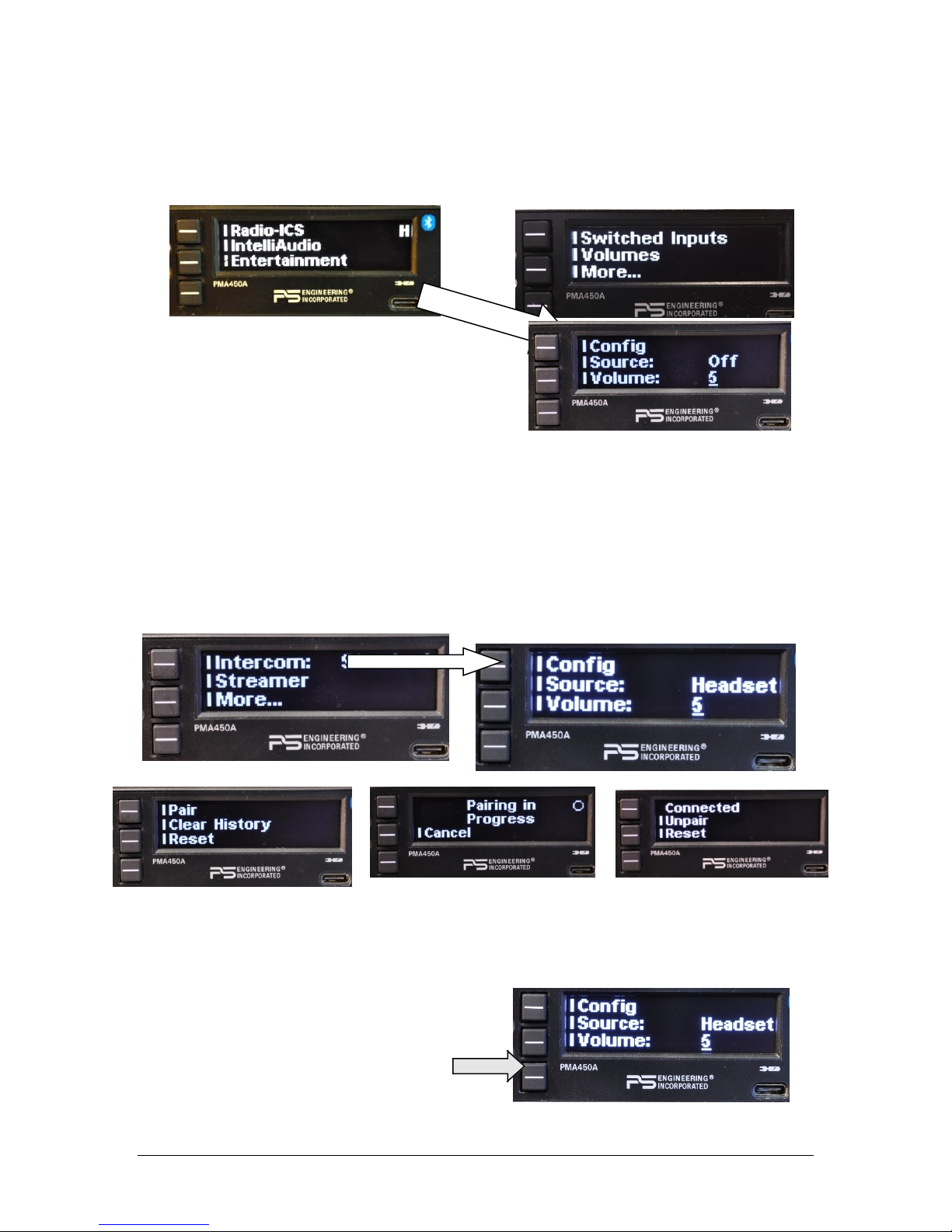
PS Engineering
PMA450A Audio Selector Panel and Intercom System
Installation and Operator’s Manual
200-450-0100 Page 3-14 Rev. 5, September 2017
3.14.1 Pairing
To pair the PMA450A PS Streamer with a compatible device, access the streamer menu from Radio-ICS More Streamer Config Init Pair. This will initiate the paring sequence, and you
may have to initiate the pairing on the other device as well.
This may take 30 seconds to complete.
After the module is paired the first time, it will connect
to that device each time it is activated.
Depending on the Bluetooth device receiving the audio,
pairing may have to be initiated on the device, or the audio panel first.
NOTE: During the time that the Streamer module is in the pairing process, the main Bluetooth
connection to the telephone/music is inhibited, so music and telephone will not be available. When
paired, a Bluetooth symbol will appear in the display.
3.14.2 Streamer on/off
Select: Radio-ICS More Streamer Source
Press the middle line select button to activate the PS Streamer source when it has been turned off.
The PS Streamer defaults to “off” when the audio panel is turned
on each time. You will need to activate the PS Streamer for each flight when desired, but pairing
will not be necessary. The module will reconnect when activated.
3.14.3 Source Selection
The output can contain either the audio heard by the
pilot (radio, intercom, music, etc.) or only communications radio audio.
From the PS Streamer menu, push the middle
line select button to toggle between communication radio audio and all audio heard in the pilot
headset, including radio, intercom, music and telephone.
Page 35

PS Engineering
PMA450A Audio Selector Panel and Intercom System
Installation and Operator’s Manual
200-450-0100 Page 3-15 Rev. 5, September 2017
Streamer Volume
The volume of the radio output to the PS
Streamer module can also be adjusted, press Ra-
dio-ICS more . . . Streamer Volume, and use
the small knob to set the level. We recommend starting
at 10, the highest level.
Page 36
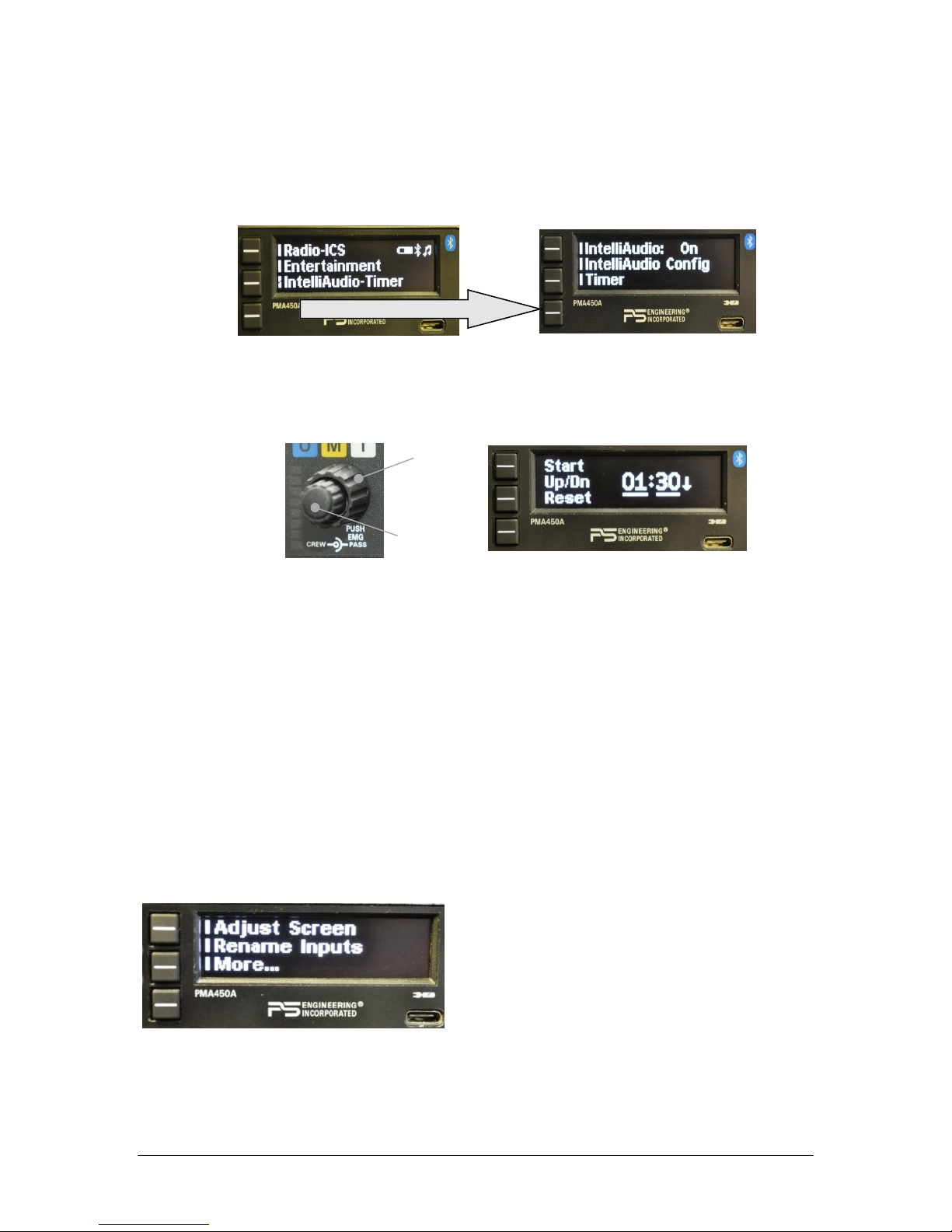
PS Engineering
PMA450A Audio Selector Panel and Intercom System
Installation and Operator’s Manual
200-450-0100 Page 3-1 Rev. 5, September 2017
3.15 Timer Functions (Serial Number E45A1373 and up only)
The PMA450A contains a timer function with count down, or count up functions. This can be used as a
convenient reminder for timed instrument approaches, fuel tank switching, flight elapsed time, etc. The
Timer is accessed from the main menu, bottom button.
3.15.1 Setting the timer
Press the SET button and use adjust the desired time using the outer knob for minutes, and the inner knob for
seconds, up to 99:99.
3.15.2 Count Down
Press Start to begin counting down.
The display reverts to normal after a few seconds. Then as the countdown progresses, the display will mo-
mentarily show remaining time as the interval is divided in half (from 1 minute, then 30 seconds, then 15
seconds, etc). At one minute remaining, an audio alert says “One Minute.” The display show remaining time
at 10 seconds, and audio alert says “Time Expired.”
The set time is remembered until changes, and can be reset to the last value.
3.15.3 Count up
The count up timer simply shows elapsed time since START, and counts to 99 minutes, 99 seconds.
3.16 User Setup menus
The PMA450A has several user adjustable functions accessible from a setup menu.
Figure 3-10 User Configuration Menu
During the unit boot up process, press the lower line select button until the setup screen appears.
Cycle the PMA450A power to exit setup screen.
MINUTES
SECONDS
Page 37
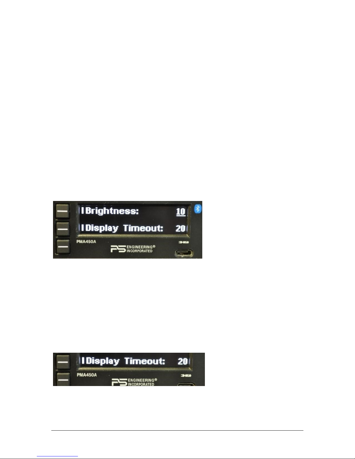
PS Engineering
PMA450A Audio Selector Panel and Intercom System
Installation and Operator’s Manual
200-450-0100 Page 3-2 Rev. 5, September 2017
During the unit boot up process, press the lower line select button when the version screen appears. This
shall place the unit into the “User Configurable Mode- home screen”. This allows adjustment for:
Adjust Screen (OLED)
Rename Switched Inputs
Recall Mute Mode
Bluetooth
Cycle the PMA450A power to exit setup screen.
3.16.1 Adjust Screen (OLED Adjustment)
The first item is adjustments to the display, allowing the installer or user to tailor the intensity to suit the
cockpit conditions.
OLED will vary in real time while adjustments are made. LED bar & numeric indication will vary.
3.16.1.1 Brightness
Adjusting the Brightness level requires selecting the smaller button and then turning the inner knob. Counter
clockwise to lower the number (level of Brightness) and clockwise to increase the number (level of Brightness). The display brightness also automatically tracks the ambient light.
To change the display:
Press the line select for the desired item
Turn the small, inner knob to change the brightness as desired.
Cycle the PMA450A power to exit setup screen.
Figure 3-11 OLED Menu
3.16.1.2 Display Timeout
This is a feature that allows the end user to adjust how quickly the screen menus timeout (revert to main
menu).
NOTE: A long press (>1 second) will back up the menu one level.
This allows adjustment of the timeout screen and can be configured from 1 second to 30 seconds by turning
the inner knob.
For a user who is unfamiliar with the product, this will give them enough time to learn the system. After
becoming more familiar, the user can speed up the menu screen timeout as desired.
Cycle the PMA450A power to exit setup screen.
Figure 3-12 Display Timeout Menu
Page 38

PS Engineering
PMA450A Audio Selector Panel and Intercom System
Installation and Operator’s Manual
200-450-0100 Page 3-3 Rev. 5, September 2017
3.16.2 Remembering Music Mute Mode
As shipped by the factory, the PMA450A automatically default to “Mute Off.” This ensures that the music
will always be muted until positively changed by the pilot.
Owners who want the PMA450A to remember the last music mute state can set the “Recall Mute” in the user
setup menu.
The Copilot as Passenger mode reset on power up unless Recall ICS is selected by the owner.
3.16.3 Rename “Switched” Inputs
The system is factory set to default as ADF, DME & AUX as shown.
The three inputs are from top to bottom:
Switched input #1 J1, Pin 7 wrt Pin 8 (Default ADF)
Switched input #2 J1, Pin 21 wrt Pin 22 (Default DME)
The customer will have access to rename. Maximum 9 letters per line and A thru Z, a through z and 0 thru 9
will be available. Note: If no marker version PMA450A (-0201) an external marker can be connected to these
inputs.
Press the line select for desired input.
Turn the large outer knob to select the letter to change.
Turn the small, inner knob to increment or decrement the letter.
You can select 9 characters, A through Z, 1 through 9.
You can quickly clear the whole line by turning the outer knob to move the cursor all the way to
the right or left until the line clears.
Blank spaces can’t be added to the end of a string, but you can add a temporary character and go
back and change it to a space:
ADFA1
Change extra “A” to space ADF 1
Cycle the PMA450A power to exit setup screen.
Figure 3-13 Rename Input Menu
3.16.4 Bluetooth Setup
There are three Bluetooth functions that can be changed in the user setup screen, Unpair All, Paring PIN, and
device ID.
Page 39

PS Engineering
PMA450A Audio Selector Panel and Intercom System
Installation and Operator’s Manual
200-450-0100 Page 3-4 Rev. 5, September 2017
3.16.4.1 Unpair All (Bluetooth Reset)
When Unpair All is pushed, the Bluetooth Module is reset and ALL Bluetooth devices are erased from the
audio panel, and can then be added back as desired. This is useful in some cases where the unit or operator
loses track of the devices paired, and cannot get them to connect.
3.16.4.2 PIN:
The 4-digit PIN code can be changed to any number desired. This is useful if the owner wants to restrict
access to the audio panel Bluetooth functions.
Some phones will not pair if a Personal Identification Number (PIN) is required. To disable the PIN:
Enter configuration menu, select Bluetooth.
Select PIN code for editing. Press PIN button one more time.
“Bluetooth Reset” will appear on screen. When the menu returns, the PIN code will report “Disa-
bled”.
To re-enable the PIN code for a different device, press the PIN button. “Bluetooth Reset” will appear
on screen. When the menu returns, the last stored PIN code will be shown.
ID: The PMA450A can be renamed using this mode to show up on devices with a personalized identifier.
3.16.5 Volume Setup
Press RADIO → VOLUMES → MARKER, and turn the small knob to adjust the marker beacon volume.
The green volume bar and numerical readout will indicate the receiver volume in this menu. NOTE: marker
Volume cannot be turned completely off.
NOTE: PMA450A, P/N 050-450-0200, without Marker Beacon, will not have a Volume selection.
3.17 USB Charging Port (10)
The PMA450A contains a USB-C charging port that is capable of providing 5 VDC, 3.0 amps of current (at
least 15 watts) to power or charge the batteries in smart phones and tablets used as Personal Electronic Devices. This is NOT a data transfer jack.
Page 40

PS Engineering
PMA450A Audio Selector Panel and Intercom System
Installation and Operator’s Manual
200-450-0100 Page 4-1 Rev. 5, September 2017
Section IV – Warranty and Service
4.1 Warranty
In order for the factory warranty to be valid, the installations in a certified aircraft must be accomplished by
an FAA-(or other ICAO agency) certified avionics shop and authorized PS Engineering dealer. If the unit is
being installed by a non-certified individual in an experimental aircraft, a factory-made intercom harness
must be used for the warranty to be valid.
PS Engineering, Inc. warrants this product to be free from defect in material and workmanship for a period
of two (2) years from the date of sale. During the first twelve (12) months of the two-year warranty period,
PS Engineering, Inc., at its option, will send a replacement unit at our expense if the unit should be determined
to be defective after consultation with a factory technician. For the remaining twelve (12) months of the two-
year warranty period, PS Engineering, Inc., at its option, will send a similar replacement unit at the customers’
expense if the unit should be determined to be defective after consultation with an authorized PS Engineering
dealer.
All transportation charges for returning the defective units are the responsibility of the purchaser. All domestic transportation charges for returning the exchange or repaired unit to the purchaser will be borne by PS
Engineering, Inc. The risk of loss or damage to the product is borne by the party making the shipment, unless
the purchaser requests a specific method of shipment. In this case, the purchaser assumes the risk of loss.
This warranty is not transferable. Any implied warranties expire at the expiration date of this warranty. PS
Engineering SHALL NOT BE LIABLE FOR INCIDENTAL OR CONSEQUENTIAL DAMAGES. This
warranty does not cover a defect that has resulted from improper handling, storage or preservation, or unreasonable use or maintenance as determined by us. This warranty is void if there is any attempt to disassemble
this product without factory authorization. This warranty gives you specific legal rights, and you may also
have other rights, which may vary from state to state. Some states do not allow the exclusion of limitation of
incidental or consequential damages, so the above limitation or exclusions may not apply to you.
All items repaired or replaced under this warranty are warranted for the remainder of the original warranty
period. PS Engineering, Inc. reserves the rights to make modifications or improvements to the product without obligation to perform like modifications or improvements to previously manufactured products.
4.2 Factory Service
The units are covered by a two-year limited warranty. See warranty information. Call PS Engineering, Inc.
at (865) 988-9800 before you return any unit. This will allow the service technician to provide any other
suggestions for identifying the problem and recommend possible solutions.
After discussing the problem with the technician and you obtain a Return Authorization Number, ship product
to:
PS Engineering, Inc.
Attn: Service Department
9800 Martel Rd
Lenoir City, TN 37772
(865) 988-9800 FAX (865) 988-6619
Email: support@ps-engineering.com
Units that arrive without an RMA number, or telephone number for a responsible contact, will be
returned un-repaired. PS Engineering is not responsible for items sent via US Mail.
Page 41

PS Engineering
PMA450A Audio Selector Panel and Intercom System
Installation and Operator’s Manual
200-450-0100 Appendix A Rev. 5, September 2017
Appendix A – PMA450A Installation Drawings
J2 J1
Viewed from Back
15
30
44
1
16
31
15
30
44
1
16
31
Ground Lug
Ground Lug
475-440-0001 (x2)
Back plate assy
475-009-0001
ground lug (x2)
475-440-0001 (x2)
Screw w/was her
Ground lug detail
Rear plate detail (not to scale)
0.37 in
3.87 in
5.53 in
6.04 in
0.36 in
0.96 in
1.28 in
6.31in
1.28in
Ca u tio n : App ly s te ad y pr es sure t o the beze l wh il e sc re wi ng the un it i nt o th e tr ay t o
ens ur e even se at in g of t he u nit and co nnec tors.
Page 42

PS Engineering
PMA450A Audio Selector Panel and Intercom System
Installation and Operator’s Manual
200-450-0100 Appendix B Rev. 5, September 2017
Appendix B – J1 Connector Interconnect
Com 1 A udio Hi
Com 1 Mic Key
Com 1 Lo
Comm unicat ions
Transc eiv er #1
Comm unicat ions
Transc eiv er #2
Nav 1 Audio Hi
Nav 1 Audio Lo
VHF Nav 1
Nav 2 A udio Hi
Nav 2 A udio Lo
VHF Nav 2
SW2 Audio Hi
SW2 Audio Lo
Unswitched I nput #1 Hi
Unswitched Audi o Lo
Unswitche d Audio #1
Unswitched I nput #2 Hi
Unswitched Audi o Lo
Unswitche d Audio #2
Pilot Mic Audio Hi
Pilot Mic PTT
Pilot Mic Lo
36
37
38
39
MKR Ant.
1
2
RG-58A/U Coax
9
10
11
12
Com 1 Mic Audio Hi
Com 2 A udio Hi
Com 2 Mic Key
Com 2 Lo
13
14
15
30
Com 2 Mic Audio Hi
17
18
19
20
21
22
31
32
44
43
33
34
35
SW1 Audio Hi
SW1 Audio Lo
SW Rcvr 1
7
8
Notes:
1. All shields should be grounded at audio panel only.
Other end remains floating.
2. All Power, and Ground wires shall be #22 gage wire
Lighting #22 AWG, other wires minimum #24 AWG
3. All mic and headphone jacks must be isolated from ground.
4. Speaker loads may be required on some older transceivers.
Consult manufacturer's information.
5. All shielded wires must be MIL 22750 or 27500.
6. Unswitched inputs 1, is always presented to speaker
and crew headphones, regardless of SPR switch or PTT.
7. RESERVED
8. No connect ion to pins 6, 16, 24, 25, 26, 27, 28
9. Additional switched reveiver inputs ar e available, and can be r enamed
in the set up menu. Inputs #2 & 3 are combined. See Sect. 3.14.3
10. Unswitched #3 & #4 are adjustable
11. Unswitched #1 & #2 are selectable over the speaker See 2.4.8
12. Satcom or wired cellphone input available at serial F01201 and above.
Audio input on Pin 3 is always hot for phone audio (ringer).
13. If a mono headset is conected to any passengers jack, all passenger
headsets should be switched to mono.
Pilot PTT
PMA450 Connector, J1 (Sub-D 44-pin, male on tray)
Unswitched I nput #3 Hi
Unswitched Audi o Lo
Unswitche d Audio #3
29
See Note 6, 1 0 & 11
Pass. Phones (R)
Pass Phones (L)
Pass. Phones Lo
Pass. 1 PhonesJ ack
Pass. 4 Phones Jack
Ext. Marker Lamp (Blue)
Ext. Marker Lamp (White)
Ext. Marker Lamp (Amber)
MM Sense O utp ut
White Lamp Ou tpu t
Blue Lamp O utp ut
Amber Lamp
MM Sense
Ext. Marker Annunci ator
Pass. 3 Phones Jack
Pass. 2 Phones Jack
SW3 Audio Hi
SW3 Audio Lo
23
41
40
42
See Note 9
SW Rcvr 2
SW Rcvr 3
SAT/CE LL
Transc eiv er
TEL Audio Hi
TEL Lo
3
4
5
TEL Mic Audio Hi
See Note 12
See No te 13
Page 43

PS Engineering
PMA450A Audio Selector Panel and Intercom System
Installation and Operator’s Manual
200-450-0100 Appendix C Rev. 5, September 2017
Appendix C – J2 Connector Interconnect
22
20
31
16
1
35
36
24
23
25
4
3
2
Copilot Phones (R )
Copilot Phones (L)
Copilot Phones Lo
Pass. 1 Mic Jack
Pass. M ic Lo
Pass. M ic H i
37
38
Pass. 2 Mic Jack
Pass. M ic Lo
Pass. M ic H i
39
40
Pass. 3 Mi c Jack
Pass. M ic Lo
Pass. M ic H i
41
42
Pass. 4 Mi c Jack
Pass. M ic Lo
Pass. M ic H i
32
33
34
Copilot Mic Audio
Copilot PTT
Copilot Mic Lo
Copil ot PT T
Copil ot Mi c Jack
14
13
Ent . #2 Mute
12
Pla yback
PMA450 J2 CONNECTOR
(Sub-D 44-pin male on tray)
Ent. # 2 Inpu t
27
26
28
Ent. #2 Audio (R )
Ent. #2 Audio ( L)
Ent. #2 Audio Lo
Notes:
Ent. #1 Audio (R )
Ent. #1 Audio (L)
Ent. #1 Audio Lo
Ent. # 1 Inpu t
5
6
7
Copil ot Ph onesJack
Pilot Phones (R)
Pilot Phones (L)
Pilot Phones Lo
Pilo t Pho nesJack
14/28 Volt Lights Hi
14 V Lights Hi/ 28V Li ghts lo
Lig hts Lo
8
9
Ground Lug
Airfram e Ground
11-33 VDC
PA Mute
18
17
30
29
Speaker Hi
Speaker Lo
44
43
Swap
Switch
Swap
10
11
Cockpit S peaker
1. All Power, and Ground wires must be #22 gage wire
Lighting #22 AWG, other wires minimum #24 AWG.
2. All shields should be grounded at audio panel only,
other end remains floating
3. Pins 8 and 9 connected through a 5 A breaker.
4. PA Mute is a TTL logic level that is
pulled low when radio PTT active, for external systems
5. All shielded wires must be MIL 22750 or 27500.
6. Optional switch to remotely activate playback
7. For music distribution information, see Sections 2.5.1 & 3.9
8. Pin 19 is switched to ground when the PA mode is activated,
placing pilot microphone on speaker output while pilot PTT active.
See Sect 2.4.10.2.
9. AUX enable goes low when SW#3 is selected.
Should NOT be used when audio source is installed and played
through SW3
10. RESERVED
11. No connection to Pin 17, 29.
12. Use care when connecting music signal and ground inputs.
Refer to section 2.5.1 for more information.
Failure to properly interface music can result in
added noise.
13. Unswitched 4 audio low connected to copilot or
pilot phone low as convenient,
but should NOT go to music low
14. This switch toggles Music 2 mute on and off.
Uns witched Input #4 Hi
Uns witched Audio Lo
Unswitched Audi o #4
15
See Note 9
7
6
5
28 V Lights Hi
28-Volt lights lo
7
6
5
14 V Lights Hi
14-Volt lights lo
AUX Enable
See Note 14
5A Breaker
See Note 3
Note 6
Note 12
Note 13
Note 10
Page 44

PS Engineering
PMA450A Audio Selector Panel and Intercom System
Installation and Operator’s Manual
200-450-0100 Appendix D Rev. 5, September 2017
Appendix D – Instructions for FAA Form 337 and continuing airworthiness
8.1 Instructions for FAA Form 337, Audio Panels
One method of airworthiness approval is through an FAA Form 337, Major Repair and Alteration (Airframe, Powerplant, Propeller, or Appliance) In the case of the PMA450A, you may use the following text as a guide.
Installed audio selector and 6-place intercom, PS Engineering PMA450A, part number 050-450-(XXXX) in ( location )
at station . Installed per AC43.13-2, Chapter 2, paragraph 23 (Instrument Panel Mounting). Installed per PS Engineering Installation Operators Manual p/n 200-450-(XXXX), revision (), dated ( ).
These units are FAA-Approved under TSO C139A for audio amplifiers, and/or TSO C35d for Marker Beacon Receivers,
C71 for DC power supply and meets environmental qualifications outlined in RTCA DO-160G as appropriate or this aircraft.
Interface to existing aircraft radios in accordance with installation manual and in compliance with practices listed in
AC43.13-2, Chapter 2. All wires are Mil-Spec 22759 or 27500. Connection to aircraft dimmer bus is
____________________. Power is supplied to the unit through a 3A circuit breaker (type and part number), and total electrical load does not exceed % of the electrical system capacity with the PMA450A added.
Aircraft equipment list, weights and balance amended. Compass compensation checked. A copy of the operation instructions, contained in PS Engineering document 202-450-( ), revision ( ), dated ( ), is placed in the aircraft records. All work
accomplished listed on Work Order .
8.2 Instructions for Continuing Airworthiness, Audio System
Sample ICA Checklist for PS Engineering Audio System:
Section
Item
Information
1
Introduction
Installation of audio control panel with integrated marker beacon receiver and
intercommunications system.
2
Description
Installation as described in manufacturer’s installation manual referenced on
FAA Form 337, including interface with other avionics audio as required.
3
Controls
See installation and operator’s guide referenced on FAA Form 337.
4
Servicing
None Required
5
Maintenance Instructions
On Condition, no special instructions
6
Troubleshooting
In the event of a unit problem, place the unit into “off,” “fail-safe” and/or
“emergency” mode. This allows pilot communications using COM 1. Follow
checkout instructions in the installation manual referenced on the FAA Form
337. For a specific unit fault, contact the manufacturer at (865) 988-9800 for
special instructions.
7
Removal and replacement information
Removal: Using a 3/32” Allen-head wrench, carefully unscrew the locking
screw located in the center of the unit. While turning the wrench CCW, gently
pull on the EDGES of the bezel until the unit is free from the mounting tray.
Installation: Engage the locking screw at the back. Turn the locking screw CW,
while applying slight pressure to the edges of the bezel. Do not over tighten!
8
Diagrams
Not applicable
9
Special Inspection Requirements
Not Applicable
10
Protective Treatments
Not Applicable
11
Structural Data
Not Applicable
12
Special Tools
None
13
Not Applicable
Not Applicable
14
Recommended Overhaul Periods
None
15
Airworthiness Limitations
Not Applicable
16
Revision
To be determined by installer
Page 45

PS Engineering
PMA450A Audio Selector Panel and Intercom System
Installation and Operator’s Manual
200-450-0100 Appendix E Rev. 5, September 2017
Appendix E – RTCA DO160G Environmental Qualification Form
Audio Selector Panel/Intercom/Marker Beacon Receiver
Part Number: 050-450-( )
FAA TSO Number: C139a, C35d, C71
Manufacturer: PS Engineering Incorporated 9800 Martel Road Lenoir City TN 37772
Conditions
Section
Conducted Tests
Temperature and Altitude
Low Temperature
High Temperature
In-flight Loss of Cooling
Altitude
Decompression
Overpressure
4.0
4.5.1
4.5.2
4.5.4
4.6.1
4.6.2
4.6.3
Equipment tested to CAT A1 & D1
-55° C Survival, -15°C Low Operating (A1)
+85°C Survival, +70°C High Short Time Operating
Not Applicable, no cooling required
50,000’ unpressurized (D1)
Not Applicable
Not Applicable
Temperature variation
5.2
Equipment tested to Category C
Humidity
6.0
Equipment tested to Category A
Shock
7.0
Equipment tested to Operational test only
Operational
7.2
Equipment tested to Operational test only
Crash Safety
7.3
Equipment tested to Operational test only
Vibration
8.0
Equipment tested to Category M & N
Explosion
9.0
Category X, not tested
Waterproofness
10.0
Category X, not tested
Fluids Susceptibility
11.0
Category X, not tested
Sand and Dust
12.0
Category X, not tested
Fungus
13.0
Category X, not tested
Salt Spray
14.0
Category X, not tested
Magnetic Effect
15.0
Equipment tested to Category Z
Power input
16.0
Equipment tested to Category B
Voltage Spike
17.0
Equipment tested to Category A
Audio Frequency Susceptibility
18.0
Equipment tested to Category B
Induced Frequency Susceptibility
19.0
Equipment tested to Category A
Radio Frequency Susceptibility
20.0
Equipment tested to Category T
Radio Frequency Emission
21.0
Equipment tested to Category B
Lightning Induced Transient Susceptibility
22.0
Equipment tested to Category XXE2
Lightning Direct Effects
23.0
Category X, not tested
Icing
24.0
Category X, not tested
ESD
25.0
Category X, not tested
 Loading...