

Page 1
Sound Quality. Sound Engineering.
9800 Martel Road
Lenoir City, TN 37772
(865) 988-9800 FAX (865) 988-6619
www.ps-engineering.com
PM501
PM501
Low Cost 4-Place
Panel Mounted Intercom
Operator's and Installation Manual
NOTICE: Warranty is not valid unless
this product is installed by an Authorized
Engineering
made
dealer, or a PS Engineering
harness is used.
Revision 7 Feb. 2008 Page 1 200-118-0005
PS
Document Number 200-118-0005
Revision 7, February 2008
Page 2
Introduction
Congratulations on your purchase of a PM501
intercom! We at PS Engineering welcome you to our
family.
The PM501 is a panel mounted, 4-place intercom
that offers an intelligent low cost alternative for budget
minded pilots who still want quality sound and performance. This manual provides information on the
installation and operation of the PM501. Please read it
completely before installation to reduce the risk of
damage to the unit and maximize your enjoyment of
its use.
Description
The PM501 is a 4-place, panel-mount intercom
with individual output amplifiers for the pilot, copilot,
and passengers 1 & 2. The VOX (Voice Activated
Squelch) circuit prevents mic audio from getting
through the intercom until someone speaks and automatically opens the circuit. The volume control adjusts
the level for all headsets and functions as a PUSH-ON/
PUSH-OFF power switch.
The PM501 has an automatic, fail-safe connection
to the aircraft radio. In the event that power to the intercom is lost, an internal relay will immediately connect the pilot's headset directly to the aircraft radio.
A provision for an entertainment input allows the
pilot and passengers to listen to music during flight.
During intercom activity, this music automatically
mutes to allow communications without distraction.
Note: the music is NOT muted during radio reception.
The 2-position switch acts as a mode selector. In
the down position, the intercom is in the ALL mode.
Each position will hear the aircraft radio, music, and
each other. In the up position, (ISO mode) only the
pilot is connected to the aircraft radio for undisturbed
radio communications. In ISO, the pilot is no longer
on the intercom. All others will continue to communicate with each other and listen to music if desired.
With the PM501, both the pilot and copilot have
radio transmit capabilities. Only the person who
presses their Push To Talk (PTT) will be heard over
the aircraft radio. If both pilot and copilot press the
PTT, the copilot will override. The pilot regains priority by switching the unit off.
Specifications
Input power: 12-28 Volts DC
Current Drain: < 70 mA Externally fused at 1 Amp
Headphone Impedance: 150-1000 ΩTypical
Total audio power available: 225 mW
Audio Distortion: <10% @ 75 mW into 150 Ω load
Aircraft Radio Impedance: 1000
±3 dB Mic Frequency Response: 350 Hz-6000 Hz
±3 dB Music Frequency Response: 200 Hz - 15 kHz
Net weight: 8.5 Ounces (.340 kg)
Dimensions: 0.90" H X 2.60" W X 4.85" D
(2.2 cm x 6.6 cm x 12.3 cm)
Ω Typical
FAA Approval – NONE
It is the installer’s responsibility to determine
the necessary approvals required.
Note: Installation of the PM501, using supplied hardware and
available wiring does not require special tools or knowledge other
than described in Advisory Circular 43.13-2. However, it is the installer's responsibility to determine the approval basis for this installation. PS Engineering makes no assertions that this unit is FAAapproved for all certified aircraft. An FAA Form 337 or other approval may be required.
Installation
The PM501 was carefully inspected mechanically
and thoroughly tested electrically before shipment. It
should be free electrical or cosmetic defects. Upon
receipt, verify that the parts kit contains the following:
• Two # 4-40 Black machine screws
• Two black knobs with white lines
• One 15 pin Sub-D female connector with
hood
• Two connector thumbscrews
• One horizontal face label
• One vertical face label
2.620
1.600
Ø0.250
Ø0.500
Ø0.130
Hole placement diagram (NOT TO SCALE)
0.720
PM501 Operation/Installation Manual Page 2 Revision 7, Feb 2008
Page 3

1. Drill five holes as indicated in a location convenient to the pilot position(s).
2. Once the holes have been drilled, insert the
PM501 from behind the instrument panel
through the holes for the knobs and switch.
NOTE: Do not remove the nuts from the volume
and squelch controls.
3. Depending on the panel thickness (< 0.040”) you
may elect to use a locally fabricated aluminum
faceplate to provide additional support. Place the
aluminum plate over the knob shafts, and secure
with the #4-40 screws provided.
4. Next install the two knobs by pressing them on
the shafts.
5. Remove the backing from either the vertical or
horizontal face label, carefully align over the
knob shafts, and press on firmly.
6. To complete the installation, a wiring harness
must be made and routed as shown at the back of
the manual.
IMPORTANT
cable for the microphone and headphone jacks. Combining these two wires WILL cause loud feedback and
degrade the intercom functions. The cause of the feedback is due to the fact that there is a much larger signal
being carried by the headphone wire than the microphone wire. When these two wires are within the same
shielded cable, cross-coupling allows the output to get
back into the input, causing oscillations to occur.
If the aircraft already has pilot and copilot headset
jacks installed, you may re-use the hardware. Remove
all wires from the copilot jacks and discard them.
NOTE: You may elect to use the existing pilot headset
jacks as the auxiliary jacks.
NOTE: Auxiliary microphone and headset jacks
are required for a complete installation. These pro-
vide troubleshooting and a back-up
To hook the intercom into the system, simply parallel a set of mic and headphone wires from this set of
auxiliary jacks directly to appropriate points to the
PM501. Finally, install a new set of pilot headset
jacks and hook directly to the appropriate points to the
PM501.
NOTE: A custom wire harness can be custom made to
your specifications by the factory. Call the factory for
: You must use separate shielded
access to the aircraft radios.
more details.
Electrical Noise Issues
Due to the variety of radio equipment found in
today's general aviation aircraft, there is the potential
for both radiated and conducted noise interference.
The PM501 has a power supply designed to reduce
conducted electrical noise on the power bus by over 50
dB. Although this is a large amount of attenuation, it
may not eliminate all noise when the amount of noise
is excessive. In addition, there must be at least 13.8
Volts DC present at the PM501 for the power supply
to work in its designed regulation. Otherwise, it will
not be able to adequately attenuate all noise.
Shielding can prevent radiated noise (i.e. beacon,
electric gyros, switching power supplies) however,
installation combinations can occur wherein minor
interference is possible. The PM501 was designed in a
RFI hardened chassis and has internal bypass capacitors on all input lines. RFI can still cause problems,
like low or distorted sidetone, if correct shielding techniques are not observed.
Ground loop noise occurs when there are two
ground paths for the same signal, i.e. airframe and
ground return wire. Large cyclic loads such as strobes,
inverters, etc., can inject audible signals. Follow the
wiring diagram very carefully to help prevent
ground loop potential. Radiated signals are also a factor when low level mic signals are "bundled" with current carrying power wires. Keep these cables separated
as much as possible.
Mil-spec 2– and 3-conductor shielded wire MUST
be used as shown in the installation diagram for
proper operation. Use of other types could void the
warranty.
It is crucial that you use insulating washers on all
microphone and headphone jacks to isolate the audio
signal ground from the aircraft ground.
Power Requirements
The PM501 is designed to work with either 12 or
28 volt DC negative ground systems. The PM501 must
be externally fused with a 1 ampere circuit breaker.
Side Tone
If the aircraft radio does not have sidetone (the
ability to hear your voice during radio transmissions)
the PM501 can be modified to provide sidetone for
you. Call the factory for details.
Entertainment Hook Up
A low cost entertainment device (CD player, cas-
Note: Use the low level (or line) output from any music de-
vice to connect to the PM501. Maximum input level is 2 V peak-
to-peak.
DO NOT USE SPEAKER OUTPUT.
These levels will cause internal damage.
Revision 7 Feb. 2008 Page 3 200-118-0005
Page 4

sette player, etc.) can be connected to the PM501. You
may want to install a ⅛" connector (not provided)
somewhere in the panel so that you can easily connect
an entertainment device.
The entertainment will be automatically muted
when the ICS becomes active. The “Soft Mute™” feature slowly returns the music to full volume when the
ICS is quiet. NOTE: Aircraft radio reception DOES
NOT mute the entertainment.
External Push to Talk Installation
Part of the installation includes the installation of
PTT (Push To Talk) switches that allow the use of
your aircraft communications radio for transmissions.
There are three configurations that can be used.
You select the case that best fits your installation requirements.
NOTE
: Only the person who presses their PTT
switch will be heard over the radio.
CASE I
PTT built into the pilot and copilot yokes
Simply install the plugs from the headset into the
aircraft headphone jacks. Use the yoke mounted PTT
to transmit. No other action is required.
CASE II
Built-in PTT on the pilot side only, but co-
pilot transmit capabilities desired.
This configuration requires a modified external PTT
plugged into the copilot's mic jack. See Appendix A
for modification details. When the copilot's PTT is
depressed, this activates an intercom relay that
switches the mic audio input to aircraft radio to the
copilot.
CASE III
No built-in PTT switch at all
If there is no built-in PTT switch at all, an external,
properly modified PTT switch is required. Both the
pilot and copilot may use an external PTT. (See Appendix A.)
OPERATING INSTRUCTIONS
With the installation complete, turn the PM501 on
pressing the volume control knob (left knob). This also
engages the automatic fail-safe system.
Adjusting The Volume
The volume control knob adjusts the loudness of
the intercom and music for all headsets. Turning the
NOTE: In the event of a power failure to the PM501,
or if the power switch is turned off, the copilot will not
hear the aircraft radio. Only the pilot is connected to
the aircraft radio.
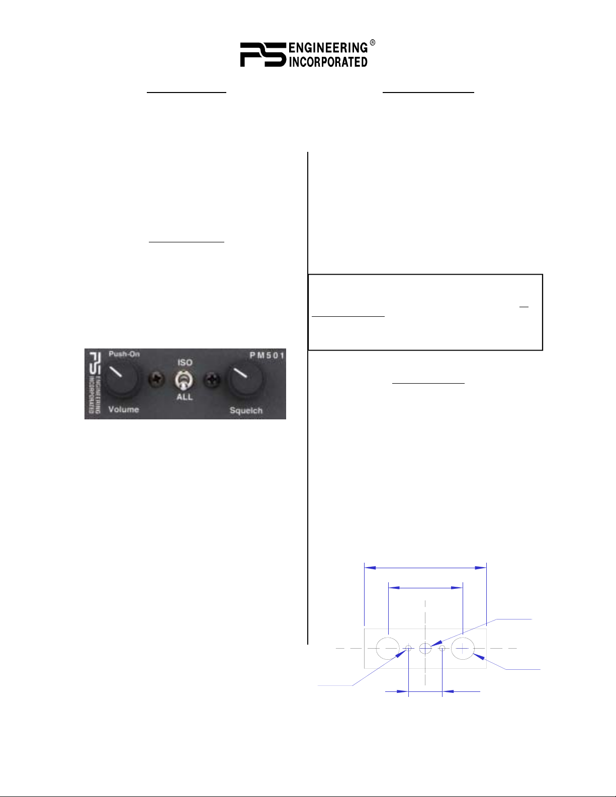
Volume
Control
CW to
Increase
Mode
Switch
PM501 Front Panel Controls
VOX Squ elch
Control CW to
increase amount of
voice necessary to
open
control clockwise increases the audio. Many headsets
have volume controls on them. If it becomes necessary
to reduce the volume for an individual passenger, the
three others should be set at maximum, and the unit
volume set for a comfortable level. The individual can
then reduce their volume accordingly.
The radio volume is not affected for the by the
PM501 Volume Control. This gives added flexibility
for communications requirements. Note
: Unit volume
is not affected by plugging in other headsets.
Adjusting The Squelch Control
This VOX operated intercom keeps all microphone channels off while the pilot, copilot or passengers are not speaking. This reduces background noise
from the aircraft. Only when someone speaks will their
microphones automatically turn on, passing the audio
through the system.
Set the Squelch control knob by slowly rotating
the squelch knob clockwise until you no longer hear
the engine noise in the earphones. When the microphone is positioned properly near your lips, normal
speech levels should open the channel. When you stop
talking, there is a delay of about a second before the
channel closes. This prevents closure between words
and eliminates choppy communications.
Mode Select
The center switch is a 2- position mode switch
that allows the pilot to tailor the intercom function to
best meet the pilot's needs. Regardless of configuration, the pilot will always hear the aircraft radio.
ISO (Up Position): The pilot is isolated from the
intercom and is connected to the aircraft radios only .
He will hear only the aircraft radio reception and sidetone (only during radio transmissions). Copilot and
passengers will hear the intercom and music but not
the aircraft radio receptions or transmissions.
PM501 Operation/Installation Manual Page 4 Revision 7, Feb 2008
Page 5

All (Down position): All parties will hear the air-
craft radio reception and transmissions, intercom, and
music. However, during any intercom activity, the
music volume automatically decreases. The music
volume increases gradually back to the original level
after communications have been completed.
The radio traffic will not mute the music.
NOTE: When either the pilot or copilot PTT is
depressed, all microphones are off except for the transmitting one.
Warranty
PS Engineering, Inc. warrants this product to be
free from defect in material and workmanship for a
period of one year from the date of sale.
Installation must be made by an authorized PS
Engineering dealer, or the installer must use a PS Engineering harness in order for the warranty to be valid.
During the warranty period, the unit must be returned to PS Engineering, Inc. and, at their option, it
will send a replacement at no charge. The customer is
responsible for shipping charges returning the unit to
PS Engineering.
This warranty is not transferable. Any implied
warranties expire at the expiration date of this warranty. WE SHALL NOT BE LIABLE FOR INCIDENTAL OR CONSEQUENTIAL DAMAGES. This
warranty does not cover a defect that has resulted from
improper or unreasonable use or maintenance as determined by us. This warranty is void if there is any attempt to dissemble this product without factory authorization.
This warranty gives you specific legal rights, and
you may also have other rights which vary from state
to state. Some states do not allow the exclusion of
limitation of incidental or consequential damages, so
the above limitation or exclusions may not apply to
your state.
Service
Call PS Engineering, Inc. at (865) 988-9800 and
ask for a technician. He may be able to diagnose the
problem and offer a solution without the possible need
for returning the unit. If the unit does need servicing,
call the factory to obtain an return authorization. Ship
product in UPS approved packaging to:
PS Engineering, Inc.
Attn.: Service Department
9800 Martel Road
Lenoir City, TN 37772
Phone: (865) 988-9800
FAX (865) 988-6619
After the warranty period, PS Engineering offers a
low flat-fee repair for the life unit. Contact the factory
for details.
PS Engineering is not responsible for units
shipped US Mail.
If no RMA, telephone number or method of pay-
ment is provided, the units will be returned COD.
Appendix A
PTT Modifications
When received from the manufacturer, aftermarket PTT switches open the microphone audio path
to the "ring" connection of the PTT mic plug. When
the PTT is between the intercom and the headset, the
intercom function will not work until the PTT switch
is depressed. A simple modification can be performed
to allow proper intercom operation. NOTE: This
modification does not alter normal operation.
Procedures For David Clark's PTT
1 Unscrew the round black plastic cover from the jack.
2 Connect the joined black wires to the red wire.
3 Replace the round black plastic cover.
Procedures for the Telex's PT-200
1 Unscrew the round black plastic cover from the jack.
2 Cut the red wire in the middle of the wire
3 Strip both ends of the insulation
4 Solder the two ends to the ground lug to the PTT jack
5 Replace the round black plastic cover
Procedures for the Telex's PT-300
1 Unscrew the round black plastic cover from the plug
jack
2 Remove the heat shrink material from the joined black
wires
3 Solder these two wires to the lug that has a white
already soldered to it.
4 Replace the round black plastic cover
These instructions represent typical after-market
switches. for more information, contact the manufacturer.
Revision 7 Feb. 2008 Page 5 200-118-0005
Page 6

Passenger 2
(p
)
Phones
Copilot PTT
Aircraft Radio PTT
Aux Mic Jack
To Aircraft Radio Phone Low
To Aircraft Radio Phone Hi
12-24 VDC
1A
11800 Sub-D DB-15 Male
AUX Headphone Jack
8
15
13
Power In
Ground
A/C Radio Phone Audio Hi
A/C Radio Phone Audio Lo
5
12
Aircraft Radio PTT
Aircraft Mic Audio Hi
To Aircraft Radio Mic Audio Lo
To A/C Radio Mic Audio Hi
Copilot Headphone Jack
14
Copilot Phones Hi
Aircraft Mic Audio Lo
7
Copilot Phones Lo
Pilot Phone Audio Hi
Passenger 1
Phones
Pilot Headphone Jack
6
Pilot Phone Audio Lo
Pass 1 and 2 Phones Hi
Pass 1 and 2 Phones Lo
Pass 1 Mic Jack
no connect
no connect
2
Pass 1 Mic Audio Hi
Pass 1 Mic Audio Lo
Copilot Mic Jack
Pass 2 Mic Jack
9
10
3
Copilot Mic PTT
Copilot Mic Audio Hi
Pass 2 Mic Audio Hi
Pass 2 Mic Audio Lo
Mic Audio Lo
Pilot PTT
Pilot Mic Jack
11
4
Pilot Mic PTT
Pilot Mic Audio Hi
Pilot Mic Audio Lo
Music Jack
9
5
7
2
2
L
I
M
o
t
m
r
1
Music Input Hi
o
f
n
o
c
t
s
u
m
e
r
i
w
l
l
A
Music Input Lo
.
1
:
S
E
T
O
N
.
e
r
i
w
d
e
d
l
e
i
h
s
h
e
t
i
g
w
a
r
g
o
t
4
c
2
u
d
m
n
u
o
m
c
-
u
3
n
i
d
M
n
.
a
0
,
0
-
5
2
7
e
2
s
r
o
U
.
2
e
r
a
s
k
y
c
l
.
d
a
l
n
j
s
e
o
k
i
e
c
h
d
n
a
s
j
n
o
l
e
h
l
p
a
m
o
n
r
o
c
o
c
i
r
s
e
m
r
t
e
n
d
i
h
n
t
s
a
a
a
e
s
w
n
d
l
g
o
.
e
n
h
i
i
d
t
p
h
e
a
s
d
t
l
.
t
a
a
u
d
c
c
e
s
i
d
n
i
s
a
e
e
h
n
r
i
i
n
u
X
n
e
q
s
o
U
e
U
C
A
r
.
.
.
3
4
5
Connector as viewed from instru-
ment panel
12345678
Microphone
Ring
(mic audi o)
9101112131415
TIP
(PTT)
Barrel
(gnd)
Barrel
(audio
gnd)
PILOT PHONES HI
12 -- 24 VDC INPUT
COPILOT PHONES HI
POWER GROUND
A/R PTT
PILOT MIC
PASS PHONES HI
A/R MIC AUDIO
A/R PHONES INPUT
Headphone
MUSIC
PASS 1 MIC
COPILOT MIC
PILOT PTT
PASS 2 MIC
COPILOT PTT
TIP
hone audi o
PM501 Operation/Installation Manual Page 6 Revision 7, Feb 2008
 Loading...