

PS Engineering PM3000 11931A, PM3000 11932, PM3000 11933A, PM3000 11934 Operation And Installation Manual
Page 1
9800 Martel Road
Lenoir City, TN 37772
PM3000
High-fidelity Stereo Intercom System
Part Number 11931A: 4-Place
and
Part Number 11932: 6-Place with
Operation and Installation Manual
FAA-TSO
C50c
Also includes 11933A, 11934, non-FAA TSO units
Document P/N 200-193-0005
Revision 8, Nov. 2013
PS Engineering, Inc. 2013 ©
Copyright Notice
Any reproduction or retransmittal of this publication, or any portion thereof, without the expressed written permission of PS Engineering, Inc. is strictly prohibited. For further information contact the Publications Manager at PS
Engineering, Inc., 9800 Martel Road, Lenoir City, TN 37772. Phone (865) 988-9800
Standard
Standard
CREW Mode
CREW
200-193-0005 Rev. 8, Nov. 2013
Page 1
Page 2

Section I General Information
1.1 Introduction
The PM3000 is an FAA-TSO approved, panel
mounted, 4- to 6-place high-fidelity stereo intercom
system (ICS). Please read this manual completely
before installation to minimize the risk of damage to
the unit and to become familiar with all the features.
1.2 Scope
This manual contains installation and operational instructions for the following PS Engineering units:
Model Description Part Number
PM3000 Standard 4-place system 11931A
PM3000 6-place system w/CREW 11932
PM3000 4-place w/recorder 11933A
PM3000 6-place w/CREW & recorder 11934
1.3 Description
The PM3000 is a 4- or 6-place (depending on model),
panel-mounted intercom with multiple volume and
VOX (voice activated squelch) circuits using unified
volume and squelch controls for the pilot, and copilot.
Passengers volume is adjusted at the headset, after
setting a master volume service adjustment on the side
of the unit.
With few controls for the pilot to use, the operation of
the PM3000 is very straightforward. Yet the unit outperforms its much more complicated competition. Although there is only one volume control knob, when an
adjustment is made to the volume control, the crew
output amplifiers are being changed simultaneously.
Likewise, when the squelch control knob is adjusted,
several VOX circuits are being changed at the same
time. Since the system is designed to use modern stereo headsets, it is not necessary to balance the volume
and squelch controls at the intercom.
A mode switch allows the pilot to select different con-
figurations. The "ALL" mode places all headsets on a
party line. In the "ISO" mode, the pilot is isolated
from all others and is connected to the aircraft radio
allowing un-interrupted radio communications.
The third mode, "CREW," included in part number
11932 (and 11934), allows the pilot and copilot to be
separated from the passengers.
The PM3000 has an automatic fail-safe interconnect to
the aircraft radios. If power is disrupted to the intercom for any reason, the pilot's headset is connected
directly to the aircraft radio allowing continued radio
communications in one earcup.
A 2-color LED is green when power is on and changes
to red when a Push to Talk (PTT or microphone key)
is pressed.
Provision for entertainment input allows the pilot, copilot and passengers the option to listen to music during flight. During intercom or aircraft radio reception,
this music will automatically mute to allow communications without distraction. When the activity ceases,
the SoftMute™ circuit gradually returns the music to
the original listening volume. By depressing the
“Mute” control (located on the Squelch knob) once, it
is possible to have the music remain at a constant
level, regardless of any ICS or radio traffic.
During various phases of flight, the degree of importance of the aircraft radio will vary. Because the "ISO"
mode connects the pilot directly to the aircraft radio,
select the "ISO" mode when the pilot must have top
priority on radio transmissions.
Both pilot and copilot have transmit capabilities over
the radio. The PM3000 only allows the voice of the
person who presses their PTT to be transmitted over
the aircraft radio. If both pilot and copilot press the
PTT at the same time, the copilot will override. When
either pilot or co-pilot presses PTT, all other microphones are disabled. The pilot can regain priority by
switching the unit off.
1.4 Approval Basis
The PM3000, part number 11931A or 11932, is FAA-
approved under TSO-C50c, and RTCA, Inc. DO-214.
Due to the fact that there is no TSO for the recorder
function in the 11933A and 11934, these units are not
TSO-approved. It is the responsibility of the installer
to determine the approval basis for these units.
1.5 Specifications
Input power: 13.8 - 27.5 Volts DC
Current : < 200 mA (Externally fused at 1 Amp)
Headphone Impedance: 150-1000 Ω (typical)
Audio Distortion: <1.2% @ 50mW into 150 Ω load
Aircraft Radio Impedance: 1000 Ω (typical)
Mic Frequency Response:±3 dB, 350 Hz — 6000 Hz
Music Frequency Response: ±3 dB, 200 Hz – 15 kHz
Unit weight: 12 Ounces (0.34 kg)
Dimensions:
1.25" H x 3.00" W x 5.50" D
(3.2 x 7.6 x 14.0 cm)
Environmental and technical qualifications:
RTCA DO-160C/DO-214
Temperature -20º to +55º C
Page 2
200-193-0005 Rev. 8, Nov. 2013
Page 3
1.6 Equipment required but not sup-
plied
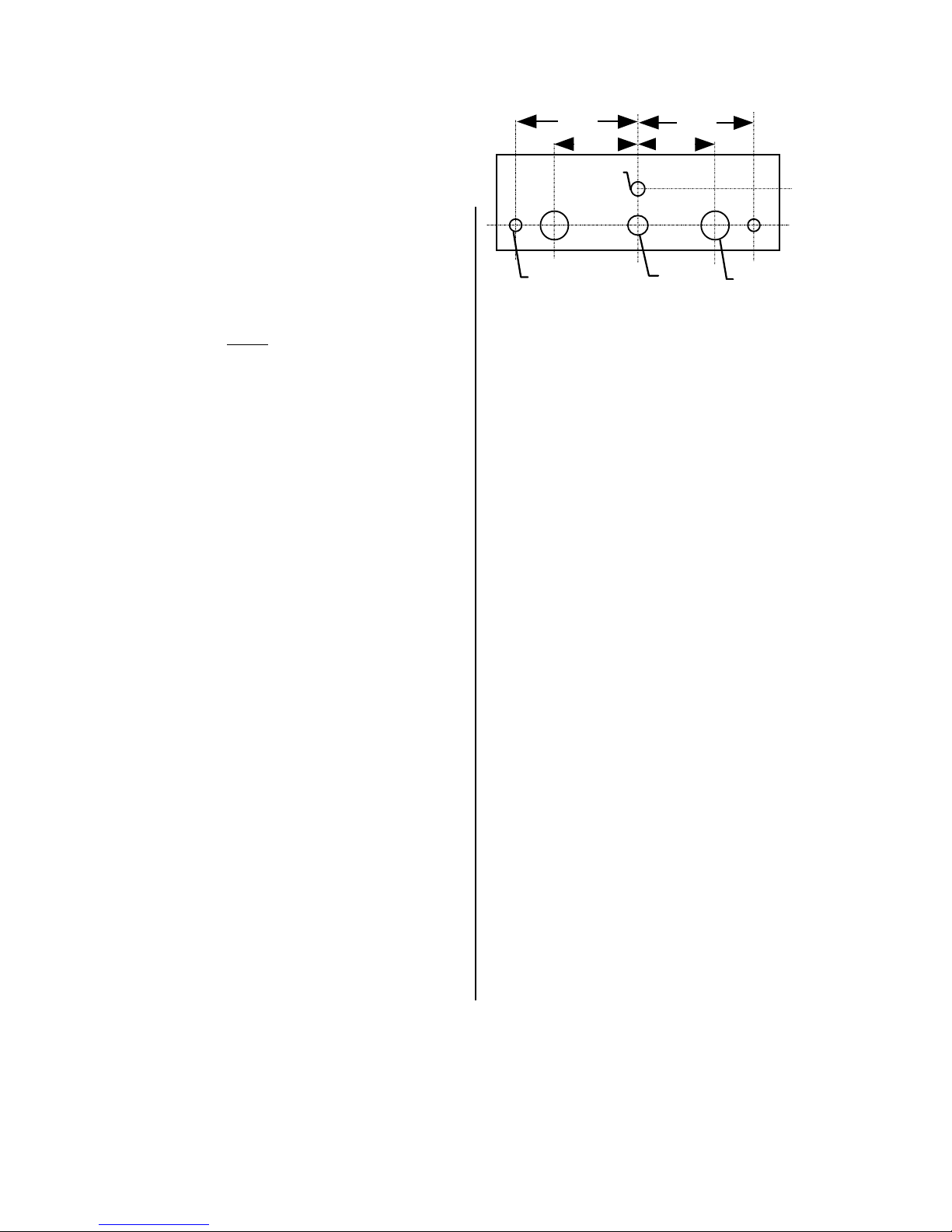
1.200
0.838 0.838
1.200
A.Interconnecting cables as required (may be ordered
from PS Engineering)
B.Headphones, 150 Ω stereo, as required
C.Microphones, general aviation, as required
D.Interconnect wiring
E.Circuit Breaker 1 Amp.
F.
Optional (see page 8):
2 ¼” Mounting Plate without
2 ¼” Mounting Plate with crew p/n 575-030-0005
crew p/n 575-030-0007
1.7 License Requirements
None
Section II Installation
2.1 General Information
The PM3000 comes with all mounting hardware and
jacks for installation. Installation of the PM3000, us-
ing the hardware supplied and available wiring does
not require special tools or knowledge other than described in FAA Advisory Circular 43.13-2B. It is the
installer's responsibility to determine the approval basis for this installation. An FAA Form 337, or other
approval may be required. See Appendix B for example of FAA Form 337.
2.2 Unpacking and preliminary inspection
The PM3000 was carefully inspected mechanically
and thoroughly tested electronically before shipment.
It should be free of electrical or cosmetic defect.
Upon receipt, verify that the parts kit includes the following:
PM3000 Installation Kits:
Part Number Description 11931A 11932 11933A 11934
475-442-0002 #4-40 screws, black 2 2 2 2
625-003-0001 Knobs (Soft Touch) 2 2 2 2
575-030-0001 Faceplate (w/crew) 1 1
575-030-0003 Faceplate (no crew) 1 1
425-025-0010 25 pin connector shell 1 1 1 1
425-020-5090 Crimp Sockets 25 25 25 25
625-025-0001 Connector hood 1 1 1 1
475-002-0002 Connector Thumbscrews 1 1 1 1
200-193-0003 Operator's Guide 1 1 1 1
122-001-0000 Drill Template 1 1 1 1
475-003-0002 Insulated Shoulder Washers 9 13 9 13
475-003-0001 Insulated Flat Washers 9 13 9 13
550-001-0002 Stereo Headphone Jack 4 6 4 6
550-001-0003 Microphone Jack 4 6 4 6
550-008-0001 Music Input Jack ⅛” 1 2 1 2
550-005-0001 Playback Plug 3.3mm 1 1
0.250
0.325
2 ea. 0.125
NOT TO SCALE
0.297
2 ea. 0.314
2.3 Equipment installation procedures
Figure 1 Hole Spacing
1. Using the template, drill six holes in the instrument
panel in a location convenient to the pilot position
(s).
2. Insert the PM3000 from behind the instrument
panel, aligning the holes for the knobs, LED, and
switch.
3. Place the aluminum plate over the knob shafts and
secure, using the two # 4-40 round head screws provided.
4. Install the knobs over the volume and squelch control shafts.
5. Complete a wiring harness in accordance with Appendix D.
2.4 Cable harness wiring
To complete the installation, a wire harness must be
made as shown in Appendix D.
Note:
PS Engineering can make a custom-tailored wiring harness for the installer. All harnesses use
Mil-spec quality components with professional
techniques, and are fully tested before shipment.
Contact PS Engineering for more information,
www.ps-engineering.com.
If the aircraft already has pilot headset jacks installed,
you may re-use one mono set for the AUX (radio )
jacks but they should be moved to a new location to
avoid confusion with the pilot's headphone jacks. In
the event the intercom has to be removed for any reason, these jacks provide access to the aircraft radio
system. Remove and discard copilot headset jacks if
these are monaural.
To connect intercom into the aircraft audio system,
parallel the appropriate set of cables from the intercom
to the Auxiliary Aircraft Radio Headset Jacks. Finally,
install new pilot, copilot and passenger headset jacks
200-193-0005 Rev. 8, Nov. 2013
Page 3
Page 4

into the aircraft and connect them directly to the ap-
propriate pins of the PM3000. See the wiring diagram
for all details of the wire harness interconnect.
2.4.1 Electrical Noise Issues
WARNING: You must use individual shielded cables
for the microphone and headphone jacks. Combining
these two wires WILL cause loud oscillations and degrade the intercom function. The oscillation is caused
by the cross-coupling between the large headphone
signal and the small microphone signal. The resulting
feedback is a high-pitched squeal that varies with the
volume control.
Due to the variety of the radio equipment found in
today's general aviation aircraft, there is the potential
for both radiated and conducted noise interference.
The PM3000 has a specially designed power supply to
reduce conducted electrical noise on the power bus of
the aircraft by at least 50dB. Although this is a very
large amount of attenuation, it does not eliminate all
noise when the amount is excessive. There must be at
least 13.75 Volts DC present at the PM3000 for the
power supply to work within its optimum regulation.
Otherwise, it will not be able to attenuate noise properly.
Shielding can protect the system from radiated noise
(rotating beacon, electric gyros, switching power supplies, etc.). However, installation combinations can
occur where minor interference is possible. The
PM3000 was designed in an interference -protected
chassis and has internal filter capacitors on all input
lines.
Ground loop noise occurs when there are two different
return paths for the same signal, such as airframe and
ground return wire. Large cyclic loads such as strobes,
inverters, etc., can inject audible signals onto the airframe return path. Follow the wiring diagram very
carefully to help insure a minimum of ground loop
potential. Radiated signals can be a factor when low
level microphone signals are bundled with current carrying power wires. Keep these cables separated.
Insulating washers are required
headphone jacks to isolate them from aircraft ground.
The use of a conductor instead of a shield for ground
return eliminates these ground loop paths.
on all microphone and
2.4.2 Power & Dimmer
The PM3000 was designed to work with 12.8 to 27.5
volt DC negative ground systems. The PM3000 must
be externally protected with a one ampere (1A) circuit
breaker or fuse.
[11931A & 11933A] Connect Pin 5 to the aircraft
dimmer bus. This will adjust the Power/Xmit LED for
varying lighting conditions. If no connection is made,
the LED will be at maximum brightness.
The unit is shipped for 14 VDC dimmer systems. For a
28 VDC aircraft dimmer system, open the PM3000
case and remove the Jumper J2.
2.4.3 Unswitched Audio Input
The PM3000, P/N 11931A & 11933A have two
unswitched audio inputs available for 500Ω aviation
audio sources. Pin 17 is Unswitched #1, and is also
provided to the pilot in Fail-Safe Mode. Unswitched
#2 input is Pin 4.
2.4.4 Sidetone
The PM3000 can be modified to produce sidetone
(hearing your voice during transmit), if the aircraft
radios do not produce it. Contact the PS Engineering
factory for details.
2.4.5 Entertainment Input
Stereo entertainment devices can be connected to the
PM3000. Install ⅛" stereo jacks convenient the pilot
and passengers to connect the entertainment devices
into the system. PM3000, part number 11931A has a
single entertainment input. The part number 11932
will accommodate two inputs, one for the crew, and
another separate input that feeds the 4 passengers in
CREW mode.
It is possible to use only one entertainment device to
Use only low level output of the entertainment devices
to connect to the PM3000. Maximum signal level on
the input is 2-volts peak-to-peak.
DO NOT USE
OUTPUT LEVELS.
This will cause internal damage.
provide music for both inputs in the 11932 system by
connecting the output of the entertainment device in
parallel to both the Music #1 and Music #2 inputs. We
highly recommend, however, that you install a switch
between the entertainment device and Music #1. This
will give the pilot and copilot the ability to switch off
music while in the CREW mode.
The music device will automatically mute when the
ICS or aircraft radio becomes active. The Soft Mute™
feature slowly returns the music to full volume when
the activity ceases. Pressing the Mute disable switch
If speaker levels are to be used, install an
Audio Link, p/n 101PL2,
available from Crutchfield (1-800-955-3000).
SPEAKER
Page 4
200-193-0005 Rev. 8, Nov. 2013
Page 5

(located on the squelch control) in will inhibit this feature. Press again to reactivate SoftMute. Music #2
will never be muted during conversation and is heard
only by the passengers while the intercom is in the
Crew mode.
2.4.6 Passenger Volume Adjustment
The 6-place PM3000 (11932, 11934) has adjustments
for passenger volume control. These are accessed
through the left side of the unit (viewed from the
front). There is a separate volume control for the left
and right channels. The left adjustment is toward the
front, and clockwise adjustment reduces passenger
volume.
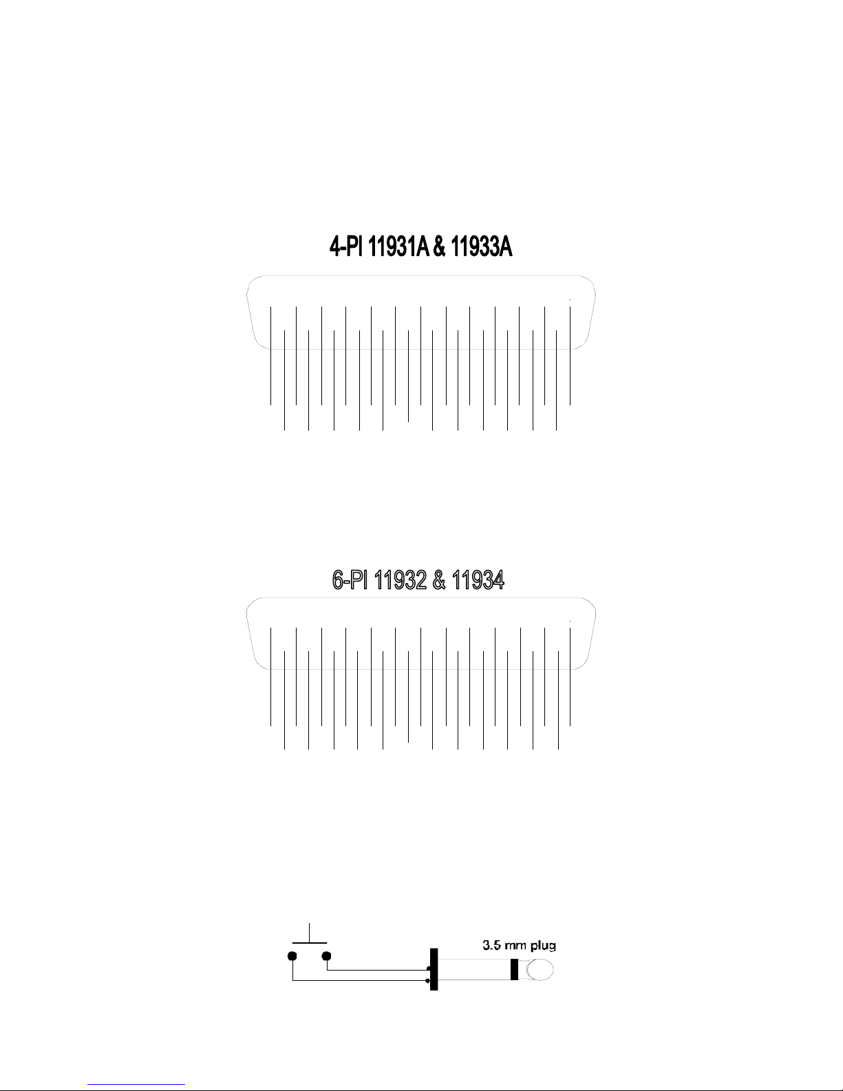
2.4.7 Internal Recorder (11933A, 11934 only)
PM3000 part number 11933A and 11934 have an internal recorder that stores recent incoming radio messages. A 3.5 mm jack is provided on the rear of the
intercom unit to interface this function. Install a momentary, normally open (NO), switch in a location
convenient to the pilot, and wire to the 3.5 mm plug
(included) across the tip and sleeve contacts. Closing
this switch will activate the playback. A low-current
rated switch is recommended.
2.4.8 Monaural installations
The PM3000 can be installed as a monaural intercom.
Connect the RIGHT channel to the headsets (this contains failsafe audio). Do NOT combine left and right
headphone outputs.
2.4.9 External PTT hook-up
Part of the installation includes the installation of PTT
(Push-to-Talk) switches that allow radio transmissions
from pilot and copilot positions.
There are three configurations that can be used. You
must select the case that best fits your installation.
NOTE
: Only the person who presses their PTT switch
will be heard over the radio.
CASE I-The PTT is built into the pilot and copilot
yokes
Simply install the plugs from the headset into the aircraft headphone jacks. Then use the yoke mounted
PTT to transmit. No other action is required.
CASE –II Built in PTT only on the pilot side
This configuration requires a modified external PTT
switch plugged into the copilot's mic jack. (See Appendix A) When the copilot's PTT is depressed, this
activates an internal relay that switches the mic audio
to the aircraft radio from the pilot to the copilot.
Case III -No built in PTT switch at all.
Two built-in PTT must be installed or two external,
modified PTT switches will be required for both the
pilot and copilot. Modifications to the PTT may be
required. (See Appendix A)
2.5 Post installation checkout
After wiring is complete, verify aircraft power is
ONLY on pin 13 of the connector, and airframe
ground on pin 1. Other voltages may be present on the
incoming mic lines. Wiring errors can cause serious
internal damage and void PS Engineering's warranty.
1. Apply power to the aircraft and avionics.
2. Plug headsets into the pilot, copilot and passenger
positions.
3. Verify that the pilot position can transmit and re-
ceive with the PM3000 in the OFF position (left
hand knob controls on/off by push on-push off).
4. Push the volume knob to switch the PM3000 on.
Rotate the volume clockwise, about half way. Ver-
ify that the Pwr/Xmt light comes on green. If the
LED is red, immediately switch off the avionics,
and troubleshoot the PTT installation.
5. Verify that the pilot can transmit and receive on the
communications transceivers.
6. Verify proper intercom operation for pilot, copilot
and passengers. For more information, consult Section 3.
7. Verify proper transmit and receive operation on the
copilot position, noting that the copilot PTT switch
allows proper transmission.
8. Verify proper Intercom system operation in the
ALL, ISO (and CREW in part number 11932,
11934) modes.
9. Verify that the intercom system does not adversely
affect any other aircraft system by systematically
switching the unit on and off, while monitoring the
other avionics and electrical equipment on the aircraft.
10. Recorder Check Out (11932A, 11934 only) Tune
a communications radio to an active 2-way channel, (not AWOS or ATIS). Listen for a radio transmission. When it is concluded, press the
“Playback” button and verify that the last message
plays in the pilot headset.
200-193-0005 Rev. 8, Nov. 2013
Page 5
Page 6
Section III OPERATION
With the installation is complete, turn the PM3000 on
by pushing the volume control. This also engages the
automatic fail-safe system. The intercom volume control does not control the volume of the aircraft radio,
allowing an additional degree of aircraft radio listening
flexibility.
intercom volume to be balanced independently. The
volume control affects the music level for the pilot and
copilot positions.
By turning the control clockwise, the audio level will
increase. The PM3000 has individual output amplifi-
ers for each headset in the system and provides plenty
of audio output power. NOTE: Volume level will not
change with the number of headset installed.
Music # 2 passenger volume in CREW mode (11932
and 11934) version is a fixed level, and controlled
locally by the headphone volume control or music
device.
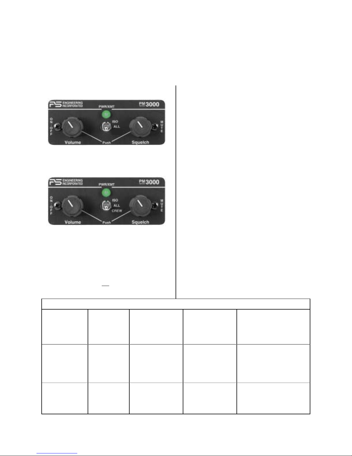
3.2 Adjusting the Squelch Control
Figure 2 PM3000 (11931A, 11933A) front panel
controls
channels off (silent) while the pilot, copilot or passengers are not speaking. This reduces background noise
from the aircraft. Only when someone speaks will their
microphone turn on, allowing the audio to pass
through the system. Although there is just one squelch
control, there are actually three separate squelch
threshold circuits. One circuit each for the pilot, copilot, and passengers. Only the microphone actually in
use is open, reducing noise in the system.
With the engine running, set the squelch control knob
by slowly rotating the squelch control knob clockwise
This VOX operated intercom keeps all microphone
Figure 3 PM3000 (11932, 11934) front panel con-
trols
until you no longer hear the background noise in the
earphones. When the microphone is positioned properly near the lips, normal speech levels should open
3.1 Adjusting the Volume
The PM3000 volume control knob adjusts the loud-
ness of the intercom and music only. The volume control on the PM3000 does not
affect the volume level of
the channel. When you have stopped talking, there is a
delay of about one half second before the channel
closes. This prevents squelch closure between words,
and helps eliminate choppy intercom conversations.
the aircraft radio. This allows the aircraft radio and
Mode Pilot Hears Copilot Hears Passenger Hears Comments
Isolate A/C Radio,
Pilot Sidetone
(during radio trans-
mission)
Copilot and passenger
intercom,
Music #1
Passenger and Copilot
intercom,
Music #1
This mode allows the pilot to communicate with the ground without the
copilot or passengers bothered by the
conversations. Copilot and passengers
continue to communicate and listen to
music #1
All Pilot,
Copilot,
A/C Radio,
Passengers,
Music #1
Crew
(11932 11934 only)
Pilot,
Copilot,
A/C Radio
Entertainment #1
Copilot,
Pilot,
A/C Radio,
Passengers,
Music #1
Copilot,
Pilot,
A/C Radio
Entertainment #1
Page 6
Passengers,
Pilot,
Copilot,
A/C Radio,
Music #1
Passengers,
Entertainment #2
This mode allows all on board to hear
radios as well as communicate on the
intercom. Music and intercom is muted
during intercom and radio communications
A second music source is automatically enabled for the passengers. Rear
music not muted.
200-193-0005 Rev. 8, Nov. 2013
Page 7

3.3 Mode Select
The center switch is a mode control that allows the
pilot to tailor the intercom function to suit flight conditions. Regardless of configuration, the pilot will always hear the aircraft radio. NOTE: If there is a
power failure to the PM3000, or if the power switch is
turned off, the copilot will not hear the aircraft radio.
Only the pilot is connected directly to the aircraft radio.
ISO (Up Position): The pilot is isolated from the inter-
com and is connected only to the aircraft radios. He
will hear the aircraft radio reception (and sidetone during radio transmissions). Copilot and passengers will
hear themselves and music but not the aircraft radio
traffic.
ALL (Middle position): All parties will hear the air-
craft radio, intercom, and music. However, during any
ICS conversation, the music volume automatically
mutes. The music volume increases gradually back to
the original level after communications have been
completed.
CREW (11932, 11934 only) (down position): Pilot
and copilot positions will hear aircraft radio and music
number one. Passengers will only hear other passenger’s intercom, and music number 2. Music number
two will not mute during intercom conversation.
3.4 Music Mute Control
Normally, any radio traffic or intercom conversation
will mute the music heard in ALL mode, or for the
front in CREW. However, when the crew desires uninterrupted music, the PM3000 can be placed in the
Karaoke Mode, for singing along. Press the right knob
(squelch) once to activate Karaoke mode, so the music
will not be muted. Press again to restore the SoftMute
function.
Local oscillators and other internal signals from
CD or radio equipment can cause undesired inter-
ference with VHF navigation and communication
equipment.
Before takeoff, operate the entertainment device to
determine if there is any adverse effect on aircraft
systems. If any unusual operation is noted in flight,
immediately switch the entertainment device off
3.5 Internal Recording System (11933A,
11934 only)
This records the last radio messages, storing up to 60
seconds of received radio phrases. Only the pilot will
hear the playback. The last message received will be
the first one played back. This function is intended to
help the pilot determine is a radio call was meant for
him, and not to store clearance or ATIS.
To play back the last recorded message, press the
switch labeled “Playback” installed in the aircraft. To
cancel the playback, press and hold the playback button for two seconds. The next time the button is
pressed, the earlier message will be heard. If the radio
becomes active while a message is playing, the message playback will stop. The new audio will not be
stored. Press play to restart the message you were
playing.
A radio signal of more than 1 VRMS is needed to
trigger the IRS. Therefore, if the IRS does not seem
to be recording, increase the aircraft radio volume.
Section IV Warranty and service
4.1 Warranty
In order for the factory warranty to be valid, the installations in a certified aircraft must be accomplished
by an FAA-certified avionics shop and authorized PS
Engineering dealer. If the unit is being installed by a
non-certified individual in an experimental aircraft, a
factory-made harness must be used for the warranty
to be valid.
PS Engineering, Inc. warrants this product to be free
from defect in material and workmanship for a period
of one year from the date of sale. During this oneyear warranty period, PS Engineering, Inc., at its option, will send a replacement unit at our expense if
the unit should be determined to be defective after
consultation with a factory technician.
This warranty is not transferable. Any implied warranties expire at the expiration date of this warranty.
PS Engineering SHALL NOT BE LIABLE FOR INCIDENTAL OR CONSEQUENTIAL DAMAGES.
This warranty does not cover a defect that has resulted from improper or unreasonable use or maintenance as determined by us. This warranty is void if
there is any attempt to dissemble this product without
factory authorization. This warranty gives you specific legal rights, and you may also have other rights,
which may vary from state to state. Some states do
not allow the exclusion of limitation of incidental or
consequential damages, so the above limitation or
exclusions may not apply to you.
200-193-0005 Rev. 8, Nov. 2013
Page 7
Page 8

4.2 Factory Service
The PM3000 is covered by a one-year limited war-
ranty. See warranty information.
Call PS Engineering, Inc. at (865) 988-9800 before
you return the unit. This will allow the service technician to provide any other suggestions for identifying
the problem and recommend possible solutions.
Information is also available by visiting www.psengineering.com/support.shtml
Units that arrive for repair without a method of payment will be returned via UPS COD.
After discussing the problem with the technician and
you obtain a Return Authorization Number, ship product to:
NOTE: PS engineering will not be responsible for any units sent
by US Mail.
PS Engineering, Inc.
Service Department
9800 Martel Road
Lenoir City, TN 37772
(865) 988-9800 FAX (865) 988-6619
Appendix A — PTT Modifications
When received from the manufacturer, an aftermarket
PTT switch opens the mic audio path to the "ring"
connection of the PTT mic plug. When the PTT is between the intercom and the headset, the intercom function will not work until the PTT switch is depressed. A
simple modification can be performed to allow proper
intercom operation. NOTE: This mod does not alter
normal operation. Modified portable PTT switches are
available from PS Engineering. Call 1-800-ICS-AERO
to order.
Interface to existing aircraft radios in accordance
with manufacturer’s installation manual and in
compliance with practices listed in AC43.13-2B,
Chapter 2. All wires are Mil-Spec 22759 or
27500. No connection to the aircraft dimmer bus
is required. Power is supplied to the unit through a
1A circuit breaker (type and part number
total electrical load does not exceed % of the
electrical system capacity with the PM3000
added.
Aircraft equipment list, weight and balance
amended. Compass compensation checked. A
copy of the operation instructions, contained in PS
Engineering document 202-193-xxxx, revision (x),
(date) , is placed in the aircraft records. All work
accomplished listed on Work Order
.
), and
Appendix C, Instructions for continuing airworthiness
The PM3000 is considered an “on-condition” mainte-
nance item. It is checked prior to each flight during
normal operation. There are no additional considerations for continuing airworthiness other than the practices detailed in AC 43.13-1B, Chapter 11. This includes inspecting the unit to be sure it is securely fastened in its location, and that the wiring harness is not
chafed or pinched, and remains secure. All panel jacks
should be checked at each periodic inspection to ensure that they are tight and not in contact with other
items behind the instrument panel.
Appendix B- Instructions for FAA
Form 337
One method of airworthiness approval is through
an FAA Form 337, Major Repair and Alteration
(Airframe, Powerplant, Propeller, or Appliance)
In the case of the PM3000, you may use the following text as a guide.
Installed x-place intercom, PS Engineering
PM3000, part number 1193(_) in ( location )
station .
stalled per PS Engineering Installation Operators
Manual p/n 200-193-xxxx, revision x, dated ( ).
This unit is FAA-Approved under TSO C50c for
audio amplifiers, and meets environmental tests
outlined in RTCA DO-160C as appropriate or this
aircraft.
Installed per AC43.13-2B, In-
at
Optional 2 ¼” Mounting Plate without crew –575-030-0007
Optional 2 ¼” Mounting Plate with crew 575-030-0005 (shown)
Page 8
200-193-0005 Rev. 8, Nov. 2013
Page 9
Appendix D– Wiring Information
DB 25 Unit Connectors
12345
14 15 16 17 18
Ground
Pass 2 Mic Hi
Copilot Mic Hi
Pass 1 Mic Hi
A/C Radio Input
Lighting Control
Copilot PTT
Unswitched Input 2
Unswitched Input 1
12345
14 15 16 17 18
6789
19 20 21 221023 24
Pilot PTT
Music Lo
Pass 1 Audio (R)
Pass 2 Phones (R)
Pass 2 Phones (L)
Pilot Phones (R)
Copilot Phones (R)
Pass 1 Audio (L)
Pilot Phones (L)
Copilot Phones (L)
6789
19 20 21 221023 24
11 122513
Music Input (R)
A/C Radio PTT
Music Input (L)
Power (11-33 VDC)
Pilot Mic Audio Hi
A/C Mic Audio Hi
11 122513
Ground
200-193-0005 Rev. 8, Nov. 2013
Pilot PTT
Pass 2 Mic Hi
Copilot Mic Hi
Copilot PTT
Pass 1 Mic Hi
A/C Radio Input
Pass 4 Mic Hi
Pass 3 Mic Hi
Music Input 2 (R)
Pass 2&4 Phones (R)
Music Input 2 (L)
Pass 2&4 Phones (L)
Pilot Phones (R)
Copilot Phones (R)
Pass 1&3 Audio (R)
Pass 1&3 Audio (L)
Pilot Phones (L)
Copilot Phones (L)
A/C Radio PTT
Music Input 1 (R)
Music Input 1 (L)
Pilot Mic Audio Hi
Recorder Playback Connection (11933A, 19934)
Page 9
Power (11-33 VDC)
A/C Mic Audio Hi
Page 10

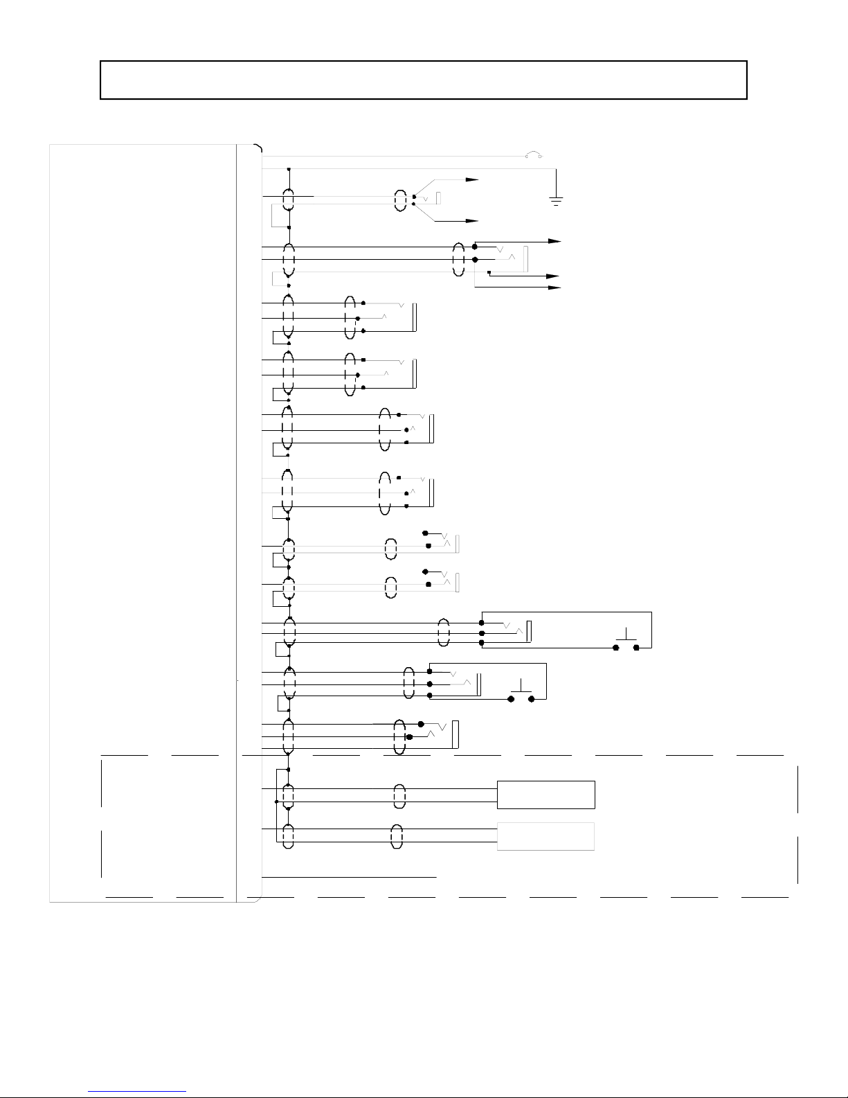
PM3000 (11932, 11934) w/Crew, 6-place wiring diagram
PM3000 Sub-D DB-25 Male
Power In
Ground
A/C Radio Phone Audio Hi
A/C Radio Phone Audio Lo
A/C PTT
A/C Mic Audio Hi
A/C Mic Audio Lo
Pilot Phones (L)
Pilot Phones (R)
Pilot Phones Lo
1
14
12
25
22
9
To Aircraft Radio
Phone Audio Hi
AUX Headphone
Jack
To Aircraft Radio
Phone Low
Pilot Headphone Jack
11-33 VDC13
1A
Aux Mic Jack
Aircraft Radio PTT
To Aircraft Radio Mic Audio Lo
To A/C Radio Mic Audio Hi
N
O
T
E
:
S
Copilot Phone Audio (L)
Copilot Phone Audio (R)
Copilot Phone Audio Lo
Pass 1 & 3 Phone Audio (L)
Pass 1 & 3 Phone Audio (R)
Pass 1 Phone Audio Lo
Pass 2 & 4 Phones Audio (L)
Pass 2 & 4 Phones Audio (R)
Pass Phones Audio Lo
Pass 1 Mic Audio Hi
Pass 1 Mic Audio Lo
Pass 2 Mic Audio Hi
Pass 2 Mic Audio Lo
Copilot Mic PTT
Copilot Mic Audio Hi
Mic Audio Lo
Pass 3 Mic Audio Hi
Pass 3 Mic Audio Lo
Pass 4 Mic Audio Hi
Pass 4 Mic Audio Lo
Pilot Mic PTT
Pilot Mic Audio Hi
Pilot Mic Audio Lo
Music #1 (L)
Music #1 (R)
19
6
15
2
5
18
10
23
21
8
20
7
16
3
24
11
Copilot Headphone Jack
Passenger 1
Headphone
Passenger 2
Headphone
Pass 1 Mic
Pass 2 Mic
Pilot Mic Jack
Entertainment #1 Input
SEE NOTE 6
Copilot Mic Jack
Pass 3 Mic
Pass 4 Mic
Pilot PTT
Passenger 3
Headphone
Passenger 4
Headphone
Copilot PTT
SEE NOTE 6
Music #2 (L)
Music #2 (R)
Notes:
1. All wire must conform to MIL-22759 or 27500. Minimum 24 gage shielded wire.
2. Use 2-, and 3-, conductor with shield as indicated.
3. Use insulating washers on all jacks. Jacks must be electrically floating.
4. Connect shields at intercom end only
5. AUX headphone and microphone jacks are required.
6. For 11931 and 11933, do not connect passenger 3 & 4, or Music 2 inputs.
17
4
Page 10
Entertainment #2 Input
SEE NOTE 6
200-193-0005 Rev. 8, Nov. 2013
Page 11
PM3000 (11931A& 11933A) 4-Place Standard Intercom (Without Crew) Wiring Diagram
PM3000 Sub-D DB-25 Male on unit
Power In
Ground
A/C Radio Phone Audio Hi
A/C Radio Phone Audio Lo
A/C PTT
A/C Mic Audio Hi
A/C Mic Audio Lo
Pilot Phones (L)
Pilot Phones (R)
Pilot Phones Lo
Copilot Phone Audio (L)
Copilot Phone Audio (R)
Copilot Phone Audio Lo
Pass 1 Phone Audio (L)
Pass 1 Phone Audio (R)
Pass 1 Phone Audio Lo
Pass 2 Phones Audio (L)
Pass 2 Phones Audio (R)
Pass Phones Audio Lo
1
14
12
25
22
9
21
8
20
7
19
6
To Aircraft Radio
Phone Audio Hi
AUX Headphone
Jack
To Aircraft Radio
Phone Low
Aux Mic Jack
Pilot Headphone Jack
Copilot Headphone Jack
Passenger 1
Headphone
Passenger 2
Headphone
1A
11-33 VDC13
Aircraft Radio PTT
To Aircraft Radio Mic Audio Lo
To A/C Radio Mic Audio Hi
N
O
T
E
S
:
1
.
w
l
A
l
r
i
e
u
m
s
o
t
c
2
o
r
5
7
2
s
U
.
2
e
a
s
d
i
n
U
3
.
n
i
e
s
m
s
t
u
C
4
.
n
n
o
A
5
.
X
U
h
u
e
q
r
r
i
.
6
s
n
U
w
.
7
o
r
F
8
2
8
i
n
.
P
1
8
9
.
o
C
e
n
n
P
1
8
n
i
n
I
1
1
9
n
0
M
0
.
n
u
i
m
-
a
n
,
-
3
d
c
o
,
e
a
i
t
c
d
.
u
l
s
g
t
n
i
a
a
w
b
e
e
e
c
l
c
t
a
i
r
t
e
c
e
h
i
s
a
s
l
d
a
e
p
h
d
e
o
n
e
i
d
.
t
c
d
h
e
i
1
#
s
i
d
V
e
m
m
,
r
m
s
i
i
u
c
s
f
o
l
o
i
c
t
n
i
s
n
d
a
m
s
i
s
u
l
i
o
c
&
3
1
1
1
3
9
3
o
r
f
t
m
o
L
I
M
2
2
-
9
7
m
u
4
2
n
u
c
d
e
s
h
s
r
f
l
l
l
y
a
o
t
n
t
i
e
n
d
a
m
p
r
v
i
o
r
e
o
m
a
n
g
i
t
d
e
s
h
n
i
w
1
t
n
i
u
s
5
a
g
g
h
s
e
d
e
l
i
w
e
d
.
r
i
r
w
t
o
i
h
t
s
n
o
l
l
a
a
j
n
i
t
.
g
o
r
c
m
e
n
i
c
h
o
p
r
n
o
d
t
d
e
i
p
o
J
e
v
u
p
m
w
o
l
e
a
r
f
o
a
r
9
1
A
3
1
(
o
c
n
e
n
c
t
e
e
h
i
d
l
k
c
a
.
J
s
k
s
c
o
d
y
l
n
e
c
j
a
a
s
k
r
e
l
t
H
o
i
S
n
s
l
i
f
a
f
e
a
2
e
r
m
r
f
o
n
s
i
e
i
d
t
n
i
u
.
1
1
3
1
9
&
A
1
9
1
A
3
3
y
n
l
o
1
1
A
3
3
9
.
)
t
o
i
u
n
o
g
r
t
d
u
n
.
n
p
i
,
.
1
Pass 1 Mic Audio Hi
Pass 1 Mic Audio Lo
Pass 2 Mic Audio Hi
Pass 2 Mic Audio Lo
Copilot Mic PTT
Copilot Mic Audio Hi
Mic Audio Lo
Pilot Mic PTT
Pilot Mic Audio Hi
Pilot Mic Audio Lo
Music (L)
Music (R)
Music Lo
Unswitched Audio 1
Unswitched Audio 2
Lighting control
15
2
16
3
10
23
24
11
18
17
Pass 1 Mic
Pass 2 Mic
Copilot Mic Jack
Copilot PTT
Pilot Mic Jack
Pilot PTT
Entertainment Input
See note 8
Unswitched
See note 6
Audio 1
4
Unswitched
Audio 2
5
Dimmer Connection (14/28V)
Note 9:
CONNECTIONS FOR P/N 11931A
& 11933A ONLY
See Note 7
200-193-0005 Rev. 8, Nov. 2013
Page 11
Page 12

RTCA DO-160C Environmental Qualification: Form
Nomenclature: Intercom, stereo, panel mounted
Unit Type: PM3000 Part Number: 11932 FAA TSO Number: C50c
Manufacturer: PS Engineering Incorporated
9800 Martel Road Lenoir City TN 37772
Conditions Section Conducted Tests
Temperature and Altitude
Low Temperature
High Temperature
In-flight Loss of Cooling
Altitude
Decompression
Overpressure
Temperature variation
4.0
4.5.1
4.5.2
4.5.4
4.6.1
4.6.2
4.6.3
5.2 Equipment tested to Category C
Equipment tested to CAT A1 &
D1
-20° C Storage, -15°C Low Operating
+85°C Storage, +70°C High Op-
erating
Not Applicable, no cooling re-
quired
Humidity
Shock
Operational
Crash Safety
Vibration
Explosion
Waterproofness
Fluids Susceptibility
Sand and Dust
Fungus
Salt Spray
Magnetic Effect
Power input
Voltage Spike
Audio Frequency Susceptibility
6.0 Equipment tested to Category A
7.0 Equipment tested to Operational
7.2 Equipment tested to Operational
7.3 Equipment tested to Operational
8.0 Equipment tested to Category M
9.0 Category X, not tested
10.0 Category X, not tested
11.0 Category X, not tested
12.0 Category X, not tested
13.0 Category X, not tested
14.0 Category X, not tested
15.0 Equipment tested to Category Z
16.0 Equipment tested to Category B
17.0 Equipment tested to Category B
18.0 Equipment tested to Category B
Induced Frequency Susceptibility
Radio Frequency Susceptibility
Radio Frequency Emission
Lightning Induced Transient Susceptibility
Lightning Direct Effects
Icing
Page 12
19.0 Equipment tested to Category B
20.0 Equipment tested to Category J
21.0 Equipment tested to Category B
22.0 Equipment tested to Category K
23.0 Category X, not tested
24.0 Category X, not tested
200-193-0005 Rev. 8, Nov. 2013
 Loading...