

Page 1

9800 Martel Road
Lenoir City, TN 37772
PM2CREW Intercom Expansion Unit
Unit Part Number 11918, 11918R,
11918P6, 11918R6
11918P8, 11918R8
Passenger Intercom System
Installation and Operation Manual
Document P/N 200-005-0004
Revision 4 Sept. 2000
PS Engineering, Inc. 2000 ©
Copyright Notice
Any reproduction or retransmittal of this publication, or any portion thereof, without the expressed
written permission of PS Engineering, Inc. is strictly prohibited. For further information contact the
Publications Manager at PS Engineering, Inc., 9800 Martel Road, Lenoir City, TN 37772. Phone
(865) 988-9800 www.ps-engineering.com
Page 2

PS Engineering
PM2Crew Expansion module (11918)
Table of Contents
SECTION I GENERAL INFORMATION 1-2
1.1 I
1.2 S
1.3 D
1.4 A
1.5 S
1.6 E
NTRODUCTION 1-2
COPE 1-2
ESCRIPTION 1-2
PPROVAL BASIS 1-2
PECIFICATIONS 1-2
QUIPMENT REQUIRED BUT NOT SUPPLIED 1-2
SECTION 2 INSTALLATION 2-1
2.1 G
2.2 U
2.3 E
2.4 C
2.4.1 E
2.4.2 P
2.4.3 I
2.4.4 S
2.4.5 A
ENERAL INFORMATION 2-1
NPACKING AND PRELIMINARY INSPECTION 2-1
QUIPMENT INSTALLATION PROCEDURES 2-1
ABLE HARNESS WIRING 2-2
LECTRICAL NOISE ISSUES 2-2
OWER REQUIREMENTS 2-3
NTERCONNECTION WITH MAIN UNIT 2-3
IX AND EIGHT PLACE UNITS (11918P6 AND 11918R6, 11918P8 AND 11918R8) 2-3
UXILIARY INPUTS 2-3
SECTION III OPERATION 3-4
3.1 A
3.2 A
DJUSTING THE VOLUME 3-4
DJUSTING THE SQUELCH CONTROL 3-4
SECTION 4 WARRANTY AND SERVICE 4-4
4.1 W
4.2 F
ARRANTY 4-4
ACTORY SERVICE 4-4
APPENDIX B INSTRUCTIONS FOR FAA FORM 337 A
APPENDIX D WIRING INFORMATION B
Revision 3: Added remote pot information
Revision 4: Added 8-place
200-004-0004 Page i Rev. 4, Sept. 2000
Page 3

PS Engineering
PM2Crew Expansion module (11918)
Section I General Information
1.1 Introduction
The PM2Crew is a panel mounted, multi-place intercom expansion unit used to add extra stations to an
intercom system. Please read this manual completely before installation to minimize the risk of damage to
the unit and to become familiar with all the features.
1.2 Scope
This manual contains installation and operational instructions for the following PS Engineering units:
Model Description Part Number
PM2CREW 4-place intercom expansion unit system 11918
PM2CREW Remote Blind-mount expansion unit w/remote squelch 11918R
PM2CREW 6-place intercom expansion unit system 11918P6
PM2CREW Remote 6-place blind-mount expansion unit 11918R6
PM2CREW 8-place intercom expansion unit system 11918P8
PM2CREW Remote 8-place blind-mount expansion unit 11918R8
1.3 Description
The PM2CREW (11918) is an intercom expansion unit with volume and squelch controls for the
passengers. This unit is designed to work in combination with the PM1000 (11900, 11900D), PM1000II
(11902, 11922, 11906), PM2000 (11915) intercoms and PMA4000 Audio Panel to provide 4 or 6
additional passenger stations. The part number 11918R is designed for remote, or blind mounting. A
remote squelch control is provided to adjust the VOX threshold, the volume control is factory set for
optimum level.
The 11918P6 and 11918R6 are 6-place expansion units. The 11918P8 and 11918R8 are 8-place expansion
units.
1.4 Approval Basis
None.
It is the installer’s responsibility to determine the applicable approval basis for this installation. This unit is
not designed for use in any flight crew situations, and has no effect on any critical aircraft systems. There
is no significant weight or electrical load presented to the aircraft. The unit can be installed without any
special tools or knowledge.
1.5 Specifications
Input power: from main unit
Headphone Impedance: 150-1000 Ω typical
Audio Distortion: <10% @ 75 mW into 150 Ω load
Aircraft Radio Impedance: 1000 Ω typical
3 dB Mic Frequency Response: 350 Hz — 6000 Hz
3 dB Music Frequency Response: 200 Hz to 15 kHz
Unit weight: 10 Ounces (0.342 kg)
Dimensions: 1.25" H x 2.60" W x 5.50" D (3.2 x 6.6 x 14 cm)
1.6 Equipment required but not supplied
A. Headphones, 150Ω stereo, as required
B. Microphones, up to four, as required
C. Interconnect wiring
D. Intercom or PMA4000 primary unit
E. Headphone and microphone jacks (up to 8, as required)
200-004-0004 Page 1-2 Rev. 4, Sept. 2000
Page 4

PS Engineering
PM2Crew Expansion module (11918)
Section 2 Installation
2.1 General Information
The PM2CREW comes with all necessary hardware for a typical installation. The unit is installed either in
the panel (11918) or mounted blindly (11918R). If panel mounted, it can be installed near the audio panel,
or a panel near the passengers. If blind mounted, it can be mounted nearly anywhere. If blind mounted, the
squelch control should be mounted in a location convenient to the passengers. The 11918R volume control
for the passengers is factory set for a balanced output, but can be field adjusted through the holes in the
side of the unit.
Installation of the PM2CREW, using the available wiring and hardware supplied, does not require special
tools or knowledge other than described in FAA Advisory Circular 43.13-2. It is the installer's
responsibility to determine the approval basis for this installation. A FAA Form 337, or other approval may
be required. See Appendix B for example of FAA Form 337.
2.2 Unpacking and preliminary inspection
The PM2CREW was carefully inspected mechanically and thoroughly tested electronically before
shipment. It should be free of electrical or cosmetic defect.
Upon receipt, verify that the parts kit includes the following:
PM2CREW Installation Kits
Part Number Description 11918
Quantity
475-440-0318 #4-40 Machine screws, black 4 4 4 4 4 4
625-002-0002 Knobs 2 2 2 2 2 2
425-025-0002 25 pin Sub-d male connector 1 1 1 1 1 1
425-025-0003 Connector hood 1 1 1 1 1 1
430-001-0001 Aluminum face plate 1 1 1 1 1 1
430-002-002 PM2CREW Label 1 1 1 1 1 1
250-009-0002 Remote Squelch Installation kit 1 1 1
200-004-0004 Operator's and Installation Manual 1 1 1 1 1 1
11918P6
Quantit
y
11918R
Quantit
y
11918R
6
Quantit
y
11918R
Quantit
y
11918R
6
Quantit
y
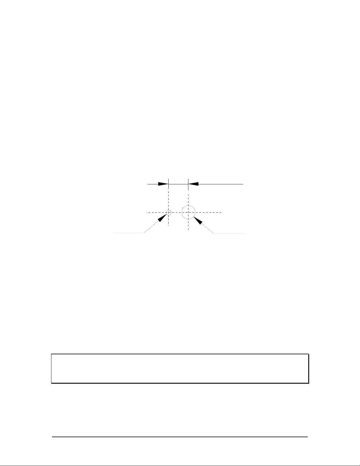
2.3 Equipment installation procedures
2.40”
1.68”
2 ea. 0.125
NOT TO SCALE
2 ea. 0.315
200-004-0004 Page 2-1 Rev. 4, Sept. 2000
Page 5
PS Engineering
PM2Crew Expansion module (11918)
For panel mounted installation
1. Using the template, drill four holes in the instrument panel in a location convenient to the pilot or
passengers position(s).
2. Insert the PM2CREW from behind the instrument panel, aligning the holes for the knobs.
3. Place the aluminum faceplate over the knob shafts and secure, using the two # 4-40 round head screws
provided.
4. Apply the PM2Crew label to the panel, using care to align the holes over the knob shafts.
5. Install the knobs over the volume and squelch control shafts.
Blind mounting:
1. Install the unit in a convenient bulkhead, as above. Add the aluminum doubler if the panel is less than
0.040” thick.
2. Remote mount the squelch control in a location convenient to the passengers.
3. If desired, the volume can be adjusted at installation, there are two holes in the side of the unit, one for
left, and another for right channel.
4. If desired, a remote switch (not included) can be installed to override the SoftMute function. This
should be located convenient to the passengers.
Remote Squelch Mounting:
0.472
Ø0.118
Ø0.323
Remote Squelch Mounting Holes
(Pot 675-020-0103)
Not to scale. Dimensions in inches,
2.4 Cable harness wiring
To complete the installation, a wire harness must be made as shown in Appendix D. PS Engineering can
make a custom-tailored wiring harness for the installer. All harnesses use Mil-spec quality components
with professional techniques, and are fully tested before shipment. Contact PS Engineering for more
information. The PM2Crew connects to the main unit through a 4- or 5-conductor, shielded cable.
2.4.1 Electrical Noise Issues
WARNING: You must use separate shielded cables for the microphone and headphone jacks. Combining
these two wires WILL cause loud oscillations and degrade the intercom function. The oscillation is caused
by the cross-coupling between the large headphone signal and the small microphone signal. The resulting
feedback is a high-pitched squeal that varies with the volume controls.
Shielding can protect the system from radiated noise (rotating beacon, power supplies, etc.). However,
installation combinations occur where minor interference is possible. The PM2CREW was designed in an
interference -protected chassis and has internal filter capacitors on all input lines.
200-004-0004 Page 2-2 Rev. 4, Sept. 2000
Page 6

PS Engineering
PM2Crew Expansion module (11918)
Ground loop noise occurs when there are two different return paths for the same signal, such as airframe
and ground return wire. Large cyclic loads such as strobes, inverters, etc., can inject audible signals onto
the airframe return path. Follow the wiring diagram very carefully to help insure a minimum of ground
loop potential. Radiated signals can be a factor when low level mic signals are bundled with current
carrying power wires. Keep these cables separated.
Insulating washers are required on all mic and headphone jacks to isolate them from aircraft ground.
2.4.2 Power Requirements
The PM2CREW was designed to work with the main intercom unit. No other power is required.
2.4.3 Interconnection with main unit
Interface between the PM2CREW and the main intercom is through a 5-wire shielded cable. Monaural
systems, such as the PM1000-series or PMA4000 require the left and right sides of the audio input be
combined. A 4-conductor cable can be used with these systems.
Function PM2CREW PM2000 PM1000 Series PMA4000
Expansion Power 1 17 15 17
Expansion Ground 14 1 2 3
Audio Input (rt.) 2 5
Audio Input (lt.)
Audio Output
15 18
3 4
16
3 5
4
2.4.4 Six and eight place units (11918P6 and 11918R6, 11918P8 and 11918R8)
The PM2CREW 6- and 8-place versions reconfigure the microphone input, converting mic grounds into
MIC high, and therefore are not interchangeable with a standard 4-place 11918 unit. Two extra headsets
are paralleled from the amplifiers.
2.4.5 Auxiliary Inputs
An entertainment device can be connected to the PM2CREW. Install a 1/8" music jack convenient to the
passengers to connect the stereo entertainment device into the system. A "Soft Mute" system is installed in
the PM2CREW that will mute the music during conversation on the local intercom. Radio traffic or
conversation on the main intercom will not
A second, monaural input is provided for other purposes, such as public address cabin briefing, or
providing radio interface for cases where the intercom does not have radio on the expansion bus
(PM1000D for example).
The PMA4000 music input is present on the expansion output. If this is used, DO NOT connect the
entertainment input to the PM2CREW.
A soft mute inhibit switch (not included) can be installed between 11918 connector pins 12 and 24.
Closing this switch places the PM2CREW into Karoake mode.
WARNING: Local oscillators and other internal signals from CD or radio equipment can cause undesired
interference with VHF navigation and communication equipment. Before takeoff, operate the
entertainment device to determine if there is any adverse effect on aircraft systems. If any unusual
operation is noted in flight, immediately switch the entertainment device off.
mute the music.
NOTE:
200-004-0004 Page 2-3 Rev. 4, Sept. 2000
Page 7

PS Engineering
PM2Crew Expansion module (11918)
Section III OPERATION
Switching on the intercom or PMA4000 automatically activates the PM2CREW unit. .
3.1 Adjusting The Volume
The volume control and squelch controls only affect the headsets connected to the PM2CREW directly,
and not the main unit.
3.2 Adjusting The Squelch Control
The PM2CREW provides individual VOX circuits for passenger 1, passenger 2, and another for
passengers’ three and four. With the engine running, set the squelch control knob by slowly rotating the
squelch control knob clockwise until you no longer hear the background noise in the earphones. When the
microphone is positioned properly near the lips, normal speech levels should open the channel. When you
have stopped talking, there is a delay of about one-second before the channel closes. This prevents squelch
closure between words, and helps eliminate choppy intercom conversation.
Section 4 Warranty and Service
4.1 Warranty
In order for the factory warranty to be valid, the installations in a certified aircraft must be accomplished by
a FAA- certified avionics shop and authorized PS Engineering dealer. If the unit is being installed by a
non-certified individual in an experimental aircraft, a factory-made harness must be used for the warranty
to be valid.
PS Engineering, Inc. warrants this product to be free from defect in material and workmanship for a period
of one year from the date of installation. During this one-year warranty period, PS Engineering, Inc., at its
option, will send a replacement unit at our expense if the unit should be determined to be defective after
consultation with a factory technician.
This warranty is not transferable. Any implied warranties expire at the expiration date of this warranty. PS
Engineering SHALL NOT BE LIABLE FOR INCIDENTAL OR CONSEQUENTIAL DAMAGES. This
warranty does not cover a defect that has resulted from improper or unreasonable use or maintenance as
determined by us. This warranty is void if there is any attempt to dissemble this product without factory
authorization. This warranty gives you specific legal rights, and you may also have other rights that may
vary from state to state. Some states do not allow the exclusion of limitation of incidental or consequential
damages, so the above limitation or exclusions may not apply to you.
4.2 Factory Service
The PM2CREW is covered by a one-year limited warranty. See warranty information.
Contact PS Engineering, Inc. at (865) 988-9800 or www.ps-engineering.com/support.shtml
return the unit. This will allow the service technician to provide any other suggestions for identifying the
problem and recommend possible solutions.
After discussing the problem with the technician and you obtain a Return Authorization Number, ship
using approved materials and carrier (no US Mail) product to:
PS Engineering, Inc.
Customer Service Department
9800 Martel Road
Lenoir City, TN 37772
(865) 988-9800 FAX (865) 988-6619
before you
200-004-0004 Page 4-4 Rev. 4, Sept. 2000
Page 8

PS Engineering
PM2Crew Expansion module (11918)
Appendix B Instructions for FAA Form 337
One method of airworthiness approval is through an FAA Form 337, Major Repair and Alteration (Airframe,
Powerplant, Propeller, or Appliance) In the case of the PM2CREW part number 11918, you may use the
following text as a guide.
Installed 4-place intercom expansion unit, PS Engineering PM2CREW, part number 11918 in (
location ) at station . Installed per AC43.13-2, Chapter 2, paragraph 23 (Instrument Panel
Mounting). Installed per PS Engineering Installation Operators Manual p/n 200-004-xxxx, revision 0,
dated ( ).
Interface to existing audio system in accordance with installation manual and in compliance with
practices listed in AC43.13-2, Chapter 2. All wires are Mil-Spec 22759 or 27500. No connection to the
aircraft dimmer bus is required. No additional connection to aircraft power is made.
Aircraft equipment list, weight and balance amended. Compass compensation checked. A copy of the
operation instructions, contained in PS Engineering document 200-004-( ), revision ( ), Dated ( ), is
placed in the aircraft records. All work accomplished listed on Work Order .
200-004-0004 Page A Rev. 4, Sept. 2000
Page 9

PS Engineering
p
n
h
PM2Crew Expansion module (11918)
Appendix D Wiring Information
PM2CREW (11918) Female Sub-D DB-25
Expansion Power In
Expansion Audio In (R)
Expansion Audio In (L)
Expansion Audio Output
Expansion Ground
NOTE
6
Music (L)
Music (R)
Pass 1 & 3 Phones (L) Hi
Pass 1 & 3 Phones (R) Hi
Headphone Lo
Pass 2 & 4 Phones (L) Hi
Pass 2 & 4 Phones (R) Hi
Headphone Lo
1
2
15
3
14
25
13
8
20
9
21
Mono Aux input 22
Pass 1 Mic Audio Hi
Pass 1 Mic Audio Lo164
Pass 2 Mic Audio Hi
Pass 2 Mic Audio Lo175
Pass 3 Mic Audio Hi
Pass 3 Mic Audio Lo186
Pass 4 Mic Audio Hi
Pass 4 Mic Audio Lo197
Expansion Power
Audio (right) from Main Unit
Audio (left) from Main Unit
Audio to Main Unit
Expansion Ground
Entertainment Input
(NOTE 6)
Mono Aux Input
(tape recorder, etc)
Pass 1 Mic
Pass 2 Mic
Pass 3 Mic
Pass 4 Mic
Pass #1
Pass # 3
1
2
3
4
5
6
PM2000
Series
17
5
PM1000
Series
15
16
PMA4000
Bottom Connector
17
4
18
4
1
3
2
5
3
See unit Installation manual
for complete information
Pass #2 Headphones
Pass # 4 Headphones
O
N
S
E
T
.
l
l
A
r
e
i
w
m
o
2
r
7
5
0
0
U
.
2
s
e
3
,
-
a
s
i
n
d
i
c
a
U
.
s
e
s
n
i
u
m
u
s
t
b
e
.
.
.
e
o
C
n
n
e
c
t
C
n
o
t
l
s
u
m
e
r
m
a
n
i
n
i
g
O
D
O
N
T
P
r
o
f
M
A
4
h
t
e
e
x
p
a
n
e
h
t
M
P
4
A
I
u
m
f
c
s
i
s
i
P
M
A
0
4
0
:
u
c
s
t
f
o
n
m
r
o
o
t
L
M
I
2
2
-
5
9
M
.
n
u
i
u
m
2
m
a
-
,
e
t
.
d
t
a
l
n
i
e
l
c
t
s
e
h
i
a
n
i
n
i
s
O
C
N
0
0
0
o
i
s
n
0
0
0
d
e
u
0
n
4
n
d
4
-
c
n
d
o
g
s
a
w
e
r
h
s
c
i
r
y
l
l
a
o
a
f
l
l
a
d
s
n
i
t
t
e
u
t
n
i
t
n
s
I
a
a
l
t
o
i
t
a
l
n
i
n
E
N
T
C
m
.
e
T
h
M
P
A
u
.
t
i
n
e
h
T
w
t
i
l
l
i
s
l
a
s
i
r
e
d
t
n
i
h
t
i
p
e
o
a
n
,
7
a
g
e
g
h
i
s
e
d
e
l
w
d
r
e
.
u
c
t
o
w
r
t
i
o
l
a
n
a
j
l
n
i
t
.
g
r
c
o
m
n
d
e
a
l
l
n
o
i
t
m
o
r
m
f
a
t
o
i
o
t
e
r
a
n
h
4
0
0
0
m
r
e
f
e
r
o
f
i
,
o
b
e
p
r
e
s
e
e
x
p
a
n
s
d
n
o
n
c
n
e
i
h
e
i
s
h
d
l
c
k
s
.
c
J
a
k
s
o
n
y
l
a
n
u
a
o
f
l
r
n
.
o
n
e
e
e
t
n
n
i
a
r
t
m
e
n
i
t
u
c
s
i
p
n
i
u
m
u
s
s
i
c
i
e
n
n
i
t
n
i
i
u
o
n
t
i
n
c
o
t
t
M
P
n
f
e
t
s
e
d
p
r
e
n
s
e
t
e
d
o
e
e
O
N
2
C
t
p
x
n
s
a
n
o
i
u
,
Y
L
a
e
l
t
v
e
R
W
E
.
Sq. Pot Outside Tab
Sq. Pot Center Tab
Sq. Pot Outside Tab
Inhibit Switch 1
Inhibit Switch 2
10
23
11
24
12
1
2
3
Remote Squelch
Soft Mute
Inhibit
(Switch not included)
Potentiometer
(11918R & 11918R6 only)
P/N 675-020-0103
9800 MARTEL ROAD, LENOIR CITY TN 37772
TITLE:
PM2CREW (11918) WIRING DIAGRAM
DOCUMENT NUMBER:
SIZE
DATE:
03/08/00
ECO
120-118-0000
REV
SHEET OF
1
1
1
PM2CREW (11918, 11918R) Wiring
200-004-0004 Page B Rev. 4, Sept. 2000
Page 10

PS Engineering
p
PM2Crew Expansion module (11918)
PM2CREW (11918P6) Female Sub-D DB-25
Expansion Power In
Expansion Audio In (R)
Expansion Audio In (L)
Expansion Audio Output
Expansion Ground
NOTE
6
Music (L)
Music (R)
Pass 1 & 3 Phones (L) Hi
Pass 1 & 3 Phones (R) Hi
Headphone Lo
Pass 2 & 4 Phones (L) Hi
Pass 2 & 4 Phones (R) Hi
Headphone Lo
1
2
15
3
14
25
13
8
20
9
21
Mono Aux input 22
Pass 1 Mic Audio Hi
16
Pass 1 Mic Audio Lo
Pass 2 Mic Audio Hi
17
Pass 2 Mic Audio Lo
Pass 3 Mic Audio Hi
Pass 3 Mic Audio Lo186
Pass 4 Mic Audio Hi
Pass 4 Mic Audio Lo197
Pass 5 Mic Audio Hi
4
Pass 5 Mic Audio Lo
Pass 6 Mic Audio Hi
5
Pass 6 Mic Audio Lo
Sq. Pot Outside Tab
Sq. Pot Center Tab
Sq. Pot Outside Tab
Inhibit Switch 1
Inhibit Switch 2
10
23
11
24
12
Expansion Power
Audio (right) from Main Unit
Audio (left) from Main Unit
Audio to Main Unit
Expansion Ground
Entertainment Input
(NOTE 6)
Mono Aux Input
(tape recorder, etc)
Pass 1 Mic
Pass 2 Mic
Pass 3 Mic
Pass 4 Mic
Pass 5 Mic
Pass 6 Mic
Soft Mute
Inhibit
(Switch not included)
Pass #1
Pass #3 Headphones
Pass # 2
Pass #4 Headphones
N
1
.
A
l
w
l
m
r
e
i
s
o
.
2
U
a
U
.
3
m
C
.
4
.
5
C
r
6
.
D
f
o
h
t
t
h
I
f
P
u
2
r
5
7
.
0
0
M
s
e
-
2
,
3
,
-
s
s
u
o
o
m
e
O
r
e
e
m
M
d
n
i
t
c
a
i
d
e
e
s
n
i
t
a
l
u
i
s
t
b
e
e
e
l
n
c
e
n
s
h
t
i
s
n
u
t
l
m
i
a
a
n
i
n
i
n
i
g
N
T
O
O
C
P
A
M
0
0
4
x
e
n
a
p
s
i
M
P
0
4
A
0
s
u
c
i
i
s
d
0
4
A
0
0
u
Remote Squelch
Potentiometer
(11918R & 11918R6 only)
PM2000
Series
17
5
PM1000
Series
15
16
18
4
1
3
2
See unit Installation manual
for complete information
Pass #5 Headphones
Pass #6 Headphones
T
O
:
S
E
t
c
o
f
n
o
m
r
t
o
M
-
L
2
I
7
2
9
n
i
m
u
m
u
4
2
d
n
a
-
4
c
d
n
o
.
g
n
c
r
t
d
l
e
n
u
s
t
N
.
0
o
n
0
e
s
i
n
u
s
a
w
r
e
h
s
c
a
i
y
l
l
l
a
f
o
t
s
a
i
t
t
n
r
e
c
i
n
t
s
n
I
t
l
a
a
t
l
l
t
a
l
n
o
i
f
n
i
E
N
T
C
m
o
e
h
T
M
P
A
u
.
t
i
n
e
h
T
r
w
t
i
i
l
a
l
s
o
l
r
e
i
n
d
i
t
h
e
p
o
,
n
e
n
a
9800 MARTEL ROAD, LENOIR CITY TN 37772
TITLE:
PM2CREW (11918P6) 6-place WIRING DIAGRAM
DOCUMENT NUMBER:
SIZE
120-118-0600
DATE:
03/08/00
ECO
g
a
c
t
n
o
g
n
i
o
t
a
i
o
r
e
r
4
0
f
e
e
b
e
d
g
e
s
w
r
o
l
a
l
j
.
m
n
e
o
n
m
m
a
t
i
t
n
a
h
0
0
m
o
,
e
r
p
e
r
x
n
a
p
c
o
n
n
SHEET OF
5
h
d
l
e
i
e
t
i
h
i
s
h
c
a
k
s
.
d
l
n
o
y
u
n
a
a
n
o
.
n
o
e
u
c
s
i
i
m
f
i
s
u
s
t
n
e
i
o
s
i
n
u
e
c
t
t
o
REV
1
PMA4000
Bottom Connector
d
r
e
i
w
d
l
e
c
J
a
k
s
f
l
r
o
e
t
n
e
r
u
p
n
f
t
i
c
s
i
p
n
i
e
n
t
i
n
O
N
M
P
C
2
1
1
17
4
5
3
.
i
a
t
e
m
n
t
n
n
i
e
s
d
e
e
r
n
s
e
t
d
e
t
e
x
R
o
a
p
s
i
n
n
o
L
u
,
Y
l
v
a
e
e
t
E
W
.
6-place PM2CREW (11918P6, 11918R6) Wiring
200-004-0004 Page C Rev. 4, Sept. 2000
Page 11

Sq. Pot Outside Tab
Sq. Pot Outside Tab
Sq. Pot Center Tab
Pass 4 Mic Audio Hi
Pass 4 Mic Audio Lo
Pass 7 Mic Audio Hi
Pass 7 Mic Audio Lo
Pass 8 Mic Audio Hi
Pass 8 Mic Audio Lo
PS Engineering
PM2Crew Expansion module (11918)
Pass 1 Mic Audio Hi
Pass 3 Mic Audio Hi
Pass Mic Audio Lo
Pass 2 Mic Audio Lo
Pass 6 Mic Audio Hi
Pass 6 Mic Audio Lo
Pass 2 Mic Audio Hi
Pass 1 Mic Audio Lo
Pass 5 Mic Audio Hi
Pass 5 Mic Audio Lo
Mono Aux input 22
Pass 1 & 3 Phones (R) Hi
Pass 2 & 4 Phones (L) Hi
Pass 2 & 4 Phones (R) Hi
Headphone Lo
Headphone Lo
Pass 1 & 3 Phones (L) Hi
Expansion Audio Output
Expansion Ground
Music (L)
Music (R)
PM2CREW (11918R8) Female Sub-D DB-25
Expansion Power In
Expansion Audio In (R)
Expansion Audio In (L)
10
11
23
Remote Squelch
Potentiometer
12
Pass 8 Mic
24
Pass 7 Mic
7
Pass 3 Mic
Pass 4 Mic
Inhibit Switch 2
Ring
17
5
Pass 2 Mic
Pass 6 Mic
Inhibit Switch 1
Tip
3.5 MM Stereo Plug
18
6
19
4
Pass 5 Mic
16
Pass 1 Mic
3
4
.
.
a
U
m
C
s
s
o
u
e
n
i
s
n
n
t
i
d
n
e
b
i
s
c
c
e
u
a
t
e
l
t
s
a
e
l
h
e
t
d
i
i
c
n
e
.
t
g
l
r
d
i
c
w
s
a
a
a
l
l
s
t
y
h
i
n
f
e
l
t
o
r
e
s
a
r
t
c
o
i
n
o
n
g
m
a
.
l
e
l
n
j
a
d
c
k
o
s
n
.
l
y
J
a
c
k
s
Mono Aux Input
(tape recorder, etc)
1
2
.
.
A
o
U
r
l
s
l
2
e
w
N
7
2
i
5
r
O
-
e
0
,
T
0
m
3
E
.
-
u
,
S
M
s
:
a
i
t
n
n
c
u
d
o
m
n
4
u
f
-
o
m
c
r
o
m
n
2
d
4
t
o
u
g
c
M
a
t
o
g
I
L
r
e
-
w
2
s
i
2
h
t
h
7
i
e
5
s
l
d
9
h
e
i
e
d
l
d
w
i
r
e
.
Pass # 4 Headphones
Pass #6 Headphones
9
21
Pass # 2
Pass #3 Headphones
Pass #5 Headphones
8
20
Pass #1
for complete information
14
25
13
Entertainment Input
1
See unit Installation manual
2
3
Expansion Ground
3
5
3
Expansion to main unit
Expansion Audio L
Expansion Audio R
5184
16
4
1215
Expansion Power
PM2000
17
PM1000
Series
15
PMA4000
Bottom Connector
17
Soft Mute
Inhibit
(Switch not included)
Pass #8 Headphones
Pass #7 Headphones
8-place PM2CREW (11918P8, 11918R8) Wiring
200-004-0004 Page D Rev. 4, Sept. 2000
 Loading...