

Page 1

Pilot Mic Audio Hi
Pilot Mic Audio Lo
Entertainment Input
Music (R)
9800 MARTEL ROAD, LENOIR CITY TN 37922
PM2000 (11915) WIRING DIAGRAM
SHEET OF
Jack Details:
Microphone
Ring (audio)
Barrel
(gnd)
(phone audio RT)
Barrel
(audio gnd)
Stereo Headphone
(phone audio LT)
RING
11-33 VDC
1A
To Aircraft Radio
Phone Audio Hi
TIP
To Aircraft Radio Mic Audio Lo
Aircraft Radio PTT
Aux Mic Jack
To Aircraft Radio
Phone Low
Ground
A/C HP Audio Hi
Pass 2 Mic
Pass 1 Mic
Copilot Mic
Copilot PTT
Exp. Audio Input
Exp. Power
Expansion Audio (R)
5 4 3 2 1
9 8 7 6
10
12 11
13
Connector when viewed from front
To A/C Radio Mic Audio Hi
Pilot Headphone Jack
Expansion Audio (L)
18 17 16 15 14
Pass 2 Audio (R)
Pass 2 Audio (L)
Pass 1 Audio R
Pass 1 Audio (L)
Copilot HP Audio (R)
Copilot HP Audio (L)
Pilot HP Audio (R)
Pilot HP Audio (L)
22 21 20 19
Pilot PTT
Pilot Mic
Misic Input (R)
Music Input (L)
24 23
A/C Radio PTT
A/C Mic Audio Hi
25
Power Input 11-33 VDC
1. All wire must conform to MIL-22759
or 27500. Minumum 24 gage shielded wire.
2. Use 2-, 3-, and 4-conductor with shield
as indicated.
3. Use insulating washers on all jacks. Jacks
must be electrically floating.
4. Connect shields at intercom end only
5. AUX headphone and microphone jacks are
required.
NOTES:
Copilot PTT
Copilot Mic Jack
Pilot Mic Jack
REV
DOCUMENT NUMBER:
TITLE:
SIZE
Pilot PTT
2
1
1
120-125-0002
8/27/98
DATE:
ECO
Stereo/Mono Switch
(required)
Passenger 1 Headphone
Copilot Headphone Jack
Passenger 2 Headphone
24
13114
12
25
22
16
21
8
20
9
7
19
6
15
2
3
10
23
11
Music (L)
Pilot Phones (L)
Pilot Phones (R)
A/C PTT
A/C Mic Audio Hi
A/C Mic Audio Lo
PM2000 Sub-D DB-25
Power In
Ground
A/C Radio Phone Audio Hi
A/C Radio Phone Audio Lo
PM2000 Operation/Installation Manual Page 8 Revision 2, August 1998
Pilot Phones Lo
Copilot Phone Audio (L)
Copilot Phone Audio (R)
Copilot Phone Audio Lo
Pass 1 Phone Audio (L)
Pass 1 Phone Audio (R)
Pass 1 Phone Audio Lo
Pass 2 Phones Audio (L)
Pass 2 Phones Audio (R)
Pass Phones Audio Lo
Pass 1 Mic Audio Hi
Pass 1 Mic Audio Lo
Pass 2 Mic Audio Hi
Pass 2 Mic Audio Lo
Copilot Mic PTT
Copilot Mic Audio Hi
Pilot Mic PTT
Mic Audio Lo
9800 Martel Road
Lenoir City, TN 37772
(423) 988-9800 FAX (423) 988-6619
PM2000
4-Place Stereo
Panel Mounted Intercom
Operator's and Installation Manual
NOTICE: In certified aircraft, warranty is
not valid unless this product is installed by an
Authorized PS Engineering dealer.
Revision 2, August 1998 Page 1 200-195-0002
Document Number 200-195-0002
Revision 2 August 1998
Page 2
Introduction
Congratulations on your purchase of a
PM2000 intercom! We at PS Engineering welcome you to our family.
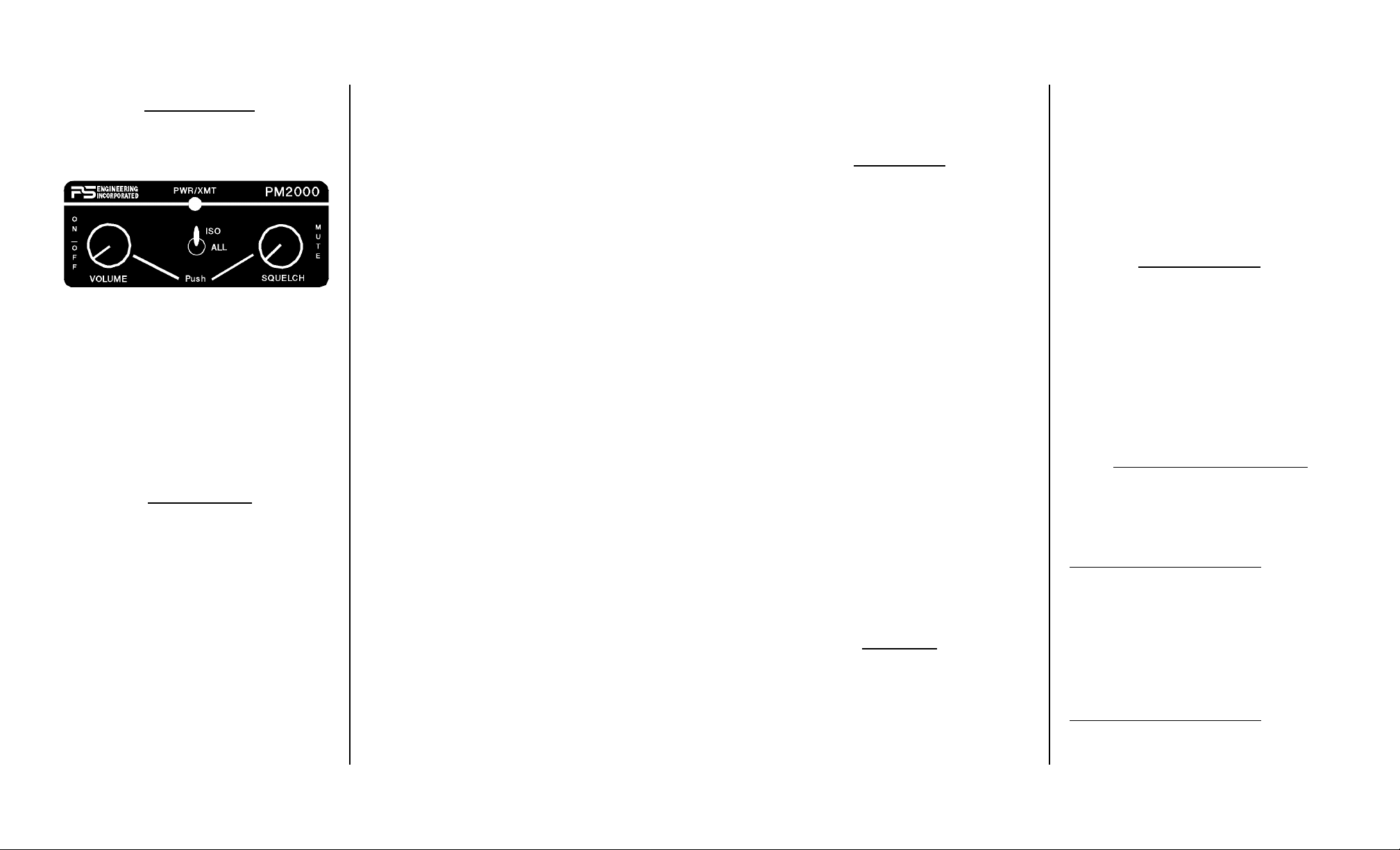
Front Panel of PM2000
The PM2000 is a panel mounted, 4-place
intercom that offers features that make this the
intercom of choice by pilots who demand quality sound. This manual provides information on
the installation and operation of the PM2000.
Please read it completely before installation to
reduce the risk of damage to the unit and maximize your enjoyment of its use.
Description
The PM2000 is a 4-place, STEREO, panel
mount intercom with individual volume and
VOX circuits for the pilot, copilot, and passengers 1 & 2.
Although there is only a single control
knob for the volume and squelch circuits, when
an adjustment is made to the volume control,
eight output amplifiers are being changed simultaneously. Likewise, when the squelch control knob is adjusted, three individual squelch
circuits are being changed at the same time.
A 2-position mode switch allows the pilot
to select one of two configurations. The "ALL"
mode places all headsets on a party line, hear-
ing intercom conversation and the aircraft radios.
In the "ISO" mode, the pilot is isolated from
all others and is connected to the aircraft radio
allowing un-interrupted radio communications.
The passengers continue to communicate with
themselves without distracting the pilot.
The PM2000 has an automatic fail-safe interconnect to the aircraft radio. If power is disrupted to the intercom for any reason, an internal
relay will connect the pilot's headset to the aircraft radio, permitting continued radio communications.
A 2-color LED glows green when power is
on and changes to red when someone presses
their Push To Talk.
Provision for an entertainment input allows
the pilot, copilot and passengers the option to
listen to music during flight. During intercom or
aircraft radio activity, this music automatically
mutes to permit easy communications. When the
activity ceases, the "Soft Mute™" circuit gradually returns the music to the original listening
volume. By depressing the mute control (located
on the VOX control) once, it is possible to have
the music remain at the unmuted level.
During various phases of flight, the degree
of importance of the aircraft radio will vary. Because the "ISO" mode directly connects the pilot
to the aircraft radio, select the "ISO" mode when
the pilot must have top priority on radio transmissions.
Both pilot and copilot have transmit capabilities. The PM2000 only allows the audio of
the person who presses their PTT to be transmitted over the aircraft radio. If both pilot and copilot press the PTT at the same time, the copilot
will override. Placing the unit in fail-safe
(turning off) will return control to the pilot position. When either pilot or co-pilot presses PTT,
may need several rotations before the adjustment is complete. When the aircraft radio becomes active, the music should mute.
Warranty
PS Engineering, Inc. warrants this product
to be free from defect in material and workmanship for a period of one year from the date of
installation. In certified aircraft, an FAA Form
337 must accompany the warranty card for this
warranty to be in effect. During the warranty
period, the unit must be returned to PS Engineering, Inc. and, at their option, it will send a
replacement at no charge.
This warranty is not transferable. Any implied warranties expire at the expiration date of
this warranty. WE SHALL NOT BE LIABLE
FOR INCIDENTAL OR CONSEQUENTIAL
DAMAGES. This warranty does not cover a
defect that has resulted from improper or unreasonable use or maintenance as determined by
us. This warranty is void if there is any attempt
to dissemble this product without factory
authorization.
This warranty gives you specific legal
rights, and you may also have other rights
which vary from state to state. Some states do
not allow the exclusion of limitation of incidental or consequential damages, so the above limitation or exclusions may not apply to your state.
Service
Call PS Engineering, Inc. at (423) 9889800 and ask for a technician. He may be able
to diagnose the problem and offer a solution
without the possible need for returning the unit.
If the unit does need servicing, ship product in
UPS approved packaging to:
PS Engineering, Inc.
Attn.: Service Department
9800 Martel Road
Lenoir City, TN 37772
(423) 988-9800
FAX (423) 988-6619
Appendix A
PTT Modifications
When received from the manufacturer, after-market PTT switches open the microphone
audio path to the "ring" connection of the PTT
mic plug. When the PTT is between the intercom and the headset, the intercom function will
not work until the PTT switch is depressed. A
simple modification can be performed to allow
proper intercom operation. NOTE: This modification does not alter normal operation.
Procedures For David Clark's PTT
1 Unscrew the round black plastic cover from the
jack.
2 Connect the joined black wires to the red wire.
3 Replace the round black plastic cover.
Procedures for the Telex's PT-200
1 Unscrew the round black plastic cover from the
jack.
2 Cut the red wire in the middle of the wire
3 Strip both ends of the insulation
4 Solder the two ends to the ground lug to the
PTT jack
5 Replace the round black plastic cover
Procedures for the Telex's PT-300
1 Unscrew the round black plastic cover from the
plug jack
PM2000 Operation/Installation Manual Page 2 Revision 2, August 1998
Revision 2, August 1998 Page 7 200-195-0002
Page 3

Adjusting The Volume
The volume control knob adjusts the loudness of the intercom and music for all headsets.
Turning the control clockwise increases the
audio. The PM2000 has two individual output
amplifiers for each headset in the system that
NOTE: In the event of a power failure to the
PM2000, or if the power switch is turned off, the
copilot will not hear the aircraft radio. Only the
pilot is connected to the aircraft radio.
provide plenty of undistorted audio output
power.
NOTE: Volume level does not change with
the number of headsets installed.
The volume control on the PM2000 does
not affect the volume level of the aircraft radio.
This gives the pilot ability to adjust the aircraft
radio and the ICS volume independently, adding flexibility to the system.
Adjusting The Squelch Control
This VOX operated intercom keeps all microphone channels off while the pilot, copilot or
passengers are not speaking. This reduces background noise from the aircraft. Only when
someone speaks will their microphones automatically turn on, passing the audio through the
system. Although there is just one squelch control, there are actually three distinct squelch
circuits. One each for the Pilot, Copilot, and
Passengers 1 & 2.
Set the Squelch control knob by slowly rotating the squelch knob clockwise until you no
longer hear the engine noise in the earphones.
When the microphone is positioned properly
near your lips, normal speech levels should
open the channel. When you stop talking, there
is a delay of about a half second before the channel closes. This prevents closure between words
and eliminates choppy communications.
Mode Select
The center switch is a 2- position mode
switch that allows the pilot to tailor the intercom
function to best meet the pilot's needs. Regardless of configuration, the pilot will always hear
the aircraft radio.
ISO (Up Position): The pilot is isolated from
the intercom and is connected to the aircraft radios only . He will hear only the aircraft radio
reception and sidetone (only during radio transmissions). Copilot and passengers will hear the
intercom and music but not the aircraft radio receptions or transmissions.
All (Middle position): All parties will hear
the aircraft radio reception and transmissions,
intercom, and music. However, during any intercom or radio communications, the music volume
automatically decreases. The music volume increases gradually back to the original level after
communications have been completed. There is a
lower switch position that is the same as ALL.
NOTE: When either the pilot or copilot PTT
is depressed, all microphones are off except for
the transmitting one.
Adjustment of Aircraft Radio Mute Level
The audio level that mutes the entertainment
when the radio is active is determined by the setting of the aircraft radio mute circuit. This circuit
is adjusted at the factory for optimum sensitivity.
If the entertainment appears to be always muted
(music stays at a constant low level even when
the ICS is not being used) the mute trigger level
must be adjusted. The mute level is changed by
adjusting the small potentiometer located at the
rear of the intercom. This is a 20-turn pot ,so you
all other mics are disabled. For pilot override,
the unit can be switched off.
Specifications
Input power: 12-28 Volts DC
Current Drain: < 150 mA Externally fused at 1
Amp
Headphone Impedance: 150-1000 ΩTypical
Audio Distortion: <10% @ 150mW into 150 Ω
load
Aircraft Radio Impedance: 1000 Ω Typical
±3 dB Mic Frequency Response: 350 Hz-6000 Hz
±3 dB Music Frequency Response: 200 Hz - 15
kHz
Net weight: 12 Ounces (.340 kg)
Dimensions: 1.25" H X 3.00" W X 5.50" D
(3.2 cm x 7.7 cm x 14 cm)
Installation
Note: Approval basis for installing a
PM2000 in certified aircraft is the
responsibility of the installer.
The PM2000 was carefully inspected mechanically and thoroughly tested electrically
before shipment. It should be free electrical or
cosmetic defects. Upon receipt, verify that the
parts kit contains the following:
A. Two # 4-40 Black machine screws
B. One reversible face plate
C. Two black knobs with white lines
D. One 25 pin Sub-D female connector
with hood
C. Two connector thumbscrews
D. One hole placement template
E. One stereo/mono switch for pilot head-
set.
F. Four complete sets of jacks with insu-
1.2 in
0.838 in
Ø0.125 in
Ø0.265 in
Ø0.25 in
Ø0.375 in
0.32 in
0.5 in
Hole placement diagram
lating washers and 1/8” music jack
1. Drill six holes as indicated in a location
convenient to the pilot position(s).
2. Once the holes have been drilled, insert
the PM2000 from behind the instrument panel
through the four holes for the knobs, LED, and
switch.
3. Place the aluminum face plate over the
knob shafts, and secure with the two black #4-40
screws provided.
NOTE: A custom wire harness can be cus-
tom made to your specifications by the
factory. Call the factory for more details.
4. Next install the two knobs by pressing
them on the shafts.
5. To complete the installation, a wire harness must be made and routed as depicted at the
back of the manual.
IMPORTANT: You must use separate
shielded cable for the microphone and headphone jacks. Combining these two wires WILL
cause loud oscillations and degrade the intercom
functions. The cause of the oscillation is due to
the fact that there is a much larger signal being
PM2000 Operation/Installation Manual Page 6 Revision 2, August 1998
Revision 2, August 1998 Page 3 200-195-0002
Page 4

carried by the headphone wire than the microphone wire. When these two wires are within the
same shielded cable, cross-coupling allows the
output to get back into the input, causing oscillations to occur.
If the aircraft already has pilot and copilot
headset jacks installed, you may re-use the hardware. Remove all wires from the copilot jacks
and discard them. NOTE: You may elect to use
the existing pilot headset jacks as the auxiliary
jacks.
NOTE: Auxiliary microphone and headset
jacks are required for a complete installation.
These provide troubleshooting and a back-up
access to the aircraft radios.
To hook the intercom into the system, simply parallel a set of mic and headphone wires
from this set of auxiliary jacks directly to appropriate points to the PM2000. Finally, install a
new set of pilot headset jacks and hook directly
to the appropriate points to the PM2000.
Electrical Noise Issues
Due to the variety of radio equipment found
in today's general aviation aircraft, there is the
potential for both radiated and conducted noise
interference. The PM2000 has a power supply
designed to reduce conducted electrical noise on
the power bus by over 50 dB. Although this is a
large amount of attenuation, it may not eliminate
all noise when the amount of noise is excessive.
In addition, there must be at least 13.8 Volts DC
present at the PM2000 for the power supply to
work in its designed regulation. Otherwise, it
will not be able to adequately attenuate all noise.
Shielding can prevent radiated noise (i.e.
beacon, electric gyros, switching power supplies)
however, installation combinations can occur
wherein minor interference is possible. The
PM2000 was designed in a RFI hardened chassis and has internal bypass capacitors on all
input lines. RFI can still cause problems, like
low or distorted sidetone, if correct shielding
techniques are not observed.
Ground loop noise occurs when there are
two ground paths for the same signal, i.e. airframe and ground return wire. Large cyclic
loads such as strobes, inverters, etc., can inject
audible signals onto the airframe. Follow the
wiring diagram very carefully to help insure a
minimum of ground loop potential. Radiated
signals can also be a factor when low level mic
signals are "bundled" with current carrying
power wires. Keep these cables separated as
much as possible.
Mil-spec 2– and 3-conductor shielded wire
MUST be used as shown in the installation diagram for proper operation.
It is very important that you use insulating
washers on all microphone and headphone
jacks to isolate the audio signal ground from
the aircraft ground.
Power Requirements
The PM2000 is designed to work with either 12 or 28 volt DC negative ground systems.
The PM2000 must be externally fused with a 1
ampere circuit breaker.
Side Tone
Note: Use the low level (or line) output from
any music device to connect to the PM2000.
Maximum input level is 1 V peak-to-peak.
DO NOT USE SPEAKER OUTPUT.
If the aircraft radio does not have sidetone
(the ability to hear your voice during radio
transmissions) the PM2000 can be modified to
provide sidetone for you. Call the factory for details.
Entertainment Hook Up
A stereo entertainment device (CD player,
cassette player, etc.) can be connected to the
PM2000. You may want to install a " stereo
connector (provided) somewhere in the panel so
that you can easily plug in an entertainment device.
The entertainment will be automatically
muted when the ICS or aircraft radio becomes
active. The “Soft Mute™” feature slowly returns
the music to full volume when the ICS or radio
becomes quiet. The muting feature is selectable
by depressing squelch control (PUSH-MUTE
switch).
External Push to Talk Installation
Part of the installation includes the installation of PTT (Push To Talk) switches that allow
the use of your aircraft communications radio for
transmissions.
There are three configurations that can be
used. You select the case that best fits your installation requirements.
NOTE: Only the person who presses their
PTT switch will be heard over the radio.
CASE I
PTT built into the pilot and copilot
yokes
Simply install the plugs from the headset into the aircraft headphone jacks. Use
the yoke mounted PTT to transmit. No
other action is required.
CASE II
Built-in PTT on the pilot side only,
but copilot transmit capabilities de-
sired.
This configuration requires a modified
external PTT plugged into the copilot's
mic jack. See Appendix A for modification details. When the copilot's PTT is
depressed, this activates an intercom relay that switches the mic audio input to
aircraft radio to the copilot.
CASE III
No built-in PTT switch at all
If there is no built-in PTT switch at
all, an external, properly modified PTT
switch is required. Both the pilot and
Front Panel Controls
copilot may use an external PTT. (See
Appendix A.)
OPERATING INSTRUCTIONS
With the installation complete, turn the
PM2000 on by pushing in the left knob
(volume control). This also engages the automatic fail-safe system.
PM2000 Operation/Installation Manual Page 4 Revision 2, August 1998
Revision 2, August 1998 Page 5 200-195-0002
 Loading...