

Page 1
Sound Quality. Sound Engineering.
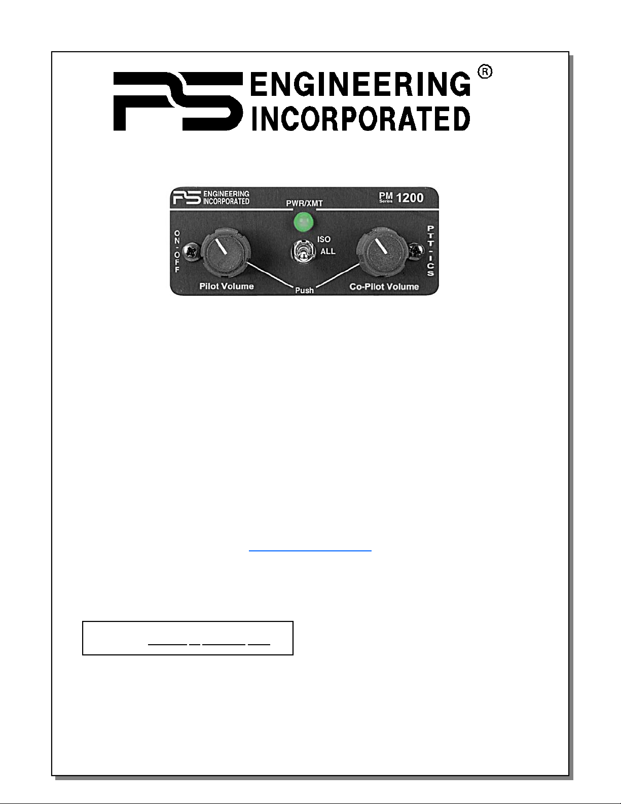
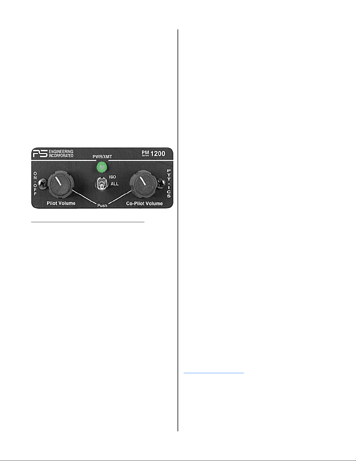
PM1200
Panel Mounted Intercom with
IntelliVOX®
for High Noise Application
Part No. 11960
Includes 11961 & 11960-Exp
Operator's and Installation Manual
PS ENGINEERING, INCORPORATED
9800 Martel Road
Lenoir City, TN 37772
Phone (865) 988-9800 FAX (865) 988-6619
www.ps-engineering.com
U. S. Patent 6,493,450
NOTICE: Warranty is not valid unless this product
is installed by an Authorized
Any reproduction or retransmittal of this publication, or any portion thereof, without the expressed written permission of PS Engi-
neering, Inc. is strictly prohibited. For further information contact the Publications Manager at PS Engineering, Inc.,
PS Engineering dealer.
PS Engineering, Inc. 2013©
Copyright Notice
9800 Martel Road, Lenoir City, TN 37772. Phone (865) 988-9800
Document Number 200-196-0104
Rev 12, March. 2013
200-196-0104 Page 1 March 2013 Rev. 12
Page 2
Section 1 General Information
1.1 Introduction
The PM1200 is a panel mounted, 2-place (expandable
with IntelliPAX p/n 11616R) monaural intercom system
(ICS) designed specifically for high-noise aircraft environments. Please read this manual completely before installation to minimize the risk of damage to the unit and to become familiar with all the features.
Both pilot and copilot have transmit capabilities over
the radio. The PM1200 allows only the person who presses
their radio PTT to be heard over the aircraft radio. If both
pilot and copilot press the PTT at the same time, the pilot
will have priority and override the copilot.
1.4 Approval Basis *None*
The PM1200, 11960, 11960-EXP, or 11961, is NOT
FAA Approved. It is the installers responsibility to determine suitability for installation.
1.2 Scope
This manual contains installation and operational in-
structions for the following PS Engineering units:
Part Number Description
11960 Push to talk intercom for use in noisy cockpits
11961 Same as above but remote (blind) mounting
11960-Exp Same as above, but with expansion capability
1.3 Description
The PM1200 is a 2-place (unless expanded), panelmounted intercom with PS Engineering‘s proprietary IntelliVOX® intercom protocol. The audio has been further enhanced with extra audio filtering for the microphones, and
added headphone audio power.
The PM1200 is backward compatible with PM1000II
units, P/N 11902, 11909 and 11922– contact factory for
details. However, the PM1000-series MUST be wired cor-
rectly per the manual, particularly the pilot radio PTT.
The unit can be used as either voice-activated, or push
to talk intercommunications, by simply pushing a front
panel switch.
The PM1200 has an automatic fail-safe interconnect to
the aircraft radio. If power to the intercom is disrupted, an
internal relay will connect the pilot's headset to the aircraft
radio. This allows continuous radio communications. Note:
The copilot will no longer hear aircraft radio when power is
removed.
An entertainment input is provided, allowing the users
to listen to music during flight. During intercom or aircraft
radio traffic, this music is automatically muted to allow
communications without distraction. When the activity
ceases, the Soft Mute™ circuit gradually returns the music
to the original volume.
1.5 Specifications
Input power: 13.8 - 27.5 Volts DC
Current Drain: < 250 mA (Externally fused at 1 Amp)
Output 120 mW into 150Ω @ 27.5 VDC
70 mW @ 13.75 VDC
Headphone Impedance: 150-1000 ohms typical
Aircraft Radio Impedance: 500- 1000 Ω typical
3 dB Music Frequency Response: 200 Hz to 15 kHz
Unit weight: 12 Ounces (0.342 kg)
Dimensions: 1.25" H x 3.00" W x 5.80" D
(3.2 x 7.6 x 14.7 cm)
Temperature -20ºC to +55ºC
Altitude 50,000 ft.
1.6
A. Headphones, 150-300Ω monaural, up to two as required
B. Microphones, up to two, as required
C. Crimping Tool, AMP 601966-1 , and Positioner, 601966-
D. Appropriately constructed interconnect wiring
E. Circuit Protection, 1 Amp.
F. Radio PTT switches (1-pilot, 1-copilot)
G. Intercom PTT switches (if desired) 2 ea.
Equipment required but not supplied
5 (or equiv.)
Section 2 Installation
2.1 General Information
The PM1200 comes with all necessary mechanical
hardware for installation. Installation of the PM1200, using
the appropriate wiring and hardware, does not require special tools or knowledge other than described in FAA Advisory Circular 43.13–2B. Installers should be qualified in
accordance with 14 CFR 65.81(b).
It is the installer's responsibility to determine the approval basis for this installation. An FAA From 337, or
other field approval may be required in a certified aircraft.
A custom-made wiring harness is available from PS Engineering, shipped within 5-business days of order. Visit
www.ps-engineering.com
2.2 Unpacking and inspection
The PM1200 was carefully inspected and thoroughly
tested before shipment. It should be free of electrical or cosmetic defect.
Upon receipt, verify that the parts kit includes:
for more information.
March 2013 Rev. 12 Page 2 200-196-0104
Page 3
(11960 & 11960-Exp) Installation Kit P/N 250-120-0100
Part Number Description Quantity
350-990-0015 Foam Mic Muff 2
350-9909-0001 Leather Mic cover 2
475-442-0002 #4-40 Machine screws, black 2
625-003-0001 Soft Touch knobs 2
425-025-0009 25 pin Sub-d connector shell 1
625-025-0001 Connector hood 1
425-020-5089 Crimp Pins (Male) 25
575-120-0001 Reversible aluminum face plate 1
250-000-0002 2-place jack kit 1
200-196-00XX Operator's and Installation Manual 1
122-102-0001 Drill Template 1
475-002-0002 Thumbscrews 2
PM1200 Remote (11961) Installation Kit P/N 250-120-0200
Part Number Description Quantity
350-990-0015 Foam Mic Muff 2
350-9909-0001 Leather Mic cover 2
425-025-0009 25 pin Sub-d connector sell 1
625-025-0001 Connector hood 1
425-0205089 Crimp Pins (Male) 25
250-000-0002 2-place jack kit 1
200-196-00XX Operator's and Installation Manual 1
675-120-0103 Pilot volume pot w/Switch ¼” shaft 1
675-020-0103 Copilot volume pot ¼” shaft 1
731-001-0001 Switch, SPDT On-On 2
625-020-0005 Knob, Black 1/2” shaft 2
475-002-0002 Thumbscrews 2
PM1200 Standard and Expansion
2.3 Equipment installation procedures
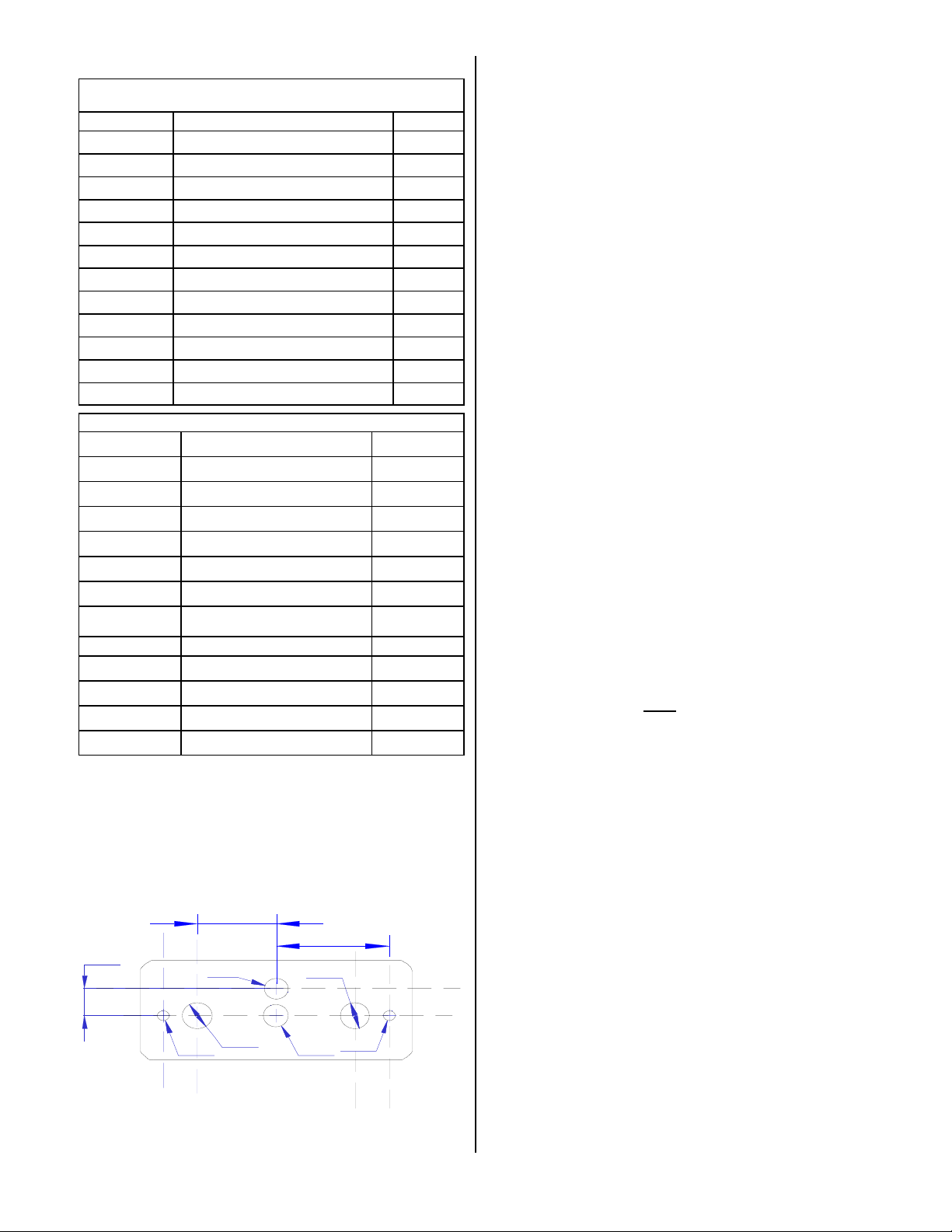
1.Using the template, drill six holes in the instrument panel
in a location convenient to the pilot position(s). The
intercom can be mounted horizontally or vertically with
supplied face plate.
2.Insert the PM1200 from behind the instrument panel,
aligning the holes for the knobs, LED, and switch.
0.840
1.200
0.320
PM1200 Hole spacing (Not to scale)
Ø0.25
Ø0.313
Ø0.125 Ø0.265
Dimensions in inches
Ø0.313
Ø0.125
3.Place the aluminum face-plate over the knob shafts and
secure, using the two # 4-40 round head screws provided.
4.Install the knobs over the volume and squelch control
shafts (except in the case of the 11961).
NOTE: See Page 9 for PM1200 Remote (11961R) installation diagram
2.2 Cable harness wiring
To complete the installation, a wire harness must be
made as shown in the appropriate diagram.
PS Engineering can make a custom-tailored wiring har-
ness for the installer. All harnesses use Mil-spec quality
components with professional techniques, and are fully
tested before shipment. Contact PS Engineering (865-988-
9800) for more information.
If the aircraft already has pilot and copilot headset jacks
installed, you may re-use them. Remove and discard all
wires from the copilot headset jacks. You may use the existing pilot headset jacks as the Auxiliary Aircraft Radio
Headset Jacks, but they should be moved to a new location
to avoid confusion with the pilot's headphone jacks. In the
event the intercom has to be removed for any reason, these
jacks provide access to the aircraft radio system.
To connect intercom into the aircraft audio system,
parallel the appropriate set of cables from the intercom to
the Auxiliary Aircraft Radio Headset Jacks. Finally, install
new headset jacks into the aircraft and connect them directly
to the appropriate pins of the PM1200. See the wiring diagram for all details of the wire harness interconnects.
2.2.1 Electrical Noise Issues
WARNING: You must use separate shielded cables
for the microphone and headphone jacks. Combining these
two wires WILL cause loud oscillations and degrade the
intercom function. The oscillation is caused by the crosscoupling between the large headphone signal and the small
microphone signal. The resulting feedback is a high-pitched
squeal that varies with the volume controls.
Due to the variety of the radio equipment found in to-
day's general aviation aircraft, there is the potential of both
radiated and conducted noise interference. The PM1200 has
a specially designed power supply to reduce conducted electrical noise on the power bus of the aircraft by at least 50dB.
Although this is a very large amount of attenuation, it does
not eliminate all noise when the amount is excessive. There
must be at least 12 Volts DC present at the PM1200 for the
power supply to work within its designed regulation. Otherwise, it will not be able to attenuate noise properly.
Shielding can protect the system from radiated noise
(rotating beacon, electric gyros, switching power supplies,
etc.). However, installation combinations can occur where
minor interference is possible. The PM1200 was designed
in an interference -protected chassis and has internal filter
capacitors on all input lines.
Ground loop noise occurs when there are two different
200-196-0104 Page 3 March 2013 Rev. 12
Page 4

return paths for the same signal, such as airframe and
ground return wire. Large cyclic loads such as strobes, inverters, etc., can inject audible signals onto the airframe
return path. Follow the wiring diagram very carefully to
help insure a minimum of ground loop potential. Radiated
signals can be a factor when low level mic signals are bundled with current carrying power wires. Keep these cables
separated.
Insulating washers are required
phone jacks to isolate them from aircraft ground. The use of
a conductor instead of a shield for ground return eliminates
these ground loop paths.
NOTE: Auxiliary microphone and headset jacks are
required for a complete installation. These aid in trouble-
shooting and a back-up access to the aircraft radios.
on all mic and head-
2.2.2 Power Requirements
The PM1200 was designed to work with either 12 or 28
volt DC negative ground systems. The PM1200 must be
externally protected with a one ampere (1A) circuit breaker
or fuse.
If any unusual operation is noted in flight, immediately
switch the entertainment device off.
If the PM1200 is used with an expansion unit, music
connected to the PM1200 will be heard in the panel unit and
expansion unit in ALL intercom mode. Music connected to
the expansion unit will only be heard by passengers in Crew
mode. Connect music source to BOTH units to distribute
the same music in both units.
2.2.5 Remote Configuration (11961)
The PM1200-Remote is designed for blind mounting.
The unit can be controlled through two remote potentiometers for volume and two SPDT switches. Mount the volume
controls in a location accessible to the pilot and copilot, and
the VOX and ISO switches convenient to the pilot in command position. The pilot’s volume pot also contains an onoff switch. See page 7 for wiring information.
NOTE: Due to the exposed signal paths for the volume con-
trols, these installations are more prone to electrical noise,
and extreme care must be taken in constructing the harness,
with wire runs as short as possible. PS Engineering does
not guarantee a noise-free installation in this configuration.
This version cannot be expanded.
2.2.3 PTT-ICS
The PM1200 is designed for noisy installations, such as
open cockpit aircraft. In addition to the Advanced Microphone Processing (AMP) and IntelliVOX® squelch, the unit
includes a VOX/PTT-ICS mode, controlled by the pushing
the copilot volume knob. In this mode, no pilot mic audio is
passed to the intercom unless pin 2 is connected to 16, or
copilot mic audio unless pin 15 is connected to pin 2
through a normally-open, momentary switch (not supplied).
2.2.4 Music Input
Entertainment devices can be connected to the
PM1200. Install a 1/8" jack convenient the pilot to connect
the entertainment device into the system. Since the PM1200
is monaural, you may want to connect the left and right
channels together at the music jack. Depending on the music source used, 10Ω resistors in series with the left and
right channels may be desireable to avoid loading and
possibly damaging the source.
Note: Use the low level (or line) output from any
music device to connect to the PM1200.
Maximum input level is 2 V peak-to-peak.
DO NOT USE SPEAKER OUTPUT.
These levels will cause internal damage.
A "Soft Mute" system is installed in the PM1200 that
will mute the music during intercom or radio activity.
WARNING: Local oscillators and other internal signals from CD or radio equipment can cause undesired interference with VHF navigation and communication equipment. Before takeoff, operate the entertainment device to
determine if there is any adverse effect on aircraft systems.
2.2.5 Expansion Configuration (11960-EXP)
The PM1200-EXP is configured internally to add expansion capability for more than two positions. Using an
IntelliPAX expansion unit, part number 11616, an additional 6 intercom positions can be available.
Although not marked, the lower position on the ISO/
ALL switch becomes a “Crew” position.
NOTE: The IntelliPAX includes IntelliVOX intercom, but is
not specifically designed for high noise environment. It may
be desirable to have an intercom P-T-T, by installing an inline, momentary normally open switch on the mic audio
lines, or use a portable intercom P-T-T that have an open
mic audio switch contact.
2.3 Post installation checkout
After wiring is complete, verify power is ONLY on pin
14 of the connector, and airframe ground on pin 1. Failure
to do so will cause internal damage and void PS Engineering's warranty.
1. Apply power to the aircraft and avionics.
2. Plug headsets into the pilot and copilot positions.
3. Verify that the pilot position can transmit and receive.
With the PM1200 in the OFF position (press the pilot’s volume control knob to turn off).
4. Turn the unit on and rotate the pilot volume clockwise,
about half way. Verify that the Pwr/Xmt light comes
on, and shows green. If the LED is red, stop testing
and trouble-shoot the microphone PTT installation.
5. Verify that the pilot can transmit and receive on the
com transceivers.
6. Verify that the LED in the intercom changes from
March 2013 Rev. 12 Page 4 200-196-0104
Page 5

green to red when a radio PTT is pressed.
7. Verify proper intercom operation for pilot and copilot.
For more information, consult Section 3.
8. Verify proper transmit and receive operation on the
copilot position, noting that the copilot PTT switch
allows proper transmission on the selected transceiver.
9. Verify proper Intercom system operation in the ALL and
ISO modes.
10. Verify that the intercom system does not adversely affect
any other aircraft system by systematically switching the
unit on and off, while monitoring the other avionics and
electrical equipment on the aircraft.
11. PTT ICS– Push the copilot volume control to activate the
PTT-ICS mode. Verify that the mic audio is heard when the
intercom push to talk switch is activated.
Section 3 OPERATION
3.1 On/Off and Volume
Press the left hand knob to turn the unit on and off.
This is also the fail-safe position. Whenever the unit is
off, or power removed, the pilot’s headset is connected
directly to the aircraft audio system.
The pilot's volume control knob adjusts the loudness of the intercom and music for the pilot's headset
only. It has no effect on aircraft radio volume level,
allowing an additional degree of aircraft radio listening flexibility. The copilot's volume control adjusts the
intercom volume for the copilot.
3.2 Squelch
The PM1200 incorporates PS Engineering’s revolutionary Advanced Microphone Processing (AMP)
and IntelliVox™ intercom squelch. No adjustment of
the squelch control is required. Through individual
signal processors, the ambient noise appearing in both
microphones is constantly being sampled. Non-voice
signals are blocked. When someone speaks, only their
microphone circuit opens, placing their voice on the
intercom.
The system is designed to block continuous tones,
therefore people humming or whistling in monotone
may be blocked after a few moments. The IntelliVox®
is designed to work with normal aircraft cabin noise
levels (70 dB and above). Therefore, it may not recog-
nize speech and clip syllables in a quiet cabin, such as
in the hangar, or without the engine running. This is
normal. For best performance, the headset microphone
must
be placed within ¼ inch of your lips, preferably
against them. It is also a good idea to keep the microphone out of a direct wind path. Moving your head
through a vent air stream may cause the IntelliVox™
to open momentarily. This is normal.
For optimum microphone performance, PS Engineering, Inc.
recommends installation of a Microphone Muff Kit (provided).
This will not only optimize VOX performance, but will improve
the clarity of all your communications
In some extremely high noise environments, it
may be desirable to have a push to talk (PTT) intercom, instead of relying on voice-activation (VOX). In
the PM1200 audio panel the PTT intercom capability
is added. To operate the PTT, push the PTT-ICS control switch on the copilot volume control. Using an
external ICS PTT switch for pilot and copilot will allow voice on the intercom.
3.3 Mode Select
The center switch is a mode control that allows the
pilot to tailor the intercom function to suit flight conditions. Regardless of configuration, the pilot will always hear the aircraft radio. NOTE: If there is a
power failure to the PM1200, or if the power switch is
turned off, the copilot will not hear the aircraft radio.
Only the pilot is connected directly to the aircraft radio.
ISO (Up Position): The pilot is isolated from the
intercom and is connected only to the aircraft radios.
He will hear the aircraft radio reception (and sidetone
during radio transmissions). Copilot and passengers
will hear themselves and music but not the aircraft
radio traffic.
ALL (Middle position): All parties will hear the
aircraft radio, intercom, and music. However, during
any ICS or radio communications, the music volume
automatically mutes. The music volume increases
gradually back to the original level after communications have been completed.
CREW (with expansion and 11960-EXP ONLY,
down position, unlabeled): Pilot and copilot have access to aircraft radios, and hear Music input to
PM1200. Passengers do not hear aircraft radio or pilot
and copilot, but can talk to each other, and hear Music
2. In non-expanded systems, the down and middle positions operate the same way.
The music input on the expansion unit will only be
active in Crew mode, otherwise, music from the
PM1200 EXP will be heard by passengers.
200-196-0104 Page 5 March 2013 Rev. 12
Page 6

Section 4
Warranty and Service
4.1 Warranty
In order for the factory warranty to be valid, the installations in aircraft must be accomplished by an FAA- certified avionics shop and authorized PS Engineering dealer. If
the unit is being installed by a non-certified individual a
factory-made harness must be used for the warranty to be
valid.
PS Engineering, Inc. warrants this product to be free
from defect in material and workmanship for a period of
one year from the date of sale. During this one year warranty period, PS Engineering, Inc., at its option, will send a
replacement unit to the PS Engineering dealer, if the unit
should be determined to be defective after consultation with
a factory technician. PS Engineering will not ship to the
end user under warranty, unless authorized by the dealer.
This warranty is not transferable. Any implied warranties expire at the expiration date of this warranty. PS Engineering SHALL NOT BE LIABLE FOR INCIDENTAL OR
CONSEQUENTIAL DAMAGES. This warranty does not
cover a defect that has resulted from improper or unreasonable use or maintenance as determined by us. This warranty
is void if there is any attempt to dissemble this product
without factory authorization. This warranty gives you specific legal rights, and you may also have other rights which
may vary from state to state. Some states do not allow the
exclusion of limitation of incidental or consequential damages, so the above limitation or exclusions may not apply to
you.
4.2 Factory Service
The PM1200 is covered by a one-year limited war-
ranty. See warranty information.
Call PS Engineering, Inc. at (865) 988-9800 before you
return the unit. This will allow the service technician to provide any other suggestions for identifying the problem and
recommend possible solutions.
After discussing the problem with the technician and
you obtain a Return Authorization Number, ship product
to:
PS Engineering, Inc.
Attn: Service Department
9800 Martel Road
Lenoir City, TN 37772
(865) 988-9800 FAX (865) 988-6619.
NOTE:
PS Engineering is not responsible for units shipped US
Mail.
If no method of payment is provided, the units will be returned COD. If no RMA or description of problem is present, the
shipment will be refused.
5.48
A
Ø0.136
PM1200 Remote P/N 11961
installation drawing (not to
scale)
4.0 3.50
AA
4.725
March 2013 Rev. 12 Page 6 200-196-0104
Page 7

PM1200, With EXPANSION Wiring P/N 11960-EXP Only
11960 Sub-D DB-25 Female on unit, Male on harness
Power In
Ground
A/C Radio Phone Audio Hi
A/C Radio Phone Audio Lo
Aircraft Radio PTT
Aircraft Mic Audio Hi
Aircraft Mic Audio Lo
Pilot Phone Audio Hi
Pilot Phone Audio Lo
Copilot Phones Hi
Copilot Phones Lo
Copilot Mic PTT
Copilot Mic Audio Hi
Mic Audio Lo
14
1
17
4
12
25
8
13
3
18
5
19
6
22
21
10
Note 7
Expansion Power
Expansion Out
Expansion In
Expansion Ground
1A
To Aircraft Radio
Phone Low
Pilot Phones
11-33 VDC
To Aircraft Radio
Phone Hi
AUX Headphone Jack
Aircraft Radio PTT
Aux Mic Jack
To Aircraft Radio Mic Audio Lo
To Aircraft Radio Mic Audio Hi
1
2
3
14
15
IntelliPAX
Expansion Unit
P/N 11616 or
11616R (remote)
Copilot Phones
Copilot PTT
Note 8
Copilot ICS PTT
PTT Common
Pilot ICS PTT
Pilot Mic PTT
Pilot Mic Audio Hi
Pilot Mic Audio Lo
Music Input Hi
Music Input Lo
1
l
A
l
.
w
r
i
m
e
o
2
.
U
T
O
N
:
S
E
3
.
U
4
.
C
A
5
.
U
6
.
7
.
M
E
w
O
R
8
.
u
2
r
7
5
0
0
M
.
s
e
2
a
-
n
d
s
e
n
i
s
u
a
l
t
o
n
n
e
s
c
t
h
X
h
U
e
a
d
p
T
I
N
U
M
S
u
s
i
c
c
o
n
n
x
p
a
n
s
o
i
n
b
l
l
i
p
e
r
e
s
n
m
e
u
c
s
i
a
d
o
i
a
n
I
d
15
2
16
24
23
11
20
7
s
t
c
o
n
o
f
o
t
m
r
L
-
I
M
2
2
7
5
n
i
u
u
m
m
2
4
g
3
-
c
o
n
i
g
w
e
d
i
l
s
h
o
n
e
E
B
T
e
c
e
t
d
w
h
e
n
e
n
t
i
s
o
u
r
P
C
S
a
n
d
u
c
o
r
t
w
a
s
h
e
r
s
o
n
n
i
a
t
e
r
t
c
o
a
n
d
c
i
m
r
M
C
O
P
A
T
o
t
h
P
e
t
n
i
"
A
L
L
"
p
n
a
s
s
e
n
g
c
e
c
a
b
n
e
T
s
T
c
t
h
w
i
9
g
e
s
h
e
i
l
d
e
w
d
r
i
e
h
t
i
s
h
e
i
l
a
l
l
a
j
c
k
e
m
n
o
d
o
p
h
o
n
e
A
B
L
E
W
1
M
2
0
w
0
o
m
d
M
e
.
e
r
h
e
a
d
c
o
n
n
e
c
e
s
N
O
T
.
d
a
s
n
i
d
c
i
a
e
d
t
s
.
n
y
l
a
j
c
k
s
a
T
I
E
H
i
a
p
l
p
l
u
s
c
c
i
s
e
o
n
t
e
d
t
o
t
s
u
p
p
l
.
r
e
r
e
q
u
r
i
e
d
X
P
e
a
r
o
n
l
n
y
i
B
O
e
i
d
.
.
A
N
O
N
S
I
N
P
/
,
1
1
9
6
0
-
E
n
i
n
e
c
e
d
t
o
e
x
t
p
"
r
C
T
H
i
,
a
e
w
o
m
d
"
e
e
l
f
a
n
d
t
f
X
n
s
o
i
n
.
g
i
h
t
r
c
h
a
n
Copilot ICS PTT
Pilot Mic Jack
Pilot PTT
Note 8
Music Jack
9800 MARTEL ROAD, LENOIR CITY TN 37772
TITLE:
PM1200 Expansion (11960E) WIRING
DOCUMENT NUMBER:SIZE
DATE:
P
n
e
l
120-196-0100
1/24/11
i
s
o
i
a
l
t
o
n
SHEET OF
s
i
c
o
n
s
d
i
1
e
r
e
d
Note 8
Pilot ICS PTT
REV
4
1
.
Note 8
200-196-0104 Page 7 March 2013 Rev. 12
Page 8

PM1200, REMOTE Wiring P/N 11961
PM1200R 11961 Sub-D DB-25 female unit, male on harness
To Aircraft Radio
A/C Radio Phone Audio Hi
A/C Radio Phone Audio Lo
Aircraft Radio PTT
Aircraft Mic Audio Hi
Aircraft Mic Audio Lo
Copilot Phones Hi
17
4
12
25
13
19
Copilot Phones Lo
Pilot Phone Audio Hi
18
Pilot Phone Audio Lo
ICS PTT Enable
ISO Mode
9
7
O
N
E
T
6
731-001-0001
Copilot Phones
Phone Hi
AUX Headphone Jack
To Aircraft Radio
Phone Low
Pilot Phones
T
O
N
E
7
731-001-0001
Aircraft Radio PTT
Aux Mic Jack
To Aircraft Radio Mic Audio Lo
To Aircraft Radio Mic Audio Hi
Copilot Mic PTT
Copilot Mic Audio Hi
Mic Audio Lo
Copilot ICS PTT
PTT Common
Pilot ICS PTT
Pilot Mic PTT
Pilot Mic Audio Hi
22
21
10
15
3
16
24
23
Pilot Mic Audio Lo
Music Input Hi
20
Music Input Lo
Remote_Intercom
Copilot_Remote_VOL
VOL Lo
Pilot_Remote_VOL
Aircraft Power
Aircraft Ground
11
6
8
5
14
1
Copilot Remote
Volume Control
675-020-0103
Copilot ICS PTT
Note 9
Music Jack
Pilot Remote
Volume Control
Power On/Off
675-120-0103
Pilot PTT
Note 9
1
.
A
l
l
w
i
2
7
o
r
2
.
s
U
e
2
3
.
U
s
e
i
4
.
C
o
n
n
5
.
A
U
X
6
.
A
p
p
l
y
i
n
P
i
l
o
7
.
A
p
p
l
h
e
8
.
T
P
9
.
P
T
T
s
1A
11-33 VDC
Copilot Mic Jack
Copilot PTT
Note 9
Pilot ICS PTT
Note 9
Pilot Mic Jack
T
O
N
E
r
e
m
5
0
0
.
a
n
-
n
s
u
l
a
e
c
t
s
h
e
a
d
i
n
g
g
t
I
o
s
y
i
n
g
/
N
1
i
w
t
c
S
u
s
o
n
f
t
c
m
o
r
M
i
n
u
m
u
m
d
c
3
-
o
n
d
u
c
t
i
n
a
g
w
s
h
e
h
i
e
l
a
t
d
s
i
n
p
h
o
n
e
a
n
d
o
u
n
r
d
t
o
P
l
a
t
e
m
o
d
e
.
o
u
g
r
n
d
t
o
P
1
9
6
1
c
a
n
n
h
o
e
s
n
o
o
t
p
r
9800 MARTEL ROAD, LENOIR CITY TN 37772
TITLE:
Remote PM1200 WIRING
DOCUMENT NUMBER:
SIZE
DATE:
3/15/13
ECO 1157
:
t
o
M
I
L
-
2
2
4
g
a
g
e
t
o
i
w
r
t
h
s
r
o
n
a
l
l
c
t
e
r
o
m
e
m
i
c
o
p
h
r
i
n
7
p
l
a
c
i
n
9
p
u
t
s
t
b
e
e
x
p
i
d
v
e
d
120-196-0300
SHEET 1 OF 1
2
7
5
9
s
h
i
e
l
d
e
d
w
i
e
.
h
s
j
a
n
o
e
s
u
a
r
i
e
l
d
i
n
a
s
d
i
c
a
t
e
d
.
s
k
c
d
o
n
l
y
n
e
j
a
c
s
k
n
t
h
e
i
t
e
n
i
t
i
n
t
o
n
d
e
d
b
e
REV
.
e
a
r
e
q
u
r
i
e
d
.
r
o
c
r
m
P
T
T
I
C
S
M
o
d
e
o
n
d
y
2
.
p
l
2
-
a
c
e
s
.
March 2013 Rev. 12 Page 8 200-196-0104
Page 9

PM1200, P/N 11960 Wiring
11960 Sub-D DB-25 Mating Connector is Male
Power In
Ground
A/C Radio Phone Audio Hi
A/C Radio Phone Audio Lo
Aircraft Radio PTT
Aircraft Mic Audio Hi
Aircraft Mic Audio Lo
Copilot Phones Hi
Copilot Phones Lo
Pilot Phone Audio Hi
Pilot Phone Audio Lo
14
1
17
4
12
25
13
19
6
18
5
1A
11-33 VDC
To Aircraft Radio
Phone Hi
AUX Headphone Jack
To Aircraft Radio
Phone Low
Copilot Phones
Pilot Headphone Jack
Aircraft Radio PTT
Aux Mic Jack
To Aircraft Radio Mic Audio Lo
To Aircraft Radio Mic Audio Hi
Copilot ICS PTT
PTT Common
Pilot ICS PTT
Copilot Mic PTT
Copilot Mic Audio Hi
Mic Audio Lo
Pilot Mic PTT
Pilot Mic Audio Hi
Pilot Mic Audio Lo
Music Input Hi
Music Input Lo
1
.
l
A
l
w
i
e
r
o
r
0
7
5
2
2
.
U
s
2
e
-
N
O
T
:
S
E
3
.
U
s
i
s
e
n
u
4
.
C
o
e
c
n
n
5
.
U
A
e
h
X
6
.
R
a
d
o
i
a
15
Copilot ICS PTT
Note 6
2
16
Pilot ICS PTT
Copilot Mic Jack
Note 6
22
21
10
24
Pilot Mic Jack
Copilot PTT
Note 6
23
11
Pilot PTT
Note 6
20
.
e
r
d
.
Music Jack
9800 MARTEL ROAD, LENOIR CITY TN 37772
TITLE:
PM1200 Standard (11960) WIRING
DOCUMENT NUMBER:SIZE
120-196-0100
DATE:
3/19/13 1 1
1157
ECO
REV
SHEET OF
1
7
s
u
m
0
a
t
a
n
n
t
o
c
m
r
f
o
t
o
I
L
M
-
7
5
2
2
9
.
M
n
m
i
i
2
m
u
4
a
g
s
e
g
l
h
e
d
i
e
w
d
.
i
e
r
d
n
o
c
-
3
d
u
n
a
l
t
i
n
w
g
a
h
s
l
s
e
d
i
a
p
d
n
h
e
o
I
d
C
T
P
S
r
t
c
o
w
t
h
i
h
e
s
i
a
d
l
n
s
i
d
t
e
a
c
i
d
h
s
e
s
o
r
n
l
a
l
k
j
c
a
.
s
t
n
i
c
r
t
e
e
m
o
o
d
n
l
n
y
n
d
a
i
m
c
h
o
r
p
e
o
n
k
c
a
j
s
a
e
r
q
e
r
u
i
T
w
s
i
t
h
c
s
n
e
o
t
u
s
i
l
p
e
p
d
200-196-0104 Page 9 March 2013 Rev. 12
 Loading...