

Page 1
May 2010 Page 1 200-124-0100PM1000II Specialty Intercom Manual Page 1 May 2010
PM1000II
Specialty Panel Mounted
Intercoms
Part No. 11906, 11908 (with Internal Recorder System)
Operator's and Installation Manual
PS ENGINEERING, INCORPORATED
9800 Martel Road
Lenoir City, TN 37772
Phone (865) 988-9800 FAX (865) 988-6619
www.ps-engineering.com
NOTICE: Warranty is not valid unless this product is
installed by an Authorized PS Engineering deale, or a
professionally made wiring harness is obtained from PS
Engineering or an authorized dealerr.
Document Number 200-124-0100
Rev. 3 May. 2010
Sound Quality. Sound Engineering.
Page 2

Section I General Information
1.1 Introduction
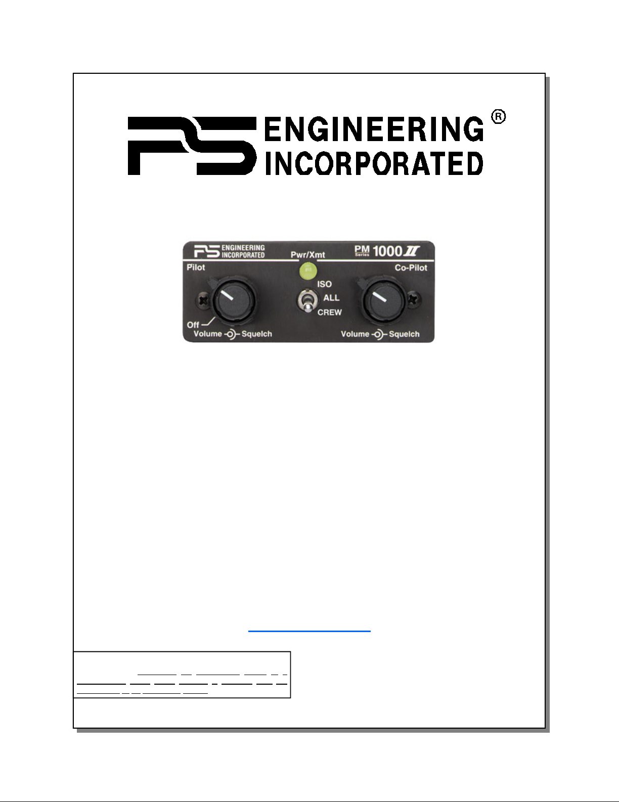
The PM1000II, is a panel mounted, 4-place
monaural intercom system (ICS). Please read this
manual completely before installation to minimize the
risk of damage to the unit and to become familiar with
all the features.
1.2 Scope
This manual contains installation and operational
instructions for the following PS Engineering units:
Part Number Description
11906 w/Pilot ISO and Internal Recorder System (IRS)
11908 Same as above w/internal crew function
1.3 Description
The PM1000II is a 4-place, panel mounted
intercom with individual volume and squelch controls
for the pilot and copilot. The copilot's squelch control
adjusts the trip level of the copilot and passengers.
A front panel mode switch allows the pilot to
select multiple intercom configurations:
"ISO" mode isolates the pilot from the intercom
and connects to the aircraft radio. The passengers can
continue to communicate with each other and listen to
entertainment without distracting the pilot. They do
not hear radio communications.
"ALL" mode places all headsets on a party line.
Each one hears aircraft radio, entertainment and can
use the intercom.
“CREW” (11908 only) allows the pilot and
copilot positions to hear the aircraft radios and use the
intercom, while the rear passengers can have their own
intercom conversation without disturbing the crew.
This also activates music 2 input.
The PM1000II has an automatic fail-safe
interconnect to the aircraft radio. If power to the
intercom is disrupted, an internal relay will connect the
pilot's headset to the aircraft radio. This allows
continuous radio communications. Note: The copilot
will no longer hear aircraft radio when power is
removed.
The 2-color LED shows green when power is on
and red during radio transmissions. This functions as a
stuck mic indicator.
An auxiliary input is provided, allowing the pilot,
copilot and passengers the option to listen to music
during flight. During intercom or aircraft radio activity,
this music is automatically muted to allow
communications without distraction. When the activity
ceases, the Soft Mute circuit will gradually return the
music to the original listening volume.
The "ISO" mode provides uninterrupted aircraft
radio communications for the Pilot. Because the pilot's
intercom volume control does not affect the aircraft
radio volume, it is possible to select various balances
of volume level between the ICS and the aircraft radio
while in the ALL mode. Reducing the intercom
volume, the pilot places the aircraft radio in the
foreground while the ICS is in the background.
Both pilot and copilot have transmit capabilities
over the radio. The PM1000II allows only the person
who presses their PTT to be heard over the aircraft
radio. If both pilot and copilot press the PTT at the
same time, the copilot will override (Ideally suited for
training environments). Pilot regains priority by
switching the unit off.
1.4 Approval Basis *None*
The PM1000II, part numbers 11906 and 11908
are NOT FAA Approved. It is the installer’s
responsibility to determine suitability for use.
1.5 Specifications
Input power: 13.8 - 27.5 Volts DC
Current Drain: < 250 mA (Externally fused at 1 Amp)
Headphone Impedance: 150-1000 ohms typical
Audio Distortion: <10% @ 75 mW into 150 load
Aircraft Radio Impedance: 1000 typical
3 dB Music Frequency Response: 200 Hz to 15 kHz
Unit weight: 12 Ounces (0.342 kg)
Dimensions: 1.25" H x 2.60" W x 5.50" D
(3.2 x 6.6 x 14 cm)
Temperature -20ºC to +55ºC
Altitude 50,000 ft.
PM1000II, p/n 11908, Front Panel
Page 3
May 2010 Page 3 200-124-0100PM1000II Specialty Intercom Manual Page 3 May 2010
1.6 Equipment required but not
supplied
A.Headphones, 150 monaural, up to four as
required
B.Microphones, up to four, as required
C.Interconnect wiring
D.Circuit Protection 1 Amp.
1.7 License Requirements
None
Section 2 Installation
2.1 General Information
The PM1000II comes with all necessary
hardware for installation.
Installation of the PM1000II, using hardware
supplied, and the wiring available separately from PS
Engineering or approved sources, does not require
special tools or knowledge other than described in
FAA Advisory Circular 43.13-2B. It is the installer's
responsibility to determine the approval basis for this
installation.
2.2 Unpacking and inspection
The PM1000II was carefully inspected
mechanically and thoroughly tested electronically
before shipment. It should be free of electrical or
cosmetic defect.
Upon receipt, verify that the parts kit includes
the following:
2.3 Equipment installation procedures
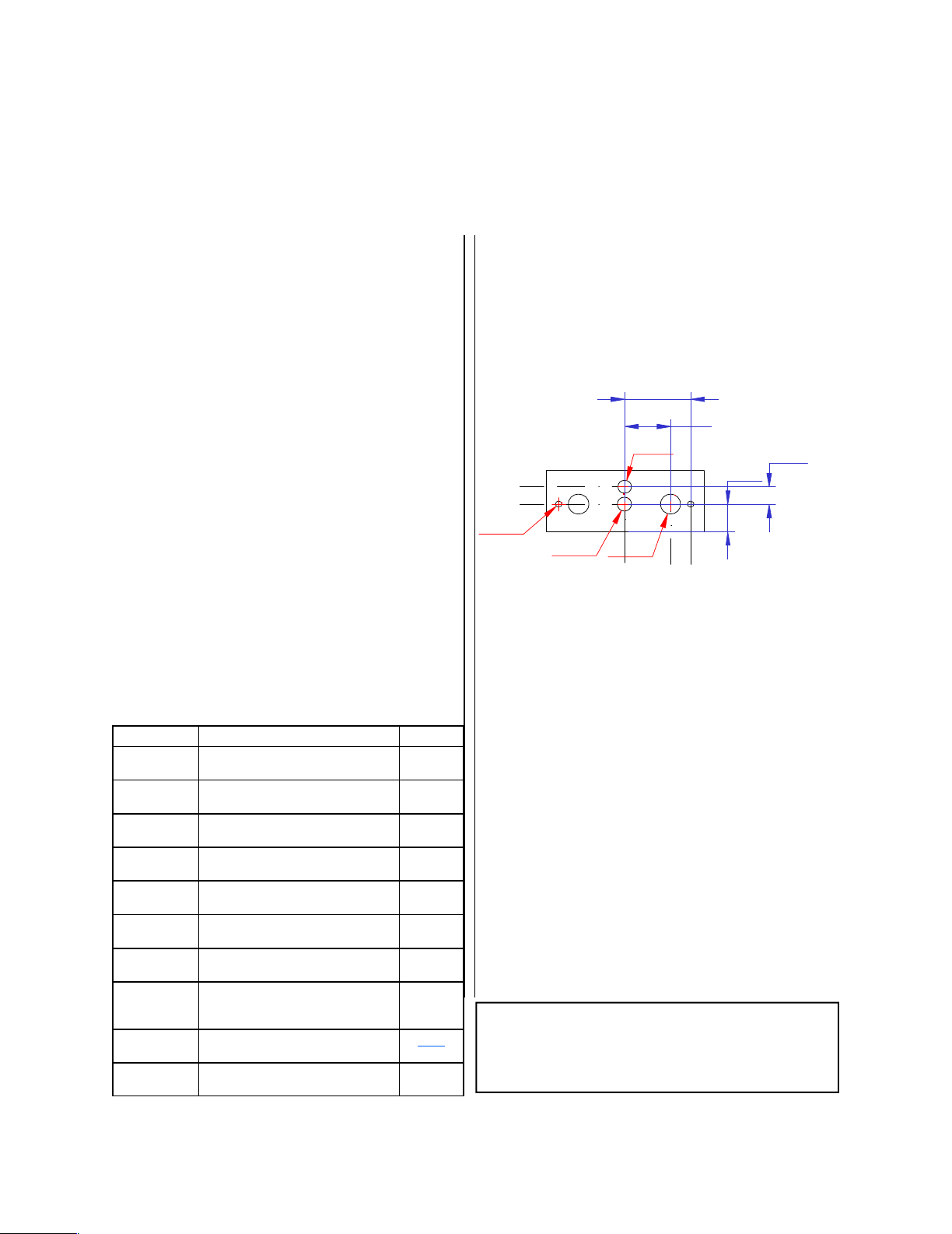
1.Using the template, drill six holes in the instrument
panel in a location convenient to the pilot position
(s).
2.Insert the PM1000II from behind the instrument
panel, aligning the holes for the knobs, LED, and
switch.
3.Place the aluminum face-plate over the knob shafts
and secure, using the two # 4-40 round head screws
provided.
4.Install the knobs over the volume and squelch control
shafts.
2.2 Cable harness wiring
To complete the installation, a wire harness must be
made as shown in Appendix D.
PS Engineering can make a custom-tailored wiring
harness for the installer. All harnesses use Mil-spec
quality components with professional techniques, and
are fully tested before shipment. Contact PS Engineering
for more information.
If the aircraft already has pilot and copilot headset
jacks installed, you may re-use them. Remove and
discard all wires from the copilot headset jacks. You
may use the existing pilot headset jacks as the Auxiliary
Aircraft Radio Headset Jacks, but they should be moved
to a new location to avoid confusion with the pilot's
headphone jacks. In the event the intercom has to be
removed for any reason, these jacks provide access to
the aircraft radio system.
NOTE: Auxiliary microphone and headset jacks
are required for a complete installation. These
provide troubleshooting and a back-up access to the
aircraft radios.
Part Number Description Quantity
475-442-0002 #4-40 Machine screws, black 2
625-002-0001 Concentric inner knobs 2
625-002-0002 Outer knobs w pointer 2
425-025-0095 25 pin Sub-d Shell 1
625-025-0001 Connector hood 1
575-002-0004
575-002-0002
Reversible aluminum face plate
Reversible face plate w/crew
11906
11908
11910 4-place mono jack kit (incl. phones and
mic jack, insulating washers and 1/8”
music jack)
1
200-124-0100 Operator's and Installation Manual WEB
122-102-0001 Drill Template 1
425-020-5089 Male Pins—Crimp 25
PM1000II Hole spacing (Not to scale)
Ø0.125 in
Ø0.265 in
Ø0.375 in
Ø0.25 in
0.838 in
1.2 in
0.5 in
0.32 in
Page 4

To connect intercom into the aircraft audio system,
parallel the appropriate set of cables from the intercom
to the Auxiliary Aircraft Radio Headset Jacks. Finally,
install new headset jacks into the aircraft and connect
them directly to the appropriate pins of the PM1000II.
See the wiring diagram for all details of the wire
harness interconnects.
2.2.1 Electrical Noise Issues
WARNING: You must use separate shielded
cables for the microphone and headphone jacks.
Combining these two wires WILL cause loud
oscillations and degrade the intercom function. The
oscillation is caused by the cross-coupling between the
large headphone signal and the small microphone
signal. The resulting feedback is a high-pitched squeal
that varies with the volume controls.
Due to the variety of the radio equipment found in
today's general aviation aircraft, there is the potential of
both radiated and conducted noise interference. The
PM1000II has a specially designed power supply to
reduce conducted electrical noise on the power bus of
the aircraft by at least 50dB. Although this is a very
large amount of attenuation, it does not eliminate all
noise when the amount is excessive. There must be at
least 12 Volts DC present at the PM1000II for the
power supply to work within its designed regulation.
Otherwise, it will not be able to attenuate noise
properly.
Shielding can protect the system from radiated
noise (rotating beacon, electric gyros, switching power
supplies, etc.). However, installation combinations can
occur where minor interference is possible. The
PM1000II was designed in an interference -protected
chassis and has internal filter capacitors on all input
lines.
Ground loop noise occurs when there are two
different return paths for the same signal, such as
airframe and ground return wire. Large cyclic loads
such as strobes, inverters, etc., can inject audible
signals onto the airframe return path. Follow the wiring
diagram very carefully to help insure a minimum of
ground loop potential. Radiated signals can be a factor
when low level mic signals are bundled with current
carrying power wires. Keep these cables separated.
Insulating washers are required on all mic and
headphone jacks to isolate them from aircraft ground.
The use of a conductor instead of a shield for ground
return eliminates these ground loop paths.
2.2.2 Power Requirements
The PM1000II was designed to work with either
12 or 28 volt DC negative ground systems. The
PM1000II must be externally protected with a one
ampere (1A) circuit breaker or fuse.
2.2.4 IRS Playback wiring
PM1000II part number 11906 and 11908 have an
internal recorder that stores recent incoming radio
messages. A 3.5 mm jack is provided on the rear of the
intercom unit to interface this function. Install a
momentary, normally open (NO), switch in a location
convenient to the pilot, and wire to the 3.5 mm plug
(included) across the tip and sleeve contacts. Closing
this switch will activate the playback. A low-current
rated switch is recommended.
2.2.3 Entertainment Input
Entertainment devices can be connected to the
PM1000II. Install the 1/8" jack convenient the pilot to
connect the entertainment device into the system. A
"Soft Mute" system is installed in the PM1000II that
will mute the music during intercom or radio activity.
Since the PM1000II is mono, and music jack is
stereo, it may be desirable to combine left and right
input channels at the jack, for connection to the music
input. Some devices may require a 10 Ώ resistor in
series with the left and right channels to isolate the
output amplifiers
The PM1000II w/Crew, 11908 has two (2)
entertainment inputs. In the ALL or ISO modes, Music
#1 is heard by everyone (except by the pilot in ISO
mode). In the CREW mode, pilot and copilot will hear
Music #1 while the passengers will hear entertainment
#2.
WARNING: Local oscillators and other internal
signals from CD or radio equipment can cause
undesired interference with VHF navigation and
communication equipment. Before takeoff, operate the
entertainment device to determine if there is any
adverse effect on aircraft systems. If any unusual
operation is noted in flight, immediately switch the
entertainment device off.
2.3 Post installation checkout
After wiring is complete, verify power is ONLY
Note: Use the low level (or line) output from any music device to connect to
the PM1000II. Maximum input level is 2 V peak-to-peak.
DO NOT USE SPEAKER OUTPUT.
These levels will cause internal damage.
Page 5

May 2010 Page 5 200-124-0100PM1000II Specialty Intercom Manual Page 5 May 2010
on pin 14 of the connector, and airframe ground on pin
1. Failure to do so will cause internal damage and
void the warranty.
1. Apply power to the aircraft and avionics.
2. Plug headsets into the pilot, copilot and
passenger positions.
3. Verify that the pilot can transmit and receive
with the PM1000II in the OFF position (pilot
volume knob fully counterclockwise).
4. Rotate the pilot volume clockwise, about half
way. Verify that the Pwr/Xmt light comes on,
and shows green. If the LED is red, stop testing
and trouble-shoot the microphone PTT
installation.
5. Verify that the pilot can transmit and receive on
the com transceivers.
6. Verify that the LED in the intercom changes
from green to red when a microphone is keyed.
7. Verify proper intercom operation for pilot,
copilot and passengers. For more information,
consult Section III.
8. Verify proper transmit and receive operation on
the copilot position, noting that the copilot PTT
switch allows proper transmission on the selected
transceiver.
9. Verify Intercom operation in the ALL, ISO and
CREW (if equipped) modes.
10.Verify that the intercom system does not
adversely affect any other aircraft system by
systematically switching the unit on and off,
while monitoring the other avionics and
electrical equipment on the aircraft.
11.Recorder Check Out Tune a communications
radio to an active 2-way channel, (not AWOS or
ATIS). Listen for a radio transmission. When it
is concluded, press the “Playback” button and
verify that the last message plays in the pilot
headset.
Section III OPERATION
With the installation complete, turn the PM1000II
on by rotating pilot's volume control. This also
engages the automatic fail-safe system. The pilot's
volume control does not control the volume of the
aircraft radio, allowing an additional degree of aircraft
radio listening flexibility.
3.1 Adjusting the Volume
The pilot's volume control knob adjusts the
loudness of the intercom and music for the pilot's
headset only. It has no effect on aircraft radio volume
level. The copilot's volume control adjusts the volume
for the copilot and passengers (11906).
In the 11908 (crew) units, the volume level for
both passengers can be adjusted by a screwdriver
adjusted potentiometer located on the left hand side of
the intercom as viewed from the front. It is possible to
adjust the overall output volume to the passenger
headsets by changing this potentiometer. Rotating the
potentiometer counterclockwise increases the
passenger volume.
3.2 Squelch Control
The PM1000II provides individual VOX circuits
for the pilot and copilot. The ability to adjust the trip
level of these VOX circuits (squelch control) allows
the use of dissimilar headsets without the frustration of
clipping the first syllables. The PM1000II has three
squelch circuits, one for the pilot, copilot, and one for
the passengers. With individual VOX circuits,
background noise is dramatically reduced.
With the engine running, set the squelch control
knob by slowly rotating the squelch control knob
clockwise until you no longer hear the background
noise in the earphones. When the microphone is
positioned properly near the lips, normal speech levels
should open the channel. When you have stopped
talking, there is a delay of about one second before the
PM1000II, p/n 11906
PM1000II with crew, p/n 11908
Page 6

be recording, increase the aircraft radio volume.
Warranty and Service
4.1 Warranty
In order for the factory warranty to be valid, the
installations in a certified aircraft must be accomplished by
an FAA- certified avionics shop and authorized PS
Engineering dealer. If the unit is being installed by a noncertified individual in an experimental aircraft, a factorymade harness must be used for the warranty to be valid.
PS Engineering, Inc. warrants this product to be free
from defect in material and workmanship for a period of one
year from the date of purchase from an authorized PS Engineering Dealer. During this one year warranty period, PS
Engineering, Inc., at its option, will send a replacement unit
at our expense if the unit should be determined to be
defective after consultation with a factory technician. The
customer is responsible for return shipment costs.
This warranty is not transferable. Any implied
warranties expire at the expiration date of this warranty. PS
Engineering SHALL NOT BE LIABLE FOR INCIDENTAL
OR CONSEQUENTIAL DAMAGES. This warranty does
not cover a defect that has resulted from improper or
unreasonable use or maintenance as determined by us. This
warranty is void if there is any attempt to dissemble this
product without factory authorization. This warranty gives
you specific legal rights, and you may also have other rights
which may vary from state to state. Some states do not allow
the exclusion of limitation of incidental or consequential
damages, so the above limitation or exclusions may not
apply to you.
4.2 Factory Service
The PM1000II is covered by a one-year limited
warranty. See warranty information.
Call PS Engineering, Inc. at (865) 988-9800 before you
return the unit. This will allow the technician to provide any
other suggestions for identifying the problem and
recommend possible solutions.
After discussing the problem with the technician and
you obtain the required Return Authorization Number,
ship product to:
PS Engineering, Inc.
Attn: Service Department
9800 Martel Road
Lenoir City, TN 37772
(865) 988-9800 FAX (865) 988-6619.
NOTE:
PS Engineering is not responsible for units shipped
US Mail.
If no method of payment is provided, the units will be
returned COD. If no RMA or description of problem is
present, the shipment will be refused.
channel closes. This prevents squelch closure between
words, and helps eliminates choppy intercom
conversations.
3.3 Intercom Mode Select
The center switch is a three position mode control
that allows the pilot to tailor the intercom function to
suit flight conditions. Regardless of configuration, the
pilot will always hear the aircraft radio. NOTE: If
there is a power failure to the PM1000II, or if the
power switch is turned off, the copilot will not hear the
aircraft radio. Only the pilot is connected directly to
the aircraft radio.
ISO (Up Position): The pilot is isolated from the
intercom and is connected only to the aircraft radios.
He will hear the aircraft radio reception (and sidetone
during radio transmissions). Copilot and passengers
will hear themselves and music but not the aircraft
radio traffic.
ALL (Middle position): All parties will hear the
aircraft radio, intercom, and music. However, during
any ICS or radio communications, the music volume
automatically mutes. The music volume increases
gradually back to the original level after
communications have been completed.
CREW (Down Position) (ONLY version with
crew, part number 11908 ): Pilot and copilot are
connected on one intercom channel while the
passengers are on a separate and independent channel.
The pilot and copilot are connected to the aircraft radio
and may listen to Music #1. Passengers can continue to
communicate with themselves without disturbing the
pilot and copilot and may listen to Music #2.
3.4 Internal Recorder System (IRS)
This records the last radio messages, storing up to
60 seconds of received radio phrases. Only the pilot
will hear the playback. The last message received will
be the first one played back. This function is intended
to help the pilot determine is a radio call was meant for
him, and not to store clearance or ATIS.
To play back the last recorded message, press the
switch labeled “Playback” installed in the aircraft. To
cancel the playback, press and hold the playback button for two seconds. The next time the button is
pressed, the earlier message will be heard. If the radio
becomes active while a message is playing, the message playback will stop. The new audio will not be
stored. Press play to restart the message you were
playing.
A radio signal of more than 1 VRMS is needed to
trigger the IRS. Therefore, if the IRS does not seem to
Page 7

May 2010 Page 7 200-124-0100PM1000II Specialty Intercom Manual Page 7 May 2010
1A
11-33 VDC
14
1
11906 Sub-D DB-25-- Unit has female (socket)
To Aircraft Radio
Phone Hi
17
4
Power In
Ground
A/C Radio Phone Audio Hi
A/C Radio Phone Audio Lo
18
5
Pilot Phone Audio Hi
Pilot Phone Audio Lo
Copilot
Phones
Passenger 1
Phones
Passenger 2
Phones
Copilot, Pax 1 & 2 Phones Hi
Copilot, Pax 1 & 2 Phones Lo
19
6
20
7
9
Music Jack
Pass 1 Mic
Pass 2 Mic
22
21
10
Music Input Hi
Music Input Lo
Pass 1 Mic Audio Hi
Pass 1 Mic Audio Lo
Copilot Mic PTT
Copilot Mic Audio Hi
Mic Audio Lo
Copilot PTT
Pilot Mic PTT
Pilot Mic Audio Hi
Pilot Mic Audio Lo
AUX Mic Jack
Pilot PTT
To A/C Radio Mic Audio Hi
Aircraft Radio PTT
12
25
13
15
3
16
2
Expansion Power
Expansion Audio In
Expansion Audio Out
Ground
To Pin 1 of 11918 expansion module
To Pin 3 of 11918
To Pin 2 and 15 of 11918
To Pin 14 of 11918
24
23
11
8
Pass 2 Mic Audio Hi
Pass 2 Mic Audio Lo
To Aircraft Radio
Phone Low
AUX Headphone Jack
To Aircraft Radio Mic Audio Lo
Pilot Headphone Jack
These pins used for expansion modules only
NOTES:
1. All wire must conform to MIL-22759
or 27500. Minumum 24 gage shielded wire.
2. Use 2-, 3-, and 4-conductor with shield
as indicated.
3. Use insulating washers on all jacks.
4. Connect shields at intercom end only
5. AUX headphone and microphone jacks are
required.
Copilot Mic Jack
Pilot Mic Jack
Aircraft Radio PTT
Aircraft Mic Audio Hi
Aircraft Mic Audio Lo
TITLE:
PM1000II (11906) WIRING DIAGRAM
9800 MARTEL ROAD, LENOIR CITY TN 37772
For use with p/n 11906 and
IntelliPAX expansion
module only
PM1000II NO crew, p/n 11906
IRS Playback Schematic (Section 2.2.4)
Page 8

IRS Playback Schematic (Section 2.2.4)
1A
11-33 VDC
14
1
11920 Sub-D DB-25 Female (Sockets) on unit
To Aircraft Radio
Phone Hi
17
4
Power In
Ground
A/C Radio Phone Audio Hi
A/C Radio Phone Audio Lo
18
5
Pilot Phone Audio Hi
Pilot Phone Audio Lo
Passenger 1
Phones
Passenger 2
Phones
Copilot Phones Hi
Copilot Phones Lo
19
6
20
7
9
Music Jack 1
Pass 1 Mic
Pass 2 Mic
22
21
10
Music Input 1 Hi
Music Input 1 Lo
Pass 1 Mic Audio Hi
Pass 1 Mic Audio Lo
Copilot Mic PTT
Copilot Mic Audio Hi
Mic Audio Lo
Copilot PTT
Pilot Mic PTT
Pilot Mic Audio Hi
Pilot Mic Audio Lo
Aux Mic Jack
Pilot PTT
To A/C Radio Mic Audio Hi
Aircraft Radio PTT
12
25
13
24
23
11
8
Pass 2 Mic Audio Hi
Pass 2 Mic Audio Lo
To Aircraft Radio
Phone Low
AUX Headphone Jack
To Aircraft Radio Mic Audio Lo
Pilot Headphone Jack
Copilot Mic Jack
Pilot Mic
Jack
Aircraft Radio PTT
Aircraft Mic Audio Hi
Aircraft Mic Audio Lo
16
3
Music Jack 2
Music Input 2 Hi
Music Input 2 Lo
15
2
Pass 1 & 2 Phones Hi
Pass 1& 2 Phones Lo
Copilot Headphone Jack
no connection
no connection
TITLE:
9800 MARTEL ROAD, LENOIR CITY TN 37922
NOTES:
1. All wire must conform to
MIL-22759 or 27500.
Minumum 24 gage shielded wire.
2. Use 2-, 3-, and 4-conductor
with shield as indicated.
3. Use insulating washers
on all jacks.
4. Connect shields
at intercom end only
5. AUX headphone and
microphone jacks required.
PM1000II (11908) with CREW and IRS
PM1000II With Crew p/n 11908
Page 9

May 2010 Page 9 200-124-0100PM1000II Specialty Intercom Manual Page 9 May 2010
PS Engineering, Inc. 2010©
Copyright Notice
Any reproduction or retransmittal of this publication, or any portion thereof, without the expressed written permission of PS Engineering,
Inc. is strictly prohibited. For further information contact the Publications Manager at PS Engineering, Inc., 9800 Martel Road, Lenoir City,
TN 37772. Phone (865) 988-9800
PM1000II Part Number 11906________ or 11908_________
Serial Number______________________________________
Purchase Date_______________________________________
Installed by:_________________________________________
12345
1415161718
6789
19202122
10
2324
1112
25
13
Pass 1 & 2 Phones Hi
Pass. 1& 2 Phones Lo
Power (11-33 VDC)
Ground
Music 2 Input Hi
Music 2 Input Lo
A/C Radio Ground
A/C Radio Input
Pilot Phones Gnd
Pilot Phones Hi
Copilot & Pass Phones Lo
Copilot & Pass Phones Hi
Music Input Lo
Music Input Hi
Pass 2 Mic Hi
Copilot Mic Hi
Pass 1 Mic Hi
Copilot PTT
Copilot & Pass Mic Lo
Pilot Mic Audio Hi
Pilot Mic Lo
Pilot PTT
A/C Radio PTT
A/C Mic Audio Hi
A/C Radio Gnd
11908 Connector layout, viewed from rear
12345
1415161718
6789
19202122
10
2324
1112
25
13
No Connect
No Connect
Power (11-33 VDC)
Ground
No Connect
No Connect
A/C Radio Ground
A/C Radio Input
Pilot Phones Gnd
Pilot Phones Hi
Copilot & Pass Phones Lo
Copilot & Pass Phones Hi
Music Input Lo
Music Input Hi
Pass 2 Mic Hi
Copilot Mic Hi
Pass 1 Mic Hi
Copilot PTT
Copilot & Pass Mic Lo
Pilot Mic Audio Hi
Pilot Mic Lo
Pilot PTT
A/C Radio PTT
A/C Mic Audio Hi
A/C Radio Gnd
11906 Connector layout, viewed from rear
 Loading...