

Page 1
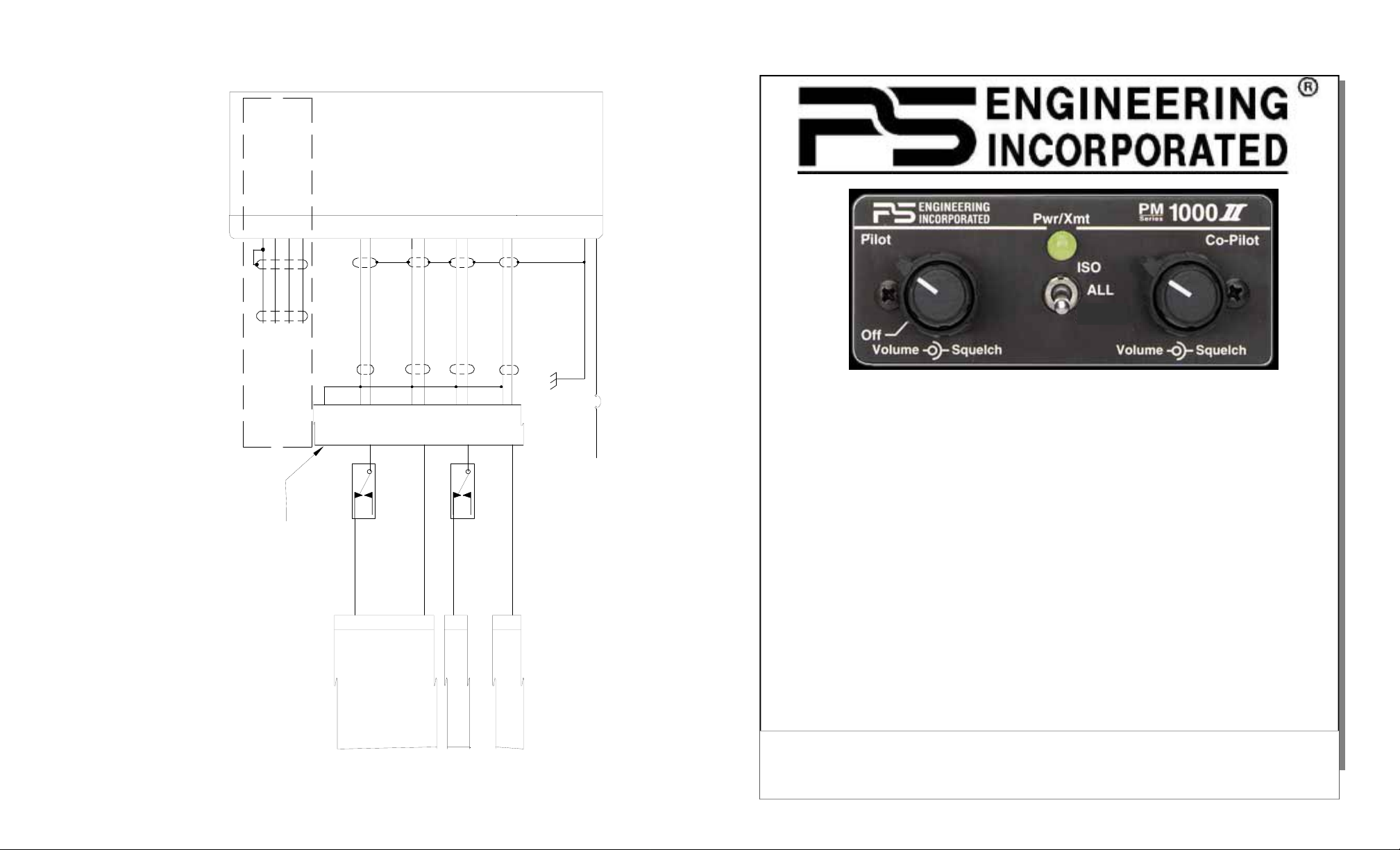
PM1000-DAP Wiring, Collins
N
O
T
E
S
8
7
6
5
4
.
.
.
T
P
P
C
h
o
L
o
i
w
3
s
n
3
e
t
c
a
r
P
o
c
a
n
i
t
n
n
f
t
i
s
d
h
g
e
u
a
g
r
r
r
f
a
e
a
o
t
c
u
i
p
o
t
n
r
o
n
e
d
r
v
y
i
s
m
i
o
f
f
o
a
u
o
r
y
s
r
l
i
y
n
2
b
f
-
e
u
o
p
n
r
p
l
a
m
u
i
c
c
s
a
k
e
e
t
e
s
i
d
o
d
o
n
p
u
n
i
o
n
p
l
y
n
s
.
a
.
e
t
x
P
p
L
a
3
n
3
d
i
i
n
f
g
w
i
t
r
h
e
i
s
s
i
s
z
y
e
s
t
p
e
e
m
r
m
.
i
t
s
.
3
.
.
.
a
o
U
A
T
s
r
s
l
h
2
l
e
i
i
n
w
7
s
2
d
5
i
d
-
r
i
0
c
,
e
i
a
a
0
3
m
g
t
.
-
e
,
r
M
u
a
d
a
s
m
.
i
n
n
t
d
i
c
m
i
s
o
4
u
n
b
-
m
c
f
a
o
o
s
r
n
2
m
e
d
4
d
u
t
g
o
o
c
a
n
t
M
o
g
B
r
e
I
L
w
e
s
-
e
i
2
h
t
c
h
2
i
e
h
7
s
l
c
d
5
h
r
e
9
a
i
e
d
f
t
l
d
w
d
i
i
a
r
e
g
.
r
a
m
"
A
u
d
i
o
S
y
s
t
e
m
,
C
O
L
L
I
N
S
,
3
5
6
C
-
4
&
3
6
5
F
-
3
#
K
4
0
1
6
4
2
.
"
:
2
1
.
.
C
F
I
t
B
N
h
O
A
B
T
e
U
R
4
E
a
T
2
R
U
i
r
2
I
O
C
p
S
.
l
O
N
E
a
I
n
t
:
M
W
e
i
T
s
S
h
I
t
i
T
o
n
i
Y
s
H
t
d
S
e
w
e
D
n
T
i
t
d
r
E
U
e
i
e
n
r
M
A
m
d
g
L
M
i
s
d
n
A
o
i
e
U
a
l
U
e
g
S
t
h
l
D
r
y
T
a
a
I
m
O
a
t
B
s
t
E
h
S
w
a
e
Y
O
a
g
s
S
s
R
u
y
T
d
i
D
s
d
E
r
t
a
E
e
e
M
w
.
m
R
Y
n
E
w
o
D
f
u
o
i
l
l
r
S
m
b
K
P
e
u
i
E
n
s
c
g
C
t
o
c
I
A
m
F
h
i
I
p
e
r
C
a
c
2
A
k
t
0
i
b
L
0
w
l
L
,
e
i
Y
r
S
.
i
n
e
g
r
i
a
d
l
i
a
g
r
a
m
s
s
u
p
p
l
i
e
d
w
i
t
h
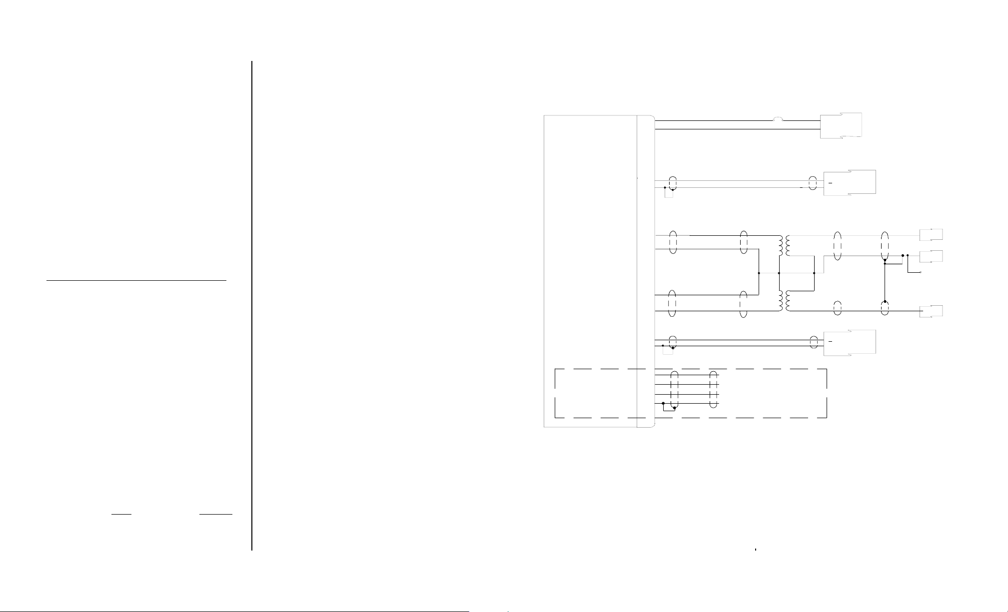
Collins Audio System
King Air 200
Power Out (+9VDC)
Expansion Audio In
Expansion Audio Out
Ground
15
3
16
2
These pins used for
expansion modules only
E
TIE TO EXISTING AUDIO LO
(TO AUDIO GROUND PLUG)
Copilot Phones Hi
Copilot Phones Lo
19
6
H
COPILOT SPK/PH SWITCH
UNUSED SECTION
SPKR
PHONE
Pilot Phone Audio Hi
Pilot Phone Audio Lo
Copilot Mic Audio Hi
Mic Audio Lo
18
5
21
10
F
D
PHONE
Pilot Mic Audio Lo
11
PILOT SPK/PH SWITCH
UNUSED SECTION
SPKR
Pilot Mic Audio Hi
23
PL 33 (previously unused pins)
C
11900D Sub-D DB-25 Male
Power In
Ground
14
1
Power Ground
Ground at GND plug See Note
1A
11-33 VDC
PM1000-DAP
Panel Mounted Intercom
for Dual Audio Panel Aircr aft
Part No. 11900D
41 PLT Mic to intph Amp
5 COPLT UNMUTED AUDIO IN
PLUG A PLUG B
8 COPLT MIC TO INTPH AMP
K1-NC
6 PLT UNMUTED AUDIO IN
K4-NC
PLUG APLUG A
REF: 108-340467-9
Audio PC Board
PM1000-DAP Dual Audio System Intercom Page 12 April 2008
FAA-TSO C50c
Operator's and Installation Manual
PS ENGINEERING, INCORPORATED
Phone (865) 988-9800 FAX (865) 988-6619
200-191-0000 Revision 5 April 2008
Any reproduction or retransmittal of this publication, or any portion thereof, without the expressed written permission of PS Engineering,
Inc. is strictly prohibited. For further information contact the Publications Manager at PS Engineering, Inc., 9800 Martel Road, Lenoir
Revision 5 Page 1 200-191-0000
9800 Martel Road
Lenoir City, TN 37772
www.ps-engineering.com
PS Engineering, Inc. 2007©
Copyright Notice
City, TN 37772. Phone (865) 988-9800
Page 2
Section I General Information
1.1 Introduction
The PM1000-DAP, is a panel mounted, 2place intercom system (ICS) designed for installation in aircraft with existing dual audio control
panels (ACP). Please read this manual completely before installation to minimize the risk
of damage to the unit and to become familiar
with all the features.
1.2 Scope
This manual contains installation and operational instructions for the following PS Engineering unit:
Part Number Description
11900D w/Pilot ISO for Dual ACP Installation
1.3 Description
The PM1000-DAP is a 2-place, panel
mounted intercom with individual volume and
squelch controls for the pilot and copilot. This
unit is specifically designed to provide voiceactivated intercom in a dual audio control panel
aircraft.
A front panel mode switch allows the pilot
to select multiple intercom configurations:
"ISO" mode isolates the pilots from the
intercom and connects to the aircraft radio. This
mode defeats the intercom capability. The copilot retains all radio functions.
"ALL" mode places all headsets on a party
line. Each pilot hears their selected aircraft radio, entertainment and can use the intercom.
“CREW” (only
expansion unit ) allows the pilot and copilot
positions to hear the aircraft radios and use the
intercom, while the rear passengers can have
if equipped with optional
their own intercom conversation without disturbing the crew.
The LED shows green when power is on, and
is not a transmit indicator. The PM1000-DAP
does not have a direct interconnection with the
aircraft audio, and therefore will not affect operation if power is removed.
Because the crew’s intercom volume control
does not affect the aircraft radio volume, it is possible to select various balances of volume level
between the ICS and the aircraft radio while in
the ALL mode. Reducing the intercom volume,
the pilots can place the aircraft radio in the foreground while the ICS is in the background.
1.4 Approval Basis FAA-TSO
The PM1000-DAP, part is FAA Approved
under TSO-C50c. It is the installer’s responsibility to determine approval basis (Part 91, 121, Part
135, etc.) and suitability for use.
1.5 Specifications
Input power: 13.8 - 27.5 Volts DC
Current Drain: < 250 mA (Externally fused at 1 Amp)
Audio Distortion: <10% @ 70 mW into 150 Ω load
3 dB mic Frequency Response: 300 Hz to 6.0 kHz
Unit weight: 12 Ounces (0.34 kg)
Dimensions: 1.25" H x 2.60" W x 5.50" D
(3.2 x 6.6 x 14 cm)
Temperature -20º C to +55º C
Altitude 15,000 ft.
1.6 Equipment required but not
supplied
A. Interconnect wiring
B. Existing Dual Audio Control Panel System
C. Circuit Protection, 1 Amp.
D. Headsets
N
1.7 License Requirements
None
King Air 200 w/ dB Systems
11900D Sub-D DB-25 Male
Power In
Ground
Pilot Mic Audio Hi
Pilot Mic Audio Lo
Pilot Phone Audio Hi
Pilot Phone Audio Lo
Copilot Phones Lo
Copilot Phones Hi
Copilot Mic Audio Hi
Mic Audio Lo
Power Out (+9VDC)
Expansion Audio In
Expansion Audio Out
Ground
1
.
T
I
N
C
R
E
S
M
O
S
E
T
O
R
O
F
S
:
2
U
.
A
C
9
B
B
t
h
e
3
.
T
h
i
s
4
.
A
l
l
w
5
e
.
s
U
6
.
L
P
3
3
7
.
P
o
w
8
.
T
h
i
s
o
C
n
Y
E
S
U
W
I
T
T
7
a
2
e
c
t
H
N
I
O
:
T
i
s
h
3
i
r
d
i
r
P
r
o
a
w
.
I
t
i
s
i
n
t
e
p
n
l
a
e
t
o
d
i
a
g
r
a
m
i
s
c
e
m
u
s
t
c
n
o
,
3
-
,
a
n
d
4
i
n
s
a
r
e
p
r
n
a
d
g
u
r
o
n
n
f
i
g
u
r
a
t
i
o
n
t
c
t
h
e
f
a
c
t
o
14
1
11-33 VDC
Power Ground
23
11
18
5
6
19
21
10
15
3
16
These pins used for expansion
unit only
2
T
E
U
M
M
B
T
S
R
O
A
U
D
i
r
g
i
n
d
n
e
d
e
t
e
r
m
r
e
a
t
f
o
r
m
-
n
c
o
d
e
v
i
o
u
d
a
m
i
s
f
o
r
y
f
o
E
L
A
U
I
O
D
d
i
a
g
r
a
m
l
s
e
o
l
y
s
a
i
n
e
t
h
a
t
t
h
d
e
f
r
o
B
m
e
t
o
M
I
L
-
2
2
u
c
r
t
o
i
t
w
h
s
u
l
y
n
e
u
s
y
b
e
p
i
c
k
e
r
2
l
a
-
p
c
e
s
r
i
n
f
o
r
m
t
a
E
E
R
D
S
D
P
I
I
F
C
S
T
Y
S
E
w
a
d
s
r
a
g
u
i
d
e
s
t
y
s
h
e
c
c
r
a
7
5
9
s
h
i
e
l
d
d
p
i
.
n
s
d
u
p
a
o
l
n
.
y
n
i
o
o
n
E
M
a
n
w
f
o
r
K
i
n
g
i
r
.
e
Y
e
m
f
t
d
o
r
2
a
s
t
P
e
x
p
A
u
o
t
u
m
c
s
h
e
i
l
l
w
b
e
c
o
m
i
a
7
i
n
L
3
a
n
p
g
r
a
"
m
A
u
d
5
0
0
.
i
n
M
i
m
d
a
i
t
c
e
d
.
3
i
f
i
r
w
e
s
i
i
n
d
g
t
h
i
s
s
1A
L
A
L
C
Y
2
0
0
,
e
S
r
i
a
c
k
i
r
w
i
n
g
d
a
t
i
b
l
e
.
i
o
S
y
s
m
t
e
u
2
m
4
g
a
z
e
p
e
r
i
t
m
s
y
s
t
e
m
.
DD
EE
a
Copilot Mic Gnd
a
Pilot Mic Gnd
l
i
a
g
r
s
a
m
s
u
p
p
l
i
e
d
i
w
,
u
l
D
a
s
t
y
e
S
,
m
4
1
#
g
e
h
i
s
e
l
d
.
5
e
d
w
i
r
e
.
PL 32
PL 33
PL 14
43
PL 63
6
Audio Ground
PL 14
11
PL 32
t
h
4
R
2
0
8
4
5
.
"
PM1000-DAP Dual Audio System Intercom Page 2 April 2008
Revision 5 Page 11 200-191-0000
Page 3

11900D Sub-D DB-25 Male
14
Power In
Ground
1
No Connection
Pilot Mic PTT
Pilot Mic Audio Hi
Pilot Mic Audio Lo
Pilot Phone Audio Hi
Pilot Phone Audio Lo
Copilot Phones Hi
Copilot Phones Lo
Copilot PTT
Copilot Mic Audio Hi
Mic Audio Lo
Power Out (+9VDC)
Expansion Audio In
Expansion Audio Out
Ground
24
23
11
18
5
19
6
No Connection
22
21
10
15
3
16
2
PM1000-DAP Wiring, Generic
1A
P
P
These pins used for expansion modules only
11-33 VDC
Power Ground
To Aircraft Pilot Radio Mic Audio Hi
Pilot Mic Jack
To Aircraft Pilot Radio Mic Audio Lo
S
S
To Aircraft Copilot Radio Mic Audio Hi
Copilot Mic Jack
To Aircraft Copilot Radio Mic Audio Lo
Pilot Phones Jack
Copilot Phone Jack
To A/C Pilot Radio Phones Audio Hi
To A/C Pilot Radio Phones Audio Lo
To A/C Copilot Radio Phones Audio Hi
To A/C Copilot Radio Phones Audio Lo
Section 2 Installation
2.1 General Information
The PM1000-DAP comes with hardware
necessary for installation.
Installation of the PM1000-DAP, using the
available wiring and hardware supplied, requires special avionics installation knowledge
other than described in FAA Advisory Circular
43.13-2. It is the installer's responsibility to
determine the approval basis for this installation. An FAA From 337, or other approval m a y
be required. See Appendix B for example of
FAA Form 337.
2.2 Unpacking and inspection
The PM1000-DAP was carefully inspected
mechanically and thoroughly tested electronically before shipment. It should be free of electrical or cosmetic defect.
Upon receipt, verify that the parts kit P/N
250-003-0001, includes the following:
Part Number Description Quantity
475-440-0003 #4-40 Machine screws, black 2
1.2 in
0.838 in
Ø0.125 in
Ø0.265 in
Ø0.25 in
Ø0.375 in
0.32 in
0.5 in
PM1000-DAP Hole spacing (Not to scale)
2.3 Equipment installation procedures
1. Using the template, drill six holes in the
instrument panel in a location convenient to
the pilot positions.
2. Insert the PM1000-DAP from behind the
instrument panel, aligning the holes for the
knobs, LED, and switch.
3. Place the faceplate over the knob shafts and
secure, using the two # 4-40 round head
screws provided.
4. Install the knobs over the volume and
squelch control shafts.
N
O
T
S
:
E
1
I
N
T
.
E
R
M
O
C
T
E
Y
S
S
M
M
U
S
O
B
E
T
R
E
R
D
P
S
D
U
F
R
O
T
I
W
S
E
A
D
U
H
D
U
A
L
C
.
2
O
T
I
U
A
Y
a
P
.
3
o
i
n
.
4
A
r
o
U
.
5
s
s
a
T
.
H
6
C
.
7
s
U
T
.
8
h
C
N
.
9
i
N
T
s
:
h
M
u
U
o
T
r
v
S
e
i
v
a
S
r
i
s
t
l
l
2
e
i
n
I
S
T
I
e
i
s
n
o
o
f
l
i
b
e
l
a
P
f
m
r
o
e
i
g
n
n
E
r
i
e
g
n
s
n
o
s
r
p
e
s
i
l
b
e
l
a
s
.
n
i
l
t
o
a
i
r
w
e
c
m
s
t
u
o
0
0
5
7
m
i
i
n
M
.
u
-
3
,
2
4
d
n
-
a
,
i
t
c
d
a
.
d
e
T
Y
S
S
S
I
M
E
A
O
T
N
I
M
O
D
i
n
n
t
i
l
s
o
a
u
w
n
c
o
r
i
t
a
u
f
g
i
o
c
t
a
t
c
a
f
e
h
t
t
e
n
n
c
o
o
t
n
c
i
t
o
I
w
g
i
i
n
r
r
i
a
g
a
d
p
r
p
y
o
e
r
p
e
o
i
n
g
n
E
S
i
n
r
e
e
D
N
E
S
O
T
O
f
o
r
v
r
p
i
o
i
g
n
d
r
f
m
o
n
M
L
o
I
t
4
2
m
s
e
g
a
g
u
-
d
n
c
o
r
c
o
w
t
N
T
O
C
O
M
P
L
E
.
S
e
s
h
a
l
a
r
t
a
s
l
i
f
o
s
n
r
l
-
2
a
p
c
r
r
o
o
f
y
r
m
o
i
f
n
T
P
e
h
t
i
T
s
n
E
Y
S
S
O
T
M
E
m
s
d
a
w
r
w
a
n
r
u
n
o
i
t
a
t
s
i
g
n
g
t
e
d
o
t
r
i
m
e
a
u
g
e
e
t
r
n
a
c
o
c
e
t
i
l
c
a
n
h
s
u
9
5
7
2
-
2
d
l
e
d
e
i
h
w
i
r
e
i
l
i
s
h
e
h
t
d
A
E
L
T
B
A
W
c
j
k
s
a
.
n
r
G
u
o
d
l
n
s
o
e
y
.
a
n
o
n
o
i
t
x
p
e
e
y
r
s
s
c
a
e
.
C
F
I
I
C
E
o
f
f
e
r
r
e
h
a
D
u
e
n
a
h
t
m
a
p
a
t
r
t
o
p
p
f
.
T
I
H
C
E
l
i
s
d
h
e
n
a
g
i
d
n
Y
L
L
A
r
e
n
o
c
e
n
e
l
y
.
l
A
P
i
o
d
u
l
T
e
e
n
a
h
t
t
s
e
y
s
t
e
i
l
b
i
t
y
a
r
u
d
o
u
l
a
S
N
S
A
n
o
t
a
s
e
e
h
t
s
y
s
e
s
t
i
x
B
o
s
t
i
m
l
w
l
b
p
m
c
o
e
l
t
.
i
e
b
a
i
o
d
l
e
n
a
p
o
d
n
l
n
y
.
m
.
PM1000-DAP Dual Audio System Intercom Page 10 April 2008
625-002-0001 Large inner knobs 2
625-002-0004 Small knobs w pointer 2
425-025-0009 25-pin Sub-D male connector shell 1
625-025-0001 Connector hood 1
425-020-5089 Sub D pins. Male 25
2.4 Cable harness wiring
To complete the installation, a wire harness
must be made as shown in wiring diagrams.
There are many variation of dual ACP installation. Although there are many successful
installations, PS Engineering cannot su ppl y
technical advice in any case other than as de-
475-002-0002 Thumbscrews 2
575-002-0004 Faceplate, Reversible 1
scribed in these appendices.
The PM1000-DAP is connected to the existing jacks. To connect intercom into the aircraft
200-191-0000 Operator's and Installation Manual 1
122-102-0001 Drill Template 1
561-011-0001 Audio Transformers, 200 mW 2
Revision 5 Page 3 200-191-0000
audio system, parallel the appropriate set of cables from the intercom to the Aircraft Radio
Headset Jacks. See the wiring diagram for all
details of the wiring.
Page 4

2.4.1 Electrical Noise Issues
WARNING: You must use separate shielded
cables for the microphone and headphone connections to the PM1000-DAP. Combining these
two wires WILL cause loud oscillations and degrade the intercom function. The oscillation is
caused by the cross-coupling between the large
headphone signal and the small microphone signal. The resulting feedback is a high-pitched
squeal that varies with the volume controls.
Due to the variety of the radio equipment
found in today's general aviation aircraft, there
is the potential of both radiated and conducted
noise interference. The PM1000-DAP has a specially designed power supply to reduce conducted electrical noise on the power bus of the
aircraft by at least 50dB. Although this is a very
large amount of attenuation, it does not eliminate all noise when the amount is excessive.
There must be at least 12 Volts DC present at
the PM1000-DAP for the power supply to work
within its designed regulation. Otherwise, it will
not be able to attenuate noise properly.
Shielding can protect the system from radiated noise (rotating beacon, electric gyros,
switching power supplies, etc.). However, installation combinations can occur where minor interference is possible. The PM1000-DAP was designed in an interference -protected chassis and
has internal filter capacitors on all input lines.
Ground loop noise occurs when there are
two different return paths for the same signal,
such as airframe and ground return wire. Large
cyclic loads such as strobes, inverters, etc., can
inject audible signals onto the airframe return
path. Follow the wiring diagram very carefully to
help insure a minimum of ground loop potential.
Radiated signals can be a factor when low level
mic signals are bundled with current carrying
power wires. Keep these cables separated.
.
2.4.2 Power Requirements
The PM1000-DAP was designed to work
with either 12/28 volt DC negative ground systems. The PM1000-DAP must be externally
protected with a one ampere (1A) circuit
breaker or fuse.
13
N
o
C
o
n
n
e
c
t
i
o
n
25
N
o
C
o
n
n
e
c
t
i
o
n
10
1112
2324
N
P
o
i
l
C
o
o
t
N
n
M
o
n
i
c
e
C
c
L
o
t
o
i
n
o
n
n
e
c
t
i
o
n
N
C
o
p
i
l
o
P
t
i
l
&
o
t
P
M
a
i
s
c
s
A
M
u
d
i
c
i
o
L
H
o
i
N
o
o
C
C
o
o
C
n
n
C
o
n
n
o
p
e
e
p
i
c
c
l
o
i
t
t
l
o
i
i
t
o
o
t
P
n
n
M
T
T
i
c
H
i
6789
19202122
N
C
o
o
p
C
i
l
o
N
o
C
n
t
o
o
n
P
C
p
e
h
i
c
o
l
o
o
t
n
i
n
t
o
n
e
P
n
e
s
h
c
L
o
t
i
o
n
o
e
n
s
H
i
N
P
o
i
l
C
o
o
t
N
n
P
P
o
n
h
i
l
e
C
o
o
c
t
n
o
t
P
e
i
n
o
s
h
n
n
o
e
G
n
c
n
t
e
i
d
o
s
n
H
i
1415161718
N
N
o
o
C
C
o
o
N
N
n
n
o
o
n
n
e
e
C
C
c
c
o
o
t
t
i
i
n
n
o
o
n
n
n
n
e
e
c
c
t
t
i
i
o
o
n
n
11900D Connector layout, viewed from rear
2.5 Post installation checkout
After wiring is complete, verify power is
ONLY on pin 14 of the connector, and airframe
ground on pin 1. Failure to do so will cause
internal damage and void PS Engineering's war ranty.
1. Apply power to the aircraft and avionics.
2. Plug headsets into the pilot and copilot
positions.
3. Verify that both pilot positions can transmit and receive with the PM1000-DAP in
Environmental Qualification Form
Nomenclature: Aircraft Audio Selector Panel and Amplifiers
Model Number: PM1000 FAA TSO Number: C50c
Manufacturer’s Specification:
Technical qualifications: RTCA/DO-170 Class II
PS Engineering Incorporated 9800 Martel Road Lenoir City TN 37772 Telephone (865) 988-980
Conditions Section Conducted Tests
Temperature and Altitude
Low Temperature
12345
G
r
o
u
n
P
d
o
w
e
r
(
1
1
-
3
3
V
D
C
)
High Short Time Temp
High operating Temp
Altitude
Temperature variation 5.0 Equipment tested to Category C
Humidity
Standard Humidity Environment
Operational Shocks/Safety
Vibration
Standard Vibration Test
Sinusoidal Test
Critical Frequency Survey
Explosion Proofness 9.0 Category X, not tested
Waterproofness 10.0 Category X, not tested
Fluids Susceptibility 11.0 Category X, not tested
Sand and Dust 12.0 Category X, not tested
Fungus 13.0 Category X, not tested
Salt Spray 14.0 Category X, not tested
Magnetic Effect Test 15.0 Equipment tested to Category X
Power input 16.0 Equipment tested to Category B
Voltage Spike 17.0 Equipment tested to Category B
Audio Frequency Susceptibility 18.0 Equipment tested to Category B
Induced Frequency Susceptibility 19.0 Equipment tested to Category B
Radio Frequency Susceptibility 20.0 Equipment tested to Category T
Radio Frequency Emission 21.0 Equipment tested to Category B
Lightning Induced Transient Susceptibility
4.0
4.5.1
4.5.2
4.5.4
4.6.1
6.0
6.3.1
7.0
7.2.1
8.0
8.3
8.3.1
8.3.2.1
Equipment tested to CAT A1
Equipment tested to Category A
Equipment tested to DO-160B, no cate-
gory
Equipment tested to DO-160B, Category
S
22.0 Category X, not tested
PM1000-DAP Dual Audio System Intercom Page 4 April 2008
Revision 5 Page 9 200-191-0000
Page 5

Instructions for Continuing Airworthiness
Section Item Information
1 Introduction
2
3
4
5
6
7
Description
Controls See installation and operator’s guide referenced on FAA
Servicing
Maintenance Instructions On Condition, no special instructions
Troubleshooting In the event of a unit problem, place the unit into “off,.”
Removal and replacement information
Installation of intercommunications system
2-place crew interphone system, voice activated.
Form 337
None required
Because the PM1000D The crew will remain connected to
the aircraft radios. Follow checkout instructions in the
installation manual referenced on the FAA Form 337. For a
specific unit fault contact the manufacturer at (865) 9889800 for special instructions.
To remove the PM1000-DAP,
1. Remove four (4) knobs by pulling straight off. 2.
Remove two (2) countersunk Phillips screws. 3. The
unit will now be loose from the panel. 4. Release the
unit connector using the thumbscrews.
8
9
10
11
12
Diagrams Not Applicable
Special Inspection Requirements Not Applicable
Protective Treatments Not Applicable
Structural Data Not Applicable
Special Tools
None
13 Not Applicable Not Applicable
14
15
16 Revision
Recommended Overhaul Periods
Airworthiness Limitations
None
None
To be determined by installer
the OFF position (left hand volume knob
fully counterclockwise).
4. Rotate the pilot volume clockwise, about
half way. Verify that the Pwr light comes on,
and shows green.
5. Verify that the pilot can transmit and receive
on the com transceivers.
6. Verify proper intercom operation for pilot,
and copilot. For more information, consult
Section III.
7. Verify proper transmit and receive operation
on the copilot position, noting that the copilot PTT switch allows proper transmission
on the selected transceiver.
8. Verify proper Intercom system operation in
the ALL, ISO and CREW (if equipped)
modes.
9. Verify that the intercom system does not
adversely affect any other aircraft system by
systematically switching the unit on and off,
while monitoring the other avionics and
electrical equipment on the aircraft.
Section III OPERATION
With the installation complete, turn the
PM1000-DAP on by rotating pilot' s vol ume control. The intercom volume control does not
the volume of the aircraft radio, allowing an additional degree of aircraft radio listening flexibility.
3.1 Adjusting the Volume
The pilot's volume control knob adjusts the
loudness of the intercom for the pilot's headset
only. The copilot's volume control only adjusts the
intercom volume for the copilot. These have no
effect on aircraft radio volume level.
control
Pilot Copilot
Volum e
Squelch
Power
ICS
Mode
PM1000-DAP Front Panel Controls
3.2 Squelch Control
The PM1000-DAP provides individual
VOX circuits for the pilot and copilot. The ability to adjust the trip level of these VOX circuits
(squelch control) allows the use of dissimilar
headsets without the frustration of clipping the
first syllables. The PM1000-DAP has squelch
circuits the pilot, copilot, and one for the passengers. With individual VOX circuits, background noise is dramatically reduced.
With the engine running, set the squelch
control knob by slowly rotating the squelch
control knob clockwise until you no longer hear
the background noise in the earphones. When
the microphone is positioned properly near the
lips, normal speech levels should open the channel. When you have stopped talking, there is a
delay of about one second before the channel
closes. This prevents squelch closure between
words, and helps eliminates choppy intercom
conversations.
3.3 Mode Select
The center switch is a three position mode
control that allows the crew to tailor the intercom function to suit flight conditions. Regardless of configuration, the crew will always hear
the aircraft radio.
ISO (Up Position): The pilot is isolated
PM1000-DAP Dual Audio System Intercom Page 8 April 2008
Revision 5 Page 5 200-191-0000
Page 6

from the intercom and is connected only to the
aircraft radios. He will hear the aircraft radio
reception (and sidetone during radio transmissions). The Copilot will also hear his selected
radios, but not the pilot on the intercom.
ALL (Middle position): Pilot and copilot
hear the intercom. Passengers (if equipped with
expansion unit) will not hear aircraft radio
sources.
CREW (Down Position) (ONLY present
with expansion unit installed): Pilot and copilot
are connected on one intercom channel while the
passengers are on a separate and independent
channel. The pilot and copilot are connected to
their aircraft radio. Passengers can continue to
communicate with themselves without disturbing the pilot and copilot and may listen to music
(if connected to expansion unit.
Section 4
Warranty and Service
4.1 Warranty
In order for the factory warranty to be valid, the
installations in a certified aircraft must be accomplished by an FAA- certified avionics shop and authorized PS Engineering dealer.
PS Engineering, Inc. warrants this product to be
free from defect in material and workmanship for a
period of one year from the date of sale by PS Engineering dealer. During this one year warranty period,
PS Engineering, Inc., at its option, will send a replacement unit at our expense if the unit should be
determined to be defective after consultation with a
factory technician. The customer is responsible for
return shipment costs.
This warranty is not transferable. Any implied
warranties expire at the expiration date of this warranty. PS Engineering SHALL NOT BE LIABLE
FOR INCIDENTAL OR CONSEQUENTIAL DAM-
AGES. This warranty does not cover a defect that has
resulted from improper or unreasonable use or maintenance as determined by us. This warranty is void if
there is any attempt to dissemble this product without
factory authorization. This warranty gives you specific
legal rights, and you may also have other rights which
may vary from state to state. Some states do not allow
the exclusion of limitation of incidental or consequential damages, so the above limitation or exclusions may
not apply to you.
4.2 Factory Service
The PM1000-DAP is covered by a one-year lim-
ited warranty. See warranty information.
Call PS Engineering, Inc. at (865) 988-9800 before
you return the unit. This will allow the service technician to provide any other suggestions for identifying the
problem and recommend possible solutions.
After discussing the problem with the technician
and you obtain a Return Authorization Number, ship
product to:
PS Engineering, Inc.
Attn: Service Department
9800 Martel Road
Lenoir City, TN 37772
(865) 988-9800 FAX (865) 988-6619.
NOTE:
PS Engineering is not responsible for units
shipped US Mail.
If no method of payment is provided, the units will
be returned COD. If no RMA or description of problem
is present, the shipment will be refused.
The installer is responsible for determining if the PM1000 installation is a
major alteration.
Instructions for FAA Form 337
and Continuing Airworthiness
One method of airworthiness approval is
through an FAA Form 337, Major Repair and
Alteration (Airframe, Powerplant, Propeller, or
Appliance) In the case of the PM1000 you may
use the following text as a guide.
Installed 2-place intercom, PS Engineering PM1000-DAP, part number
11900D in ( location )
. Installed per AC43.13-2, Chapter
2, paragraph 23 (Instrument Panel
Mounting). Installed per PS Engineering
Installation Operators Manual p/n 200191-XXXX, revision X, dated ___.
This unit is FAA-Approved under
TSO C50c for audio amplifiers, and
meets environmental tests outlined in
RTCA DO-160B as appropriate or this
aircraft.
Interface to existing aircraft radios
in accordance with manufacturer’s installation manual and in compliance
with practices listed in AC43.13-2,
Chapter 2. All wires are Mil-Spec 22759
or 27500. No connection to the aircraft
dimmer bus is required. Power is supplied to the unit through a 1A circuit
breaker (type and part number
electrical load does not exceed %
of the electrical system capacity with the
PM1000 added.
Aircraft equipment list, weight and
balance amended. Compass compensation
checked. A copy of the operation instruc-
at station
), and total
tions, contained in PS Engineering document
200-191-xxxx, revision (x), (date) , is placed
in the aircraft records. All work accomplished listed on Work Order .
PM1000-DAP Dual Audio System Intercom Page 6 April 2008
Revision 5 Page 7 200-191-0000
 Loading...