

Page 1
9800 Martel Road
Lenoir City, TN 37772
P
C
D
7
1
0
P
C
D
7
1
0
0
0
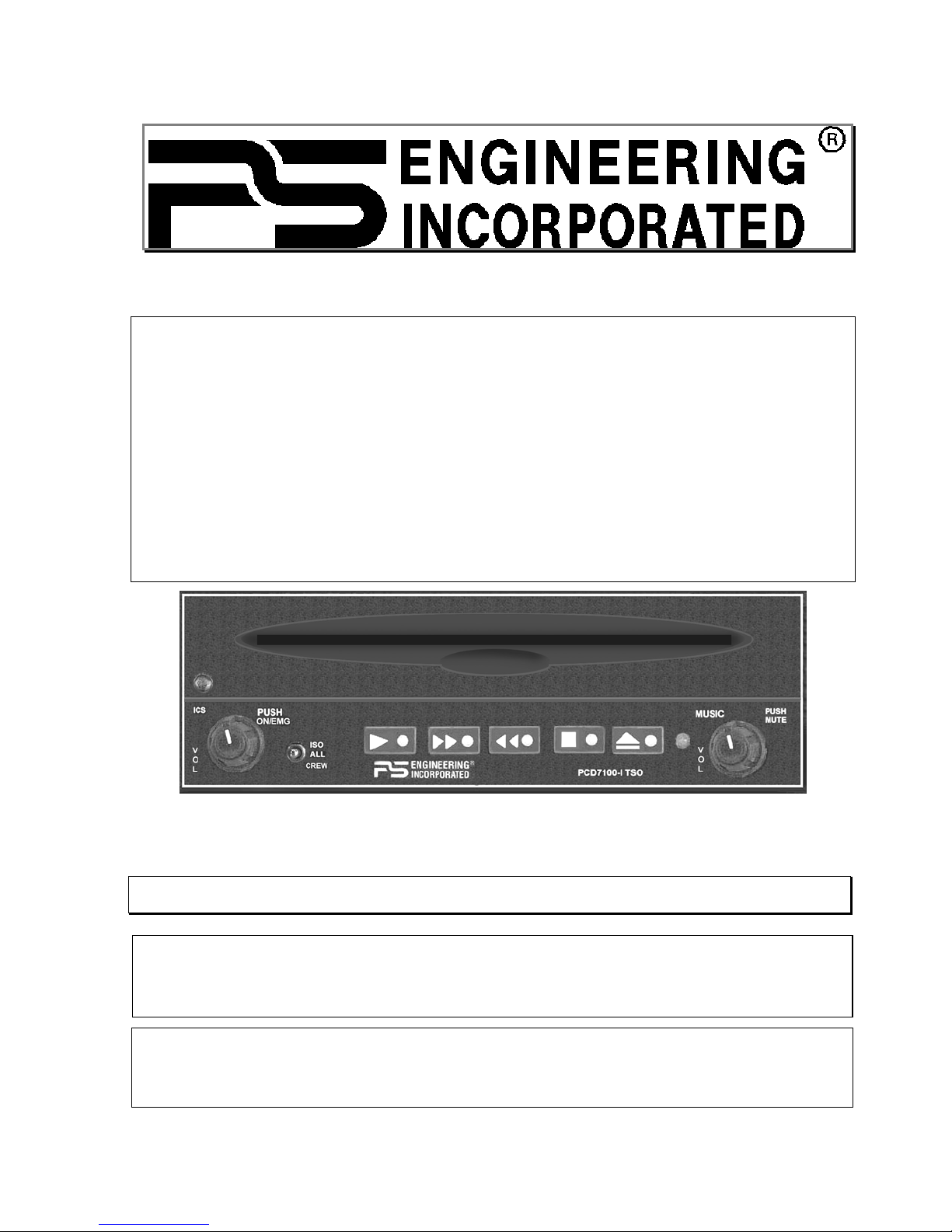
High-fidelity Stereo IntelliVox® Intercom
System
With integral music system
FAA-TSO C50c
JAA-Approved JTSO-C50c
US Patent 6,493,450
Installation and Operation Manual
Warranty is not valid unless this product is installed by an Authorized
PS Engineering dealer or a PS Engineering harness is purchased.
Any reproduction or retransmittal of this publication, or any portion thereof, without the expressed written permission of PS Engineering, Inc. is strictly prohibited. For further information contact the Publications Manager at PS Engineering, Inc., 9800 Martel
Road, Lenoir City, TN 37772. Phone (865) 988-9800.
Document P/N 200-971-0005
Revision 5
January 2003
PS Engineering, Inc. 2002 ©
Copyright Notice
Page 2

Table of Contents
SECTION I GENERAL INFORMATION........................................................................ 1-1
1.1 INTRODUCTION........................................................................................................... 1-1
1.2 SCOPE ............................................................................................................................. 1-1
1.3 EQUIPMENT DESCRIPTION ..................................................................................... 1-1
1.4 APPROVAL BASIS ........................................................................................................ 1-1
1.5 SPECIFICATIONS......................................................................................................... 1-2
1.6 EQUIPMENT SUPPLIED ............................................................................................. 1-3
1.7 EQUIPMENT REQUIRED BUT NOT SUPPLIED .................................................... 1-3
1.8 LICENSE REQUIREMENTS ....................................................................................... 1-3
SECTION II - INSTALLATION........................................................................................ 2-1
2.1 GENERAL INFORMATION ........................................................................................ 2-1
2.1.1 SCOPE ...........................................................................................................................2-1
2.2 U
2.3 E
2.3.1 C
2.3.2 M
2.3.3 M
2.3.4 C
2.4 C
2.4.1 N
2.4.2 P
2.4.3 C
2.4.4 B
2.4.5 I
2.4.6 P
2.4.7 U
2.4.8 U
2.4.9 A
2.5 A
2.6 P
2.7 U
2.7.1 I
2.7.2 CD P
2.8 I
2.9 F
NPACKING AND PRELIMINARY INSPECTION
QUIPMENT INSTALLATION PROCEDURES
OOLING REQUIREMENTS
OUNTING REQUIREMENTS
OUNTING RACK INSTALLATION
ONNECTOR ASSEMBLY
ABLE HARNESS WIRING
OISE
............................................................................................................................. 2-2
OWER
............................................................................................................................ 2-2
OMMUNICATIONS PUSH-TO-TALK
ACKLIGHTING
NTERCOM WIRING
LAYBACK INSTALLATION
NSWITCHED AUDIO INPUT
NSWITCHED SUMMED AUDIO
UDIO MESSAGE SYSTEM
DJUSTMENTS
OST INSTALLATION CHECKOUT
NIT INSTALLATION
NTERCOM CHECKOUT
LAYER CHECKOUT
NTERNAL RECORDER CHECKOUT (OPTIONAL
INAL INSPECTION
.............................................................................................................. 2-3
(11950, 11951, 11956, 11957) .............................................. 2-3
.................................................................................................................. 2-4
........................................................................................................... 2-6
.............................................................................................. 2-1
........................................................................................... 2-1
.................................................................................. 2-1
................................................................................................ 2-2
................................................................................................ 2-2
............................................................................... 2-2
(11951, 11957) ................................................................... 2-4
(11950, 11951, 11956, 11957........................................... 2-4
(11952, 11953, 11958)................................................ 2-4
(11953, 11954
................................................................................... 2-5
........................................................................................................ 2-5
(11950, 11951
................................................................................................. 2-6
.................................................................... 2-1
ONLY
11956, 11957
................................................................ 2-1
) .......................................................... 2-4
)....................................................... 2-5
) ........................................................... 2-6
SECTION III OPERATION ............................................................................................... 3-1
3.1 SCOPE ............................................................................................................................. 3-1
3.2 P
3.3 I
3.3.1 I
3.3.2 I
3.3.3 M
3.3.4 I
3.4 O
3.5 I
3.5.1 O
OWER SWITCH (FAIL SAFE OPERATION
NTERCOM OPERATION
NTERCOM VOLUME CONTROL
NTELLIVOX
USIC 1 AND SOFT MUTE CONTROL
NTERCOM MODES
PERATING THE INTERNAL
NTERNAL RECORDER SYSTEM (OPTIONAL
PERATION
® VOX-S
..................................................................................................................... 3-4
)..................................................................... 3-1
................................................................................................... 3-1
...................................................................................... 3-1
QUELCH
....................................................................................... 3-1
............................................................................. 3-2
......................................................................................................... 3-2
LAYER
CD P
....................................................................... 3-4
) ................................................................. 3-4
Page 3

3.6 PCD7100-P CD P
3.6.1 P
3.6.2 O
3.6.3 T
3.6.4 A
OWER/VOLUME KNOB
PERATING THE INTERNAL
ONE CONTROL
UDIO MESSAGING SYSTEM
PCD7100 Series Intercom System with Integral Music System
Installation and Operator’s Manual
LAYER ONLY (PART NUMBER
PS Engineering
11952
AND
11953) ............................ 3-5
.................................................................................................. 3-5
LAYER
CD P
........................................................................ 3-5
.............................................................................................................. 3-5
(11953
ONLY
)................................................................... 3-5
SECTION IV- WARRANTY AND SERVICE.................................................................. 4-1
4.1 W
4.2 F
APPENDIX B – INSTALLATION DRAWING
7.1 PCD7100 W/I
7.2 PCD7100 W/
ARRANTY
ACTORY SERVICE
...................................................................................................................... 4-1
.......................................................................................................... 4-1
APPENDIX A EXTERNAL PTT HOOK UP......................................................................A
........................................................... B
APPENDIX C CONNECTOR INTERCONNECT..............................................................C
NTERCOM
OUT INTERCOM
(11950, 11951) ............................................................................C
(11952, 11953) .................................................................... B
APPENDIX D- INSTRUCTIONS FOR FAA FORM 337 AND CONTINUING
AIRWORTHINESS ......................................................................................................................D
8.1 I
8.2 I
NSTRUCTIONS FOR
NSTRUCTIONS FOR CONTINUING AIRWORTHINESS
FAA F
APPENDIX E RTCA DO160D/EUROCAE ED-14D ENVIRONMENTAL
ORM
337, PCD7100S..............................................................D
, PCD7100S....................................D
QUALIFICATION FORM INTERCOM/CD PLAYER .........................................................E
200-971-0005 Page ii Rev. 5, Dec. 2002
Page 4

PCD7100 Series Intercom System with Integral Music System
Installation and Operator’s Manual
PS Engineering
Section I GENERAL INFORMATIO
N
1.1 INTRODUCTION
Quality cockpit and cabin entertainment has long been an elusive dream in general aviation. From marginal
performance to unapproved parts, pilots couldn’t enjoy the same music in their aircraft as they could in the
family car.
The PCD7100-Series represents such a product. This one unit combines intercommunications and a compact disk player for ultimate functionality. Using proprietary IntelliVox® design, this intercom eliminates
the requirements for intercom squelch adjustments. The CD player is designed for simple operation, avoiding any increase in cockpit workload from complicated controls.
Before installing and/or using this product, please read this manual completely. This will ensure that you
will take full advantage of all the advanced features in the PCD7100.
1.2 SCOPE
This manual provides detailed installation and operation instructions for the PS Engineering PCD7100series of CD Player/Intercom Systems. This includes the following units:
Model Part Number Description
PCD7100-I 11950 CD Player w/6-place ICS
PCD7100-I 11951 CD Player w/6-place ICS and /Internal Recorder
PCD7100-P 11952 CD Player only
PCD7100-P 11953 CD Player only w/Audio Warning System
PCD7100-P 11954 CD/MP3 Player Only w/Audio Warning System
PCD7100-I 11956 CD/MP3 Player w/6-place ICS
PCD7100-I 11957 CD/MP3 Player w/6-place ICS and /Internal Recorder
PCD7100-P 11958 CD/MP3 Player only
Where the functions are identical to all units, it will be referred to herein as a PCD7100. Otherwise, the
applicable units will be specified.
1.3 EQUIPMENT DESCRIPTION
The PCD7100-series is a state of the art intercom with PS Engineering’s proprietary IntelliVox® automatic
voice activated (VOX) intercom system, that contains an integrated Compact Disk (CD) player.
A six-station voice activated (VOX) intercom is included in the PCD7100-I (p/n 11950, 11951, 11954,
11956). This system has PS Engineering’s exclusive IntelliVox® circuitry that eliminates manual adjustments. The system contains six separate VOX mic circuits, and only opens the microphone channel in use.
The intercom system incorporates pilot isolate and crew modes.
There are two stereo music inputs with "Soft Mute." SoftMute is a circuit that automatically mutes the
music during radio or intercom activity, and then slowly returns the music to full volume after the activity
ceases.
Intercom control is through front panel-mounted volume knobs and 3-position mode switch. A single volume controls intercom level for the pilot and copilot. Passenger headphone volume is factory set, and adjusted in flight with headset-mounted volume controls. Passenger volume control is further adjustable
through screwdriver access in the top of the unit. Intercom squelch is automatic.
1.4 APPROVAL BASIS
TSO Approval.
200-971-0005 Page 1-1 Rev. 5, Dec. 2002
Page 5

PCD7100 Series Intercom System with Integral Music System
Installation and Operator’s Manual
PS Engineering
The PCD7100, is FAA approved under TSO C50c (Audio Amplifiers), /DO-178B (Software Considerations for Airborne Equipment) and DO-214 (Audio Systems Characteristics and Minimum Operational
Performance Standards for Aircraft Audio Systems). In addition, the system is approved under Joint Avia-
tion Authorities JTSO C50c.
All systems comply with relevant portions of EUROCAE ED-14D/DO-160D (Environmental Conditions
and Test Procedures for Airborne Equipment), ED12B/DO-178B (Software Considerations for Airborne
Equipment) and ED- 18/DO-214 (Audio Systems Characteristics and Minimum Operational Performance
Standards for Aircraft Audio Systems).
Operation is subject to the following conditions: This device may not cause harmful interference.
This device must accept any interference received, including interference that may cause undesired operation.
1.5 SPECIFICATIONS
TSO COMPLIANCE
Audio Selector/Intercom: C50c, Class A
APPLICABLE DOCUMENTS: RTCA/DO-214
RTCA/DO-160D
RTCA/DO-178B (Level E)
ENVIRONMENTAL Qualifications: B1CABSRXXXXXXABBBBTMXXE2
Temperature Range:
Operating:
Storage:
-15º C to 55ºC
-40º C to 85ºC
Altitude: Up to 25,000 feet in an non-pressurized area of the cock-
pit.
DIMENSIONS: Height: 2.0 in. (5.1 cm) Width: 6.25 in. (15.9 cm)
Depth: 7.8 in. (19.8 cm)
WEIGHT (With Rack & Connectors): 2.2 lb. (1.0 kg)
POWER REQUIREMENTS (Including Internal Lighting):
Voltage: 11 to 33 VDC
Maximum Current:
11950, 11951
11952, 11953
2.0 Amp (Externally protected by a 3 Amp pull type
circuit breaker.
1.5 Amp (Externally protected by a 2 Amp circuit pulltype breaker.)
Typical operating current: 800 mA
Intercom Specifications
Headphone Impedance:
150 - 1000 Ω
Headphone Output: 35 mW each headset channel, no clipping <1% THD
Microphone Impedance:
Intercom Positions (11950, 11951,
150 - 600 Ω
6 places (with individual IntelliVOX circuits)
11954, 11956, 11957):
Music Inputs: 2 (Stereo)
Music Muting: >-50 dB "Soft Mute" when Com or intercom active.
Distortion:
<1% THD @ 35 mW into 150Ω
Mic Freq. Response, 3 dB: 300 Hz - 6000 Hz
Music Freq. Response, 3 dB: 20 Hz –20 kHz
200-971-0005 Page 1-2 Rev. 5, Dec. 2002
Page 6

PCD7100 Series Intercom System with Integral Music System
Installation and Operator’s Manual
PS Engineering
1.6 EQUIPMENT SUPPLIED
1 ea. of the following units:
Model Part Number Description
PCD7100-I 11950 CD w/6-place ICS
PCD7100-I 11951 CD w/6-place ICS w/IRS
PCD7100-P 11952 CD only
PCD7100-P 11953 CD only w/AWS
PCD7100-P 11954 CD/MP3 Player Only w/Audio Warning System
PCD7100-I 11956 CD/MP3 Player w/6-place ICS
PCD7100-I 11957 CD/MP3 Player w/6-place ICS and /Internal Recorder
PCD7100-P 11958 CD/MP3 Player only
PCD7100 Installation Kit: 250-971-0001 or 250-972-0400 as shown
Part Number Description 250-971-0001
Unit Part Number
11950, 11951, 11953,
11954, 11956, 11957
120-430-9701 Tray 1 1
120-425-4402 44 Pin Connector Key 4/5 1 1
425-001-0002 Gold Plated Crimp Pins 35 10
475-440-0007 4-40x7/16" Phil-Pan w/Nylon
Patch
475-630-0002 6-32 Clip Nut 4 4
200-971-00XX Operator's and Installation
Manual
2 2
1 1
250-972-0400
Unit Part Number
11952, 11958
1.7 EQUIPMENT REQUIRED BUT NOT SUPPLIED
a) Circuit Breaker, PULL TYPE: 1 ea. 3 amp (11950, 11951, 11954, 11956, 11957) or 2 amp
(11952, 11953, 11958)
b) Headphone Jacks (Stereo, up to 6 as required)
c) Microphone Jacks (up to 6 as required)
d) Headphones, 150 Ω (Stereo), up to 6 as required
e) Microphones, up to 6 as required
f) Interconnect Wiring
g) Intercom or audio system (11952, 11958, 11953, 11954)
1.8 LICENSE REQUIREMENTS
None
200-971-0005 Page 1-3 Rev. 5, Dec. 2002
Page 7

PCD7100 Series Intercom System with Integral Music System
Installation and Operator’s Manual
PS Engineering
Section II - Installation
2.1 GENERAL INFORMATION
2.1.1 SCOPE
These sections provide detailed installation and interconnect instructions for the PCD7100-Series Intercom
System with internal Compact Disc (CD) Player.
Please read this manual carefully before beginning any installation to prevent damage and post-installation
problems. Installation of this equipment requires special tools and knowledge.
NOTE: An appropriately rated Certified Aircraft Repair Station must install this equipment in accordance
with applicable regulations. PS Engineering, Incorporated warranty is not valid unless the equipment is
installed by an authorized PS Engineering, Incorporated dealer. Failure to follow any of the installation
instructions, or installation by a non-certified individual or agency will void the warranty, and may result in
an unairworthy installation.
2.2 Unpacking and Preliminary Inspection
Use care when unpacking the equipment. Inspect the units and parts supplied for visible signs of shipping
damage. Examine the unit for loose or broken buttons, bent knobs, etc. Verify the correct quantity of components supplied with the list in Section 1.6 (B). If any claim is to be made, save the shipping material and
contact the freight carrier. Do NOT return units damaged in shipping to PS Engineering. If the unit or accessories shows any sign of external shipping damage, contact PS Engineering to arrange for a replacement. Under no circumstances attempt to install a damaged unit in an aircraft. Equipment returned to PS
Engineering for any other reason should be shipped in the original PS Engineering packaging, or other
UPS approved packaging.
2.3 Equipment Installation Procedures
2.3.1 Cooling Requirements
Forced air-cooling of the PCD7100 is not required. However the unit should be kept away from heat producing sources (i.e. defrost or heater ducts, dropping resistors, heat producing avionics) without adequate
cooling air provided.
2.3.2 Mounting Requirements
The PCD7100 must be rigidly mounted to the instrument panel or other structure of the aircraft structure
and within view and reach of the persons wishing access. Installation must comply with FAA Advisory
Circular AC 43.13-2A (or later revision). The unit may be mounted in any area where adequate clearance
for the unit and associated wiring bundle exist.
The unit must be installed within ±30° of horizontal along the pitch axis, and ±10° of horizontal along the
roll axis in level flight.
Avoid installing the PCD7100 close to high current devices or systems with high-voltage, pulse type outputs, such as DME or transponders.
2.3.3 Mounting Rack Installation
Remove the unit from the mounting tray by unscrewing the 3/32" hex-head screw that is near the left edge
of the unit. Carefully slide the unit free of the tray. Set the unit aside in a safe location until needed. Install
the tray using six FHP 6-32 x ½" screws. The unit must be supported at front and rear of the mounting tray.
200-971-0005 Page 2-1 Rev. 5, Dec. 2002
Page 8

PCD7100 Series Intercom System with Integral Music System
Installation and Operator’s Manual
PS Engineering
2.3.4 Connector Assembly
The unit connector mates directly with the circuit boards in the PCD7100. The connector is a Molex crimptype, and requires the use of a Molex hand crimp tool, EDP P/N 11-01-0203, CR6115B (or equiv.). The
connector is mounted to the unit tray with #4-40 screws, from the inside of the tray. Ensure that proper
strain relief and chafing precautions are made during wiring and installation.
2.4 Cable Harness Wiring
Referring to the appropriate Appendix, assemble a wiring harness as required for the installation. All wires
must be MIL-SPEC in accordance with current regulations. Two- and three-conductor shielded wire must
be used where indicated, and be MIL-C-27500 or equivalent specification. Proper stripping, shielding and
soldering technique must be used at all times. It is imperative that correct wire be used.
Refer to FAA Advisory Circular 43.13-2A for more information. Failure to use correct techniques may
result in improper operation, electrical noise or unit failure. Damage caused by improper installation will
void the PS Engineering warranty. PS Engineering can provide a custom made harness, visit www.ps-
engineering.com for more information.
2.4.1 Noise
Due to the variety and the high power of radio equipment often found in today's general aviation aircraft,
there is a potential for both radiated and conducted noise interference.
The PCD7100 power supply is specifically designed to reduce conducted electrical noise on the aircraft
power bus by at least 50dB. Although this is a large amount of attenuation, it may not eliminate all noise,
particularly if the amplitude of noise is very high. There must be at least 12 VDC present at the connector
pin 21, of the PCD7100 for the power supply to work in its designed regulation. Otherwise, it cannot adequately attenuate power line noise. Shielding can reduce or prevent radiated noise (i.e., beacon, electric
gyros, switching power supplies, etc.) However, installation combinations can occur where interference is
possible. The PCD7100 was designed in a RFI hardened chassis and has internal Electromagnetic Interference (EMI) filters on all inputs and outputs.
Ground loop noise occurs when there are two or more ground paths for the same signal (i.e., airframe and
ground return wire). Large cyclic loads such as strobes, inverters, etc., can inject noise signals onto the
airframe that are detected by the audio system. Follow the wiring diagram very carefully to help ensure a
minimum of ground loop potential. Use only Mil Spec shielded wires (MIL-C-275000, or better).
Radiated signals can be a factor when low level microphone signals are "bundled" with current carrying
power wires. Keep these cables physically separated. It is very important that you use insulated washers to
isolate the ground return path from the airframe to all headphone and microphone jacks.
2.4.2 Power
The PCD7100-Series units are compatible with both 14 and 28 Volt DC systems. A three- (3) Amp PULLTYPE circuit breaker is required for p/n 11950, 11951, or two (2) Amp PULL-TYPE breaker for p/n
11951, or 11952. Power and ground wires must be a twisted
#18 AWG pair. Connect airframe power
ground to Pin 22 only.
2.4.3 Communications Push-to-Talk
An important part of the standard intercom installation (11950, 11951) is the PTT (Push-To-Talk) switches
that allow the use of your aircraft communications radio for transmissions. There are three typical configurations that can be used. Select the case that best fits the installation. Only the person who presses their
PTT switch will be heard over the radio. If the pilot and copilot both use the PTT, the only pilot position
has access to the radio. The pilot position will have PTT control regardless of the mic selector switch or
copilot PTT when the PCD7100 is in the F
200-971-0005 Page 2-2 Rev. 5, Dec. 2002
AIL-SAFE
mode.
Page 9

PCD7100 Series Intercom System with Integral Music System
Installation and Operator’s Manual
PS Engineering
CASE I: PTT is built into both pilot and copilot yokes.
CASE II: PTT is in pilot yoke only. This configuration requires a modified external PTT switch plugged
into the copilot's microphone jack. (See Appendix A). When the copilot's PTT is pressed, the intercom
switches the microphone audio from pilot to copilot mic.
CASE III: No built in PTT. This requires two built in PTTs to be installed, or modified external PTT
switches to be used. Modify external PTT as required (See Appendix A).
No Push to Talk is required for CD-only (11952, 11953).
2.4.4 Backlighting
The PCD7100 has an automatic dimming of the pushbutton annunciator LEDs controlled by a photocell. A
dimmer control allows the bezel text backlighting to be controlled by the aircraft dimmer. Connect the 14
V dimmer control to pin 1, the 28 V dimmer to pin A, as required.
2.4.5 Intercom wiring (11950, 11951, 11956, 11957 only)
See Appendix for intercom connection configurations. It is critical to the proper operation of this system to
have this connector wiring made in accordance with these diagrams. Use 2- and 3-conductor, MIL-spec
cable as shown. Connect the shields at the PCD7100 end only, and tie to the audio low inputs as shown.
NOTE: The harness can be custom made by PS Engineering, Inc. Simply call the factory or access
www.ps-engineering.com on the internet to obtain a wire harness work-sheet. The harness will be made to
your specifications and fully functionally tested. All hardware is included.
2.4.5.1 Entertainment 2 Input
NOTE: Use the low-level
output of any entertainment device to connect to the
PCD7100. Minimum of 1 VAC p-p, maximum signal level is 3 VAC p-p.
DO NOT use a speaker-level output, this will cause internal damage in the PCD7100
An additional stereo entertainment device (CD player, cassette player, etc.) can be connected to the unit.
Install a
1
/8-inch stereo jack in a convenient location so that the pilot can plug in the entertainment devices
into the system. The audio signal at the entertainment input must be a minimum of 1 V P-P per channel for
optimum music performance.
All external entertainment devices must be switched off for both takeoff and landing.
2.4.5.1.1 Entertainment distribution
Entertainment source #1 (CD player) provides music for the pilot and copilot positions in crew mode and
everybody in ALL. Entertainment source #2 provides music for the four passenger positions in crew mode
only. The PCD7100-system incorporates a "Soft Mute" for the CD player. This will mute the music during
ICS or radio conversation.
Entertainment inputs #1 and #2 can be paralleled (connected together) so the internal CD entertainment
source can serve both the passengers and the crew. However, we suggest that a switch (DPDT) is installed
between the single entertainment device and entertainment input #1 to allow entertainment flexibility.
Caution: Local oscillators and internal signals from some entertainment equipment can cause undesired
interference with other aircraft systems. Before takeoff, operate the entertainment devices to determine if
there is any adverse effect within the aircraft systems. If any unusual operation is noted in flight, immediately switch off the entertainment devices.
Both entertainment devices must be switched off for both takeoff and landing.
200-971-0005 Page 2-3 Rev. 5, Dec. 2002
Page 10

PCD7100 Series Intercom System with Integral Music System
Installation and Operator’s Manual
PS Engineering
2.4.6 Playback Installation (11951, 11957 only)
To install the IRS, a momentary, normally open, push button switch is required. This switch can be located
any where in cockpit convenient to the pilot's reach. The switch must be connected to pin Y of the
PCD7100.
2.4.7 Unswitched Audio Input (11950, 11951, 11956, 11957 only)
The PCD7100-I has an audio input that is provided to the pilot headset. Pins 16 (right) and 18 (left) with
respect to audio low (pin E) are presented to the pilot headset through an audio buffer.
2.4.8 Unswitched Summed Audio (11952, 11953, 11954, 11958 only)
PCD7100-P, player units have four audio inputs that are summed together and presented to the aural warning output, J1 pin 18 WRT V.
NOTE: These can be used to implement additional audio warnings when connected to the appropriate
Unswitched audio input of an audio panel. This includes Autopilot warnings, TAWS, GPS alerts, Radio
Altimeter, etc.
2.4.9 Audio Message System (11953, 11954 only)
The audio message installation requires inputs from an external annunciator, such as an Electronics International engine gage system. A falling edge (input pulled low) when applied to the appropriate pin of the
connector will cause the message to be played, repeating every two seconds, until the acknowledge
(“ACK”) button is pushed.
Install the “ACK” button in a location convenient to the pilot and copilot position. This switch is a momentary SPST switch between Pin 4 and signal ground (18).
The following table contains information regarding various inputs.
Function EGT or CHT Fuel
Flow or
Level
Oil Pres-
sure or
temperature
Volt/
Amp
RPM Manifold
Pressure
PCD7100 Pin 5 8 6 9 7 10
Message Number 1 2 3 4 5 6
Message Text “Check tem-
perature”
“Check
fuel”
“Check
oil”
“Check
battery”
“Check engine speed”
“Check boost”
Other combinations can be created at additional cost.
NOTE: PS Engineering can only provide input information at this time. Approval basis is the responsibil-
ity of the installer. Contact PS Engineering for more information.
2.5 Adjustments
The PCD7100 is factory adjusted to accommodate the typical requirements for most aircraft configurations. The only service adjustment is passenger headset volume control. These are set for maximum at the
factory, but may be attenuated at installation if desired by accessing two adjustment pots.
200-971-0005 Page 2-4 Rev. 5, Dec. 2002
Page 11

PCD7100 Series Intercom System with Integral Music System
Installation and Operator’s Manual
PS Engineering
Passenger Intercom
volume (L)
Front of Unit
Passenger Intercom
volume (R)
Figure 2-1- PCD7100 Adjustments
2.6 Post Installation Checkout
After wiring is complete, verify power is ONLY on pin 21 of the connector, and airframe ground on bottom connector pin 22. Failure to do so will cause serious internal damage and void PS Engineering's warranty.
2.7 Unit Installation
To install the PCD7100, gently slide the unit into the mounting rack until the hold-down screw is engaged.
While applying gentle pressure to the face of the unit, tighten the 3/32" hex-head in the unit until it is secure. DO NOT OVER TIGHTEN.
Warning: Do not over-tighten the lock down screw while installing the unit in tray.
Internal damage will result.
Play/Pause Skip-FF Repeat-RW Stop Eject
2.7.1 Intercom Checkout (11950, 11951, 11956, 11957)
1. Apply power to the aircraft and avionics. Leave PCD7100 off.
2. Plug headsets into the pilot, copilot, and occupied passenger positions.
3. Verify correct fail-safe operation by listening and transmitting on the aircraft radios in the pilot’s head-
set with the unit off. The audio will only be presented to the pilot’s right ear, in stereo mode.
4. Switch on the PCD7100. Verify that the STOP LED (Light Emitting Diode) shows green if there is a
CD in the unit, or the Eject LED if there is not a CD inside.
5. Verify proper transmit and receive operation from the pilot and copilot positions, noting that the copi-
lot PTT switch allows proper transmission on the selected transceiver.
200-971-0005 Page 2-5 Rev. 5, Dec. 2002
Page 12

PCD7100 Series Intercom System with Integral Music System
Installation and Operator’s Manual
6. Verify proper Intercom system operation in the ALL
PS Engineering
SO and CREW modes (see Table 3-1).
, I
7. Verify that the PCD7100 system does not adversely affect any other aircraft system by systematically
switching the unit on and off and changing modes, while monitoring the other avionics and electrical
equipment on the aircraft.
2.7.2 CD Player Checkout
8. Insert CD, and verify that the player accepts the disk with about ½ of the diameter in the unit. The
player should pull the disk smoothly and drop into place.
9. The CD player will begin to play, automatically.
10. If the CD is inside at power-up, push the “play” button.
11. Verify that all CD modes operate.
12. Push the “Eject” button and verify that the disc is ejected within about 10 seconds.
2.8 Internal Recorder Checkout (Optional)
With headset plugged into pilot’s side jacks, tune aircraft radio to local frequency, such as FSS or ATC
ground.
Select Com 1 on mic selector switch, and record at least five incoming radio transmissions.
This audio should only appear in one side of the pilot’s headset, and it should be radio (or sidetone) traffic.
Depress the panel or yoke mounted playback switch, and verify that all five messages play, in the order
received.
2.9 Final Inspection
Verify that the wiring is bundled away from all controls and no part of the installation interferes with aircraft control operation. Move all controls through their full range while examining the installation to see
that no mechanical interference exists. Verify that the cables are secured to the aircraft structure in accordance with good practices, with adequate strain relief. Ensure that there are no kinks or sharp bends in the
cables and coaxial cables. Verify that the cables are not exposed to any sharp edges or rough surfaces, and
that all contact points are protected from abrasion.
Complete logbook entry, FAA Form 337, weight and balance computation and other documentation as
required. Sample text for FAA Form 337 and instructions for continuing airworthiness can be found in
Appendix F.
Return completed warranty registration application to PS Engineering.
200-971-0005 Page 2-6 Rev. 5, Dec. 2002
Page 13

PCD7100 Series Audio Selector Panel and Intercom System
Installation and Operator’s Manual
PS Engineering
Section III OPERATION
GENERAL INFORMATION
3.1 SCOPE
This section provides detailed operating instructions for the PS Engineering PCD7100-I, Intercom Systems
with integrated Compact Disc (CD) player, and PCD7100-P, CD player only. Please read it carefully before using the equipment so that you can take full advantage of its capabilities.
INTERCOM
PUSH
3.2 Power Switch (Fail Safe Operation)
ON-OFF
Unit power is turned on and off by pushing the intercom volume knob. In the
VOLUME
INTERCOM MODE
pilot is connected directly to the aircraft radios. This allows communication capability regardless of unit
condition. Any time power is removed or the unit turned
Figure 3-1 PCD7100 controls
PLAY SKIP FWD SKIP BACK STOP
OFF
, the intercom will be placed in the fail-safe
OFF
EJECT
MUSIC
VOLUME
PUSH
MUTE
CONTROL
or "EMG" position, the
mode.
3.3 Intercom Operation
3.3.1 Intercom Volume Control (11950, 11951, 11956, 11957)
The ICS volume control knob (left side) adjusts the loudness of the intercom for the pilot and copilot only.
It has no effect on selected radio levels, music input levels or passengers' volume level.
Adjust the radios and intercom volume for a comfortable listening level for the pilot. Most general aviation
headsets today have built-in volume controls; therefore, passenger volume can be adjusted at the headset.
3.3.2 IntelliVox® VOX-Squelch
No adjustment of the IntelliVox® squelch control is necessary. Through independent signal processors on
each microphone, the ambient noise appearing in all microphones is constantly being sampled. Non-voice
signals are blocked. When someone speaks, only their microphone circuit opens, placing their voice on the
intercom.
The system is designed to block continuous tones, therefore people humming or whistling in monotone
may be blocked after a few moments.
For best performance, the headset microphone must be placed within ¼ inch of your lips, preferably
against them. It is also a good idea to keep the microphone out of a direct wind path. Moving your head
through a vent air stream may cause the IntelliVox® to open momentarily. This is normal.
For optimum microphone performance, PS Engineering, Inc. recommends installation of a Microphone
Muff Kit from Oregon Aero (1-800-888-6910). This will not only optimize VOX performance, but will
improve the overall clarity of all your communications.
200-971-0005 Page 3-1 Rev. 5, Dec. 2002
Page 14

PCD7100 Series Audio Selector Panel and Intercom System
Table 3-1 Mic Muff ® Part Numbers
Manufacturer Model Mic Muff® Part
Bose Dynamic
David Clark H10-30
Lightspeed 15K & 20K 90015
PS Engineering
Installation and Operator’s Manual
90010
Electret
M87 Dynamic
90015
90020
90010
H10-20, H10-40
H10-13.4
90015
90015
Number
Peltor 7003
7004
90010
90015
Pilot 11-20 & 11-90 90015
Sennheiser 90015
Telex Airman 750
AIR3000
90015
90010
3.3.3 Music 1 and Soft Mute Control
The right-side volume knob controls the loudness of the internal CD player.
The volume knob controls the music volume only, it has no effect on the intercom or radio volume, or the
secondary music input level.
This knob is also the Soft Mute control for the CD player. Normally, the music is instantly muted during
radio or intercom conversation, and returns gradually to full volume when conversation stops. Pushing the
knob once will inhibit the soft mute, enabling a “Karoake” mode, where the music remains at he normal
level for a sing-along. Push again to return to a soft muting mode.
3.3.3.1 Mono headsets in Stereo Installation
Plugging a mono headset into the pilot or copilot jacks has no effect other than there will be no stereo left
and right separation. Since all passenger headsets are connected in parallel, if a monaural headset is
plugged in to a PCD7100 Stereo installation, one channel will be shorted. Although no damage to the unit
will occur, all stereo-equipped passengers will lose one channel. PS Engineering modifies headsets to add
stereo capability, using high-fidelity speakers. Contact factory for details (865-988-9800 or www.psengineering.com).
3.3.4 Intercom Modes
On the left side of the intercom-versions is a 3-position mode switch that allows the pilot to tailor the intercom function to best meet the current cockpit situation.
SO
: (Up Position): The pilot is isolated from the intercom and is connected only to the aircraft radio sys-
I
tem. He will hear the aircraft radio reception (and sidetone during radio transmissions). Copilot and passengers will hear intercom and CD player. Neither will hear aircraft radio receptions or pilot transmissions.
200-971-0005 Page 3-2 Rev. 5, Dec. 2002
Page 15

PCD7100 Series Audio Selector Panel and Intercom System
Installation and Operator’s Manual
PS Engineering
ALL: (Middle Position): All parties will hear the aircraft radio, CD music and intercom. During any radio
or intercom communications, the music volume automatically decreases (unless the mute is inhibited). The
music volume will gradually return to the original level after communications have been completed.
REW (Down Position): Pilot and copilot are connected on one intercom channel and have exclusive ac-
C
cess to the aircraft radios. They may also listen to CD music. Passengers can continue to communicate with
themselves without interrupting the Crew and also may listen to Entertainment 2. Entertainment 2 may be
connected to the CD player during installation if so desired.
3.3.4.1 Soft Mute and Soft Mute inhibit
The Soft Mute feature assures that the aircraft radio transmissions will not be missed due to entertainment
playing. When there is radio reception or intercom conversation, the music level is dropped to a low, or
background level. When the radio or intercom traffic ceases, the level gradually returns to normal.
The front panel “MUTE” switch controls muting of the CD player. Pushing the music volume knob places
the ICS in Karoake (or sing along) mode, which inhibits the soft mute feature. This allows the music to
continue uninterrupted by intercom or radio traffic when cockpit workload is appropriate. Pushing the knob
again will release the mute inhibit function.
Table 3-2 Intercom Modes
Mode Pilot Hears Copilot Hears Passenger Hears Comments
Isolate
All
Crew
A/C Radios
Pilot Sidetone (during
radio transmission) CD
is Muted
Pilot
Copilot
A/C Radio
Passengers
CD player
Pilot
Copilot
A/C Radio
CD Player
Copilot and passenger
intercom
CD player
Copilot
Pilot
A/C Radio
Passengers
CD player
Copilot
Pilot
A/C Radio
CD Player
Passenger and Copilot
intercom
CD Player
Passengers
Pilot
Copilot
A/C Radio
CD player
Passengers
Entertainment #2*
This mode allows the pilot
to communicate without
the others bothered by the
conversations. Copilot and
passengers can continue
to communicate and listen
to music
This mode allows all on
board to hear radio reception as well as communicate on the intercom. Music is muted during
intercom and radio communications
This mode allows the pilot
and copilot to concentrate
on flying, while the passengers can communicate
amongst themselves. Two
separate music inputs are
possible.
3.3.4.2 Secondary Entertainment Input
The PCD7100 has provisions for an additional entertainment input. The primary music volume control
does not affect secondary music level.
REW
While in the C
mode, pilot and copilot will hear entertainment input #1 while the passengers may lis-
ten to entertainment input #2.
It is also possible to use only one entertainment input device for both entertainment inputs. It is suggested
however, that a switch (DPDT) is installed between the single entertainment device and entertainment input #1. This will allow the passengers to play the CD while in the Crew mode.
200-971-0005 Page 3-3 Rev. 5, Dec. 2002
Page 16

PCD7100 Series Audio Selector Panel and Intercom System
Installation and Operator’s Manual
PS Engineering
3.4 Operating the internal disc Player
The single-disk CD player is designed for simple operation. There are five buttons with the following functions.
► (Play) Plays disc, push again to pause
►► (Jump Forward) Push to jump to the next track, hold to fast forward in current track
◄◄ (Jump Backward) Push to jump to the previous track, hold to rewind in current track
(Stop) Stops playback
(Eject) Ejects disc
▲
The CD player will begin to play automatically when a CD is inserted. Press the play button to pause the
track.
The jump forward button advances to the next track. Jump backwards selects the previous track.
On MP3 units (11954, 11956, 11957, 11958), pressing the Jump Forward and Jump Backward buttons at
the same time will toggle the unit into a random play mode. Random Mode is particularly useful if the disc
contains a large number of files.
Stop ceases play, and Eject removes the disk from the CD player.
3.5 Internal Recorder System (Optional)
The Intercom Recording System (referred to here as the IRS) is a digital recording system allowing automatic storage and immediate playback of all incoming aircraft radio receptions.
Operating as a continuous loop recorder, (first message received will be the last heard), the recorder has
one minute of recording time divided into as many as 16 messages. With its own built-in VOX circuit,
there are no buttons to press to start recording. The system automatically begins to record the instant the
radio becomes active. Only aircraft radio audio in pilot’s headset is recorded and only the pilot will hear
the playback audio, in one ear.
3.5.1 Operation
Recording is automatic; there is no action required by the pilot. To play back the last recorded message,
simply press the momentary switch associated with the IRS. Each additional press of the button will play
the preceding recorded message.
To stop playback, hold the playback button for two seconds. The next push will then play the prior message.
200-971-0005 Page 3-4 Rev. 5, Dec. 2002
Page 17

PCD7100 Series Audio Selector Panel and Intercom System
Installation and Operator’s Manual
PS Engineering
3.6 PCD7100-P CD Player Only (Part Number 11952, 11953, 11958 and 11959)
PUSH
ON-OFF
MUSIC
VOLUME
PLAY SKIP FWD SKIP BACK STOP
EJECT
MUSIC
TONE
ACK
3.6.1 Power/Volume Knob
Pushing the right-hand knob switches the PCD7100-P on. Push again to turn off. Rotate the knob to increase volume on the music output.
3.6.2 Operating the internal CD Player
The single-disk CD player is designed for simple operation. There are five buttons with the following functions.
► (Play) Plays CD, push again to pause
►► (Jump Forward) Push to jump to the next track, hold to fast forward in current track
◄◄ (Jump Backward) Push to jump to the previous track, hold to rewind in current track
(Stop) Stops playback
(Eject) Ejects disc
▲
The CD player will begin to play automatically when a CD is inserted. Press the play button to pause the
track.
The jump forward button advances to the next track. Jump backwards selects the previous track.
On MP3 units (11954, 11956, 11957, 11958), pressing the Jump Forward and Jump Backward buttons at
the same time will toggle the unit into a random play mode. Random Mode is particularly useful if the disc
contains a large number of files.
Stop ceases play, and Eject removes the disk from the CD player.
3.6.3 Tone Control
Turning the left-hand knob modifies the bass/treble of the music output to suit individual tastes.
3.6.4 Audio Messaging system (11953 and 11954 only)
When this option is installed, the PCD7100-P contains six stored messages. An outside annunciator, such
as an Electronics International engine gage system triggers these messages. When there is an announcement, it will be repeated every two seconds until the remote- mounted ACK button is pushed. This stops
the played annunciation, until the next announcement is required (the next falling edge).
200-971-0005 Page 3-5 Rev. 5, Dec. 2002
Page 18

PCD7100 Series Audio Selector Panel and Intercom System
Installation and Operator’s Manual
PS Engineering
3.6.4.1 Push ACK (11953, 11954 only)
Pushing the left-hand will acknowledge and silence a playing Aural Warning, if this feature is implemented
(Part number 11953 only).
3.7 Creating MP3s from an Audio CD
1. Start MusicMatch JukeBox.(www.musicmatch.com
) Press the recorder button, which is the
small red dot located in the top right corner. This will open the recorder window located at
the bottom of the screen.
2. Insert an audio CD into the CD drive. MusicMatch will automatically read the disc and display the contents in the recorder window. Press the REFRESH button to check the Internet
database for CD information, such as artist, song title, or album. If this information is available, it will automatically be updated in the file.
3. Select Options->Recorder->Format and select either MP3 or MP3PRO format. You may also
set the MP3 file quality under the Options->Recorder->Quality menu.
4. Select the tracks to be copied to MusicMatch by checking the box next to the desired track.
Press the record button in the lower left corner when complete
5. MusicMatch will then convert the files from the audio CD to MP3 and display them in the
Music Library box located in the middle of the screen
6. To edit the MP3 information, select a file in the Music Library and press the TAG button in
the top right corner of the Music Library box. This will display the MP3 tagged information
screen. Select the General tab to show the information that can be modified for the PXE7300.
7. The PXE7300 can display song name, artist, album, and filename. This corresponds to the
Track title, Artist, Album, and Track Filename fields shown on the screen. Each of these
fields can be modified to the user’s preference. Note: The PXE7300 is limited to displaying
up to 22 characters in each of these fields. Click on the appropriate field to modify the track
title, artist, or album. To modify the filename, select the Rename Files button in the lower left
corner. Click on the field labeled New File Name and press OK to change the file name. Press
the Apply and OK buttons to update the information
200-971-0005 Page 3-6 Rev. 5, Dec. 2002
Page 19

PCD7100 Series Audio Selector Panel and Intercom System
Installation and Operator’s Manual
PS Engineering
Section IV- Warranty and Service
4.1 Warranty
In order for the factory warranty to be valid, the installations in a certified aircraft must be accomplished by
an FAA-certified avionics shop and authorized PS Engineering dealer. If the unit is being installed by a
non-certified individual in an experimental aircraft, a factory-made harness must be used for the warranty
to be valid.
PS Engineering, Inc. warrants this product to be free from defect in material and workmanship for a period
of one (1) year from the date of installation as recorded in aircraft logbook and/or on FAA Form 337
ing the twelve (12) months, PS Engineering, Inc., at its option, will send a replacement unit
at our expense
if the unit should be determined to be defective after consultation with a factory technician.
All transportation charges for returning the defective units are the responsibility of the purchaser. All domestic transportation charges for returning the exchange or repaired unit to the purchaser will be borne by
PS Engineering, Inc. The risk of loss or damage to the product is borne by the party making the shipment,
unless the purchaser requests a specific method of shipment. In this case, the purchaser assumes the risk of
loss.
This warranty is not transferable. Any implied warranties expire at the expiration date of this warranty. PS
Engineering SHALL NOT BE LIABLE FOR INCIDENTAL OR CONSEQUENTIAL DAMAGES. This
warranty does not cover a defect that has resulted from improper handling, storage or preservation, or unreasonable use or maintenance as determined by us. This warranty is void if there is any attempt to dissemble this product without factory authorization. This warranty gives you specific legal rights, and you may
also have other rights, which may vary from state to state. Some states do not allow the exclusion of limitation of incidental or consequential damages, so the above limitation or exclusions may not apply to you.
. Dur-
All items repaired or replaced under this warranty are warranted for the remainder of the original warranty
period. PS Engineering, Inc. reserves the rights to make modifications or improvements to the product
without obligation to perform like modifications or improvements to previously manufactured products.
4.2 Factory Service
The unit is covered by a one-year limited warranty. See warranty information. Call PS Engineering, Inc. at
(865) 988-9800 before you return the unit. This will allow the service technician to provide any other suggestions for identifying the problem and recommend possible solutions.
After discussing the problem with the technician and you obtain a Return Authorization Number, ship
product to:
PS Engineering, Inc.
Attn: Service Department
9800 Martel Rd
Lenoir City, TN 37772
(865) 988-9800 FAX (865) 988-6619
Email: support@ps-engineering.com
NOTE: PS Engineering will not be responsible for any units shipped in the U. S. Mail.
Units received without either a Return Authorization or a contact telephone number will be refused
and returned to the sender.
200-971-0005 Page 4-1 Rev. 5, Dec. 2002
Page 20

PCD7100 Series Audio Selector Panel and Intercom System
Installation and Operator’s Manual
PS Engineering
Appendix A External PTT Hook Up
This section applies to PCD7100-I units (with internal intercom). Part of the installation includes the installation of PTT (Push To Talk) switches that allow the use of your aircraft radio for communications transmissions.
There are three configurations that can be used, you must select the case that best fits your installation.
NOTE: Only the person who presses their PTT switch will be heard over the radio.
CASE I
The PTT is built into the pilot and copilot yokes
Simply install the plugs from the headset into the aircraft headphone jacks. Then use the yoke mounted
PTT to transmit. No other action is required.
CASE II
Built in PTT only on the pilot side only
This configuration requires a modified external PTT switch plugged into the copilot's mic jack. (See Details Below) When the copilot's PTT is depressed, this activates an internal relay that switches the mic audio to the aircraft radio from the pilot to the copilot.
Case III
No built in PTT switch at all.
Two built-in PTT must be installed, or two external, modified PTT switches will be required for both the
pilot and copilot. Modifications to the PTT are required. (See details below)
Push To Talk Modifications
When received from the manufacturer, an after-market PTT switch opens the mic audio path to the "ring"
connection of the PTT mic plug until the button is pressed. When the PTT is between the intercom and the
headset, the intercom function will not work unless the PTT switch is depressed. A simple modification
can be performed to allow proper intercom operation. NOTE: This mod does not alter normal operation.
Below are some examples of typical modifications. Contact PS Engineering or the PTT manufacturer for
more details if necessary.
Procedures For David Clark PTT
Unscrew the round black plastic cover from the jack.
Connect the joined black wires to the red wire.
Replace the round black plastic cover.
Procedures for Telex PT-200
Unscrew the round black plastic cover from the jack.
Cut the red wire in the middle of the wire.
Strip both ends of the insulation.
Solder the two ends to the ground lug to the PTT jack.
Replace the round black plastic cover.
Procedures for Telex PT-300
Unscrew the round black plastic cover from the plug jack.
Remove the heat shrink material from the joined black wires.
Solder these two wires to the lug that has a white wire already soldered to it.
Replace the round black plastic cover
200-971-0005 Appendix A Rev. 5, Dec. 2002
Page 21

PCD7100 Series Audio Selector Panel and Intercom System
Installation and Operator’s Manual
PS Engineering
Appendix B – Installation Drawing
0.33
0.60
Cutout size for front mount installation
6.31in (160.3 mm)
6.95
C
D
C
6.21
2.00 in
(5.08 mm)
0.80
C
1.98
0.99
1.99
Weight: 2.2 lb with tray and connectors ( 1.0 kg)
Connector viewed from the rear
2221201918171615141312111098765432A1
J1
ZYXWVUTSRPNMLKJHFEDCB
Connector viewed from the FRONT of unit tray
22 21 20 19 18 17 16 15 14 13 12 11 10 9 8 7 6 5 4 3 2A1
Connector Key
J1
ZYXWVU T S R PNM LK JHFEDCB
200-971-0005 Appendix B Rev. 5, Dec. 2002
Page 22

PCD7100 Series Audio Selector Panel and Intercom System
PS Engineering
Installation and Operator’s Manual
Appendix C Conn
ector Interconnect
7.1 PCD7100 w/Intercom (11950, 11951, 11956, 11957 )
PCD7100 J1 CONNECTOR
21
22
1
A
Aircraft Ground
14 V Dimmer
28 V Dimmer
13
2
B
F
5
H
7
J
8
E
L
9
Pilot Phones (L)
Pilot Phones (R)
Pilot Phones Lo
Copilot Phones (L)
Copilot Phones (R)
Copilot Phones Lo
Pass. Phones (L)
Pass Phones (R)
Pass. Phones Lo
Audio Lo
Pass. Phones (L)
Pass Phones (R)
Pass. Phones Lo
14- 28 VDC Aircraft Power - 3A PULL-TYPE Breaker
To Aircraft Radio Phone Audio Hi
AUX Headphone Jack
To Aircraft Radio Phone Low
Pass. 1 PhonesJack
Pass. 2 Phones Jack
Aircraft Radio PTT
Aux Mic Jack
To A/C
Radio Mic Audio Hi
To Aircraft Radio
Mic Audio Lo
Pass. 3 Phones Jack
Note 1
Pass. 4 Phones Jack
12
M
R
S
D
4
N
11
3
C
14
T
16
18
Y
Pass. Mic Hi
Pass. Mic Lo
Pass. Mic Hi
Pass. Mic Lo
Pass. Mic Hi
Pass. Mic Lo
Pass. Mic Hi
Pass. Mic Lo
Pilot Mic Audio
Pilot PTT
Pilot Mic Lo
Copilot Mic Audio
Copilot PTT
Copilot Mic Lo
CD Audio Out (L)
CD Audio Out (R)
CD Audio Lo
Ent. #2 Audio In (L)
Ent. #2 Audio In (R)
Ent. #2 Audio Lo
Unswitched AUX Audio Input (R)
Unswitched AUX Audio Input (L)
Playback
Note 6
Pass. 1 Mic Jack
Pass. 2 Mic Jack
Pass. 3 Mic Jack
Pass. 4 Mic Jack
Pilot Mic Jack
Copilot Mic Jack
CD Player
Output
Ent. #2 Input
Pilot PTT
Copilot PTT
Notes:
1. All phone and mic jacks must be floating from ground.
Shields connected to PCD7100 only.
2. All audio wiring must be MIL 22750 or 27500
24 AWG minumum..
3. Power and Ground #18AWG Mil-Spec Tefzel minimum.
Lighting #22 AWG minum.
4. Music 1 is heard in pilot and copilot positions in ALL and Crew mode.
Music 1 is heard in passenger positions in ALL mode.
Music 2 is heard in passenger positions only in crew mode.
To provide CD music to passengers in all modes, loop back as
shown, install SPDT switch to control distribution if desired.
5. Key between pins 4 and 5.
6. Playback optional for units with internal recorder.
Use Normally Open Momentary switch.
7. MUST USE PULL Type circuit breaker
3
C
14
T
Entertainment Loopback Detail
CD Audio Out (L)
CD Audio Out (R)
CD Audio Lo
Ent. #2 Audio Input (L)
Ent. #2 Audio Input (R)
Ent. #2 Audio Lo
200-971-0005 Appendix C Rev. 5, Dec. 2002
Page 23

PCD7100 Series Audio Selector Panel and Intercom System
7.2 PCD7100 w/out Intercom (11952, 11953, 11954, 11958)
PCD7100-P J1 CONNECTOR
PS Engineering
Installation and Operator’s Manual
21
C
3
6
Z Shield Ground
22
1
A
15
S
14
R
13
P
12
N
18
V
Note 5
14- 28 VDC Aircraft Power (2 A Pull-Type Breaker)
CD Audio Out (L)
CD Audio Out (R)
CD Audio Lo
Aircraft Ground
14 V Dimmer
28 V Dimmer
Unswitched Audio Input 1 Hi
Unswitched Audio Input Lo
Unswitched Audio Input 2 Hi
Unswitched Audio Input Lo
Unswitched Audio Input 3 Hi
Unswitched Audio Input Lo
Unswitched Audio Input 4 Hi
Unswitched Audio Input Lo
AWS Audio Output Hi
AWS Audio Lo
Entertainment Output
(can be connected to
audio panel or intercom)
Notes:
1. All audio wiring must be MIL 22750 or 27500
24 AWG minumum..
2. Power and Ground #18AWG Mil-Spec Tefzel minimum.
Lighting #22 AWG minum.
3. Use 2A pull-type cicruit breaker.
4. Optional Alert Messages for units with
internally stored AWS messages.
Apply a ground to activate the specific message.
Close acknowledge switch to cancel.
5. Unswitched audio is summed
and presented to AWS output.
4
5
9
7
10
8
11
AWS Acknowledge
Note 4
Message 1
Message 2
Message 3
Message 4
Message 5
Message 6
200-971-0005 Appendix C Rev. 5, Dec. 2002
Page 24

PCD7100 Series Audio Selector Panel and Intercom System
Installation and Operator’s Manual
PS Engineering
Appendix D-
Instructions for FAA Form 337 and
continuing
airworthiness
8.1 Instructions for FAA Form 337, PCD7100s
One method of airworthiness approval is through an FAA Form 337, Major Repair and Alteration (Airframe, Powerplant, Propeller, or Appliance) In the case of the PCD7100, you may use the following text as a guide.
Installed audio selector and 6-place intercom, PS Engineering PCD7100, part number 1195 (X) in ( location
)
at station . Installed per AC43.13-2, Chapter 2, paragraph 23 (Instrument Panel Mounting). Installed
per PS Engineering Installation Operators Manual p/n 200-971-(XXXX), revision (), dated ( ).
This unit is FAA-Approved under TSO C50c for audio amplifiers, and meets appropriate environmental
qualifications outlined in RTCA DO-160D as appropriate or this aircraft.
Interface to existing aircraft radios in accordance with installation manual and in compliance with practices
listed in AC43.13-2, Chapter 2. All wires are Mil-Spec 22759 or 27500. Connection to aircraft dimmer bus is
____________________. Power is supplied to the unit through a __A circuit breaker (type and part number
and total electrical load does not exceed
Aircraft equipment list, weights and balance amended. Compass compensation checked. A copy of the operation instructions, contained in PS Engineering document 200-971-( ), revision ( ), dated ( ), is placed in the
aircraft records. All work accomplished listed on Work Order .
% of the electrical system capacity with the PCD7100 added.
),
8.2 Instructions for Continuing Airworthiness, PCD7100s
Sample ICA Checklist for PS Engineering PCD7100s:
Section Item Information
1 Introduction Installation of intercommunications system.
2 Description Installation as described in manufacturer’s installation manual referenced on
FAA Form 337, including interface with other avionics audio as required.
3 Controls See installation and operator’s guide referenced on FAA Form 337.
4 Servicing None Required
5 Maintenance Instructions On Condition, no special instructions
6 Troubleshooting In the event of a unit problem, place the unit into “off,” “fail-safe” and/or
“emergency” mode. This allows pilot communications using aircraft radios.
Follow checkout instructions in the installation manual referenced on the FAA
Form 337. For a specific unit fault, contact the manufacturer at (865) 988-9800
for special instructions.
7 Removal and replacement informa-
tion
8 Diagrams Not applicable
9 Special Inspection Requirements Not Applicable
10 Protective Treatments Not Applicable
11 Structural Data Not Applicable
12 Special Tools None
13 Not Applicable Not Applicable
14 Recommended Overhaul Periods None
15 Airworthiness Limitations Not Applicable
16 Revision To be determined by installer
Removal: Using a 3/32” Allen-head wrench, carefully unscrew the locking
screw located in the center of the unit. While turning the wrench CCW, gently
pull on the EDGES of the bezel until the unit is free from the mounting tray.
Installation:
while applying slight pressure to the edges of the bezel. Do not over tighten!
Engage the locking screw at the back. Turn the locking screw CW,
200-971-0005 Appendix D Rev. 5, Dec. 2002
Page 25

PCD7100 Series Audio Selector Panel and Intercom System
Installation and Operator’s Manual
PS Engineering
Appendix E RTCA DO160D/EUROCAE ED-14D Enviro
nmental
Qualification Form Intercom/CD Player
Part Number: 1195 ( )
FAA TSO Number: C50c, Joint Aviation Authorities (JAA) JTSO C50c
Manufacturer: PS Engineering Incorporated 9800 Martel Road Lenoir City TN 37772
Conditions Section Conducted Tests
Temperature and Altitude
Low Temperature
High Temperature
In-flight Loss of Cooling
Altitude
Decompression
Overpressure
Temperature variation 5.2 Equipment tested to Category C
Humidity 6.0 Equipment tested to Category A
Shock 7.0 Equipment tested to Operational test only
Operational 7.2
Crash Safety 7.3
Vibration 8.0 Equipment tested to Category S R
Explosion 9.0 Category X, not tested
Waterproofness 10.0 Category X, not tested
Fluids Susceptibility 11.0 Category X, not tested
Sand and Dust 12.0 Category X, not tested
Fungus 13.0 Category X, not tested
Salt Spray 14.0 Category X, not tested
Magnetic Effect 15.0 Equipment tested to Category Z
Power input 16.0 Equipment tested to Category B
Voltage Spike 17.0 Equipment tested to Category B
Audio Frequency Susceptibility
Induced Frequency Susceptibility
Radio Frequency Susceptibility
Radio Frequency Emission 21.0 Equipment tested to Category M
Lightning Induced Transient
Susceptibility
Lightning Direct Effects 23.0 Category X not tested
Icing 24.0 Category X, not tested
4.0
4.5.1
4.5.2
4.5.4
4.6.1
4.6.2
4.6.3
Equipment tested to CAT B1
-55° C Storage, -20°C Low Operating
+85°C Storage, +70°C High Operating
Not Applicable, no cooling required
25,000’ unpressurized
Not Applicable
Not Applicable
Equipment tested Category B
18.0 Equipment tested to Category B
19.0 Equipment tested to Category B
20.0 Equipment tested to Category T
22.0 Equipment tested to Category XXE2
200-971-0005 Appendix E Rev. 5, Dec. 2002
 Loading...