

Page 1
9800 Martel Road
Lenoir City, TN 37772
www.ps-engineering.com
P
P
A
A
C
C
1
1
5
5
E
E
X
X
Document P/N 200-015-0000
Revision 1, January 2014
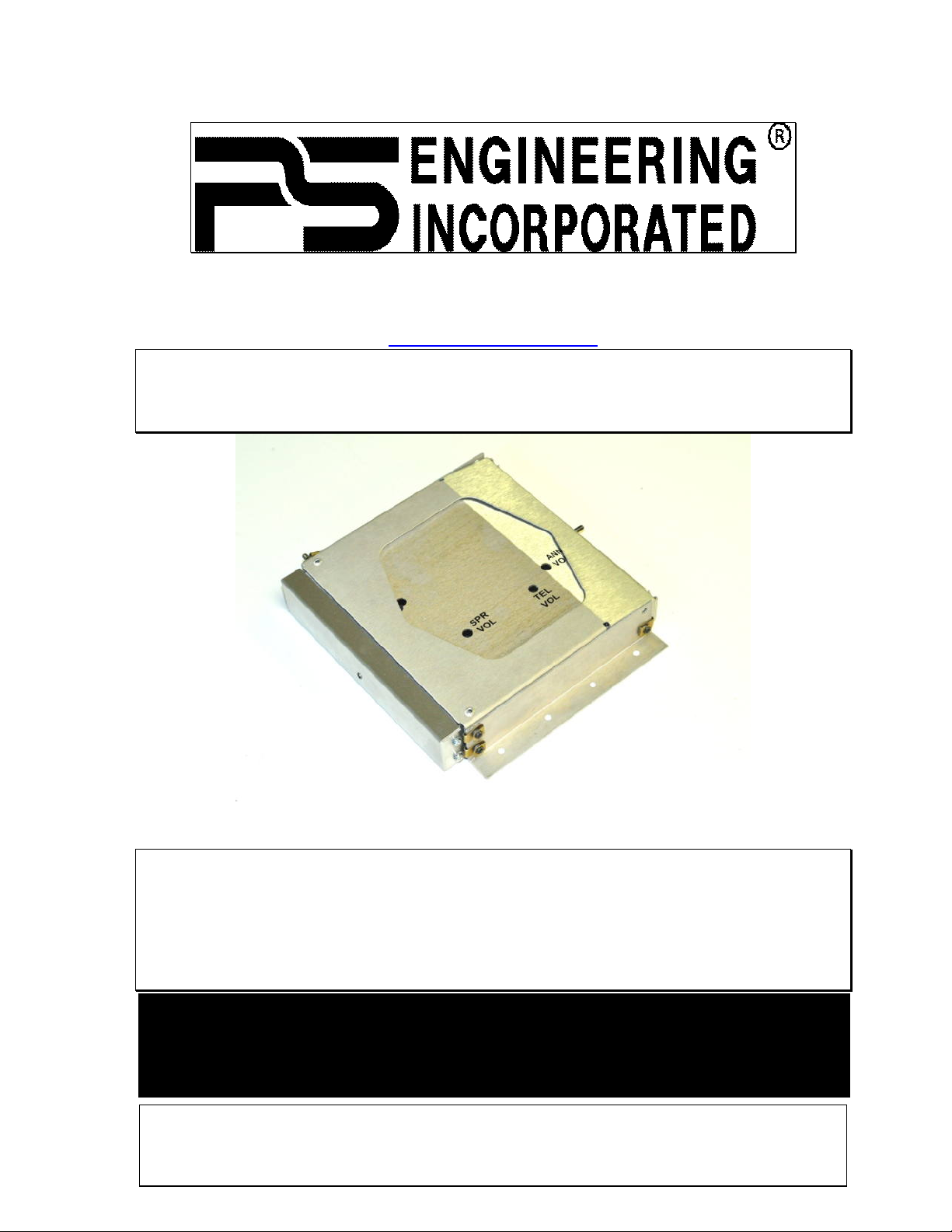
Remote-Mounted Audio Controller with
High-fidelity Stereo Intercom
System Installation and Operation Manual
Patented under one or more of the following;
No. 4,941,187; 5,903,227; 6,160,496 and 6,493,450
PS Engineering, Inc. 2014 ©
Copyright Notice
Any reproduction or retransmittal of this publication, or any portion thereof, without the expressed written permission of PS Engineering, Inc. is strictly prohibited. For further information contact the Publications Manager at PS Engineering, Inc., 9800 Martel
Road, Lenoir City, TN 37772. Phone (865) 988-9800, email contact@ps-engineering.com.
For use in Experimental/LSA/Non-certified aircraft ONLY
Not intended for installation in aircraft with standard airworthiness certification
The product warranty is not valid unless this product is installed by an
Authorized PS Eng
i
neering dealer.
Page 2

Table of Contents
Section I – GENERAL INFORMATION1-1
1.1 INTRODUCTION...................................................................................................................... 1-1
1.2 SCOPE ....................................................................................................................................... 1-1
1.3 EQUIPMENT DESCRIPTION ................................................................................................. 1-1
1.4 APPROVAL BASIS — NONE................................................................................................... 1-1
1.5 SPECIFICATIONS.................................................................................................................... 1-2
1.6 EQUIPMENT SUPPLIED......................................................................................................... 1-2
1.7 EQUIPMENT REQUIRED BUT NOT SUPPLIED.................................................................. 1-3
1.8 LICENSE REQUIREMENTS ................................................................................................... 1-3
Section II - INSTALLATION 2-1
2.1 GENERAL INFORMATION.................................................................................................... 2-1
2.1.1 SCOPE........................................................................................................................ 2-1
2.1.2 CERTIFICATION REQUIREMENTS................................................................................... 2-1
2.2 UNPACKING AND PRELIMINARY INSPECTION............................................................................... 2-1
2.3 EQUIPMENT INSTALLATION PROCEDURES ................................................................................... 2-1
2.3.1 COOLING REQUIREMENTS............................................................................................ 2-1
2.3.2 MOUNTING REQUIREMENTS......................................................................................... 2-1
2.3.3 AUDIO CONTROLLER MOUNTING RACK INSTALLATION................................................ 2-1
2.4 CABLE HARNESS WIRING ............................................................................................................ 2-3
2.4.1 NOISE.......................................................................................................................... 2-3
2.4.2 AUDIO CONTROLLER TRAY AND CONNECTOR ASSEMBLY............................................ 2-4
2.4.3 INPUT POWER .............................................................................................................. 2-4
2.4.4 AUDIO CONTROLLER INTERFACE.................................................................................. 2-4
2.4.5 "SWAP" MODE............................................................................................................. 2-4
2.4.6 UNSWITCHED INPUTS ................................................................................................... 2-4
2.5 INTERCOM WIRING ...................................................................................................................... 2-5
2.5.1 ENTERTAINMENT INPUTS............................................................................................. 2-5
2.5.2 ENTERTAINMENT MUTING............................................................................................ 2-5
2.6 ADJUSTMENTS ............................................................................................................................. 2-6
2.7 MICROPHONE GAIN REDUCTION .................................................................................................. 2-6
2.8 REASSEMBLY............................................................................................................................... 2-7
2.9 COMMUNICATIONS ANTENNA INSTALLATION NOTES .................................................................. 2-9
2.10 PAC15EX PIN ASSIGNMENTS .................................................................................................... 2-9
2.11 POST INSTALLATION CHECKOUT............................................................................................. 2-10
2.12 UNIT INSTALLATION................................................................................................................ 2-10
2.13 OPERATIONAL CHECKOUT ...................................................................................................... 2-10
2.14 FINAL INSPECTION................................................................................................................... 2-11
Page 3

PS Engineering Inc. ®
PAC15EX Audio Selector Panel and Intercom System
Installation and Operator’s Manual
200-015-0000 Page ii Rev. 1, Jan. 2014
Section III OPERATION 3-1
3.1 SCOPE ....................................................................................................................................... 3-1
3.2 POWER AND FAIL SAFE (1)........................................................................................................... 3-1
3.3 COMMUNICATIONS TRANSMIT (XMT) SELECTION (2) ................................................................ 3-1
3.4 COM AUDIO SELECTOR (3) ........................................................................................................ 3-2
3.5 NAVAID AUDIO SELECTION (4)..................................................................................................... 3-2
3.6 INTERCOM OPERATION (8) .......................................................................................................... 3-2
3.6.1 INTELLIVOX® VOX-SQUELCH...................................................................................... 3-2
3.6.2 INTERCOM VOLUME CONTROL (7) ............................................................................... 3-3
3.6.3 INTERCOM MODES (8) ................................................................................................. 3-3
3.7 MUSIC MUTING (9)...................................................................................................................... 3-3
3.7.1 MUSIC 2 MUTE CONTROL............................................................................................ 3-4
Section IV – Warranty and Service 4-1
4.1 WARRANTY ................................................................................................................................. 4-1
4.2 FACTORY SERVICE ...................................................................................................................... 4-1
Appendix B – PAC15EX Installation Drawings .......................................................... A
5.1 REMOTE MOUNTING ......................................................................................................................B
Appendix C – J1 Connector Interconnect A
Appendix D – J2 Connector Interconnect A
Rev Date Change
New October 2012 First Release
1 January 2014 Removed erroneous references
Page 4

PS Engineering Inc. ®
PAC15EX Audio Selector Panel and Intercom System
Installation and Operator’s Manual
200-015-0000 Page 1-1 Rev. 1, Jan. 2014
Section I – GENERAL INFORMATION
1.1 INTRODUCTION
The PAC15EX represents another evolutionary step in cockpit audio control and intercommunications
utility. Using our patented IntelliVox® design and pilot programmable configurations, this marks the next
level of audio control. This unit is designed specifically to be used as remote-mounted audio selector/intercom, controlled by specific integrated avionics suites for experimental aircraft.
Before installing and/or using this product, please read this manual completely. This will ensure that you
will take full advantage of all the advanced features in the PAC15EX.
1.2 SCOPE
This manual provides detailed installation and operation instructions for the PS Engineering PAC15EXseries of Audio Selector Panel/Intercom Systems. This includes the following unit:
Model Description PS Engineering
Part Number
PAC15EX Remote-mounted Audio Selector Panel with stereo intercom. 050-015-0100
1.3 EQUIPMENT DESCRIPTION
The PAC15EX is a state-of-the-art audio isolation amplifier and audio selector that contains an automatic
voice activated (VOX) intercom system and serial data control by a integrated avioncs controller, such as
an MFD. It can switch two transceivers (Com 1, Com 2) and two receivers (Nav 1, Nav 2).
There are four unswitched inputs, available for traffic or EGPWS, autopilot disconnect tones, and/or radar
altimeter warning.
Remote MFD control can select the communication transceivers for the pilot and copilot position, and
allows radio transmission. In "Split Mode" the PAC15EX has the ability to allow the pilot to transmit on
Com 1 while the copilot can transmit on Com 2. A fail-safe mode connects the pilot headphone and microphone to COM 1 if power is removed for any reason, or if the power switch is placed in the Off (Failsafe) position. Unswitched input #1 is also provided to the pilot headphone in fail-safe
A four-station voice activated (VOX) intercom is included in the PAC15EX. This system has PS Engineering’s patented IntelliVox® circuitry that eliminates manual adjustments. The intercom system incorporates pilot isolate, all and crew modes, two independent stereo music inputs with "SoftMute™".
1.4 APPROVAL BASIS — NONE
The PAC15EX is not intended, or approved for installation on US Registered Civilian Aircraft with
normal airworthiness certificates.
Page 5

PS Engineering Inc. ®
PAC15EX Audio Selector Panel and Intercom System
Installation and Operator’s Manual
200-015-0000 Page 1-2 Rev. 1, Jan. 2014
1.5 SPECIFICATIONS
DIMENSIONS: Height: 1.3 in. (3.3 cm) Width: 6.25 in. (16.9 cm)
Depth behind panel 7.15 in. (18.16 cm)
WEIGHT
PAC15EX Unit
Rack with connectors
1.34 lb. (0.61 kg)
0.51 lb. (0.24 kg)
AUDIO CONTROLLER POWER REQUIREMENTS (Including Internal Lighting):
Voltage: 11-33 VDC
Maximum Current: 2.5 Amp (Externally protected by a 3A pull-type
breaker)
Audio Controller Specifications
Audio selector panel input impedance:
510
Input Isolation: -60 dB (min.)
Receiver Inputs: 4 (Com 1, Com 2, Aux 1, Aux 2)
Unswitched Inputs: 4
Transmitter Selections: 3 (Com 1, Com 2,
Com1/2)
Headphone Impedance:
150 – 1000
Headphone Output: 38 mW each headset, no clipping <1% THD typi-
cal into 150
Microphone Impedance:
150 - 600
Intercom Specifications
Intercom Positions: 4 places (with individual IntelliVox® circuits)
Music Inputs:
2, (Independent, Stereo)
Music Muting:
>-30 dB "Soft Mute" when Com or intercom active.
Distortion:
<1% THD @ 38 mW into 150
Mic Freq. Response, 3 dB:
300 Hz - 6000 Hz
Music Freq. Response, 3 dB:
10 Hz – 26 kHz
1.6 EQUIPMENT SUPPLIED
1 ea. of the following items:
Model Description Part Number
PAC15EX PAC15EX Remote-mounted Audio Controller with intercom 050-015-0100
Installation Kit: 250-015-0000, containing:
Description Quantity Part Number
PAC15EX installation rack assembly 1 430-890-0040
PAC15EX Rack back plate 1 430-890-0050
44-pin connector kit 2 120-891-2045
Backshell, connector 2 625-025-2465
Backshell Retainer 2 431-891-0100
4 40 X 7/16 screw w/nylon patch 4 475-440-0007
4 40 X 3/8 screw w/lock washer 4 475-440-1038
4 40 X 1/8 screw w/lock washer 2 475-440-0001
Solder Lug 2 475-009-0001
Cable Clamp 1 625-001-0002
#6-32 x ½” Flat head Philips screw 6 475-632-0012
#6-32 Clip Nut 6 475-630-0002
PAC15EX Horizontal Mounting Flange 2 430-200-0042
PAC15EX Vertical Mounting Bracket 1 430-200-0070
Page 6

PS Engineering Inc. ®
PAC15EX Audio Selector Panel and Intercom System
Installation and Operator’s Manual
200-015-0000 Page 1-3 Rev. 1, Jan. 2014
1.7 EQUIPMENT REQUIRED BUT NOT SUPPLIED
a. Circuit Breaker: 1 ea; 3 amp PULL TYPE REQUIRED for PAC15EX
b. Headphone Jacks (up to 4 Stereo, as Required)
c. Microphone Jacks (up to 4 as Required)
d. Headphones, 150 (Stereo), up to 4 as required
e. Microphones, up to 4 as required
f. Interconnect Wiring, coaxial cable
1.8 LICENSE REQUIREMENTS
None.
Page 7

PS Engineering Inc. ®
PAC15EX Audio Selector Panel and Intercom System
Installation and Operator’s Manual
200-015-0000 Page 2-1 Rev. 1, Jan. 2014
Section II - INSTALLATION
2.1 GENERAL INFORMATION
2.1.1 SCOPE
This section provides detailed installation and interconnection instructions for the PS Engineering
PAC15EX Audio Controller with Intercom.
Please read this manual carefully before beginning any installation to prevent damage and postinstallation problems. Installation of this equipment requires special tools and knowledge.
2.1.2 Certification Requirements
NOTE
The PAC15EX is not approved for installation in aircraft with a standard airworthiness certificate.
2.2 Unpacking and Preliminary Inspection
Use care when unpacking the equipment. Inspect the units and parts supplied for visible signs of shipping
damage. Examine the unit for loose or broken buttons, bent knobs, etc. Verify the correct quantity of
components supplied with the list in Section 1.6 (B). If any claim is to be made, save the shipping material and contact the freight carrier. Do NOT return units damaged in shipping to PS Engineering. If the
unit or accessories show any sign of external shipping damage, contact PS Engineering to arrange for a
replacement. Under no circumstances attempt to install a damaged unit in an aircraft. Equipment returned
to PS Engineering for any other reason should be shipped in the original PS Engineering packaging, or
other UPS approved packaging.
2.3 Equipment Installation Procedures
2.3.1 Cooling Requirements
Forced air-cooling of the PAC15EX is not required. However, the units should be kept away from heat
producing sources (i.e. defrost or heater ducts, dropping resistors, heat producing avionics) without adequate cooling air provided.
2.3.2 Mounting Requirements
The PAC15EX must be rigidly mounted to the aircraft structure, The unit may be mounted in any area
where adequate clearance for the unit and associated wiring bundle exist.
To prevent noise, avoid installing the unit close to high current devices or systems with high-voltage pulse
type outputs, such as DME or transponders. Avoid running the interconnecting bundles near any high
current wires.
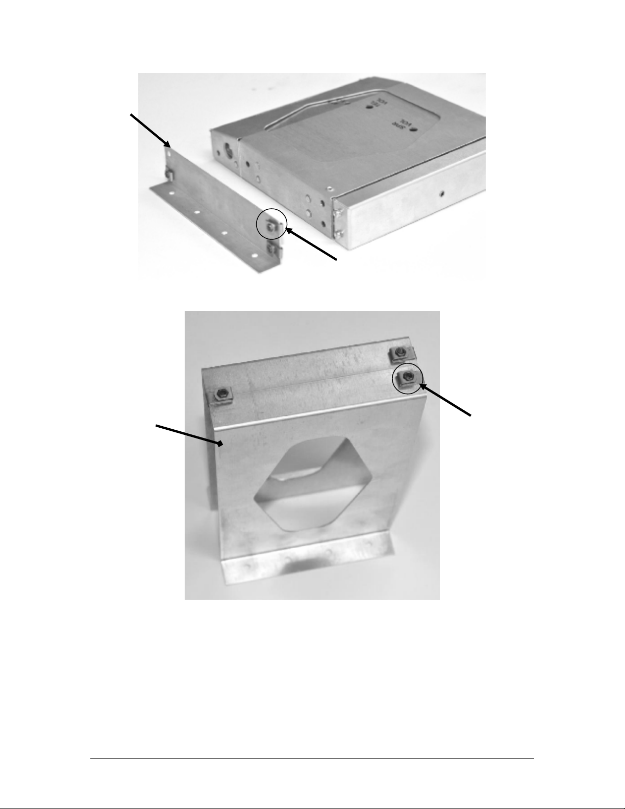
2.3.3 Audio Controller Mounting Rack Installation
Remove the unit from the mounting tray by unscrewing the 3/32" hex-head screw that is in the center of
the unit. Carefully slide the unit free of the tray. Set the unit aside in a safe location until needed.
The unit can be installed horizontally, with two mounting flanges (430-200-0042), six #6-32 clip nuts
(475-630-0002), and six FHP 6-32 x ½" screws (475-632-0012). to attach the tray to the flanges with the
screw head on the inside of the tray.
Page 8
PS Engineering Inc. ®
PAC15EX Audio Selector Panel and Intercom System
Installation and Operator’s Manual
200-015-0000 Page 2-2 Rev. 1, Jan. 2014
Figure 2-1 Horizontal Mounting Flanges
Figure 2-2 Vertical Mounting Bracket
430-200-0042 (x2)
475-630-0002 (x6)
Unit & Tray
430-200-0070
475-630-0002 (x3)
Page 9
PS Engineering Inc. ®
PAC15EX Audio Selector Panel and Intercom System
Installation and Operator’s Manual
200-015-0000 Page 2-3 Rev. 1, Jan. 2014
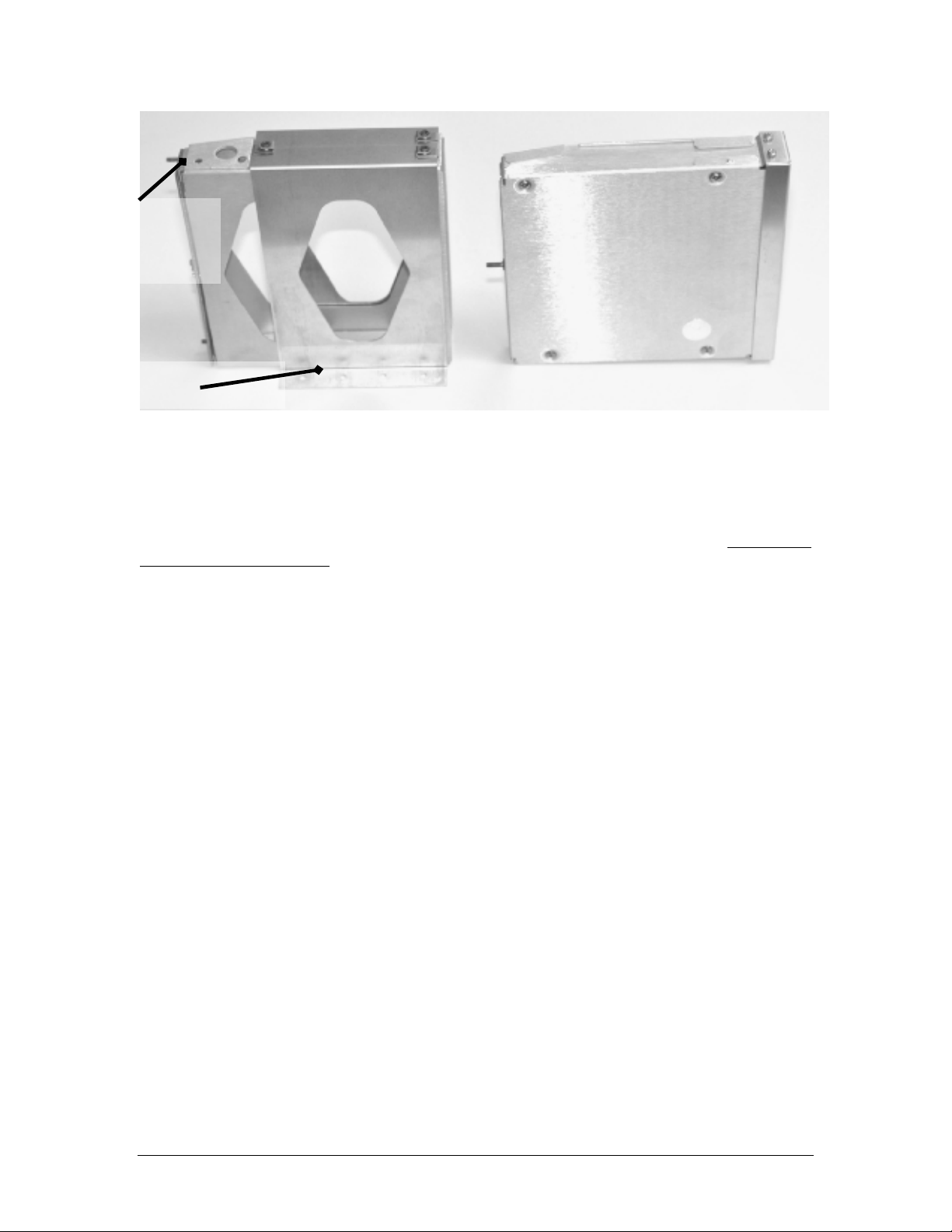
The flanges can then be attached to the aircraft structure as appropriate. Refer to FAA AC 43.13-2B,
Chapter 1 and 2 for more information.
2.4 Cable Harness Wiring
Referring to the appropriate Appendix, assemble a wiring harness as required for the installation. All
wires must be MIL-SPEC in accordance with current regulations. Two- and three-conductor shielded wire
must be used where indicated, and be MIL-C-27500 or equivalent specification. Proper stripping, shielding and soldering technique must be used at all times. It is imperative that correct wire be used.
Refer to FAA Advisory Circular 43.13-2B for more information. Failure to use correct techniques may
result in improper operation, electrical noise or unit failure. Damage caused by improper installation will
void the PS Engineering warranty.
2.4.1 Noise
Due to the variety and the high power of radio equipment often found in today's general aviation aircraft,
there is a potential for both radiated and conducted noise interference.
The PAC15EX power supply is specifically designed to reduce conducted electrical noise on the aircraft
power bus by at least 50dB. Although this is a large amount of attenuation, it may not eliminate all noise,
particularly if the amplitude of noise is very high. There must be at least 13.8 VDC present at the connector, J2 pins 8 & 9, of the PAC15EX for the power supply to work in its designed regulation. Otherwise, it
cannot adequately attenuate power line noise. Shielding can reduce or prevent radiated noise (i.e., beacon,
electric gyros, switching power supplies, etc.) However, installation combinations can occur where interference is possible. The PAC15EX was designed in a RFI hardened chassis and has internal Electromagnetic Interference (EMI) filters on all inputs and outputs.
Ground loop noise occurs when there are two or more ground paths for the same signal (i.e., airframe and
ground return wire). Large cyclic loads such as strobes, inverters, etc., can inject noise signals onto the
airframe that are detected by the audio system. Follow the wiring diagram very carefully to help ensure a
minimum of ground loop potential. Use only Mil Spec shielded wires (MIL-C-275000, or better). Under
no circumstances combine a microphone and headphone wiring into the same shielded bundle. Always
use a 2- or 3-conductor, shield wire as shown on the installation-wiring diagram.
The shields can be daisy-chained together, and then connected to the ground lugs mounted on the center
of the back plate.
Radiated signals can be a factor when low level microphone signals are "bundled" with current carrying
power wires. Keep these cables physically separated. It is very important that you use insulated washers to
isolate the ground return path from the airframe to all headphone and microphone jacks.
430-200-0070
Vertical Mounting Bracket
PAC15EX Unit
430-890-0040
Tray &
430-890-0050
Back Plate
Page 10

PS Engineering Inc. ®
PAC15EX Audio Selector Panel and Intercom System
Installation and Operator’s Manual
200-015-0000 Page 2-4 Rev. 1, Jan. 2014
2.4.1.1 Music Inputs and Noise
If a music jack is installed for Music 1 or 2, we strongly recommend isolating the jack from airframe
ground, by using an insulated mounting plate.
NOTE
Adding a high-performance audio control system, particularly in conjunction with high-performance active noise canceling headsets, cannot improve on older avionics that were designed for cabin-speaker use.
PS Engineering makes no claim that the Audio Controller will provide a noise-free audio quality under all
installation conditions, particularly with older avionics.
2.4.2 Audio Controller Tray and Connector Assembly
The rack connectors mate with two 44-pin connectors in the PAC15EX. The connectors are a subminiature crimp-type, and require the use a hand crimp tool, from table below (or equiv.). The connectors
are mounted to the tray back plate with #4-40 screws (475-440-1038), from the inside of the tray and the
mounting block, 431-891-0100. Ensure that proper strain relief and chafing precautions are made during
wiring and installation, using the cable clamp (625-001-0002).
Manufacturer Crimping Tool Positioner Extraction tool
AMP 601966-1 601966-6 91067-1
Daniels AFM8 K42 M24308-1
ITT-Cannon 995-0001-584 995-0001-739 91067-1
Table 2-1 PAC15EX Connector Pin crimping tools
2.4.3 Input Power
The PAC15EX is compatible with both 14 and 28 Volt DC systems. A three (3) Amp circuit breaker is
required for all installations. Power and ground wires should be #22 connected to J2 Pins 8 and 9. Connect airframe ground to J2 Pin 10 and 11 only. No dropping resistors are required.
2.4.4 Audio Controller interface
The PAC15EX is designed to interface with standard aircraft avionics, and presents a 510 receiver impedance. For best results, a twisted-shielded cable is recommended from the avionics audio source to the
Audio Controller, with the shield grounded at the Audio Controller end.
Inputs A1 and A2 can be used to control navigation receiver audio, J1 Pins 17 WRT 18 and J1 19 WRT
20, respectively.
Some avionics do not provide a separate audio low, and may introduce additional electrical noise into the
system. For best results, connect the audio low from the Audio Controller to the radio ground, using one
conductor of the twisted-shielded cable.
2.4.5 "Swap" Mode
When a momentary, normally open, push-button switch is connected between pin 20 on the J2 connector
and aircraft ground, the user can switch between Com 1 and 2 by depressing this switch without having to
turn the mic selector switch. This yoke-mounted switch eliminates the need to remove your hands from
the yoke to change transceivers.
2.4.6 Unswitched inputs
J1, pins 31, 29 and J2 pin 15 are unswitched, unmuted (by transmitter keying), inputs # 1, 3 and 4, respectively. These inputs are presented to the pilot and copilot regardless of the audio configuration, and
will mute the entertainment inputs based on the mode. These 510 Ω inputs can be used for altimeter DH
audio, GPS waypoint audio, autopilot disconnect tones, or any other critical audio signal. Unswitched #1
Page 11

PS Engineering Inc. ®
PAC15EX Audio Selector Panel and Intercom System
Installation and Operator’s Manual
200-015-0000 Page 2-5 Rev. 1, Jan. 2014
is always presented to the crew headphones, and is available to the pilot in fail-safe (off) mode.
Unswitched 3 and 4 inputs are always presented to the crew headphones.
Unswitched
Input
Input
Pin
Hear in
Fail Safe
Hear in
Crew Headset
Gain
1 J1, 31 Yes Yes 1:1(fixed)
2 J1, 44 No Yes 1:1(fixed)
3 J1, 29 No Yes Adjustable
4 J2, 15 No Yes 1:1(fixed)
Table 2-2 Unswitched input table
The audio low for unswitched #4 (J2, pin 15) should be connected to a convenient audio low such as J2,
Pin 40. However, this should NOT be connected to Music Low (J2 pin 36 or 38).
Unswitched #1 (J1 Pins 31 & 32) is presented to the pilot headphone in fail-safe (off) mode.
NOTE
Inputs 1, 2 and 4 are fixed (1:1), and any audio level adjustments must be made at the input source. Unswitched #3
has a variable adjustment control located on the bottom side of the unit. This control allows you to control the volume
level of that unswitched input from 50% to 200% of the input level. Refer to Adjustments section.
2.5 Intercom wiring
See Appendix C and D for intercom connection configurations. It is critical to the proper operation of this
system to have this connector wiring made in accordance with these diagrams. Use 2- and 3-conductor,
MIL-spec cable as shown. Connect the shields at the Audio Controller end only, and tie to the audio low
inputs as shown.
NOTE
The system harness can be custom made by PS Engineering, Inc. Simply call the factory or www.ps-
engineering.com to obtain a wire harness work sheet. The harness will be made to your specifications and
fully functionally tested. Harness can be ordered with jack, or without the intercom jacks installed, for
easier wire routing through the aircraft.
2.5.1 Entertainment Inputs
The PAC15EX has two INDEPENDENT inputs wired into the rear connectors. Entertainment input number 1 is J2 pins 23 (left channel) and 24 (right channel), with respect to pin 25, and Entertainment number 2 is connected to 26 (left channel), 27 (right channel), with respect to 28.
NO T E
Us e th e low l evel ou tp ut of an y a ddi tion al en ter tai nme n t d ev i ce to con nec t to th e A udi o Con t rol le r. Max i mum sig nal le v e l i s 3 V AC p- p . D O NO T use a s p ea ker - level
out p ut, th is w i ll ca use i nt er na l d a mag e in th e A u di o Con t rol le r.
2.5.2 Entertainment muting
The PAC15EX-system incorporates a "Soft Mute™" system. This will mute the entertainment devices
during ICS or radio conversation. The four muting modes are controlled by the MFD. See §3.7 for more
information.
CAUTION
Local oscillators and internal signals from entertainment equipment can cause undesired interference with
other aircraft systems. Before takeoff, operate the entertainment devices to determine if there is any adverse effect within the aircraft systems. If any unusual operation is noted in flight, immediately switch off
the entertainment devices.
All entertainment devices must be switched off for both takeoff and landing.
Page 12

PS Engineering Inc. ®
PAC15EX Audio Selector Panel and Intercom System
Installation and Operator’s Manual
200-015-0000 Page 2-6 Rev. 1, Jan. 2014
2.5.2.1 Entertainment 2 Mute (J2 Pin 13 & 14)
Connecting J2 pin 13 to pin 14 (or ground) through a SPST switch places the entertainment #2 music
source into the Karaoke Mode. In this mode, incoming music and intercom conversation will not mute the
music for the passengers’ intercom net. This allows uninterrupted music during casual conversation and
at times when radio communications are of lesser importance.
2.6 Adjustments
The PAC15EX is factory adjusted to accommodate the typical requirements for most aircraft configurations. There are three adjustments in the top cover that allow the installer to tailor the specific functions.
Unswitched Input 3 Volume, adjust from 50% to 200% of input value. (Bottom cover must be
removed).
Figure 2-3 – PAC15EX DIP Switches
2.7 Microphone gain reduction
For installations in very noisy aircraft, a reduction in the intercom microphone input gain may be desirable. The PAC15EX has two DIP switches located on the main board that can switch the inputs to a lower
gain setting.
Remove the top cover (see above), and locate the two DIP switches near the mounting rod at the rear of
the unit.
NOTE:
If top cover is removed
for ANY reason, you
MUST replace the cover
screws with the proper
length, otherwise damage
will result.
Shorter Screw
DIP Switches
Unswitched 3
Page 13

PS Engineering Inc. ®
PAC15EX Audio Selector Panel and Intercom System
Installation and Operator’s Manual
200-015-0000 Page 2-7 Rev. 1, Jan. 2014
Figure 2-4 DIP switches
Change the settings as shown in the table below.
Switch Noisy Cockpit Normal Cockpit Switch Bank
Pilot Microphone
1 OFF ON
2 ON OFF
Copilot Microphone
3 OFF ON
J5
4 ON OFF
Passenger 1 Microphone
1 OFF ON
2 ON OFF
Passenger 2 Microphone
3 OFF ON
J4
4 ON OFF
Table 2-3 Microphone gain settings
Carefully reassemble the unit.
2.8 Reassembly
1. Using the nylon spacers removed in step 2, compress them so it they becomes ob-
long.
1
2
3
4
5
6
ON
OFF
ON
OFF
Page 14

PS Engineering Inc. ®
PAC15EX Audio Selector Panel and Intercom System
Installation and Operator’s Manual
200-015-0000 Page 2-8 Rev. 1, Jan. 2014
Figure #3
a. Install one long screw through the top lid, near the front edge on the power
supply board side, and add then add the nylon spacers from § 2.8.
Figure #4
4. Place the lid back on the unit aligning holes.
5. Install qty. 2 more long thread screws into the lid.
Page 15

PS Engineering Inc. ®
PAC15EX Audio Selector Panel and Intercom System
Installation and Operator’s Manual
200-015-0000 Page 2-9 Rev. 1, Jan. 2014
6. Install qty. 1 short thread screw to the rear of the unit.
2.9 Communications Antenna Installation Notes
For best results while in Split Mode, it is recommended that the one VHF communications antenna is located on top of the aircraft while the other communications antenna is installed on the bottom. Any antenna relocation should be accomplished in accordance with AC 43.13-2B, and /or aircraft manufacturers’
recommendations.
WARNING
It is probable that radio interference will occur in the split mode when the frequencies of the two aircraft radios are adjacent, and/or the antennas are physically close together. PS Engineering makes
no expressed or implied warranties regarding the suitability of the PAC15EX in Split Mode.
2.10 PAC15EX Pin assignments
J1 Function J2 Function
1 No Connect 1 Pilot Phones Lo
2 No Connect 2 Copilot Phones Lo
3 No Connect 3 Copilot Phones (L)
4 No Connect 4 Copilot Phones (R)
5 No Connect 5 No Connect
6 No Connect 6 No Connect
7 No Connect 7 No Connect
8 No Connect 8 Aircraft Power
9 Com 1 Audio 9 Aircraft Power
10 Com 1 Audio Lo 10 Aircraft Ground
11 Com 1 Mic 11 Aircraft Ground
12 Com 1 Mic Key 12 No Connect
13 Com 2 Audio 13 Music 2 Mute Inhibit
14 Com 2 Audio Lo 14 Music 2 Mute Inhibit Lo
15 Com 2 Mic 15 Unswitched #4
16 No connect 16 Pilot Phones (L)
17 Aux 1 Audio 17 RS232 RXD
18 Aux 1 Audio Lo 18 No connect
19 Aux 2 Audio 19 No connect
20 Aux 2 Audio Lo 20 Swap
Page 16

PS Engineering Inc. ®
PAC15EX Audio Selector Panel and Intercom System
Installation and Operator’s Manual
200-015-0000 Page 2-10 Rev. 1, Jan. 2014
J1 Function J2 Function
21 No Connect 21 No connect
22 Unswitched #3 Lo 22 Music 1 All Headsets
23 No Connect 23 Music 1 (L)
24 No Connect 24 Music 1 (R)
25 No Connect 25 Music 1 Lo
26 No Connect 26 Music 2 (L)
27 No Connect 27 Music 2 (R)
28 No Connect 28 Music 2 Lo
29 Unswitched #3 29 RS232 TX
30 Com 2 Mic Key 30 No Connect
31 Unswitched Audio 1 31 Pilot Phones (Rt)
32 Unswitched Lo 32 Copilot Mic Audio
33 Pilot Mic Audio 33 Copilot Mic PTT
34 Pilot Mic PTT 34 Copilot Mic Lo
35 Pilot Mic Lo 35 Pass 1 Mic Audio
36 No Connect 36 Pass 1 Mic Audio Lo
37 No Connect 37 Pass 2 Mic Audio
38 No Connect 38 Pass 2 Mic Audio Lo
39 No Connect 39 No Connect
40 Pass HP (L) 40 Unswitched #4 Lo
41 Pass HP (R) 41 No Connect
42 Pass HP Lo 42 No Connect
43 Unswitched 2 Lo 43 No Connect
44 Unswitched 2 Audio 44 No Connect
2.11 Post Installation Checkout
After wiring is complete, verify power is ONLY on pins 8, and 9 of the J2 and airframe ground on connector pins 10, and 11. Failure to do so will cause serious internal damage and void PS Engineering's
warranty.
2.12 Unit Installation
To install the PAC15EX, gently slide the unit into the mounting rack until the hold-down screw is engaged. While applying gentle pressure to the face of the unit, tighten the 3/32" hex-head in the center of
the unit until it is secure. DO NOT OVER TIGHTEN.
CAUTION
Apply steady pressure to the front while screwing the unit into the tray to ensure even seating of the unit
and connectors.
WARNING
Do not over-tighten the lock down screw while installing the unit in tray. Internal damage will result.
2.13 Operational Checkout
NOTE
The IntelliVox® is designed for ambient noise levels of 80 dB or above. Therefore some clipping may occur in a quiet cabin, such as without the engine running, in a hangar. This is normal.
1. Apply power to the aircraft and avionics.
2. Plug headsets into the pilot, copilot, and occupied passenger positions.
Page 17

PS Engineering Inc. ®
PAC15EX Audio Selector Panel and Intercom System
Installation and Operator’s Manual
200-015-0000 Page 2-11 Rev. 1, Jan. 2014
3. Verify fail-safe operation by receiving and transmitting on com 1 from the pilot position, with the
Audio Controller power off. The Com and Unswitched #1 audio will be present in one ear cup only.
4. Apply power to the unit.
5. Check intercom operation.
6. Select COM 1 for transmitting on the MFD.
7. Verify proper transmit and receive operation from the copilot position, noting that the copilot PTT
switch allows proper transmission on the selected transceiver.
8. Verify that the Com 2 receiver to be selected and heard. Verify operation on Com 1 from the pilot
position.
9. Repeat for Com 2
10. Verify that the split mode can be invoked from the MFD, and verify that the pilot can transmit and
receive on Com 1, while the copilot transmits and receives on Com 2.
11. Verify proper operation of all receiver sources by selecting them using the appropriate means. The A1
and A2 indicators illuminate to show which navigation audio source is in use.
12. Verify that the appropriate transmit indicator is active when either push to talk is keyed.
13. Verify proper Intercom system operation in the ALL, ISO and CREW modes (see Table 3-1).
14. Verify that the audio selector panel system does not adversely affect any other aircraft system by sys-
tematically switching the unit on and off, while monitoring the other avionics and electrical equipment on the aircraft.
2.14 Final Inspection
Verify that the wiring is bundled away from all controls and no part of the installation interferes with aircraft control operation. Move all controls through their full range while examining the installation to see
that no mechanical interference exists. Verify that the cables are secured to the aircraft structure in accordance with good practices, with adequate strain relief. Ensure that there are no kinks or sharp bends in the
cables and coaxial cables. Verify that the cables are not exposed to any sharp edges or rough surfaces, and
that all contact points are protected from abrasion.
Return completed warranty registration application to PS Engineering, or complete online at www.psengineering.com.
Page 18

PS Engineering Inc. ®
PAC15EX Audio Selector Panel and Intercom System
Installation and Operator’s Manual
200-015-0000 Page 3-1 Rev. 1, Jan. 2014
Section III OPERATION
3.1 SCOPE
This section provides detailed operating instructions for the PS Engineering PAC15EX, Audio Controller
Systems. Please read it carefully before using the equipment so that you can take full advantage of its capabilities.
This section is divided into sections covering the basic operating areas of the PAC15EX systems. They are
Communications Transceiver Selection, Audio Selector, Intercom, and entertainment.
Operation is completely dependent on the specific display that the PAC15EX is interfaced with. Please
refer to the operating guide for your installation.
3.2 Power and Fail Safe (1)
When power is not applied to the Audio Controller, the pilot headset is connected directly to Com 1 as
well as unswitched input #1. This allows communication capability regardless of unit condition. Any time
power is removed or turned OFF, the audio selector portion will revert to fail-safe mode.
The power switch controls all audio selector panel functions and the intercom. All pushbutton selections
and menu modes will be remembered and return to the last state when turned on.
3.3 Communications Transmit (XMT) Selection (2)
The microphone selector section of the MFD controls which communications radio is selected for transmit. The receiver controls allows selection of the receiver audio.
The PAC15EX-Series has an automatic com receiver selector system. Audio from the selected transceiver
is automatically heard in the headsets and speaker (if selected). This guarantees that the pilot will always
hear the audio from the transceiver selected for transmit.
The PAC15EX “remembers” the receiver selection, so that when switching transmitters from COM 1 to
COM 2, if COM 2 audio was previously selected, COM 1 audio will continue to be heard. This eliminates
the pilot having to switch Com 1 audio back on, after changing transmitters.
When switching from COM 1 to COM 2 while Com 2 was not previously selected, COM 1 audio will be
switched off. In essence, switching the mic selector will not override prior selection of COM receiver audio.
In normal (not split) modes, the PAC15EX gives priority to the pilot’s radio Push-To-Talk (PTT). If the
copilot it transmitting, and the pilot presses his PTT, the pilot’s microphone will be heard over the selected com transmitter.
3.3.1.1 Split Mode
The split mode can be selected at any time on the MFD. This places the pilot on COM 1 and the Copilot on
COM 2.
Pilot on COM 2 and Copilot on COM 1 is not possible.
NO T E
Due to the nature of VHF communications signals, and the size constraints in general aviation aircraft, it
is probable that there will be some bleed-over in the Split mode, particularly on adjacent frequencies. PS
Engineering makes no warranty about the suitability of Split Mode in all aircraft conditions.
3.3.1.2 Swap Mode (Switch from Com 1 to Com 2 remotely)
With a yoke mounted, normally open momentary switch, the pilot can change from the current Com
transceiver to the other by depressing this switch. To cancel "Swap Mode," the pilot may either press the
Page 19

PS Engineering Inc. ®
PAC15EX Audio Selector Panel and Intercom System
Installation and Operator’s Manual
200-015-0000 Page 3-2 Rev. 1, Jan. 2014
yoke mounted switch again, or select a different Com with the XMT buttons.
3.4 COM Audio Selector (3)
Communication audio from the other radio, not selected for transmit, can be heard by pressing the associated button. You will always hear the audio from the selected transceiver.
In SPLIT mode, only the pilot will hear selected navigation audio (A1 & A2).
3.5 Navaid Audio selection (4)
VHF Navigation receiver audio is selected through receiver control functions.
The MKR (Marker), ADF AUX (auxiliary) and DME audio is interfaced through an unswitched input.
3.6 Intercom Operation (8)
3.6.1 IntelliVox® VOX-Squelch
No manual adjustment of the IntelliVox® squelch control is possible. Through individual signal processors, the ambient noise appearing in all four microphones is constantly being sampled. Non-voice signals
are blocked. When someone speaks, only their microphone circuit opens, placing their voice on the intercom. The intercom can be configured for high noise environment by internal switching. See § 2.7 for
more information.
The system is designed to block continuous tones; therefore people humming or whistling in monotone
may be blocked after a few moments.
For consistent performance, any headset microphone must be placed within ¼-inch of your lips, preferably against them. (ref: RTCA/DO-214, 1.3.1.1 (a)).
NOTE
It is also a good idea to keep the microphone out of a direct wind path. Moving your head through a vent
air stream may cause the IntelliVox® to open momentarily. This is normal.
The IntelliVox® is designed to work with normal aircraft cabin noise levels (70 dB and above). It loves
airplane noise! Therefore, it may not recognize speech and clip syllables in a quiet cabin, such as in the
hangar, or without the engine running. This is normal.
For optimum microphone performance, PS Engineering recommends installation of a Microphone Muff
Kit from Oregon Aero (1-800-888-6910). This will not only optimize VOX performance, but will improve
the overall clarity of all your communications.
Table 3-1 Mic Muff ™ Part Numbers
Manufacturer Model Mic Muff™ Part Number
Bose Dynamic
Electret
M87 Dynamic
90010
90015
90020
David Clark H10-30
H10-20, H10-40
H10-13.4
90010
90015
90015
Lightspeed All 90015
Peltor 7003
7004
90010
90015
Pilot 11-20 & 11-90 90015
Sennheiser 90015
Telex Airman 750, Echelon
AIR3000
90015
90010
Page 20

PS Engineering Inc. ®
PAC15EX Audio Selector Panel and Intercom System
Installation and Operator’s Manual
200-015-0000 Page 3-3 Rev. 1, Jan. 2014
3.6.2 Intercom Volume Control (7)
The single volume control slider on the MFD adjusts the loudness of the intercom for the pilot, copilot,
and passengers. It has no effect on selected radio or music input levels.
Adjust the radios and intercom volume for a comfortable listening level. Most general aviation headsets
today have built-in volume controls; therefore, volume also can be further adjusted at the individual headset.
3.6.2.1 Mono headsets in Stereo Installation
The pilot and copilot positions work with stereo or mono headsets. All passenger headsets are connected
in parallel. Therefore, if a monaural headset is plugged in to a PAC15EX Stereo installation, one channel
will be shorted. Although no damage to the unit will occur, passengers with stereo headsets will only hear
in one ear, unless they switch to the “MONO” mode on their headset.
3.6.3 Intercom Modes (8)
The “ICS” control provides the selection of the three intercom modes.
ISO: The pilot is isolated from the intercom and is connected only to the aircraft radio system. He will
hear the aircraft radio reception (and sidetone during radio transmissions). Copilot will hear passengers’
intercom and entertainment, while passengers will hear copilot intercom and entertainment. Neither will
hear aircraft radio receptions or pilot transmissions.
When the Audio Controller is put into the “Split Mode” (pilot on COM 1, copilot on COM 2), the mute
control becomes active. Toggle the mute control, and the intercom becomes active again. The intercom
can be changed to the CRW or ALL mode if desired.
ALL: All parties will hear the aircraft radio and intercom. Crew and passengers will hear selected entertainment. During any radio or intercom communications, the music volume automatically decreases. The
music volume increases gradually back to the original level after communications have been completed.
CREW: Pilot and copilot are connected on one intercom channel and have exclusive access to the aircraft
radios. They may also listen to Entertainment 1. Passengers can continue to communicate with themselves
without interrupting the Crew and may listen to entertainment as configured.
3.7 Music Muting (9)
There are two SoftMute™ muting circuits. The crew "Mute" control has four modes, and controls the
Mute function for music 1. Music 2 muting is controlled by an external switch, and has two modes.
The SoftMute™ circuit will cut the music out whenever there is conversation on the radio, the intercom,
or both, depending on the “Mute” mode selected. When that conversation stops, the music returns to the
previous level comfortably, over a second or so.
The mute mode functions are controlled through the Mute command.
MUTE ON - music will mute with either intercom or radio – MUTE ON button is lit.
RADIO MUTE – Intercom will not mute music, radio will mute music. RAD LED indicator is on
INTERCOM MUTE - Radio will not mute music, intercom will mute music - MUTE ICS LED is
ON.
MUTE OFF - “Karaoke” mode - music will not mute except during outgoing transmissions.- All Indicators off.
♫ Music
Intercom Radio INDICATOR
Mute ON Muted Muted ON
Mute OFF ♫ ♫ None
Page 21

PS Engineering Inc. ®
PAC15EX Audio Selector Panel and Intercom System
Installation and Operator’s Manual
200-015-0000 Page 3-4 Rev. 1, Jan. 2014
Radio Mute ♫ Muted RAD
ICS Mute Muted ♫ ICS
The passenger’s intercom also has a SoftMute™ circuit. If the passengers hear the radio, or talk on
the intercom, the music will mute. If the Audio Controller is in CREW mode, then the radio reception will not affect the passenger music.
3.7.1 Music 2 Mute Control
Passengers also have a Karaoke Mode. If the passengers are listening to the music 1 input their
Karaoke Mode is controlled by the crew “Mute” control. If the passengers are listening to the music 2 input, their Karaoke Mode is activated by an external switch.
Page 22

PS Engineering Inc. ®
PAC15EX Audio Selector Panel and Intercom System
Installation and Operator’s Manual
200-015-0000 Page 4-1 Rev. 1, Jan. 2014
Section IV – Warranty and Service
4.1 Warranty
In order for the factory warranty to be valid, the installations must be accomplished under the supervision of an authorized PS Engineering dealer. If the unit is being installed by a non-certified individual in an experimental aircraft, a PS Engineering authorized dealer, or factory-made intercom harness must be used for the warranty to be valid.
PS Engineering, Inc. warrants this product to be free from defect in material and workmanship for a
period of two (2) years from the date of sale. During the two-year warranty period, PS Engineering, Inc.,
at its option, will send a replacement unit at our expense if the unit should be determined to be defective
after consultation with a factory technician.
All transportation charges for returning the defective units are the responsibility of the purchaser. All domestic transportation charges for returning the exchange or repaired unit to the purchaser will be borne by
PS Engineering, Inc. The risk of loss or damage to the product is borne by the party making the shipment,
unless the purchaser requests a specific method of shipment. In this case, the purchaser assumes the risk
of loss.
This warranty is not transferable. Any implied warranties expire at the expiration date of this warranty.
PS Engineering SHALL NOT BE LIABLE FOR INCIDENTAL OR CONSEQUENTIAL DAMAGES.
This warranty does not cover a defect that has resulted from improper handling, storage or preservation,
or unreasonable use or maintenance as determined by us. This warranty is void if there is any attempt to
dissemble this product without factory authorization. This warranty gives you specific legal rights, and
you may also have other rights, which may vary from state to state. Some states do not allow the exclusion
of limitation of incidental or consequential damages, so the above limitation or exclusions may not apply
to you.
All items repaired or replaced under this warranty are warranted for the remainder of the original warranty period. PS Engineering, Inc. reserves the rights to make modifications or improvements to the product without obligation to perform like modifications or improvements to previously manufactured products.
4.2 Factory Service
The units are covered by a two-year limited warranty. See warranty information. Call PS Engineering,
Inc. at (865) 988-9800 before you return any unit. This will allow the service technician to provide any
other suggestions for identifying the problem and recommend possible solutions.
After discussing the problem with the technician and you obtain a Return Authorization Number, ship
product to:
PS Engineering, Inc.
Attn: Service Department
9800 Martel Rd
Lenoir City, TN 37772
(865) 988-9800 FAX (865) 988-6619
Email: support@ps-engineering.com
Units that arrive without an RMA number, or telephone number for a responsible contact, will be
returned un-repaired. PS Engineering is not responsible for items sent via US Mail.
Page 23

PS Engineering Inc. ®
PAC15EX Audio Selector Panel and Intercom System
Installation and Operator’s Manual
200-015-0000 Appendix C Rev. 1, Jan. 2014
Appendix B – PAC15EX Installation Drawings
J2 J1
Viewed from Back
15
30
44
1
16
31
15
30
44
1
16
31
Ground Lug
Ground Lug
475-440-0001 (x2)
Back plate as sy
475-009-0001
ground lug (x2)
475-440-0001 (x2)
Screw w/washer
Ground lug detail
Rear plate detail (not to scale)
Caut i on : A p pl y st ea dy pr e s su re to t he f r ont wh i le s cr ew i ng th e un it in to th e tr ay to
en s ur e e v e n s e ati n g o f th e u nit an d c o n ne c t or s. At l eas t one g round lug s ho ul d be
ins ta lle d to p r even t th e uni t fr om ove r i ns er tion int o t he tr ay.
Page 24

PS Engineering Inc. ®
PAC15EX Audio Selector Panel and Intercom System
Installation and Operator’s Manual
200-015-0000 Appendix C Rev. 1, Jan. 2014
5.1 Remote Mounting
6.93 in
7.64 in
5.82 in
0.73 in
1.40 in
1.40 in
1.40 in
0.73 in
Ø0.15 in
(8 plcs)
7.56 in
5.96 in
1.34 in
Figure 5-1 PAC15EX Mounting, Horizontal (Not to Scale)
475-630-0002 (x6)
430-200-0042 (x2)
430-890-0040 Tray
TOP VIEW
Page 25

PS Engineering Inc. ®
PAC15EX Audio Selector Panel and Intercom System
Installation and Operator’s Manual
200-015-0000 Appendix C Rev. 1, Jan. 2014
Ø0.15 in
8 plcs
2.69 in 1.99 in
0.35 in
4.16 in
7.58 in
0.58 in
1.00 in1.00 in1.00 in
1.44 in
6.45 in
Figure 5-2 PAC15EX vertical Mounting Option (not to scale)
430-200-0070
430-890-0040 Tray
TOP VIEW
Page 26

PS Engineering Inc. ®
PAC15EX Audio Selector Panel and Intercom System
Installation and Operator’s Manual
200-015-0000 Appendix C Rev. 1, Jan. 2014
Appendix C – J1 Connector Interconnect
Com 1 Audio Hi
Com 1 Mic Key
Com 1 Audio Lo
COM 1 Transceiver
A1 Audio Hi
A1 Audio Lo
VHF Nav 1
A2 Audio Hi
A2 Audio Lo
VHF Nav 2
Unswitched Input #1 Hi
Unswitched Audio Lo
Unswitched Audio #1
Unswitched Input #2 Hi
Unswitched Audio Lo
Unswitched Audio #2
Pilot Mic Audio Hi
Pilot Mic PTT
Pilot Mic Lo
9
10
11
12
Com 1 Mic Audio Hi
Com 2 Audio Hi
Com 2 Mic Key
Com 2 Audio Lo
13
14
15
30
Com 2 Mic Audio Hi
17
18
19
20
31
32
44
43
33
34
35
Notes:
1. All shields should be grounded at audio panel only.
Other end remains floating.
2. All mic and headphone jacks must be isolated from ground.
3. All shielded wires must be MIL 22750 or 27500.
4. Unswitched inputs are always presented to
crew headphones, regardless of PTT.
Unswitched #3 is adjustable
Pilot PTT
PAC15EX Connector, J1 (Sub-D 44-pin, male on tray)
Unswitched Input #3 Hi
Unswitched Audio Lo
Unswitched Audio #3
29
See Note 4
Pass. Phones (R)
Pass Phones (L)
Pass. Phones Lo
Pass. 1 PhonesJack
Pass. 2 Phones Jack
22
41
40
42
COM 2 Transceiver
Page 27

PS Engineering Inc. ®
PAC15EX Audio Selector Panel and Intercom System
Installation and Operator’s Manual
200-015-0000 Appendix D Rev. 1, Jan. 2014
Appendix D – J2 Connector Interconnect
20
31
16
1
35
36
24
23
25
4
3
2
Copilot Phones (R)
Copilot Phones (L)
Copilot Phones Lo
Pass. 1 Mic Jack
Pass. Mic Lo
Pass. Mic Hi
37
38
Pass. 2 Mic Jack
Pass. Mic Lo
Pass. Mic Hi
32
33
34
Copilot Mic Audio
Copilot PTT
Copilot Mic Lo
Copilot PTT
Copilot Mic Jack
14
13
Ent. #2 Mute
PAC15EX J2 CONNECTOR
(Sub-D 44-pin male on tray)
Ent. #2 Input
27
26
28
Ent. #2 Audio (R)
Ent. #2 Audio (L)
Ent. #2 Audio Lo
Notes:
Ent. #1 Audio (R)
Ent. #1 Audio (L)
Ent. #1 Audio Lo
Ent. #1 Input
Copilot PhonesJack
Pilot Phones (R)
Pilot Phones (L)
Pilot Phones Lo
Pilot PhonesJack
8
9
Ground Lug
Airframe Ground
11-33 VDC
Swap
Switch
Swap
10
11
1. All Power, and Ground wires must be #22 gage wire
2. All shields should be grounded at audio panel only,
other end remains floating
3. Pins 8 and 9 connected through a 3 A breaker to aircraft power
for the audio panel.
Breakers must be pull-type.
4. All shielded wires must be MIL 22750 or 27500.
5. For music distribution information, see Section 2.5.1.
6. Use care when connecting music signal and ground inputs.
Refer to section 2.4.1.1 for more information.
Failure to properly interface music can result in
added noise.
7. When J2-22 is grounded, Music inout 1 is presented
to crew AND passengers. Otherwise only Music 2 is
heard by passenegers.
Unswitched Input #4 Hi
Unswitched Audio Lo
Unswitched Audio #4
15
40
3A Breaker
See Note 3
Note 6
29
17
RS232 TXD
RS232 RXD
MFD- ACP
Controller
22
Music 1 All Headsets
 Loading...