

Page 1
T-II TIMER
INSTALLATION & OPERATING
INSTRUCTIONS
Page 2
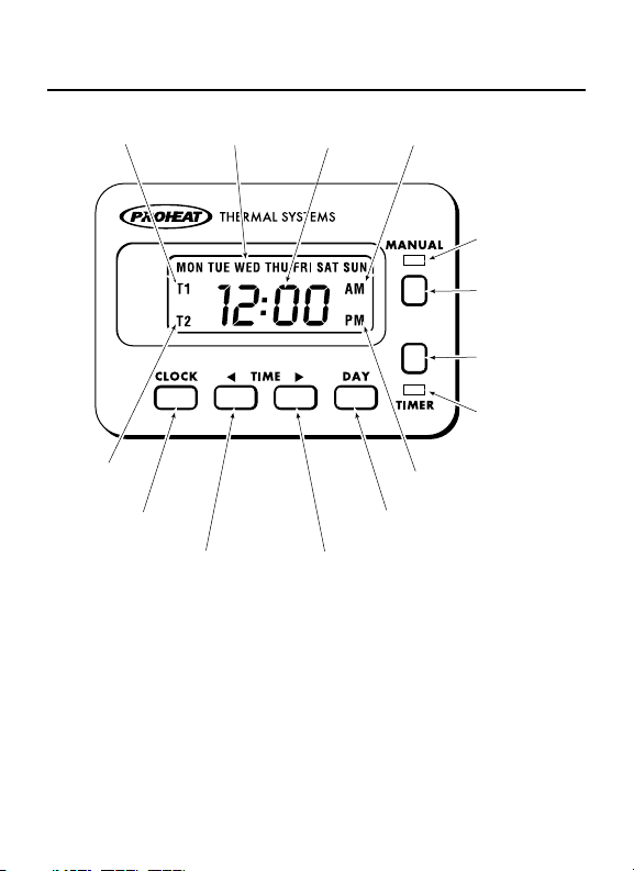
T1 PROGRAM
INDICATOR
T2 PROGRAM
INDICATOR
CLOCK
DAY OF
THE WEEK
TIME BACK
TIME AM INDICATOR
HEATER
T-II
DAY ADVANCE
TIME FORWARD
ACTIVATED
LED (RED)
MANUAL
BUTTON
TIMER
BUTTON
TIMER
ACTIVATED
LED (GREEN)
PM INDICATOR
Page 3

General Description
The Proheat T-II 7 Day Digital Timer Features
• Two Timer Modes Available
– Single Timer Mode (T1). Used for a
– Dual Timer Mode (T1 and/or T2). Used
• Run time duration in Timer Mode can be
•
•
•
•
• 12 or 24 hour time display
• 12 or 24 volt automatic operation
• Backlit LCD
include:
single start time, one day per week.
one or two times per day, 1, 5, 6 or 7
days per week with automatic reset.
preset for 1 or 3 hours
Lockout Mode used to prevent unauthorized
changes to all settings and Timer programs.
Stored Timer programs and all user settings
remain set in memory in the event of a
power loss.
Manual Mode with user settable maximum
runtime
Heater Diagnostic Codes displayed on LCD.
1
Page 4
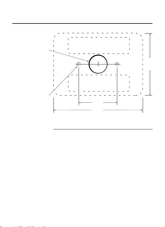
Installation
3/4" dia.
3/16" dia.
(optional)
ADHESIVE STRIP AREA
ADHESIVE
STRIP AREA
"
1-1/2
"
3-1/2
2-1/2
Dash Surface Mount
Step 1 Drill 3/4” diameter hole in centre of mounting
Step 2 Use self adhesive strips to attach Timer to
OR Drill 3/16” diameter holes (optional) according
area for connecting wires.
surface.
to diagram for mounting with studs and nuts.
"
2
Page 5
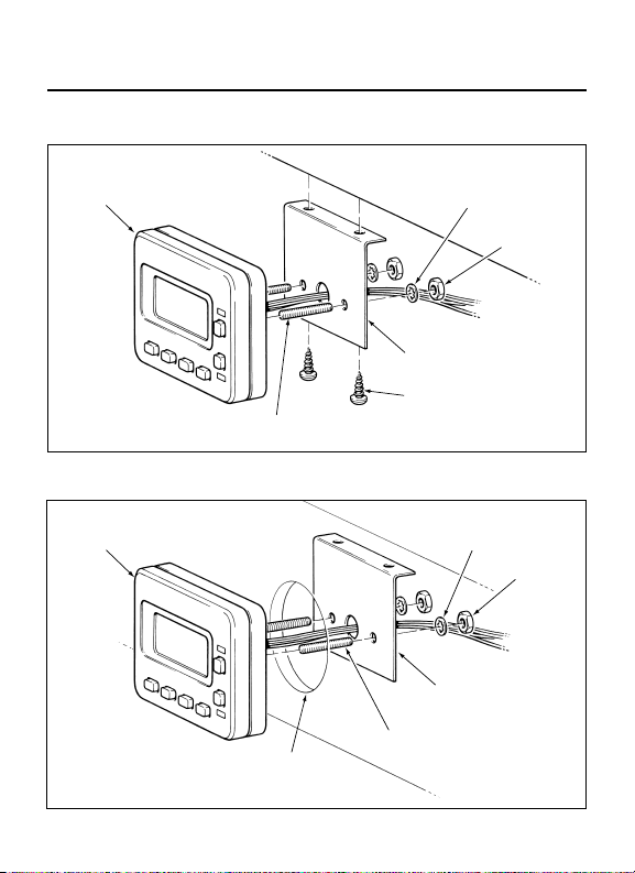
Below Dash
TIMER
STUD
DASH
BRACKET
SELF TAPPING
SCREW, USE
DRILL #25 (.149" DIA.)
WASHER
Gauge Hole
TIMER WASHER
STANDARD 2-1/8" DIA
DASH
BRACKET
STUD
GAUGE HOLE
NUT
NUT
3
Page 6
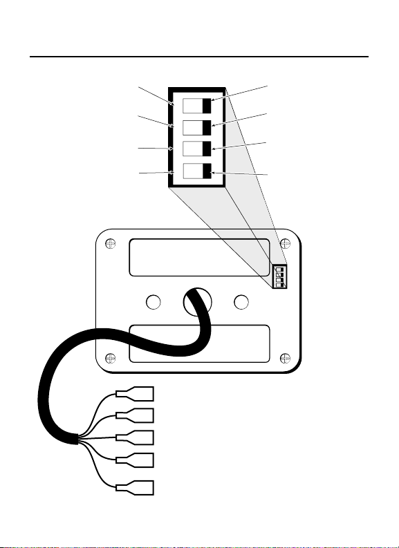
Wiring & Dip Switch Settings
1
ON
2
3
4
CLOCK MODE
24 hour clock.
TIMER RUN MODE
1 hour duration.
TIMER MODE
Dual timer, multiple days
with automatic reset.
LOCKOUT MODE
ENABLED. Prevents
changes to all settings
and Timer programs.
FACTORY SETTING
FACTORY SETTING
12 hour mode
12 hour mode
FACTORY SETTING
FACTORY SETTING
3 hour duration.
2 31
ON
4
3 hour duration.
FACTORY SETTING
FACTORY SETTING
single timer, single day.
Single timer, single day.
FACTORY SETTING
FACTORY SETTING
Lockout Mode Disabled.
DISABLED. All settings
All settings arl.
are functional.
ON
1
2 3
4
RED WIRE (power)
BLACK WIRE (ground)
GREEN WIRE (switched "ON" signal to heater)
WHITE WIRE (operational signal from heater)
(see "other heater connections" page 6)
GREY WIRE (
(see
power, keyswitch backlighting)
"
optional backlighting connections" page 6)
4
Page 7
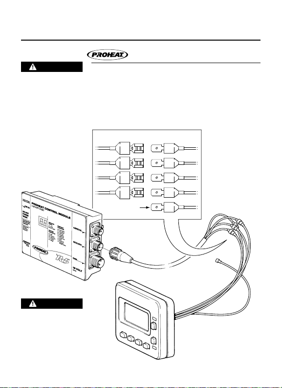
Timer Wiring
Heater Connection
CAUTION
Connect the Proheat Heater switch harness
Power to the Heater
must be discon-
• Black to Black
nected before
connecting the
Timer.
CAUTION
Miswiring the Timer
connections may
result in Timer
damage & incorrect
operation.
wires to the Timer as follows:
• Green to Green
• White to White
• Red to Red
BLACK
GREEN
WHITE
RED
TO KE Y SWITC H
(OPTIONA L)
TIMERSWITCH
BLACK
GREEN
WHITE
RED
GRAY
5
Page 8

Optional Backlighting Connections
The gray Timer wire can be connected to any
key switched power source so the Backlighting
will be on any time the key switch is on.
Other Heater Connections
If the Timer is connected to a heater which does
not have an operational signal wire, then the
white
Timer wire must be jumpered
“ON signal” wire in order for the Timer’s red “ON”
LED to light. No codes will be displayed if the
Timer is wired in this manner.
to the green
6
Page 9

Power Up
T-II
12 Hour Mode
When power is fi rst applied to the Timer or if
The screen will then change to one of the
24 Hour Mode
NOTICE
If the Lockout Mode dip switch #4 is in the
power is lost then restored, you will see the
above segment test screen along with the
Red & Green LED’s illuminated for 2 seconds.
continuously fl ashing Clock screens
, shown left
(Based on the Clock Mode dip switch #1, factory
preset: 12 hour mode) and will stay this way
until the Time of Day is set.
ENABLED position, you may see T1 and/or T2
and the Green LED illuminated (if previously
enabled). See “Lockout Mode” page 12.
7
Page 10

To Set Clock – Time & Day
T-II
STEP 1 Press & Hold “Clock”.
STEP 2 Press “W” or “X” to set time.
STEP 3 Press “Day” to set day.
STEP 4 Release “Clock”.
NOTICE
See page 4 for optional Clock Mode settings.
8
Page 11

To Set Single Timer
Single Timer, Single Day Mode
T-II
Timer set in single timer mode only will allow
STEP 1 Press & Hold “Timer”.
STEP 2 Press “W” or “X” to set “ON” time.
STEP 3 Press “Day” repeatedly to set day.
STEP 4 Release “Timer”. (Green LED and “T1” will
NOTICE
See page 4 for optional Timer Mode settings.
Example
you to set one “ON” time one day per week
and has to be manually reactivated. With the
T1 time activated, the Timer will go “ON” at the
preset time (Red and Green LED’s on), and will
be deactivated at the end of it’s duration time.
To reactivate the Timer press “Timer”.
(Green LED will go on & “T1” will fl ash.)
remain lit to indicate active Timer.)
Highway Truck parked for the weekend. Set Timer
T1 at 6:00 a.m. for Monday. The heater will switch
on one time only and run for 1 or 3 hours (see
page 4 Timer Run Mode settings) and preheat
Truck on Monday morning before the driver
arrives at 7:00 a.m.
9
Page 12

To Set Dual Timer
Dual Timer, Multiple Day Mode
T-II
NOTICE
See page 4 for optional Timer Mode settings.
STEP 1 Press & Hold “Timer”.
STEP 2 Press “W” or “X” to set “ON” time.
STEP 3 Press “Day” repeatedly to set day(s).
STEP 4 Release “Timer”. (Green LED and “T1” will
T1 program is now activated.
STEP 5 Press & Hold “Timer”.
In the dual timer mode setting you can program
your Timer to come “ON” one day per week or,
Mon. thru Fri., Mon. thru Sat or Mon. thru
Sun. It also has a built in automatic reset
function
the Timer
(Green LED will go on & “T1” will fl ash.)
remain lit to indicate active T1 program.)
Follow steps 5 thru 8 for T2 program. (Optional)
(Green LED will remain on & “T2” will fl ash.)
so that you do not have to re-activate
after every duration time.
10
Page 13

T-II
STEP 6 Press “W” or “X” to set “ON” time.
STEP 7 Press “Day” repeatedly to set day(s).
STEP 8 Release “Timer”. (Green LED and “T2” will
STEP 9 Press “Timer” once more to activate both
NOTICE
Example School bus Timer: T1 is set at 6:00 a.m. Mon.
remain lit to indicate active T2 program.)
“T1” & “T2”. (“T1” and “T2” will remain lit to
indicate active “T1” and “T2” program.)
You can toggle through to activate or deactivate
the T1, T2 and T1 + T2 Timers by repeatedly
pressing “Timer”.
Timer will repeat each set day until switched off.
through Fri. T2 is set at 2:00 p.m. Mon. through
Fri. The heater will switch on each weekday
morning at 6 a.m. and run for 1 or 3 hours (see
page 4 Timer Run Mode settings) then switch off.
The heater will again switch on at 2 p.m. each
weekday afternoon and run for 1 or 3 hours
(see page 4 Timer Run Mode settings) then
switch off. This will automatically repeat every
weekday until the Timer is switched off.
11
Page 14

Lockout Mode
Used to prevent unauthorized changes to the
Timer (Single and Dual modes) program
You will see this screen while pressing any
Clock, Timer (Single and Dual modes)
program time settings, Timer Active (On/Off)
state and Manual Mode Runtime settings.
settings, Timer Active (On/Off) state and
Manual Mode Runtime settings will remain
set in memor y in the event of a power loss.
However the Clock will have to be set before
the Timer will function once power is
resorted. The Clock setting function will go
into Lockout Mode 5 minutes after the Clock
button is pressed (time stops fl ashing) and
the time is set.
button in Lockout Mode, except for the
Manual button. The Manual button will
function in Lockout Mode.
T-II
NOTICE
See page 4 for optional Lockout Mode settings.
12
Page 15

Manual Mode Runtime
Used to set the maximum runtime the heater
To enter the Manual Mode Runtime settings
Step 1 Press and hold the Clock and Timer buttons
The current software version will display briefl y:
While still holding Clock and Timer, the
will operate when heater is switched on by
pressing the Manual button.
simultaneously for 5 seconds.
T-II
following screen will be displayed:
T-II
13
Page 16

Step 2 Release the Clock and Timer buttons.
Step 3 Use the “W” or “X” to set the desired
Example P1:05 = 0.5 hours.
With this setting the heater will operate
Step 4
NOTICE
To enter Manual Mode Runtime settings
maximum runtime in half hour increments
from 0.5 hours to 9.5 hours.
P1:10 = 1.0 hours.
....
P1:95 = 9.5 hours.
P1:00 = infi nite (no maximum) Factory Setting.
indefi nitely until it is switched off.
Press the Clock & Timer buttons simultaneously
to exit Manual Mode Runtime Settings.
Lockout Mode must be DISABLED. See page
4 for Lockout Mode settings.
14
Page 17

Manual Heater Operation
T-II
The “Manual” button is used to turn the
heater on and off when desired regardless of
set Timers.
STEP 1 Press “Manual” to activate the heater. (Red
LED will go on and the heater will operate
indefi nitely (factory preset) or up to 9.5 hours
if Manual Mode Runtime is set.)
STEP 2 Press “Manual” again to de-activate the
heater. (Red LED will go out and the heater
will turn off.)
“Manual” & “Timer” cannot be active at the
same time. If “Manual” is active and “Timer”
is pressed, the heater will turn off and the
Red Manual LED will go out.
15
Page 18

Single Timer Single Day Mode
Timed Heater Operation
T-II
STEP 1 Press “Timer” to activate the T1 program
STEP 2 Press “Timer” to deactivate and cancel the
If “Timer” is active and “Manual” is pressed,
When the heater has been turned on by the
16
(Green Timer LED will go on). The Heater will
switch on at the set T1 program time and run
for 1 or 3 hours (see page 4 Timer Run Mode
settings) then switch of f. The Green Timer
LED will now be out. To set Timer T1 again for
the same time and day repeat step 1.
current T1 program (Green Timer LED will
go out).
“Timer” is de-activated and green LED goes out.
“T1 Timer” in single timer mode, the heater
can be turned off by pressing either “Manual”
or “Timer”. Both red and green LED’s will go
out. If Lockout Mode is ENABLED only the
“Manual” button will work.
Page 19

Dual Timer, Multiple Day Mode
STEP 1
STEP 2
If the heater has been turned on by the “T1
NOTICE
See page 4 for optional Timer Mode settings.
To activate or deactivate Timer programs Dip
Press “Timer” repeatedly to tog gle through and
activate T1, T2 and T1 + T2 Timers. (Green Timer
LED will go on). The Heater will switch on at the
set program(s) time and run for 1 or 3 hours
(see page 4 Timer Run Mode settings) then
switch off. The Timer will then automatically
repeat each set program until switched off.
Press “Timer” repeatedly to toggle through and
deactivate and cancel the current set program(s)
(Green Timer LED will go out). T1, T2 and T1 +
T2 Timers. (Green Timer LED will go off).
or T2 Timer” in dual timer mode, pressing
“Manual” will turn the heater off but leaves
the Timer(s) activated. Pressing “Timer” will
turn off the heater and de-activate the
Timer(s). If Lockout Mode is ENABLED, only
the “Manual” button will work.
switch #4 Lockout Mode must be DISABLED.
See page 4 for Lockout Mode settings.
17
Page 20

Diagnostics
When the Timer is connected to a PROHEAT
Example On an M-Series heater a repeatedly fl ashing
Please see the heater ser vice manual for the
heater, The Timer’s red “Heater Activated LED”
will be lit constantly while the heater is running
normally. In case of heater error, the Timer’s
red LED will fl ash an error code, followed by a
pause. The error code will also be displayed
on the LCD in the form “Er XX”. These errors
correspond to those displayed on the PROHEAT
Control Module (PCM) diagnostic panel.
T-II
eight pulses separated by a pause indicates
a heater Fuel Shut-Off Valve error.
Complete listing of all heater error codes,
meaning and Troubleshooting procedures.
Available for download at www.proheat.com
their
18
Page 21

M-Series
1 Start Error
2 Flame Out
3 Coolant Flow
4 Overheat
5 Voltage
6 Flame Fault
7 Temp Sensor
8 Fuel Shut-Off Valve
9 Temp Sensor T2
(G-I PCM Only)
10 Ignition Module
11 Coo lant Pump
12 Motor
13 Aux. Output
14 Switch Output
15 Indicator Output
16 System Current
17 Motor Speed Error
18 CANbus Error
X-45
1 Start Error
2 Flame Out
3 Coolant Flow
4 Overheat
5 Voltage
6 Flame Sensor
7 Temp Sensor
8 Fuel Pump
9 Compressor
10 Ignition coil
11 Coo lant pump
12 Blower
13 Sleeper Fan /
Aux. output
19
Page 22

Warranty Policy
SeaStar Solutions warrants the Proheat T-II Timer
to be free from defects in material and
workmanship under normal use and service for
two (2) years on parts and labor from the date of
fi rst installation. Replacement par ts are warranted
the remainder of the Timer’s warrant y or 90 days,
whichever is longer. This warranty applies only to
those units which are installed by a registered
PROHEAT dealer. All labor charges will be paid in
accordance with
Standard Repair Time (SRT) guidelines.
THE WARRANTIES SET FORTH HEREIN ARE THE
OWNER RESPONSIBILITIES
Before the expiration of the warranty, Owner must
NOTICE
This is a warranty summary. For the complete
SOLE WARRANTIES MADE BY SEASTAR SOLUTIONS
IN REGARD TO THE PROHEAT T-II TIMER KIT SEASTAR
SOLUTIONS MAKES NO OTHER WARRANTIES,
EXPRESS
OR FITNE SS FOR A PARTICUL AR PURPOSE.
give notice to a registered PROHEAT dealer of
failures, if any, considered to be warrantable and
deliver the defective Timer to such dealer. Owner
is responsible for the cost of all repairs made to
the engine or equipment in which it is installed,
other than the Proheat T-II Timer Kit. Owner is
responsible for lodging, meals and incidental costs
incurred by the Owner as a result of a warrantable
failure. Owner is responsible for ‘down-time’
expenses, and all business costs and losses
resulting from a warranta ble failure. SEASTAR
SOLUTIONS IS NOT RESPONSIBLE FOR INCIDENTAL
OR CONSEQUENTIAL DAMAGE S.
SeaStar Solutions’ published
OR IMPLIED, OR OF MERCHANTABILITY
warranty manual please go to www.proheat.com
20
Page 23

SeaStar Solutions
3831 No. 6 Road
Richmond, B.C.
Canada V6V 1P6
Tel: 604 - 270 - 6 899
Fax: 604-270-7172
www.proheat.com
© 2011 Mar ine Cana da Acqu isition I nc.
DBA SE ASTAR SOLU TIONS
Printed in Canada
PID# 95 8829C 0 3/14
 Loading...