


T-II TIMER
INSTALLATION & OPERATING INSTRUCTIONS

T1 PROGRAM |
DAY OF |
INDICATOR |
THE WEEK |
|
|
|
|
T2 PROGRAM
INDICATOR
CLOCK
TIME BACK
TIME |
AM INDICATOR |
HEATER
T-II ACTIVATED
LED (RED)
MANUAL
BUTTON
TIMER
BUTTON
TIMER
ACTIVATED
LED (GREEN)
PM INDICATOR
DAY ADVANCE
TIME FORWARD

General Description
The Proheat T-II 7 Day Digital Timer Features include:
•Two Timer Modes Available
–Single Timer Mode (T1). Used for a single start time, one day per week.
–Dual Timer Mode (T1 and/or T2). Used one or two times per day, 1, 5, 6 or 7 days per week with automatic reset.
•Run time duration in Timer Mode can be preset for 1 or 3 hours
•Lockout Mode used to prevent unauthorized changes to all settings and Timer programs.
•Stored Timer programs and all user settings remain set in memory in the event of a power loss.
•Manual Mode with user settable maximum runtime
•Heater Diagnostic Codes displayed on LCD.
•12 or 24 hour time display
•12 or 24 volt automatic operation
•Backlit LCD
1
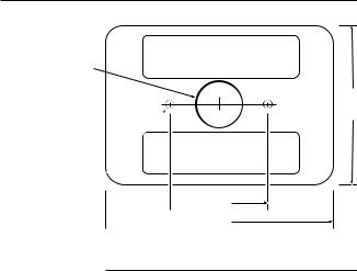
Installation
ADHESIVE STRIP AREA
3/4" dia.
ADHESIVE
STRIP AREA
3/16" dia.  (optional)
 1-1/2"
 3-1/2"
"1/2-2
Dash Surface Mount
Step 1 Drill 3/4” diameter hole in centre of mounting area for connecting wires.
Step 2 Use self adhesive strips to attach Timer to surface.
OR Drill 3/16” diameter holes (optional) according to diagram for mounting with studs and nuts.
2

Below Dash
TIMER |
DASH |
WASHER |
NUT
|
BRACKET |
|
SELF TAPPING |
STUD |
SCREW, USE |
DRILL #25 (.149" DIA.) |
Gauge Hole
TIMER |
WASHER |
DASH
NUT
BRACKET
STUD
STANDARD 2-1/8" DIA
GAUGE HOLE
3

Wiring & Dip Switch Settings
CLOCK MODE
24 hour clock. 
TIMER RUN MODE
1 hour duration.
TIMER MODE
Dual timer, multiple days with automatic reset.
LOCKOUT MODE  ENABLED. Prevents
changes to all settings and Timer programs.
FACTORY SETTING
 12 hour mode
FACTORY SETTING
 3 hour duration.
FACTORY SETTING sSingle timer, single day.

 FACTORY SETTING
LockoutDISABLED. All settings
All
are functional.
1 |
|
|
ON |
2 |
|
|
|
|
|
|
|
3 |
|
|
|
|
|
|
|
4 |
|
|
|
 RED WIRE (power)
 BLACK WIRE (ground)
 GREEN WIRE (switched "ON" signal to heater)
WHITE WIRE (operational signal from heater) (see "other heater connections" page 6)
 GREY WIRE (power, keyswitch backlighting) (see "optional backlighting connections" page 6)
4

Timer Wiring
 CAUTION
Power to the Heater must be disconnected before connecting the Timer.
 Heater Connection
Connect the Proheat Heater switch harness wires to the Timer as follows:
•Black to Black
•Green to Green
•White to White
•Red to Red
SWITCH |
TIMER |
BLACK |
BLACK |
GREEN |
GREEN |
WHITE |
WHITE |
RED |
RED |
TO KEY SWITCH |
GRAY |
|
|
(OPTIONAL) |
|
 CAUTION
Miswiring the Timer connections may result in Timer damage & incorrect operation.
5
 Loading...