

Page 1
TIME R
INSTALLATIO N
& OPERATING
INSTRUCTIONS
Page 2
General Description
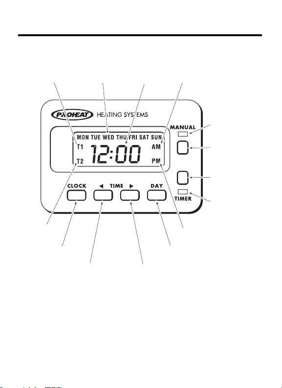
DAY OF
THE WEEK
TIME AM INDICATOR
T2 PROGRAM
INDICATOR
T1 PROGRAM
INDICATOR
CLOCK
TIME RETARD
TIME ADVANCE
DAY ADVANCE
TIMER
ACTIVATED
LIGHT (GREEN)
HEATER
ACTIVATED
LIGHT (RED)
TIMER
BUTTON
MANUAL
BUTTON
PM INDICATOR
Page 3

The 7 Day Digital Timer can be preset for a
single start time, one day at a time or two
programmed start times per day constantly
activated for multiple days of the week. The
clock can be preset for 12 or 24 hour time
display. The heater run time duration can be
preset for 1 or 3 hours. The manual button
can be used to override the program and run
the heater indefinitely until it is switched off.
NOTE: The time must be set for the vehicle system
voltage. (see page 4)
If power to the Timer is interrupted,
the display will flash “12:00 am MON”
in 12 hour format or “00:00 MON”
in 24 hour format. Stored programmed
times will remain set in memory.
1
Page 4
Installation
1
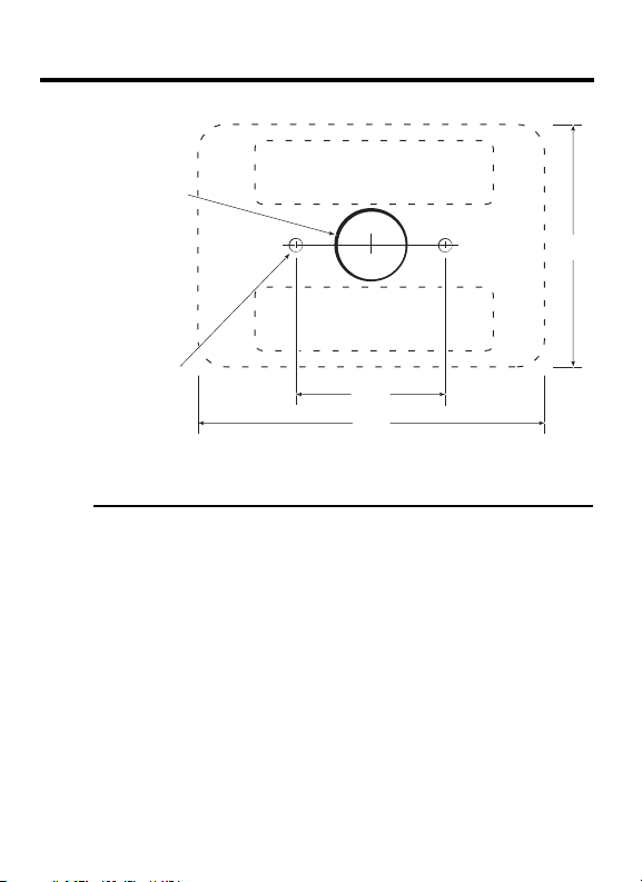
1/2"
3/4" dia.
3/16" dia.
(optional)
3
1/2"
2
1/2"
ADHESIVE STRIP AREA
ADHESIVE
STRIP AREA
Dash Surface Mount
2
STEP 1 Drill 3/4" diameter hole in centre
of mounting area for connecting wires.
STEP 2 Use self adhesive strips to attach Timer
to surface.
OR Drill 3/16" diameter holes (optional)
according to diagram for mounting
with studs and nuts.
Page 5
Below Dash
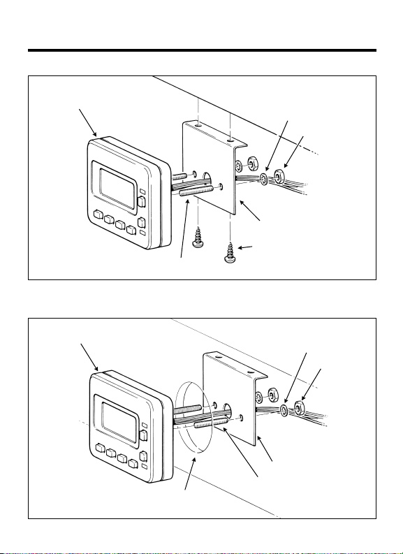
TIMER
Gauge Hole
TIMER
STANDARD 2 1/8" DIA
GAUGE HOLE
DASH
STUD
DASH
BRACKET
SELF TAPPING
SCREW, USE
DRILL #25 (.149" DIA.)
STUD
WASHER
NUT
WASHER
NUT
BRACKET
3
Page 6
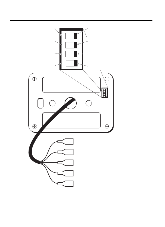
Wiring & Dip Switch Settings
ON
2 31
4
TIM ER
RED WIRE (power)
BLACK WIRE (ground)
GREY WIRE (keyswitch
backlighting optional)
GREEN WIRE
(“ON” signal to heater)
WHITE WIRE (operational
signal from heater)
(see “Note:” under Proheat
Heater Connection)
CLOCK MODE
24 hour clock
TIMEOUT MODE
1 hour duration
SYSTEM MODE
dual timer, multiple days
with automatic reset
FACTORY SETTING
12 hour mode
FACTORY SETTING
3 hour duration
FACTORY SETTING
single timer, single day
1
ON
2 3
4
FACTORY SETTING
12 volts
VOLTAGE MODE
24 volts
NOTE: Before using Timer, set the
4
Dip Switch settings for your application.
Page 7

PROHEAT Heater Connection
CAUTION: Power to the controller must be dis-
CAUTION: Mis-wiring the Timer connections may result
connected before connecting the Timer.
Connect the heater switch harness wires
to the Timer as follows:
• Black to Black
• Green to Green
• White to White
• Red to Red
in Timer damage
Other heater connections
NOTE: If the Timer is connected to a heater which
does not have an operational signal wire,
then the white Timer wire must be jumpered
to the green “ON signal” wire in order for
the Timer’s red “ON” indicator to light.
5
Page 8
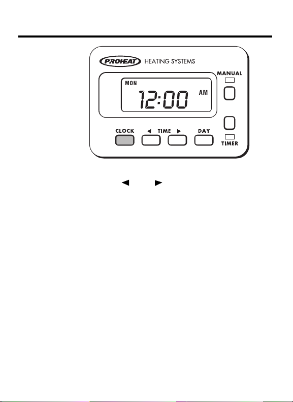
To Set Clock – Time & Day
STEP 1 Press & Hold “Clock”.
STEP 2 Press “ ” or “ ” to set time.
STEP 3 Press “Day” to set day.
STEP 4 Release “Clock”.
NOTE: 12 or 24 hour option is set using
6
Dip switch No. 1 on back of Timer.
ON = 12 hour mode
OFF = 24 hour mode
(factory preset: 12 hour mode)
Page 9
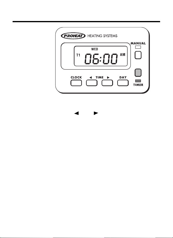
To Set Timer (single timer mode)
STEP 1 Press & Hold “Timer”.
(Green light will go on & “T1” will flash.)
STEP 2 Press “ ” or “ ” to set “ON” time.
STEP 3 Press “Day” to set day.
STEP 4 Release “Timer”. (Green light and “T1”
will remain lit to indicate active Timer.)
Timer set in the single timer mode only
will allow you to set one “ON” time.
With the T1 time activated, the Timer will
go “ON” at the preset time, and will be
de-activated at the end of it’s duration time.
To re-activate the Timer press “Timer”.
NOTE: When set time is reached, heater
switches on. Red and green lights are on.
1 or 3 hour duration option is set using
Dip switch No.2 on back of Timer.
ON = 3 hour duration
OFF = 1 hour duration
(factory preset: 3 hour duration)
7
Page 10
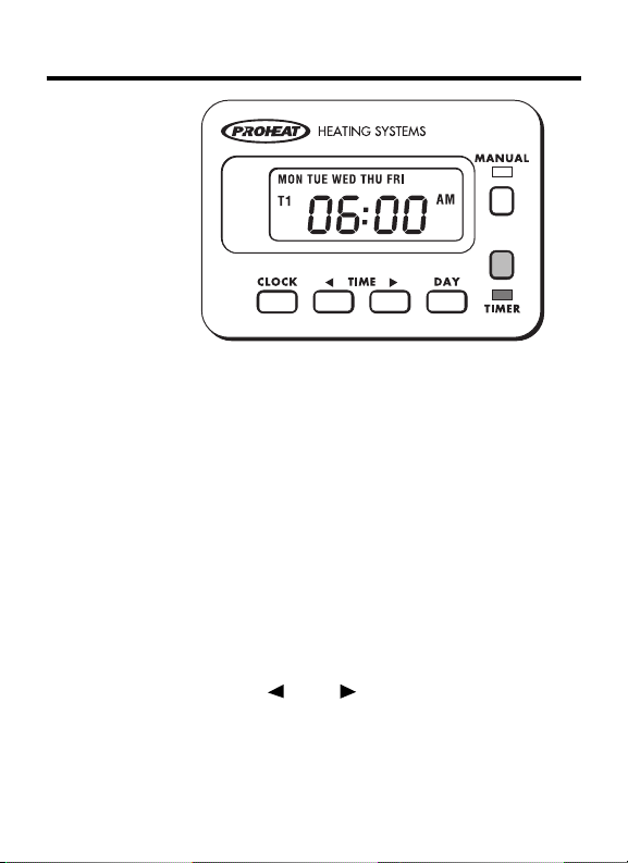
To Set Timer (dual timer mode)
In the dual timer mode setting you can
program your Timer to come “ON” daily,
Mon thru Fri, Mon thru Sat or Mon thru
Sun. It also has a built in repeat function so
that you do not have to re-activate the
Timer after ever y duration time.
NOTE: In dual timer mode you can set T1, T2
STEP 1 Press & Hold “Timer”.
STEP 2 Press “ ” or “ ” to set “ON” time.
STEP 3 Press “Day” to set day(s).
STEP 4 Release “Timer”. (Green light and “T1”
8
or both T1 & T2.
Timer mode option is set using
Dip switch No.3 on back of Timer.
ON = single timer (T1 only)
OFF = dual timer (T1 and T2)
(factory preset: T1 only)
(Green light will go on & “T1” will flash.)
will remain lit to indicate active T1 program.)
T1 program is now activated.
Follow steps 5 thru 8 for T2 program.
Page 11
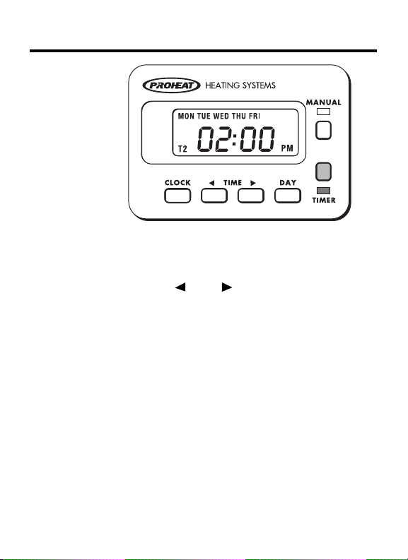
STEP 5 Press & Hold “Timer”.
(Green light will remain on & “T2” will
flash.)
STEP 6 Press “ ” or “ ” to set “ON” time.
STEP 7 Press “Day” to set day(s).
STEP 8 Release “Timer”. (Green light and “T2” will
remain lit to indicate active T2 program.)
STEP 9 Press “Timer” once more to activate
both “T1” & “T2”. (“T1” and “T2” will
remain lit to indicate active “T1” and “T2”
program.)
NOTE: Timer will repeat each set day
until switched off.
Example: School bus Timer set T1 at 6:00 a.m.
Monday through Friday.
Set T2 at 2:00 p.m. Monday through
Friday.
Timer will repeat each cycle
each week until it is switched of f.
9
Page 12
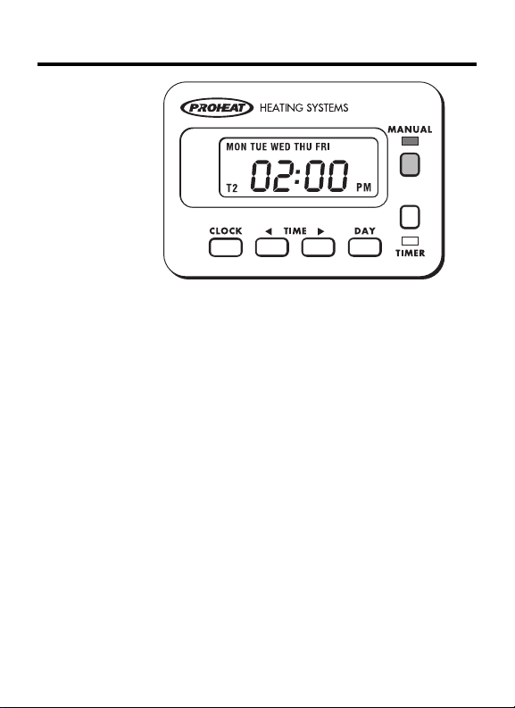
Manual & Timed Heater Operation
The “Manual” button is used to turn the heater
on and of f when desired.
STEP 1
STEP 2 Press “Manual” again to de-activate the heater.
NOTE: “Manual” & “Timer” cannot be active at the
10
Press “Manual” to activate the heater. (Red light
will go on and the heater will operate indefinitely.)
(Red light will go out and the heater will turn off.)
same time. If “Manual” is active and “Timer”
is pressed, the heater will turn of f and the red
light goes out.
If “Timer” is active and “Manual” is pressed,
“Timer” is de-activated and the green light
goes out.
When the heater has been turned on by the
“T1 Timer” in single timer mode, the heater
can be turned off by pressing either “Manual”
or “Timer”. Both red and green lights will go out.
If the heater has been turned on by the “T1
or T2 Timer” in dual timer mode, pressing
“Manual” will turn the heater off but leaves
the Timer(s) activated. Pressing “Timer” will
turn of f the heater and de-activate the Timer(s).
Page 13

Diagnostics
When the Timer is installed on a PROHEAT
heater, the Timer's red 'Heater activated
light' will be lit constantly while the heater
is running normally. In the case of a heater
error, the Timer's red light will flash an
error code followed by a pause.
Example: Repeatedly flashing five pulses separated
by a pause indicates a heater voltage error.
The PROHEAT heater error codes
are as follows:
1 Flash .............Start error
2 Flashes..........Flame out
3 Flashes..........Coolant flow
4 Flashes..........Overheat
5 Flashes..........Voltage
6 Flashes..........Flame sensor
7 Flashes..........Temp sensor
8 Flashes..........Fuel pump
9 Flashes..........Compressor
10 Flashes..........Ignition coil
11 Flashes..........Coolant pump
12 Flashes..........Blower
13 Flashes..........Sleeper fan
These errors cor respond to those
displayed on the PROHEAT Control
Module diagnostic panel.
11
Page 14

12
Page 15

Warranty Policy
SeaStar Solutions warrants the Timer to be free from defects
in material and workmanship under normal use and service for
two (2) years on parts and one (1) year on labor from the date
of first installation. Replacement par ts are warranted the
remainder of the Timer's warranty or 90 days, whichever is
longer. This warranty applies only to those units which are
installed by a registered PROHEAT dealer. All labor charges
will be paid in accordance with SeaStar Solutions' published
Standard Repair Time (SRT) guidelines.
THE WARRANTIES SET FORTH HEREIN ARE THE SOLE
WARRANTIES MADE BY SEASTAR SOLUTIONS IN REGARD TO
THE SEASTAR SOLUTIONS TIMER KIT. SEASTAR SOLUTIONS
MAKES NO OTHER WARRANTIES, EXPRESS OR IMPLIED, OR
OF MERCHANTABILITY OR FITNESS FOR A PARTICULAR
PURPOSE.
OWNER RESPONSIBILITIES
Before the expiration of the warranty, Owner must give notice
to a registered PROHEAT dealer of failures, if any, considered
to be warrantable and deliver the defective Timer to such dealer.
Owner is responsible for the cost of all repairs made to the
engine or equipment in which it is installed, other than the
SeaStar Solutions Timer Kit. Owner is responsible for lodging,
meals and incidental costs incurred by the Owner as a result
of a warrantable failure. Owner is responsible for ‘down-time’
expenses, and all business costs and losses resulting from a
warrantable failure. SEASTAR SOLUTIONS IS NOT RESPONSIBLE
FOR INCIDENTAL OR CONSEQUENTIAL DAMAGES.
13
Page 16

SeaStar Solutions
3831 No.6 Road
Richmond, BC
Canada V6V 1P6
Tel: (604) 270-6899
Fax: (604) 270-7172
© 1993 Marine Canada Acquisition Inc.
DBA SEASTAR SOLUTIONS
Printed in Canada
PID 958828-1A 06/14
 Loading...