


X45

INSTALLATION AND SE R V I C E M A N U A L
PROHEAT X45
Rev. H

CONTENTS
A. SAFETY .
B. INTRODUCTION .
..................................................................................... A-1
........................................................................ B-1
C. MODEL DESCRIPTIONS............................................................ C-1
1.0 TECHNICAL SPECIFICATIONS ................................................. 1-1
1.1 PHYSICAL – X45 ..................................................................... 1-2
1.2 ELECTRICAL – X45 .................................................................. 1-4
1.3 TORQUE SPECIFICATIONS ........................................................ 1-6
2.0 OPERATING YOUR PROHEAT HEATER..................................... 2-1
3.0 INSTALLATION .......................................................................... 3-1
3.1 LOCATING THE HEATER ........................................................... 3-2
3.1.1 Select Your Location ...................................................... 3-2
3.1.2 General considerations................................................... 3-2
3.1.3 Mounting the Proheat Heater in an Enclosure................... 3-3
3.2 MOUNTING THE HEATER .......................................................... 3-4
3.2.1 Option A – Heater With Enclosure .................................... 3-4
3.2.1 Option B – Heater Without Enclosure ............................... 3-5
3.3 EXHAUST PIPE CONNECTION.................................................... 3-6
3.4 PLUMBING THE SYSTEM.......................................................... 3-7
3.4.1 General Considerations .................................................. 3-7
3.4.2 Option A – Engine Heat or Supplemental Heat .................. 3-8
3.4.3 Option B – Engine and Sleeper Heat ................................ 3-9
3.5 WIRING & ELECTRICAL CONNECTIONS.................................... 3-10
3.5.1 General Considerations ................................................ 3-10
3.5.2 Power Connection to Batteries ...................................... 3-11
3.5.3 Timer Connections (Optional) ........................................ 3-12
3.5.4 On/Off Switch Connections ........................................... 3-13
3.5.5 Sleeper Fan Model Heater Wiring Details ....................... 3-14
3.5.6 Option A – OEM Heater & Proheat Thermostat ................ 3-14
3.5.7 Option B – OEM Heater & Thermostat............................ 3-15
3.5.8 Option C – Auxiliary Sleeper Heater................................ 3-16
3.5.9 Option D – Auxiliary Sleeper Heater Current Limited ........ 3-17
3.5.10 Auxiliary Input Model Heater Wiring Details................... 3-18
3.5.11 Option A –
3.5.12 Option B –
3.5.13 Option C – Standard Mode & Supplemental Mode .........3-20
3.6 FUEL SYSTEM ....................................................................... 3-22
3.6.1 General Considerations ................................................ 3-22
3.6.2 Option A – 1/4" or 1/2" NPT Port ................................. 3-23
3.6.3 Option B – Existing Blank Fuel Sender Cover Plate .......... 3-24
3.6.4 Option C – Hole Drilled into Fuel Tank ............................ 3-24
3.6.5 Installation .................................................................. 3-25
3.7 FIRST TIME STARTUP............................................................. 3-26
Preheat Mode Supplemental Mode Operation
Preheat and Supplemental Mode
................... 3-20
... 3-19
4.0 PRINCIPLES OF OPERATION ................................................... 4-1
4-1 GENERAL DESCRIPTION ........................................................... 4-1
4-2 MODES OF OPERATION ............................................................ 4-5
4.2.1 Standard Mode – All Models ........................................... 4-5
4.2.2 Preheat Mode – Aux Input Models Only ............................ 4-6
4.2.3 Supplemental Mode – Aux Input Models Only ................... 4-7
i

5.0 TROUBLESHOOTING & REPAIR .
5.0.1 Troubleshooting a Problem........................................ 5-1
.0.2 Example Proheat Behavior Error – Code 01................. 5-2
5
5-1 OPERATION INDICATORS, FUNCTION & COMPONENT
IAGNOSTICS ................................................................... 5-3
D
5.1.1 Operation Indicators ................................................. 5-4
5.1.2 Function Diagnostics ................................................ 5-5
1 Start ................................................................... 5-5
0
02 Flame Out ......................................................... 5-15
03 Coolant Flow ..................................................... 5-16
04 Overheat ........................................................... 5-17
05 Voltage ............................................................. 5-18
5.1.3 Component Diagnostics................................................ 5-19
06 Flame Sensor.................................................... 5-19
07 Temp Sensor .................................................... 5-21
08 Fuel Pump......................................................... 5-23
09 Compressor ...................................................... 5-23
10 Ignition Coil....................................................... 5-25
11 Coolant Pump ................................................... 5-27
12 Blower .............................................................. 5-30
13 Sleeper Fan ...................................................... 5-32
14 Hour Meter (Auxiliary Output).............................. 5-33
5-2 COMPONENT MECHANICAL OR ELECTRICAL PROBLEMS ........... 5-34
5.2.1 Fuel Nozzle .................................................................. 5-34
5.2.2 Fuel Regulator.............................................................. 5-34
5.2.3 Air Compressor ............................................................ 5-34
5.2.4 Fuel Pump ................................................................... 5-34
5.2.5 Ignition Electrode ......................................................... 5-34
5.2.6 Coolant Pump .............................................................. 5-34
5.2.7 Blower ......................................................................... 5-34
5.2.8 Fuse ........................................................................... 5-35
5-3 OPERATIONAL PROBLEMS ...................................................... 5-37
5.3.1 Smoking exhaust ......................................................... 5-37
5.3.2 Low heat output ........................................................... 5-37
5.3.3 Engine temperature gauge reads low ............................. 5-37
5.3.4 Backfiring .................................................................... 5-37
.............................................. 5-1
6.0 MAINTENANCE.......................................................................... 6-1
6-1 WEEKLY MAINTENANCE ........................................................... 6-1
6-2 ANNUAL MAINTENANCE ........................................................... 6-1
6.2.1 Clean Heater Enclosure and Air Intake ............................. 6-2
6.2.2 Check Exhaust System ................................................... 6-3
6.2.3 Check Heat Exchanger.................................................... 6-3
6.2.4 Clean Flame Sensor ....................................................... 6-4
6.2.5 Check Cooling System .................................................... 6-4
6.2.6 Check Batteries ............................................................. 6-4
6.2.7 Check Fuel System......................................................... 6-5
6.2.8 Check Fuel Filter ............................................................ 6-5
6.2.9 Clean Nozzle.................................................................. 6-6
6.2.10 Replace Compressor Air Filter ....................................... 6-6
6.2.11 Check Electrical System ............................................... 6-7
6.2.12 Check Air Pressure ....................................................... 6-8
6.2.13 Check
Modes of Operation – Switch, Timer or OEM Signals
.. 6-8
7.0 APPENDICES ............................................................................ 7-1
Bulletins 951528, 967329, SB0003, PB0034, SB0062
8.0 WARRANTY ............................................................................... 8-1
ii
PROHEAT INSTALLATION & SERVICE

A.
SAFETY
Throughout this manual, you will see notes labeled DANGER, WARNING,
CAUTION and NOTICE to alert you to special instructions or precautions
concerning a particular procedure that would be hazardous if performed
incorrectly or carelessly.
Observe them carefully!
These safety alerts alone cannot eliminate all hazards. Strict compliance
with these special instructions and common sense are major accident
prevention measures.
DANGER
Immediate hazards that will result
in severe injury or death.
WARNING
Hazards or unsafe practices that
could result in severe personal
injury or death.
CAUTION
Hazards or unsafe practices that
could result in minor injury or
product or property damage.
NOTICE
Information that is important to
proper installation or maintenance,
but is not hazard-related.
SECTION A. SAFETY
A-1

SAFETY CONSIDERATIONS
WARNING
WARNING
WARNING
WARNING
WARNING
WARNING
Exhaust
Inhalation of exhaust gas (containing carbon monoxide) may cause severe personal
injury and/or death. Anyone suspected of suffering from CO inhalation should be
removed from the hazardous area and given medical assistance immediately.
Explosion Hazard
Do not operate heater where combustible fumes or airborne particles, such as sawdust, are present.
Fuel
Exercise extreme caution when working near fuel or fuel-filled equipment. Do not
operate heater during fueling operations. In addition, do not smoke or handle open
flame equipment, such as a blowtorch, around fuel.
Fire Hazard
Do not place any flammable items around the heater and exhaust pipe.
Batteries
Wear hand and eye protection when working near batteries. Do not smoke or use open
flames near batteries.
Electrical
Electric shock can cause severe personal injury, burns, and death. Before working on
any unit, disconnect the batteries. Use only approved materials and methods when
working on the electrical system and follow local electrical codes. Never work with
electricity in wet conditions or when you are feeling fatigued.
WARNING
WARNING
WARNING
DANGER
Poisons/Toxins
Fuel and coolant are toxic and in some cases, carcinogenic. Wear eye and hand
protection at all times. Remove contaminated clothing immediately and wash
contaminated skin. Do not breathe in vapors.
Moving/Hot Parts
Moving/hot parts can cause severe injury and or death. Before working on any unit,
shut it off. Do not operate any unit until protective covers have been replaced. Always
ensure bolts and clamps are correctly torqued and secured. Inspect mechanical components periodically for damage and corrosion.
Coolant
Never remove the filler cap when the engine is hot – escaping steam or scalding water
could cause serious personal injury. The coolant level in the expansion tank should be
checked at least weekly (more frequently in high mileage or arduous conditions). Always
check the level when the system is cold. Unscrew the filler cap slowly, allowing the
pressure to escape before removing completely. Never run the engine without coolant.
Prevent anti-freeze coming in contact with the skin or eyes. If this occurs, rinse
immediately with plenty of water. Anti-freeze will damage painted surfaces.
Never top-up with salt water. Even when travelling in territories where the water supply
contains salt, always ensure you carry a supply of fresh (rain or distilled) water.
California Proposition 65 Warning
Do not operate heater in garages or in other closed or unventilated areas.
Diesel exhaust and some of its constituents are known to the State of California to
cause cancer, birth defects, and other reproductive harm.
Electrical components in this product may contain lead, a chemical known to the
State of California to cause cancer and birth defects and other reproductive harm.
A-2
PROHEAT INSTALLATION & SERVICE
INTRODUCTIONB.
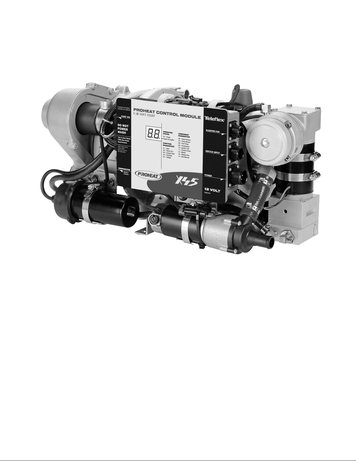
PROHEAT Model X45
This manual is provided to assist an authorized PROHEAT
dealer to install and service a PROHEAT heater. Although
trucks have been used in the examples, applications for
PROHEAT are by no means limited to trucks. PROHEAT
heaters are designed to be used on any diesel equipped
vehicle including: trucks, buses (school, transit and coach),
construction equipment, off road equipment, military
equipment and cargo.
PROHEAT heaters are used in the following applications:
(1) Engine Block Heat – PROHEAT will preheat an engine
block to ensure reliable starting in cold weather. At
the same time it may be used throughout the year to
reduce the wear associated with cold starts.
(2)
Cab or Sleeper Heat (engine off) – PROHEAT will supply
heat to the cab or sleeper. Drivers can sleep in comfort
not only in the cold of winter but also in the spring
and fall when the weather is miserable. Substantial
savings through reduced fuel consumption and engine
wear can be obtained by not idling the engine.
(3)
Supplemental Heat (engine running) – as the efficiency
of modern diesel engines are improved there is no
longer adequate reject heat available to heat the
vehicle’s interior. This is particularly true for buses.
PROHEAT can be used while the vehicle is operating
to provide supplemental heat for the interior.
(4) Cargo Heat – PROHEAT can be used to provide heat to
protect valuable cargo such as produce or beverages
from damage due to freezing.
(5) Marine – Marine applications typically involve the
engineering and installation of a complete hot-water
heating system of which PROHEAT is only one
component. Proheat recommends that only an
expert in marine hot-water heating systems install a
PROHEAT on a boat. It is the installer’s responsibility
to ensure that the installation complies with all
applicable regulations.
SECTION B. INTRODUCTION
B-1

B-2
PROHEAT INSTALLATION & SERVICE
C.
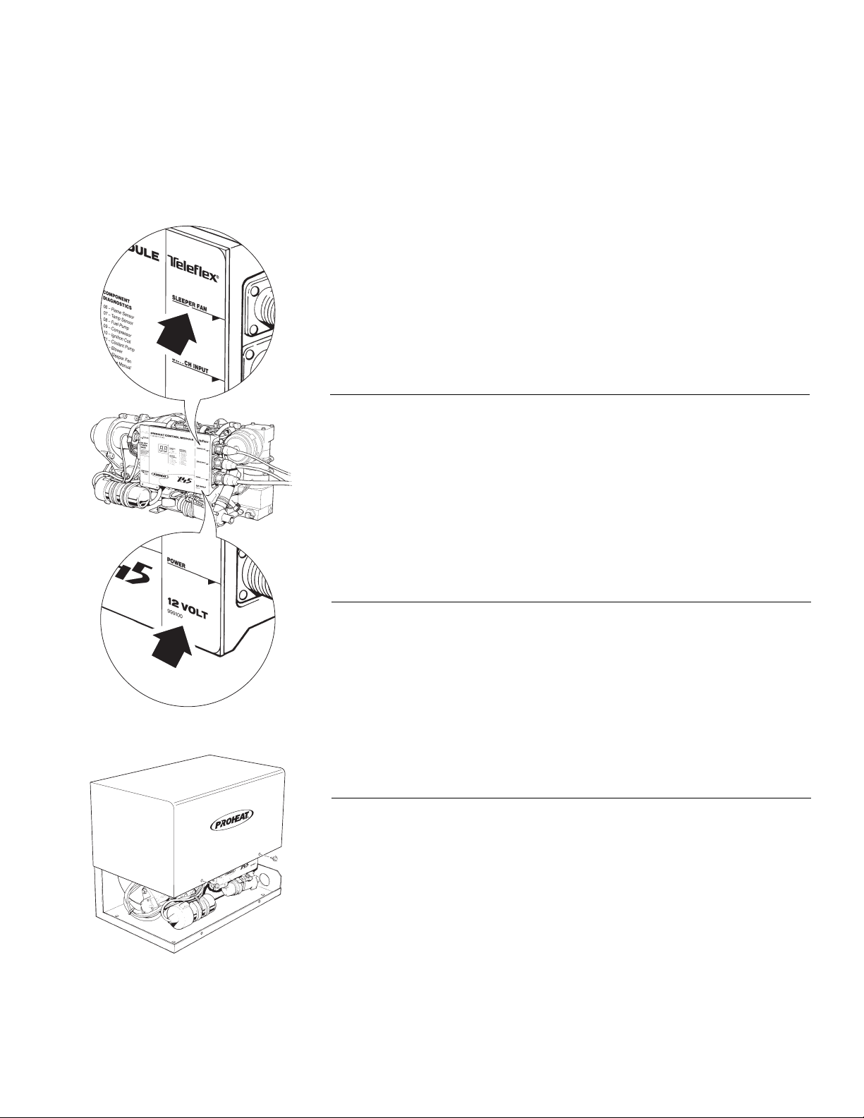
Sleeper Fan Output or Auxiliary Input
Identification.
MODEL DESCRIPTIONS
This manual covers all models of PROHEAT X45. Please refer to the X45 Parts
Book at www.proheat.com for detailed part descriptions and part numbers.
Included in the parts book are optional features such as a timer, sleeper fan
ontrol kit, impact switch (for school bus applications) and associated
c
installation and maintenance tools.
The following information describes the three general characteristics of X45
models covered in this manual: voltage, enclosure and Proheat Control Module
(PCM) options.
PROHEAT CONTROL MODULE (PCM): SLEEPER FAN
OUTPUT OR AUXILIARY INPUT
The PCM comes in either a sleeper fan output or auxiliary input model. The
sleeper fan model is limited to a 3 amp output and is generally installed on
trucks that require sleeper fan power (it is only available on 12 V models).
The
Auxiliary
Mode and Supplemental Mode. This operation is typically used for transit and
coach installation. Refer to page 4-2 for more information.
Input model uses two special input pins that allow for a Preheat
Voltage Identification.
VOLTAGE CONFIGURATION: 12 V OR 24 V
The X45 is available in either a 12 V or 24 V models.
ENCLOSURE
An optional enclosure provides environmental protection.
SECTION C. MODEL DESCRIPTIONS
C-1

C-2
PROHEAT INSTALLATION & SERVICE
1.0
TECHNICAL
SPECIFICATIONS
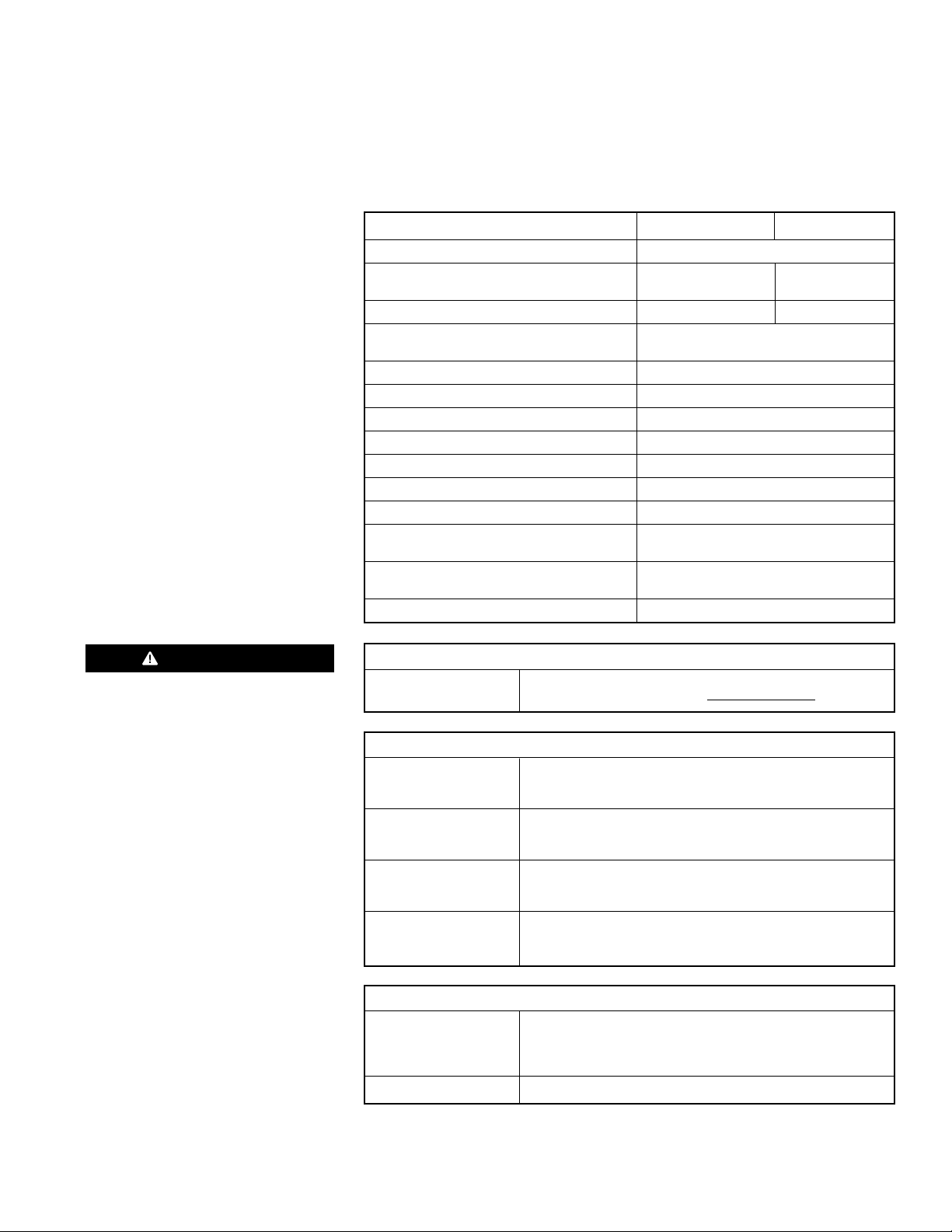
X45 12V X45 24V
RATING 45,000 BTU (13 kW)
YSTEM VOLTAGE 10 –15 VDC 20 – 30 VDC
S
ominal Voltage Range
N
CURRENT DRAW 7.5 Amps 3.75 Amps
FUEL CONSUMPTION
(Average to Maximum) 0.1 – 0.45 gal/hr. (0.4 – 1.7 L/hr.)
COOLANT FLOW 8.0 gal/min. (30 L/min.)
COOLANT TEMPERATURE (at Heater) 150°F to 185°F (65°C to 85°C)
OPERATING TEMPERATURE RANGE -40°F to +122°F (-40°C to +50°C)
IGNITION TYPE Electronic Spark Ignition
HEAT EXCHANGER CAPACITY 1 quart (0.95 L)
WEIGHT Heater ONLY 40 lbs (18 Kg)
WEIGHT Heater with Enclosure 55 lbs (25 Kg)
DIMENSIONS – HEATER (L x W x H) 18.9 x 11.2 x 10.6 inches
DIMENSIONS – ENCLOSURE (L x W x H) 20.2 x 12.3 x 10.5 inches
WARRANTY Two years parts and labor
(520 x 320 x 280 mm)
(513 x 313 x 267 mm)
DANGER
DO NOT use gasoline.
FUEL TYPES
COMPATIBLE Diesel (ULSD, #1, #2, Arctic), JP8, Jet A1
Bio Fuels – Contact Proheat www.proheat.com
SYSTEM OUTPUTS
HOUR METER Same as System Voltage
(AUXILIARY OUTPUT) Maximum 1 Amp draw (over-load shut-off protection)
High-side switched
SWITCH/TIMER Same as System Voltage
POWER Maximum 1 Amp draw (over-load shut-off protection)
High-side switched
SLEEPER FAN Same as System Voltage
(Certain Models Only) Maximum 3 Amp draw (over-load shut-off protection)
High-side switched
INDICATOR LIGHT Same as System Voltage
Maximum 1 Amp draw (over-load shut-off protection)
High-side switched
SYSTEM INPUTS
SWITCH 10 – 15 VDC (12V X45) | 20 – 30 VDC (24V X45)
Standard Run Mode
Preheat Run Mode (Certain Models Only)
Supplemental (Certain Models Only)
POWER 12 VDC or 24 VDC
SECTION 1. TECHNICAL SPECIFICATIONS
1-1
O
A
L
I
T
T
R
L
L
D
N
A
L
E
I
,
E
R
E
S
O
T
N
R
HEATERMODELNo:..........
SERIALNo:
MadeinCanadabyTeleexCanada Ltd Richmond B.C.
OPERATINGVOLTAGE:...10-16VOLTS
HEATOUTPUT:.............
PRESSURE:..............
MAX.OPERATING
FUELTYPE:...................
******
915822
9.0kW(KBTU)
2BAR(29PSI)
DIESELFUEL
X-4512V
POWER
G-IIISOFT START
PROHEATCONTROL MODULE
FUSE15A
SWITCHINPUT
SLEEPERFAN
ThisProductMeets
FHWABusHeater
Requirements
DieselFueledVechicle
CoolentHeater
ApprovedforUsein
BusApplications
12VOLT
999100
COMMINICATION
RS232&
CANBus
DONOT
POWER
WASH
ProtectedbyUSPatents
5,878,950and6,082,625
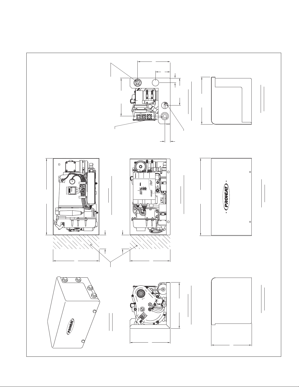
1.5 I.D.
C EXHAUST
PORT
L
Ø1.5" [38]
4.9" [125]
1.9" [49]
8.7" [222]
1.3" [33]
1.6" [41]
10.6" [270]
4.0" [101]
1.3" [34]
10.1" [258]
11.2" [285]
4.4" [112]
4X 0.38" [10]
MOUNTING HOLES
STANDARD EXHAUST PIPE
SEE NOTE 1
5.5" [140]
9.4" [239]
COOLANT OUTLET
TOP VIEW
COOLANT INLET
C EXHAUST
PORT
L
NOTES:
1/ REFER TO X45 PARTS BOOK SL9070 FOR PART
NUMBER IDENTIFICATION
2/ DIMENSIONS ARE FOR REFERENCE PURPOSES ONLY
AND SUBJECT TO CHANGE WITHOUT NOTICE
AUXILIARY MOUNTING PLATE
SEE NOTE 1
18.9" [479]
C EXHAUST
PORT
L
5.1" [129]
C EXHAUST
PORT
L
COOLANT OUTLET
CONNECTION3/4" [19]
ID HOSE1/2" NPT
HOSE FITTINGSEE
NOTE 1
FUEL SUPPLY
CONNECTION
3/16" [48] ID HOSE
SEE NOTE 1
COOLANT INLET
CONNECTION
3/4" [19] ID HOSE
LEFT SIDE VIEW
FRONT VIEW
RIGHT SIDE VIEW
AUXILIARY MOUNTING PLATE - SEE NOTE 1
TOP VIEW
MOUNT HOLE DIMENSIONS
2X 5.5" [140]
2X 7.5" [191]8.50" [216]
6.40" [163]
THIS SPACE
IS REQUIRED FOR
COMBUSTION TUBE REMOVAL
11.2" [284]
10.2" [259]
5.5" [140]
THIS SPACE
IS REQUIRED FOR
COMBUSTION TUBE REMOVAL
2.0" [50]
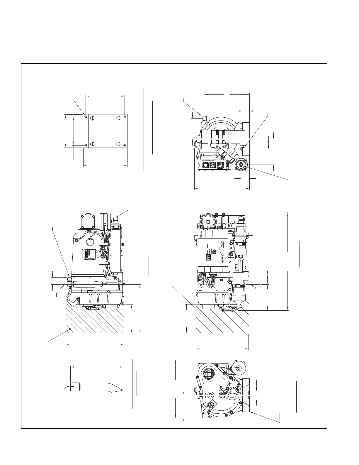
1.1
PHYSICAL – X45
X45 HEATER1.1.1
Figure 1-1 Heater Dimensions – X45
1-2
PROHEAT INSTALLATION & SERVICE
POWER
G-IIISOFT START
PROHEATCONTROL MODULE
FUSE15A
SWITCHINPUT
SLEEPERFAN
ThisProductMeets
FHWABusHeater
Requirements
DieselFueledVechicle
CoolentHeater
ApprovedforUsein
BusApplications
12VOLT
999100
COMMINICATION
RS232&
CANBus
DONOT
POWER
WASH
ProtectedbyUSPatents
5,878,950and6,082,625
O
A
L
I
T
T
R
L
L
D
N
A
L
E
I
E
R
E
S
O
T
N
R
HEATERMODELNo:..........
SERIALNo:
MadeinCanadabyTeleexCanadaLtd Richmond B.C.
OPERATINGVOLTAGE:...XX-XXVOLTS
HEATOUTPUT:.............
PRESSURE:..............
MAX.OPERATING
FUELTYPE:...................
******
XXXXXX
9.0kW(KBTU)
2BAR(29PSI)
DIESELFUEL
X-45XXV
COOLANT INLET
CONNECTION
3/4" [19] ID HOSE
COOLANT OUTLET CONNECTION
3/4" [19] ID HOSE
1/2" NPT HOSE FITTING
SEE NOTE 1
TOP VIEW
ENCLOSURE LID REMOVED
FUEL SUPPLY
CONNECTION
1/4" [48] ID HOSE
SEE NOTE 1
9.9" [252]
2X 1.4" [36]
FRONT VIEW
ENCLOSURE LID REMOVED
LEFT SIDE VIEW
ENCLOSURE LID REMOVED
RIGHT SIDE VIEW
ENCLOSURE LID REMOVED
ENCLOSURE COVER
FRONT VIEW
ENCLOSURE COVER
LEFT SIDE VIEW
20.2" [513]
10.5" [267]
20.0" [508]
10.5" [267]
12.0" [305]
8.5" [216]
ENCLOSURE COVER
RIGHT SIDE VIEW
12.3" [313]
3.8" [97]
2X 1.20" [30]
7.1" [181]
12.0" [305]
10.5" [267]
3.6" [92]
3.6" [92]
THIS SPACE
IS REQUIRED FOR
COMBUSTION
TUBE REMOVAL
ASSEMBLED
ENCLOSURE
NOTES:
1/ REFER TO X45 PARTS BOOK SL9070 FOR PART
NUMBER IDENTIFICATION
2/ DIMENSIONS ARE FOR REFERENCE PURPOSES ONLY
AND SUBJECT TO CHANGE WITHOUT NOTICE
X45 WITH ENCLOSURE1.1.2
Figure 1-2 Heater Dimensions including Enclosure – X45
SECTION 1. TECHNICAL SPECIFICATIONS
1-3
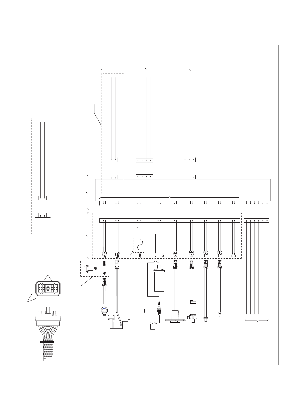
FUEL PUMP
COMPRESSOR
ELECTRODE
IGNITION
BLOWER
PUMP
FLAME
TEMPERATURE
SENSOR
SENSOR
COOLANT
B (-)BLACK/BLUE
HOUR METER (AUXILIARY OUTPUT)
12V/24V 1A MAX.
P5
COMMUNICATION
CANBUS AND
RS232
E
F
E
F
(+)RED/WHITE
(-)GREEN/WHITE
A
B
BCA
D
BCA
D
E1
F1
(-)BROWN
(-)BLACK/WHITE
(+)GRAYA
A
B
B
(+)WHITE
B
A
B
A
F3
E3
F2
E2
P1
POWER
C
C
A
B
B
A
HEATER CHASIS GROUND LUG
(GROUND VIA
COMBUSTION TUBE)
IGNITION
COIL
OVERHEAT SENSOR
D1
(-)BLACK
(+)PURPLE
(-)BLACK/PURPLE
B
(+)BLUE
B
A
A
A
B
A
B2
A2
B3
A3
(+)RED
D2
C3
P5
HEATER
INTERNAL
HARNESS
P2
SWITCH
C
C
D
D
B
A
A
B
(-)BLACK/ORANGE
(+)ORANGE
A
B
B
A
(-)PINK
(+)PINK
B
A
A
B
PLUGGED
C1
A1
B1
C2
D3
P3
SLEEPER
FAN
A
A
B
B
CONNECTOR TERMINAL
DESIGNATORS
NOTE ORIENTATION
OF CONNECTOR LUGS
(+) RED - BATTERY POSITIVE 12V/24V
(-) BLACK - BATTERY NEGATIVE
PLUGGED - NOT USED
(+) RED - POWER 12V/24V OUTPUT
(-) BLACK - GROUND
GREEN - ON SIGNAL STANDARD MODE 12V/24V INPUT
(+) WHITE - INDICATOR LAMP 12V/24V OUTPUT
(+) RED - POWER 12V/24V (3 AMP LIMIT) OUTPUT
(-) BLACK - GROUND
CAN - H
RS232 - GROUND
CAN - SHIELD
RS232 - TRANSMIT
CAN - L
RS232 - RECEIVE
E1
F1
F3
E3
F2
E2
A2
B3
D1
B2
A3
D2
C2
D3
A1
B1
C1
C3
NOTES:
1/ REFER TO X45 PART BOOK SL9070 FOR PART
NUMBER IDENTIFICATION
(+)PINK
A
B
(-)PINK
(+)ORANGE
A
(-)BLACK/ORANGE
B
(+)
(-)
(+)PURPLEA
(-)BLACK/PURPLE
B
(+)BLUEA
(-)BLACK/BLUEB
(+)BROWNA
(-)BROWNB
(+)WHITEA
(-)BLACK/WHITEB
P3
AUXILIARY
INPUT
A
B
ON SIGNAL PREHEAT MODE 12V/24V INPUT
ON SIGNAL SUPPLEMENTAL MODE 12V/24V INPUT
A
B
SEE DETAIL A FOR
AUXILIARY INPUT OPTION
DETAIL A
AUXILIARY INPUT OPTION
SEE NOTE 1
OPTIONAL IMPACT SWITCH
SEE NOTE 1
A
B
A
B
C
SEE NOTE 1
FOR HARNESS
PART NUMBERS
SEE NOTE 1
FOR HARNESS
PART NUMBERS
OPTIONAL GROUND FUSE
SEE NOTE 1
(-)BLACK/GREEN
SLEEPER FAN PCM SHOWN
SEE NOTE 1
HEATER INTERNAL HARNESS
SEE NOTE 1
10 A
1 2 3
A
BCD
E
F
A
B
C
D
E
F
HEATER INTERNAL HARNESS
18 PIN CONNECTOR PIN OUT DETAIL
1.2
ELECTRICAL – X45
Figure 1-3 Wiring Diagram – X45
1-4
PROHEAT INSTALLATION & SERVICE
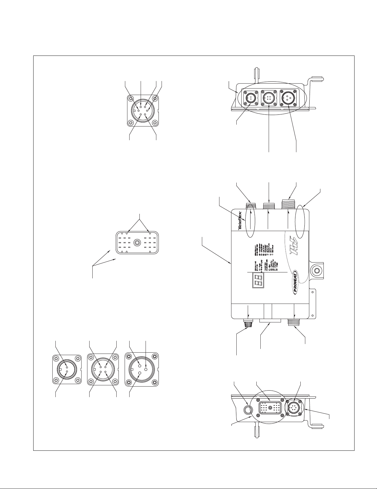
PROHEAT CONTROL MODULE
G-III SOFT START
5,878,950and 6,082,625
Protectedby US Patents
WASH
POWER
DO NOT
COMMINICATION
BusApplications
ApprovedforUse in
CoolentHeater
DieselFueledVechicle
Requirements
FHWABus Heater
ThisProduct Meets
CANBus
RS232&
FUSE 15A
999100
SLEEPER FAN
12 VOLT
SWITCHINPUT
POWER
P1 - POWER
3 PIN
P2 - SWITCH
4 PIN
P3 - SLEEPER FAN OUTPUT
OR AUXILIARY INPUT
2 PIN
SEE NOTE 1
P4 - COMMUNICATION
CANBUS AND
RS232 6 PIN
FUSE 15 A
SEE NOTE 1
P5 - HEATER
INTERNAL
HARNESS
18 PIN
PROHEAT CONTROL MODULE (PCM)
SEE NOTE 1 FOR PART NUMBER OPTIONS
1A
1B
1C
2A
2B2C
2D
3A3B
DETAIL B
DETAIL B
P1 - P3 CONNECTOR PIN OUT DETAIL
DETAIL C
2
3
1
CONNECTOR TERMINAL
DESIGNATORS
NOTE ORIENTATION
OF CONNECTOR LUGS
DETAIL C
P5 CONNECTOR PIN OUT DETAIL
ABC
DFE
CONTROLLER VOLTAGE AND
PART NUMBER IDENTIFICATION
SEE NOTE 1
SLEEPER FAN OR AUX INPUT MODEL
IDENTIFICATION - SEE NOTE 1
4A
4B
4C
4D
4E
4F
DETAIL D
DETAIL D
P4 CONNECTOR PIN OUT DETAIL
NOTES:
1/ REFER TO X45 PART BOOK SL9070 FOR PART
NUMBER IDENTIFICATION
Figure 1-4 PCM Electrical Connections – X45
SECTION 1. TECHNICAL SPECIFICATIONS
1-5
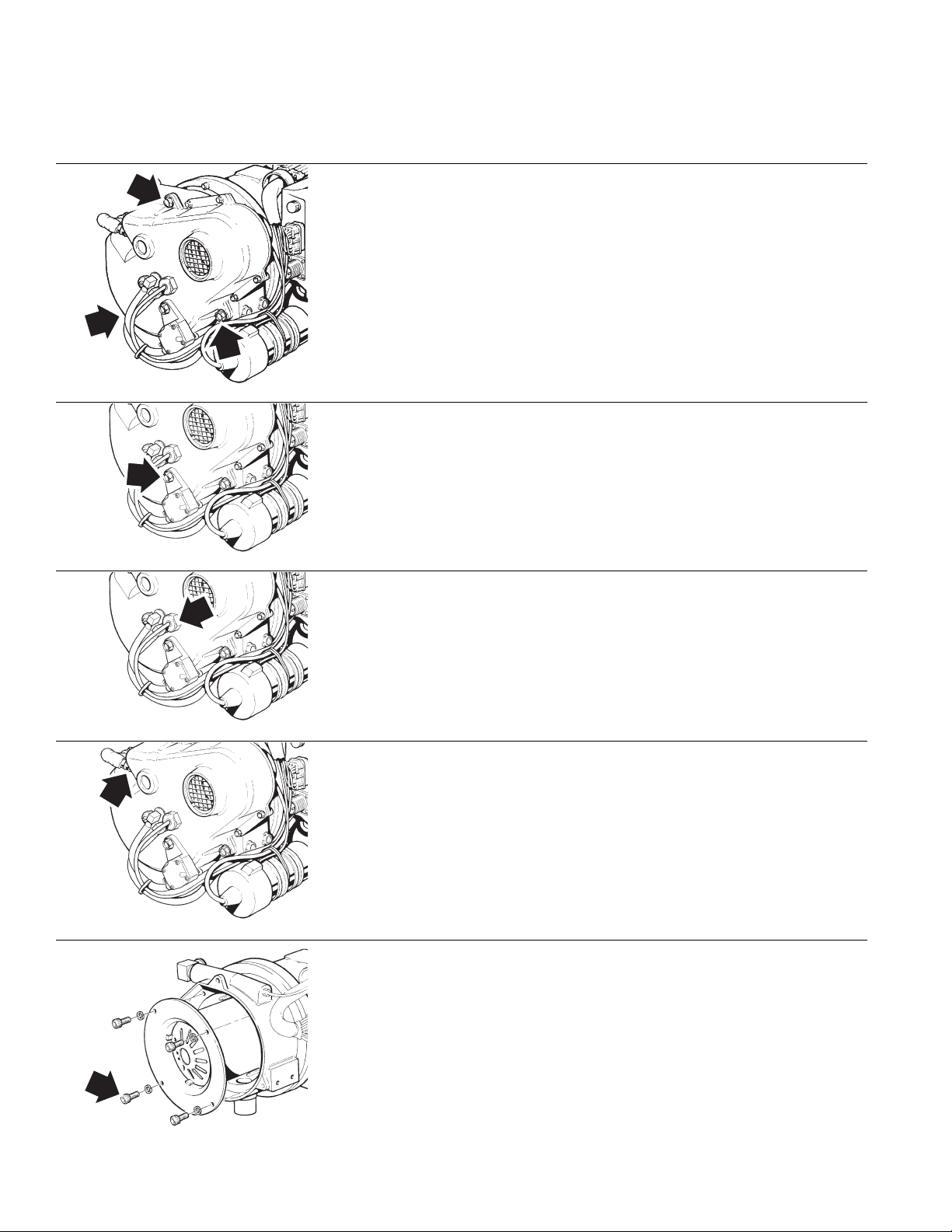
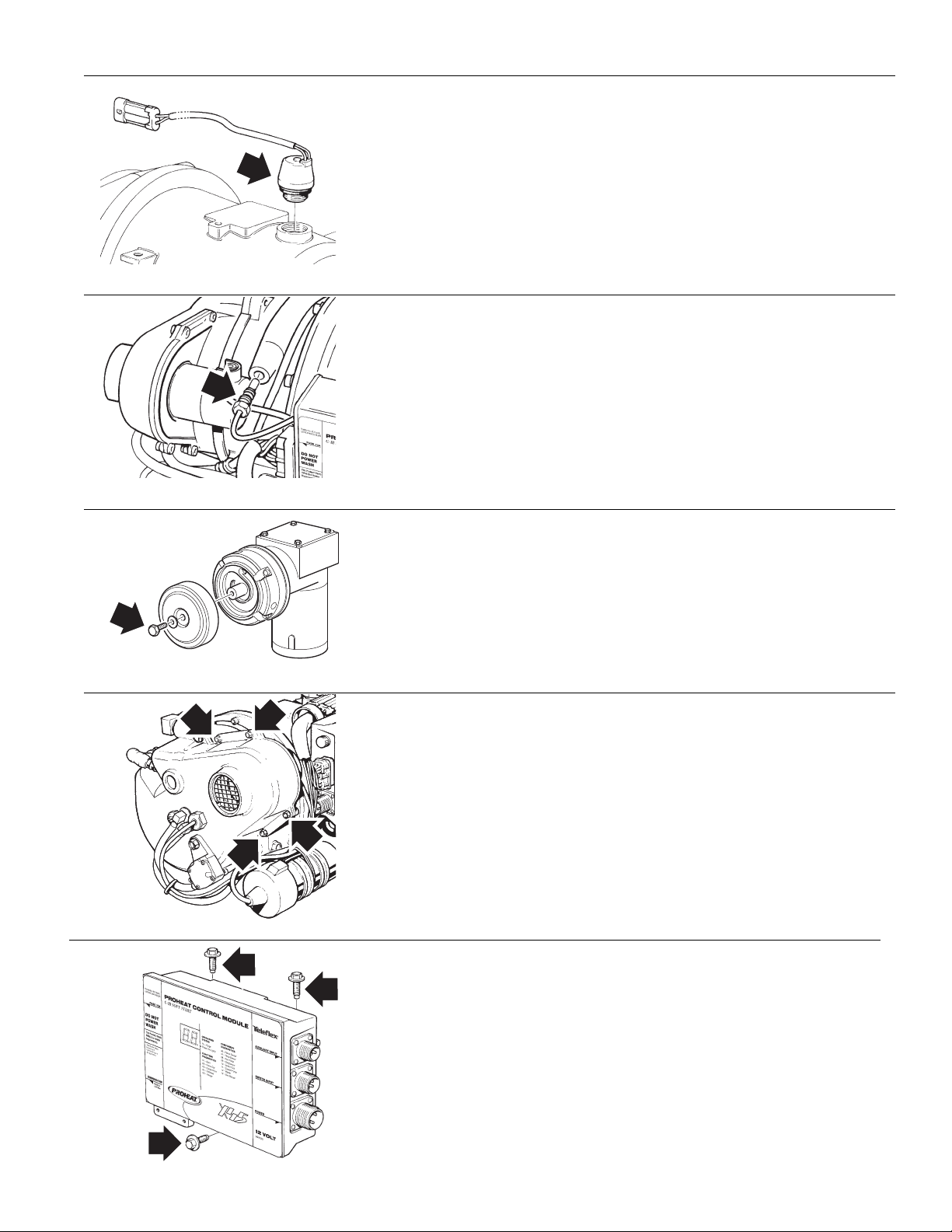
TORQUE SPECIFICATIONS1.3
FAN END CASTING
Apply anti-seize to bolts (3)
•
• Torque bolts (3) to 75±5 in/lbs (8.5±0.5 Nm)
REGULATOR
• Apply anti-seize to cap screw
• Torque cap screw to 94±6 in/lbs (10.6±0.7 Nm)
FLAME SENSOR
• Torque sensor to 25±3 in/lbs (2.8±0.3 Nm)
IGNITER
• Apply anti-seize to igniter threads
• Ensure gasket is present before installing
• Torque igniter to 50±5 in/lbs (5.6±0.6 Nm)
COMBUSTION TUBE
• Apply anti-seize to cap screws
• Torque cap screws (4) to 25±3 in/lbs (2.8±0.3 Nm)
1-6
PROHEAT INSTALLATION & SERVICE
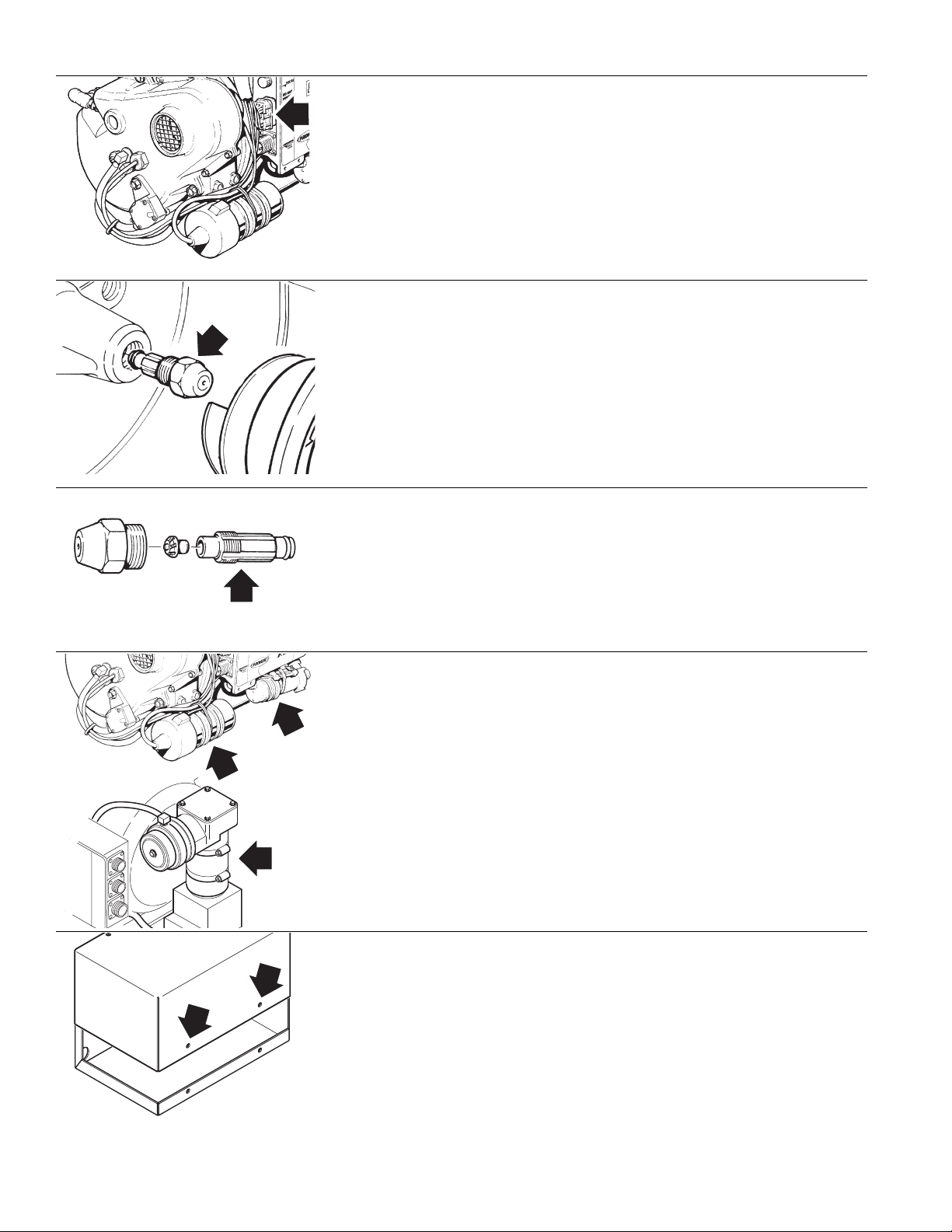
OVERHEAT SENSOR
• Lubricate o-ring with o-ring lubricant
• Torque senor to 500±50 in/lbs (56±5.6 Nm)
TEMPERATURE SENSOR
• Lubricate o-ring with o-ring lubricant
• Torque senor to 25±3 in/lbs (2.8±0.3 Nm)
AIR FILTER
• Torque cap screw to 50±5 in/lbs (5.6±0.6 Nm)
SECTION 1. TECHNICAL SPECIFICATIONS
BLOWER ASSEMBLY
• Apply anti-seize to bolts (4)
• Torque bolts (4) to 25±3 in/lbs (2.8±0.3 Nm)
PROHEAT CONTROL MODULE (PCM)
• Apply anti-seize to bolts (3)
• Torque bolts (3) to 75±7 in/lbs (8.5±0.8 Nm)
1-7
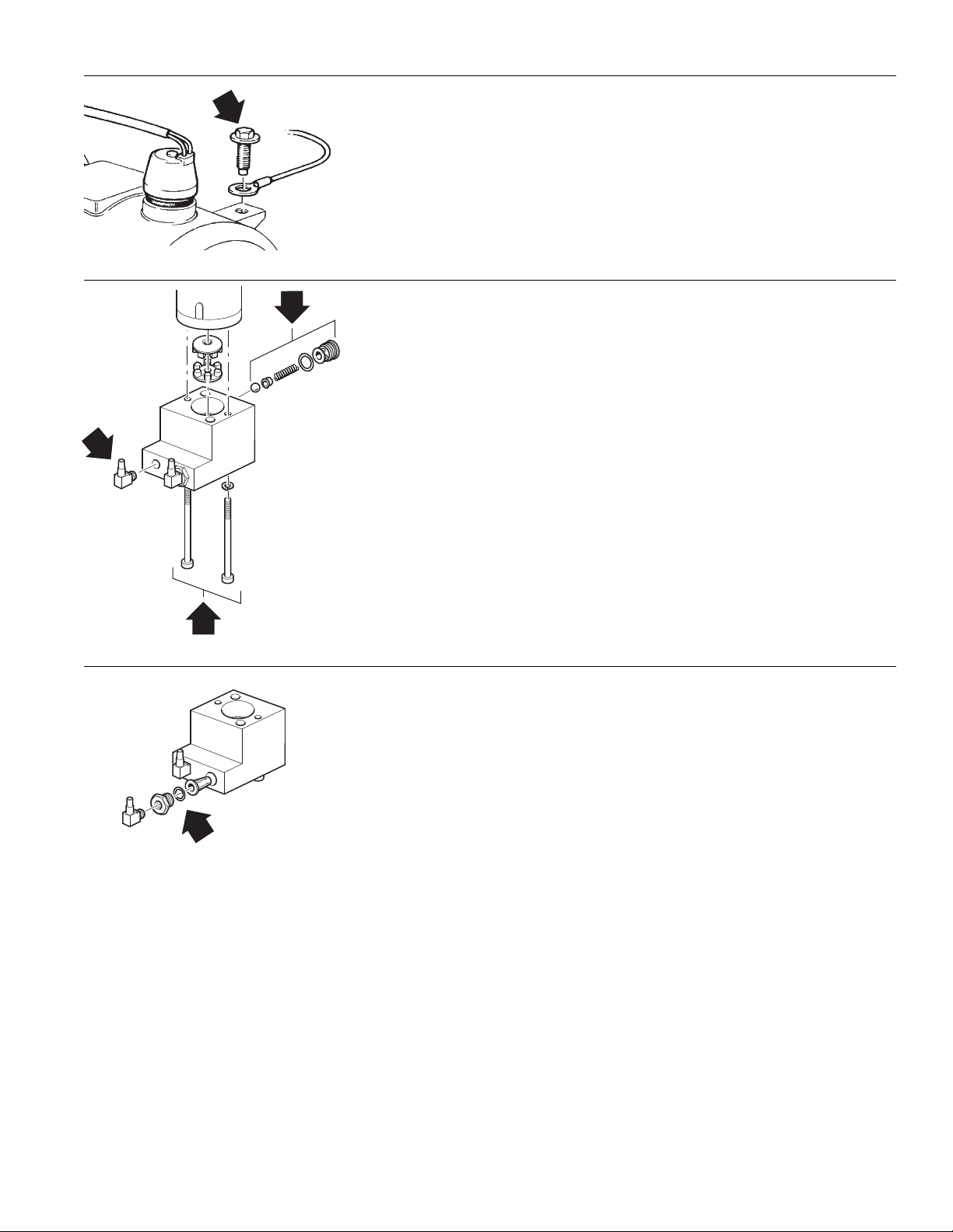
MAIN INTERNAL HARNESS
• Torque bolt (1) to 10±2 in/lbs (1.1 +/- 0.2)
NOZZLE TO FAN END
• Lubricate o-ring on nozzle with diesel
• Torque nozzle to 150±10 in/lbs (17±1.1 Nm)
NOZZLE REASSEMBLY
• Torque nozzle (1) to 30±3 in/lbs (3.4±0.3 Nm)
BAND CLAMPS
• Torque clamps (4) to 25±3 in/lbs (2.8±0.3 Nm)
ENCLOSURE LID (Optional)
• Anti-seize recommended on bolts
• Torque clamps (2) to 30±3 in/lbs (3.4±3.4 Nm)
1-8
PROHEAT INSTALLATION & SERVICE
HARNESS GROUND LUG
A
B
C
• Apply anti-seize to bolt
• Torque bolt (1) to 75±5 in/lbs (8.5±0.5 Nm)
FUEL PUMP ASSEMBLY
A
• Apply Loctite 242 to threads
• Torque bolts (2) to 25±3 in/lbs (2.8±0.3 Nm).
B
• Lubricate o-ring with diesel fuel
• Torque relief valve to 22±2 in/lbs (2.5±0.2 Nm).
C
• Apply Loctite 59241 sealant to threads
• Torque elbow (1) to 55±5 in/lbs (6.2±0.5 Nm) minimum or until
elbow is at correct orientation
FUEL FILTER
• Lubricate o-ring with diesel fuel
• Torque nut (1) to 150±10 in/lbs (17±1.1 Nm)
SECTION 1. TECHNICAL SPECIFICATIONS
1-9

1-10
PROHEAT INSTALLATION & SERVICE

2.0
OPERATING YOUR
PROHEAT HEATER
NOTICE
These instructions cover Standard
Mode operation that are normally
installed on trucks. To operate your
heater in Preheat or Supplemental,
refer to page 3-18 to page 3-20 and
page 4-6 to page 4-7.
NOTICE
Regular use of your PROHEAT
throughout the year will improve
its reliability. Weekly operation is
recommended.
NOTICE
The PROHEAT heater can be
operated by either using a toggle
switch or a 7 day timer.
Refer to page 3-10 for WIRING &
ELECTRICAL CONNECTIONS.
ENGINE HEAT ONLY
1. Switch the ON/OFF switch located in the vehicle dash to “ON.”
The switch will light and the heater will cycle on. It will continue to operate until
the coolant reaches 185˚F (85˚C) at the heater outlet and then cycle “OFF.”
When the coolant temperature falls below 150˚F (65˚C) at the heater
outlet, it will refire and repeat the cycle.
It will continue to cycle until:
a) the heater is switched “OFF,”
b) the heater runs out of fuel,
c) the vehicle battery voltage drops below 10.0 Volts, or
d) an error occurs and the switch light flashes
(See Troubleshooting & Repair, Section 5)
NOTE: The PROHEAT may be operated if the engine is running or not running.
2. When engine preheat is no longer required, switch the PROHEAT heater
“OFF.”
ENGINE AND SLEEPER HEAT
1. Switch the ON/OFF switch located in the vehicle dash to “ON.”
The switch will light and the heater will cycle on. It will continue to operate until
the coolant reaches 185˚F (85˚C) at the heater outlet and then cycle “OFF.”
When the coolant temperature falls below 150˚F (65˚C) at the heater
outlet, it will refire and repeat the cycle.
It will continue to cycle until:
a) the heater is switched “OFF,”
b) the heater runs out of fuel,
c) the vehicle battery voltage drops below 10.0 Volts, or
d) an error occurs and the switch light flashes
(See Troubleshooting & Repair, Section 5)
SECTION 2. OPERATING YOUR PROHEAT HEATER
NOTE: The PROHEAT may be operated if the engine is running or not running.
2. For sleeper heat – set the thermostat in the sleeper to the desired
temperature. If the set temperature is higher than the temperature in the
sleeper the fan will cycle “ON.” When the air reaches the set temperature
the fan will cycle “OFF.” The fan will cycle “ON” and “OFF” to maintain the
set temperature.
3. When engine and/or sleeper preheat is no longer required, switch the
PROHEAT heater “OFF.”
2-1

2-2
PROHEAT INSTALLATION & SERVICE
3.0
®
®
INSTALLATION
NOTICE
If additional installation information is
required
Dealer regarding your specific
application.
For more technical information,
please contact PROHEAT Product
Support at www.proheat.com
please contact your PROHEAT
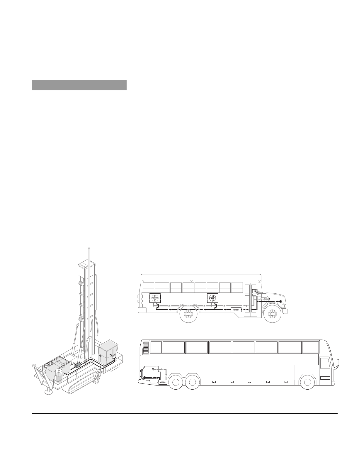
The installation details described in this manual focuses on truck applications
and does not cover all of the possible installations. As seen in the figures
below, the PROHEAT X45 is installed on a variety of equipment including
trucks, school buses, coaches, drill rigs, mine dump trucks and excavators.
In these cases the manual should be used as a guideline only.
There are seven major steps that must be completed to successfully install
the PROHEAT heater.
3.1 LOCATING THE HEATER......................................................... page 3-2
3.2 MOUNTING THE HEATER ....................................................... page 3-4
3.3 EXHAUST PIPE CONNECTION ................................................. page 3-6
3.4 PLUMBING THE SYSTEM....................................................... page 3-7
3.5 WIRING & ELECTRICAL CONNECTIONS ................................. page 3-10
3.6 FUEL SYSTEM .................................................................... page 3-22
3.7 FIRST TIME STARTUP.......................................................... page 3-26
Prior to the installation of your PROHEAT, consult your engine owner’s manual
or engine manufacturer for any restrictions or changes that may apply to
plumbing into the engine coolant system.
Figure 3-1 Other Applications.
SECTION 3. INSTALLATION
3-1
3.1
LOCATING THE HEATER
3.1.1
You Choose
CAUTION
Do not weld PROHEAT heater
mounting brackets to the
vehicle frame.
If repairs to the vehicle require
welding, disconnect the PROHEAT
power cable at the PCM. This will
prevent damage to the PROHEAT
electronics.
SELECT YOUR LOCATION
The most suitable location for mounting the heater will vary depending
on the type of vehicle. Recommended mounting locations are:
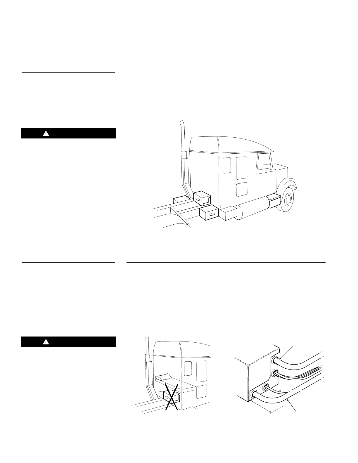
• Behind the cab across the frame rails (1).
• On either side of the frame rails (2).
• In an existing enclosure on the vehicle (step or toolbox) (3).
1
2
3
2
Figure 3-2 Recommended Mounting Positions
3.1.2
WARNING
Never locate the heater inside
the vehicle cab. (See Figure 3-3)
GENERAL CONSIDERATIONS
• Never mount the heater to two separate parts of the vehicle.
• Avoid mounting the heater in areas of excessive vibration.
• Do not mount the heater directly to the engine.
• Do not mount the heater beneath a wood floor without a proper fire wall
above the heater.
• Avoid mounting the heater in areas of excessive dust, dirt and moisture
accumulation.
• The heater must be easily accessed for service.
COOLANT OUT
FUEL IN
Figure 3-3
MINIMUM
CLEARANCE 6"
Figure 3-4 Allow minimum 6" clearance
for hose connections.
COOLANT IN
3-2
PROHEAT INSTALLATION & SERVICE
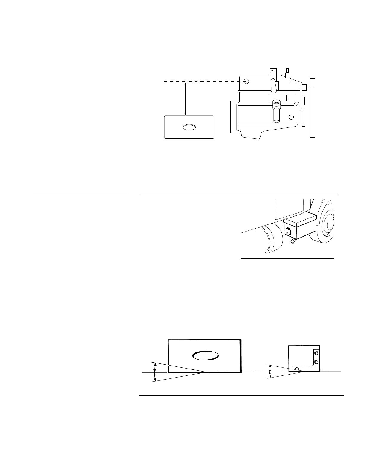
Heater must be mounted below the highest point in the cooling system. An
expansion tank may be added to the coolant system above the heater if this
is not possible.
HIGHEST POINT IN
COOLING SYSTEM
HEATER MUST
BE MOUNTED
BELOW
HIGHEST POINT
PROHEAT ENGINE OR RADIATOR
Figure 3-5 Height Requirement
3.1.3
MOUNTING THE PROHEAT HEATER IN AN ENCLOSURE
Do not locate the heater in an
airtight enclosure. If the heater is to
be mounted in an enclosure other
than the PROHEAT enclosure,
adequate air flow must be provided
to ensure proper combustion. The
enclosure must also be adequately
ventilated so that the ambient
temperature inside the enclosure
does not exceed 185 °F (85 °C).
The openings must be positioned to prevent moisture dirt and snow from
accumulating in the enclosure. The heater enclosure must be easily
accessed for servicing of the heater.
Heater must be mounted within 5˚ of horizontal, as shown.
Figure 3-6 Adequate Air Flow
SECTION 3. INSTALLATION
5˚
5˚
Figure 3-7 Mounting Angle
5˚
5˚
3-3
3.2
MOUNTING THE HEATER
Select Your Mounting Option
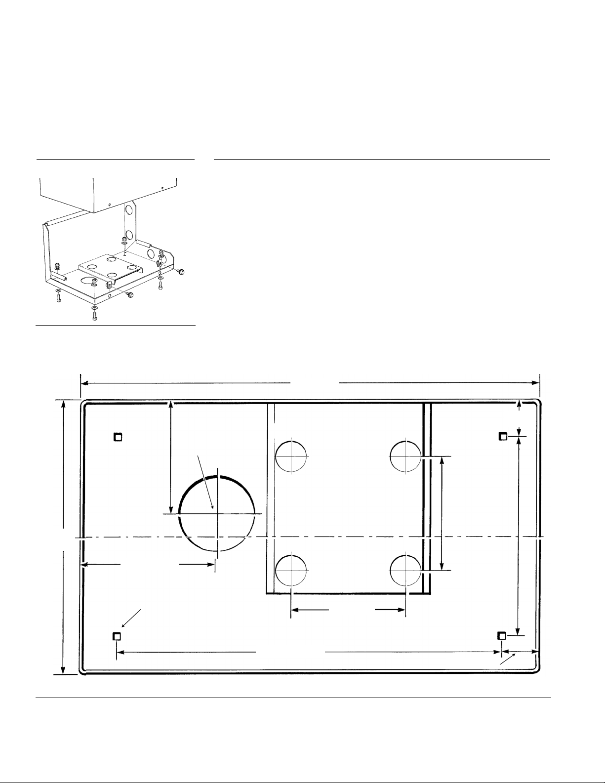
Figure 3-8 Mounting Tray
3.2.1
OPTION A
1. Remove the enclosure cover.
2. Drill the (4) mounting holes and exhaust pipe clearance hole.
3. Using the bolts supplied, fasten the enclosure to the mounting
tray or brackets.
4. Ensure that the combustion tube can be removed for service.
See Figure 1-2 on page 1-3 for service space requirements.
– Heater With Enclosure
20" (508 mm)
1 5/8"
(45 mm)
3" (76 mm) Dia.
5" (127 mm)
12"
(306 mm)
5 3/4" (146 mm)
3/4" (20 mm) MOUNTING HOLES
(4 REQUIRED)
Figure 3-9 X45 Enclosure Base Dimensions
5" (127 mm)
CENTERLINE OF ENCLOSURE
8 13/16"
(223 mm)
5" (127 mm)
16 11/16" (427 mm)
1 5/8" (45 mm)
3-4
PROHEAT INSTALLATION & SERVICE
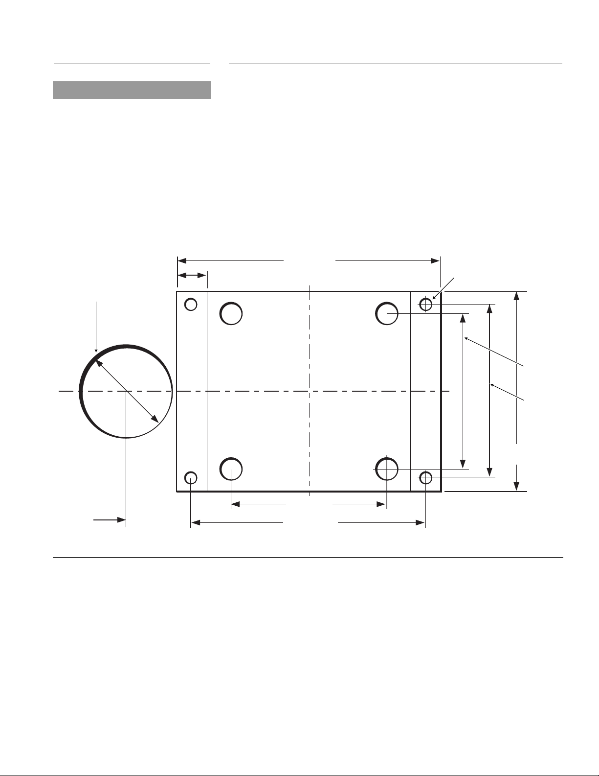
NOTICE
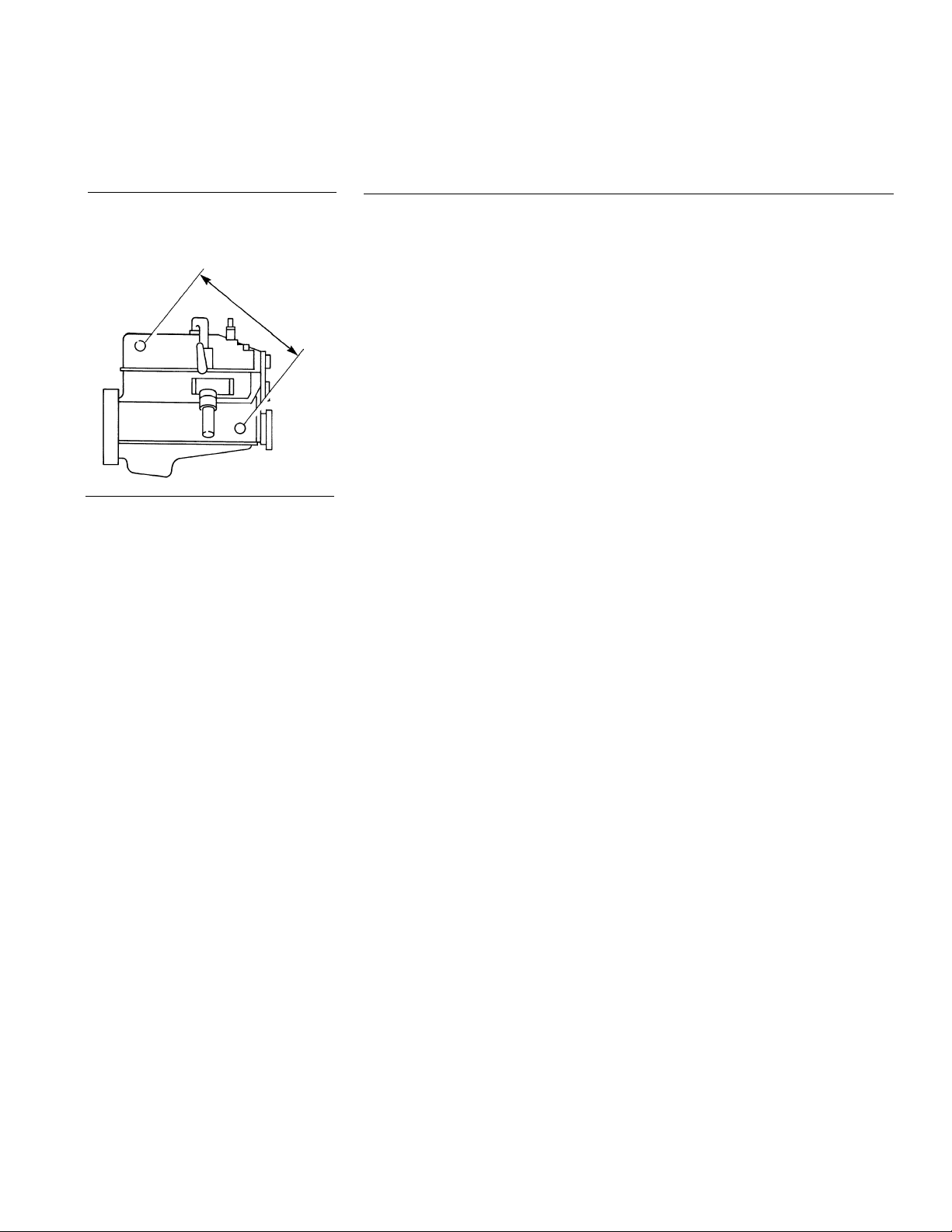
3.2.2
OPTION B
– Heater Without Enclosure
Heater supplied without an enclosure (mount in an existing enclosure on the
vehicle ie. tool box). Heater supplied with an auxiliary mounting plate.
Use anti-seize compound on fasteners
to prevent galling and corrosion.
3" (76 mm) Dia.
. Ensure that the proposed enclosure is big enough for the heater.
1
2
1
⁄2W x 11H x 201⁄2L inches (318 x 280 x 521 mm)
12
. Using the indicated dimensions, drill the (4) mounting holes
and exhaust pipe clearance hole.
3. Ensure that the combustion tube can be removed for service.
See Figure 1-2 on page 1-3 for service space requirements.
8.5" (216 mm)
1.0" (25 mm)
4 X .38" (10MM)
MOUNTING HOLES
5"
(127 mm)
2.02"
(51 mm)
Figure 3-10 X45 Mounting Plate Dimensions & Exhaust Hole
5.5"
(140 mm)
6.4"
(163mm)
5" (127 mm)
7.5" (191 mm)
SECTION 3. INSTALLATION
3-5
3.3
NOTICE
If additional information is required,
please contact your PROHEAT Dealer
regarding your specific application.
Alternatively, please contact PROHEAT
Product Support at www.proheat.com.
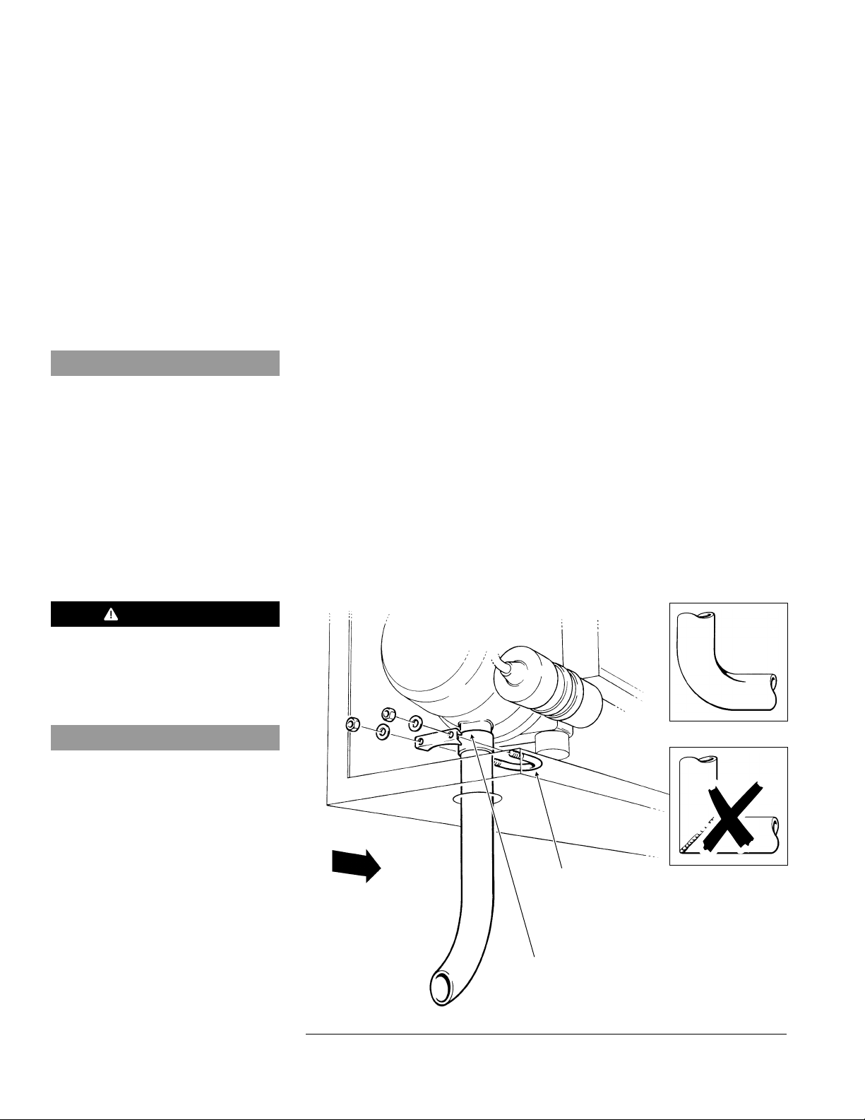
EXHAUST PIPE CONNECTION
1. Push the exhaust pipe through the hole in the enclosure and onto the
exhaust outlet port of the heater. Ensure that the pipe is pushed onto
the spigot at least 11⁄2" (38 mm).
2. Route the exhaust pipe such that:
• exhaust gasses do not enter the passenger compartment.
• exhaust gasses do not enter the heater's combustion air inlet
• exhaust system does not rest against or be directed toward any parts
of the vehicle that may be damaged by heat (i.e. brake lines, seals, wires
rubber hoses or bumpers). The exhaust pipe may be have to be insulated
if it's within 6" of combustible materials or composite body parts
• the exhaust outlet does not face the same direction as vehicle travel
• debris and snow will not plug the outlet
• the exhaust pipe is protected from curb damage
• the exhaust system should have a downwards slope for condensation
to drain. If needed a 3/8" hole should be drilled into the exhaust pipe
at the lowest point so that the condensation will drain.
3. Disassemble the exhaust pipe clamp and apply anti-seize compound to
the threads.
4. Assemble the exhaust clamp over the exhaust pipe (clamp goes inside
the enclosure) and tighten the nuts.
,
WARNING
Exhaust gases must not enter
the vehicle interior. Direct
exhaust pipe away from vehicle.
NOTICE
Use of muffler or other restrictions in the
exhaust system is not recommended.
NOTE: 11⁄2" exhaust pipe should not exceed 5 ft and have no more than
180 degrees of bends. The bends must be formed for best results.
Do not use 90 degree welded pipe to turn corners.
Use formed elbows.
Do not use welded
90˚ elbows.
DIRECTION
OF VEHICLE
TRAVEL
EXHAUST CLAMP
U BOLT (APPLY
ANTI-SEIZE
COMPOUND
TO THREADS)
3-6
ENSURE THERE ARE
NO AIR LEAKS AROUND
THE CONNECTION
Figure 3-11 Exhaust Pipe
PROHEAT INSTALLATION & SERVICE
3.4
PLUMBING THE SYSTEM
MA
X
I
MUM
C
ROS
S
-
F
Figure 3-12 Maximum cross-flow
3.4.1
L
OW
GENERAL CONSIDERATIONS
Coolant flow must be maintained throughout the coolant system
nder all conditions.
u
• Keep the engine inlet and outlet ports as far apart as possible to maximize
cross-flow through engine.
• Coolant pump and engine water pump must flow in the same direction.
• Ensure that no sharp kinks or bends exist in the hoses which may restrict
coolant flow.
• Avoid high points in the hose routing to prevent air traps.
• For systems requiring more than 50 feet of coolant line, contact Proheat
Product Support at www.proheat.com for coolant pump recommendations.
For plumbing the system use:
1
⁄2" NPT pipe fittings or bigger.
3
⁄4" ID heater hose.
NOTE: Use of silicone hose requires special hose clamps.
Shut-off valves are not required at the engine inlet and outlet connections but
may be used if desired. They should be left open at all times so that the heater
can be operated throughout the year.
You Choose
Select Your Plumbing Option
Option A:
Engine heat or supplemental heat.
The PROHEAT heats the engine block only.
NOTE: When the engine block is preheated you will have nearly
instant heat from the dash heat exchanger.
Option B: Engine and sleeper heat.
The PROHEAT heats the engine block and the sleeper.
NOTE: Plumbing the PROHEAT through the dash fan is not
recommended.
SECTION 3. INSTALLATION
3-7
Instructions for Options A and B
®®
WARNING
Opening the radiator cap when
the engine is hot may cause
serious injury.
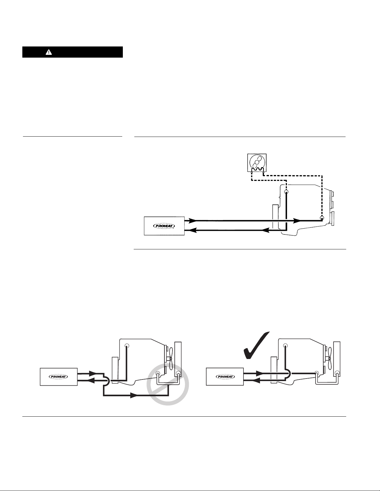
3.4.2
1. Remove the radiator cap to release the system pressure.
2. Drain the coolant system.
3. Plumb the system as per Figure 3-13 or Figure 3-15
. Add engine coolant to the system as per the specific engine
4
manufacturer’s recommendations and re-install the radiator cap.
NOTE: Plumbing the PROHEAT through the dash fan is not recommended.
OPTION A – Engine Heat or Supplemental Heat
DASH HEATER
RETURN TO ENGINE
RETURN TO ENGINE
SUPPLY TO PROHEAT
SUPPLY TO PROHEAT
Figure 3-13 Engine Heat or Supplemental Heat
ENGINE
NOTE: On coolant systems where the return from the PROHEAT is plumbed to
the bottom of the main coolant supply line from the radiator to engine
pump, the return line must be moved to avoid loss of heat through the
radiator.
ENGINE
RETURN TO ENGINE
SUPPLY TO PROHEAT
ENGINE
Figure 3-14 Correct Return Line Plumbing
3-8
PROHEAT INSTALLATION & SERVICE
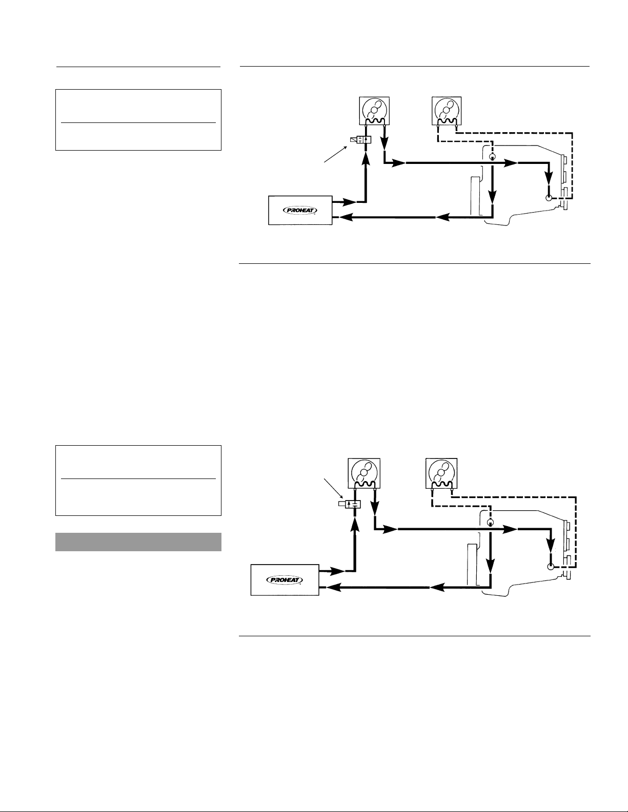
3.4.3
or best results these vehicles
F
should use an auxiliary heater.
International with single heater
OPTION B – Engine and Sleeper Heat
OEM OR AUXILIARY
SLEEPER HEATER
DASH HEATER
For vehicles with solenoid valves
in the normally closed position.
Western Star
SOLENOID VALVE
OEM COMBO HEATERS
ONLY (NORMALLY OPEN)
SUPPLY TO PROHEAT
Figure 3-15 Engine and Sleeper Heat
RETURN TO ENGINE
ENGINE
NOTE: Vehicles equipped with a combination heater/air-conditioner will have
a solenoid operated shut-off valve in the heater unit. Typically this valve
is normally open with the truck engine turned off and the key removed.
(See Figure 3-16 for plumbing)
Due to the many options available in vehicle heating and air
conditioning systems, the installer should be looking for any
restrictions that may affect coolant flow, with vehicle ignition in the
“OFF” position.
SLEEPER HEATER
SOLENOID VALVE
(NORMALLY CLOSED)
DASH HEATER
NOTICE
The PROHEAT PCM sleeper fan circuit
has a one minute delay during ignition.
Power to open a sleeper fan coolant
valve must be taken from another
source such as the wire for the hour
meter (auxiliary output). (See PROHEAT
Wiring Diagram on page 1-4.)
SECTION 3. INSTALLATION
SUPPLY TO PROHEAT
Figure 3-16 Engine and Sleeper Heat
RETURN TO ENGINE
ENGINE
3-9
 Loading...