

Page 1

G-II PCM SERVICE MANUAL
M50, M80/90 & M105/125
SE RIAL NUMBER S
G- II PCM MODEL HEATE RS: 705000 – TO DAT E
AN D ALL MODELS EQ UIPPED WITH A
G- II REPLACEMENT PCM
Rev. C
Page 2

CONTENTS
A. SAFETY .
SAFETY CONSIDERATIONS ..............................................................A-2
..................................................................................... A-1
B. INTRODUCTION ......................................................................... B-1
C. PROHEAT CONTROL MODULE (PCM) TYPE ............................ C-1
D. COMPRESSOR TYPE ................................................................ D-1
E. MODEL DESCRIPTIONS ............................................................ E-1
1.0 TECHNICAL SPECIFICATIONS.................................................. 1-1
1.1 PHYSICAL .............................................................................. 1-2
1.2 G-II PCM ELECTRICAL ............................................................. 1-8
1.3 TORQUE SPECIFICATIONS ....................................................... 1-9
2.0 PRINCIPLES OF OPERATION ................................................... 2-1
2.1 COMPONENT DESCRIPTION .................................................... 2-1
2.2 THEORY OF OPERATION .......................................................... 2-4
2.3 MODES OF OPERATION .......................................................... 2-6
2.3.1 Standard Mode............................................................2-6
2.3.2 Preheat Mode............................................................. 2-7
2.3.3 Supplemental Mode.................................................... 2-8
3.0 MAINTENANCE TOOLS ............................................................. 3-1
4.0 TROUBLESHOOTING AND REPAIR........................................... 4-1
4.1 SYSTEM AND COMPONENT DIAGNOSTICS................................ 4-2
4.1.1 EXAMPLE PROHEAT BEHAVIOR ERROR – Code 1 ........... 4-4
4.1.2 START Diagnostic Code 1............................................ 4-5
4.1.3 FLAME OUT Diagnostic Code 2 .................................. 4-23
4.1.4 COOLANT FLOW Diagnostic Code3 ............................. 4-24
4.1.5 OVERHEAT Diagnostic Code 4.................................... 4-25
4.1.6 VOLTAGE Diagnostic Code 5...................................... 4-26
4.1.7 FLAME FAULT Diagnostic Code 6 ............................... 4-27
4.1.8 TEMP SENSOR/COOLANT FLOW
Diagnostic Code 7 .................................................... 4-27
4.1.9 FUEL SOLENOID VALVE Diagnostic Code 8 ................. 4-29
4.1.10 NOT USED Diagnostic Code 9.................................... 4-29
4.1.11 IGNITION MODULE Diagnostic Code 10 ...................... 4-30
4.1.12 COOLANT PUMP Diagnostic Code 11.......................... 4-31
4.1.13 MOTOR Diagnostic Code 12 ...................................... 4-32
4.1.14 AUXILIARY OUTPUT Diagnostic Code 13 ..................... 4-34
4.1.15 ACCESSORY/SWITCH OUTPUT Diagnostic Code 14 ..... 4-34
4.1.16 INDICATOR OUTPUT Diagnostic Code 15 .................... 4-35
4.1.17 SYSTEM CURRENT Diagnostic Code 16...................... 4-35
4.1.18 MOTOR SPEED SENSOR Diagnostic Code 17 .............. 4-35
4.1.19 CANbus ERROR Diagnostic Code 18 .......................... 4-35
PROHEAT M-SERIES G-II PCM SERVICE MANUAL
i
Page 3

4.2 COMPONENT MECHANICAL OR ELECTRICAL PROBLEMS.......... 4-36
4.2.1 Fuel Nozzle .............................................................. 4-36
4.2.2 Fuel Solenoid Valve .................................................. 4-36
4.2.3 Fuel Regulator .......................................................... 4-36
4.2.4 Air Compressor......................................................... 4-36
4.2.5 Fuel Supply Pump ..................................................... 4-36
4.2.6 Ignition Electrodes .................................................... 4-36
4.2.7 G-II PCM Fuse........................................................... 4-36
4.3 OPERATIONAL PROBLEMS..................................................... 4-36
5.0 MAINTENANCE .......................................................................... 5-1
5.1 WEEKLY MAINTENANCE .......................................................... 5-1
5.2 ANNUAL MAINTENANCE .......................................................... 5-2
5.3
ROTARY VANE COMPRESSOR SERVICE & VANES INSTALLATION
.... 5-7
6.0 PROHEAT WARRANTY .............................................................. 6-1
ii
PROHEAT M-SERIES G-II PCM SERVICE MANUAL
Page 4

SAFETYA.
Throughout this manual, you will see notes labeled DANGER, WARNING,
CAUTION, and NOTICE to alert you to special instructions or precautions
concerning a particular procedure that would be hazardous if performed
incorrectly or carelessly.
Observe them carefully!
These safety alerts alone cannot eliminate all hazards. Strict compliance
with these special instructions and common sense are major accident
prevention measures.
DANGER
Immediate hazards that will result
in severe injury or death.
WARNING
Hazards or unsafe practices that
could result in severe personal
injury or death.
CAUTION
Hazards or unsafe practices that
could result in minor injury or
product or property damage.
NOTICE
Information that is important to
proper installation or maintenance,
but is not hazard-related.
PROHEAT M-SERIES G-II PCM SERVICE MANUAL
A-1
Page 5

SAFETY CONSIDERATIONS
WARNING
WARNING
WARNING
WARNING
WARNING
WARNING
Exhaust
Inhalation of exhaust gas (containing carbon monoxide) may cause severe personal
injury and/or death. Anyone suspected of suffering from CO inhalation should be
removed from the hazardous area and given medical assistance immediately.
Explosion Hazard
Do not operate heater where combustible fumes or airborne particles, such as sawdust, are present.
Fuel
Exercise extreme caution when working near fuel or fuel-filled equipment. Do not
operate heater during fueling operations. In addition, do not smoke or handle open
flame equipment, such as a blowtorch, around fuel.
Fire Hazard
Do not place any flammable items around the heater and exhaust pipe.
Batteries
Wear hand and eye protection when working near batteries. Do not smoke or use open
flames near batteries.
Electrical
Electric shock can cause severe personal injury, burns, and death. Before working on
any unit, disconnect the batteries. Use only approved materials and methods when
working on the electrical system and follow local electrical codes. Never work with
electricity in wet conditions or when you are feeling fatigued.
WARNING
WARNING
WARNING
DANGER
Poisons/Toxins
Fuel and coolant are toxic and in some cases, carcinogenic. Wear eye and hand
protection at all times. Remove contaminated clothing immediately and wash
contaminated skin. Do not breathe in vapors.
Moving/Hot Parts
Moving parts can cause severe injury and or death. Before working on any unit, shut it
off. Do not operate any unit until protective covers have been replaced. Always ensure
bolts and clamps are correctly torqued and secured. Inspect mechanical components
periodically for damage and corrosion.
Coolant
Never remove the filler cap when the engine is hot – escaping steam or scalding water
could cause serious personal injury. The coolant level in the expansion tank should be
checked at least weekly (more frequently in high mileage or arduous conditions). Always
check the level when the system is cold. Unscrew the filler cap slowly, allowing the
pressure to escape before removing completely. Never run the engine without coolant.
Prevent anti-freeze coming in contact with the skin or eyes. If this occurs, rinse
immediately with plenty of water. Anti-freeze will damage painted surfaces.
Never top-up with salt water. Even when travelling in territories where the water supply
contains salt, always ensure you carry a supply of fresh (rain or distilled) water.
California Proposition 65 Warning
Do not operate heater in garages or in other closed or unventilated areas.
Diesel exhaust and some of its constituents are known to the State of California to
cause cancer, birth defects, and other reproductive harm.
Electrical components in this product may contain lead, a chemical known to the
State of California to cause cancer and birth defects and other reproductive harm.
A-2
PROHEAT M-SERIES G-II PCM SERVICE MANUAL
Page 6
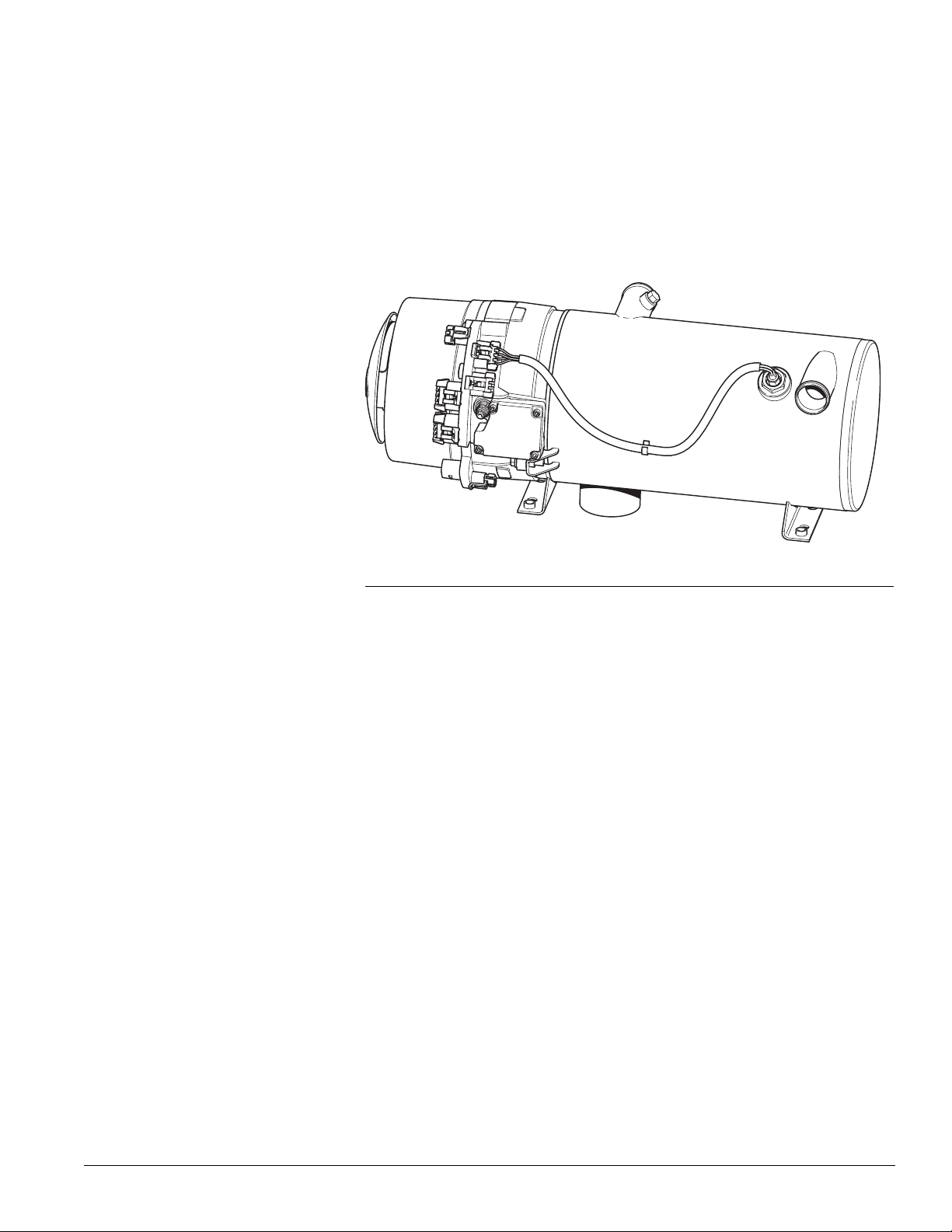
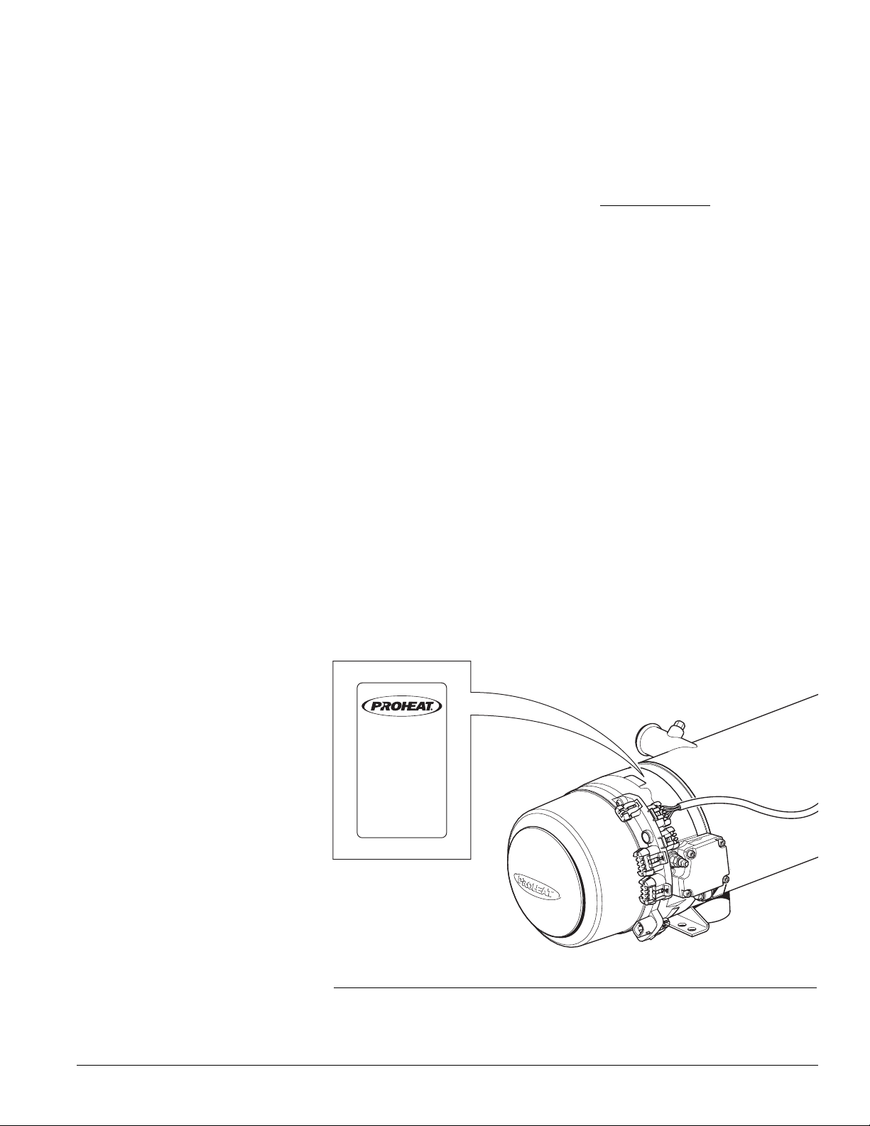
B.
INTRODUCTION
MODEL: M50, M80, M90,
M105, & M125 G-II PCM
Figure B-1.
This manual is provided to assist in troubleshooting and maintaining the
PROHEAT M-Series heater. They are designed for use on any diesel-equipped
vehicle including trucks, buses (school, transit and coach), construction
equipment, off road equipment, military equipment and cargo.
PROHEAT heaters are used for the following applications:
(1) Engine Block Heat – The PROHEAT will preheat an engine block to ensure
reliable starting in cold weather. Its’ use throughout the year will reduce
engine wear caused by cold starts.
(2) Supplemental Heat (engine running) – The PROHEAT can be used while
the vehicle is operating to provide supplemental heat for the engine
and/or passenger compartment.
(3) Cargo Heat – The PROHEAT can supply heat to individual compartments
as a stand-alone heating system, or it can provide supplemental heat to
an existing heating system.
(4) Marine – Marine applications typically involve the
installation of a complete hot-water
is only one component. SeaStar Solutions recommends that only an
expert in marine hot-water heating systems install a PROHEAT for
marine applications. NOTE: It is the
that an installation
complies with all applicable codes and regulations.
heating system of which PROHEAT
installer’s responsibility to ensure
engineering and
PROHEAT M-SERIES G-II PCM SERVICE MANUAL
B-1
Page 7

B-2
PROHEAT M-SERIES G-II PCM SERVICE MANUAL
Page 8

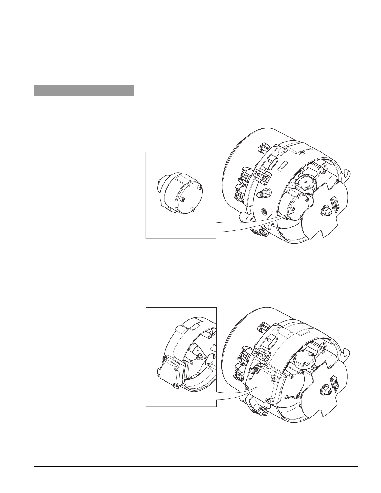
C.
G-I PCM G-II PCM
MET RI-PACK
1205264 4 AUX
CONNECTOR
KEYING
7 PIN
DATA LINK
CONNECTOR
FOUR PIN
DUAL MODE
TEMPERATURE
SENSOR
CONNECTOR
MET RI-PACK
12052641 A UX
CONNECTOR
KEYING
2 X TWO P IN
ANA LOG
TEMPERATURE
SENSOR
CONNECTORS
6 PIN
DATA LINK
CONNECTOR
NO AIR F ILTER
RET ENT ION
TANGS
AIR FILTER
RET ENT ION
TANGS
STATUS
INDICATOR
LIGHT
PROHEAT CONTROL
MODULE (PCM) TYPE
The G-I Proheat Control Module (PCM) is no longer available has been replaced
with the G-II PCM. The new G-II PCM incorporates a new dual mode analog/digital
temperature
identified in the figures below.
THIS MANUAL COVERS ONLY THE G-II PCM.
Please see G-I PCM Service Manual (M50/M80) part number
SL9150. This can be found by visiting www.proheat.com
sensor and advanced Data Link software. Both styles can be
Figure C-1. G-I PCM and G-II PCM.
PROHEAT M-SERIES G-II PCM SERVICE MANUAL
C-1
Page 9
DUAL MODE
TEMP SENSOR
S
TATUS
INDICATOR
LIGHT
DUAL MODE
HAS 4 PIN
CONNECTOR
G-II PCM
DUAL MODE
TEMP
SENSOR
ANALOG TEMP
SENSOR
NO STATUS
INDICATOR
LIGHT
ANALOG SENSOR
HAS 2 PIN
CONNECTOR
G-I PCM
ANALOG
TEMP
SENSOR
Figure C-2. G-II PCM can be identified on a heater by looking for the status indicator light.
Also the Dual Mode Temp Sensor has a 4 pin connector.
C-2
Figure C-3. G-I PCM can be identified on a heater by not having the status indicator light.
Also the Analog Temp Sensor has a 2 pin connector.
PROHEAT M-SERIES G-II PCM SERVICE MANUAL
Page 10
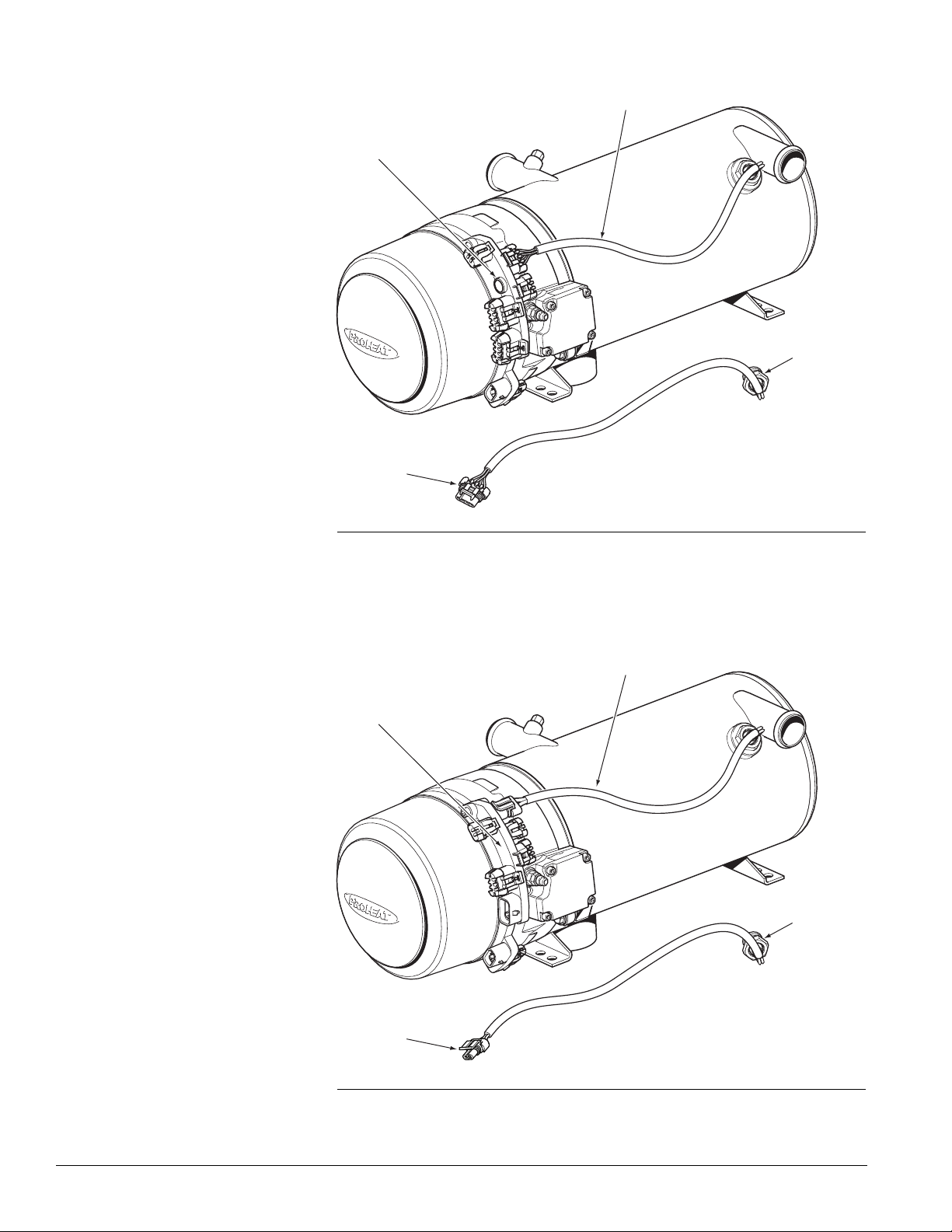
COMPRESSOR TYPED.
NOTICE
For continuity, all figures shown in this
manual will use a diaphragm compressor
unless
where special instructions or
illustrations
are required
.
The rotary vane compressor is no longer available has been replaced with the
diaphragm type. Both styles can be identified in the Figures below. Please refer
to the M-Series Parts Book at www.proheat.com for part numbers. This manual
covers both styles of compressors and clearly identifies the differences
where applicable.
ROTARY VANE COMPRESSOR
Serial Numbers:
500000 – 699999
Figure D-1. Rotary Vane Compressor Type.
DIAPHRAGM COMPRESSOR
Serial Numbers:
700000 – To Date
Figure D-2. Diaphragm Compressor Type.
PROHEAT M-SERIES G-II PCM SERVICE MANUAL
D-1
Page 11

D-2
PROHEAT M-SERIES G-II PCM SERVICE MANUAL
Page 12
MODEL : M80- 24V
S/ N: XXX XXX
POWER : 95 WATT S
FUEL TY PE: D IESEL
MAX PRE SS: 2 BAR
OPER. VOLT:
20-30 VDC
HEAT OUTPUT: 24.0 K
W
INSTALLATION DATE :
07 08 09 10 11 12
Made by SeaStar S olutions
Richmond B C Canada
PID 200101
MODEL DESCRIPTIONSE.
Please refer to the M-Series Parts Book at www.proheat.com for detailed part
descriptions and part numbers
such as a timer, coolant pump and associated installation equipment and
maintenance tools. The following information describes the general characteristics
of M-Series models covered in this manual: Heat Output, G-II PCM CANbus,
Voltage, Fuel Fitting optional configurations, and Air Intake optional configurations.
. Included in the parts book are optional features
Heat Output
G-II PCM
Voltage
The M Series is available in:
50,000 BTU/H (15 kW/H)
80,000 BTU/H (23 kW/H)
90,000 BTU/H (26 kW/H)
105,000 BTU/H (31 kW/H)
125,000 BTU/H (37 kW/H)
CANbus SAE J1939.
The M-Series G-II Proheat Control Module (G-II PCM) is available with CANbus
SAE J1939.
12 V or 24 V.
The M-Series is available in either a 12 V (10 – 15 VDC) or 24 V (20 – 30
VDC) model.
PROHEAT M-SERIES G-II PCM SERVICE MANUAL
Figure E-1.
E-1
Page 13
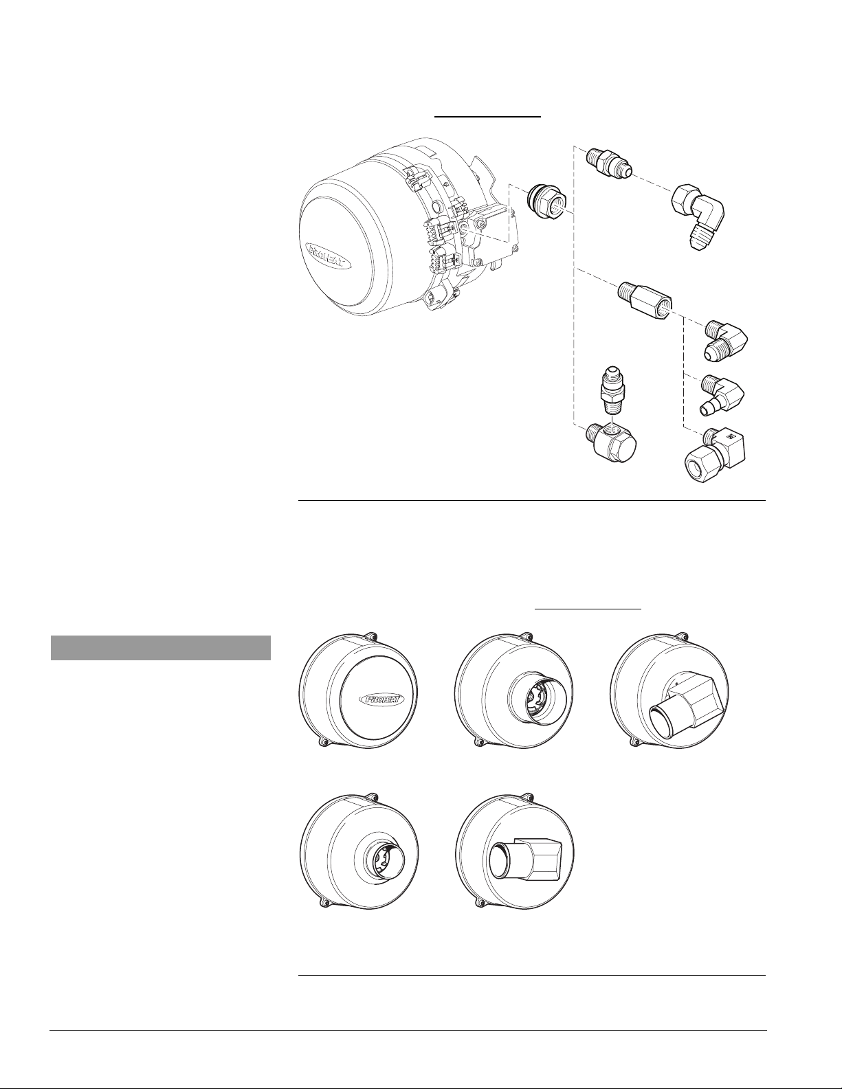
SPLASH GUARD STR AIGHT 3" OD
STR AIGHT SNORKEL
2.25" (55 mm) OD
SNORKEL ELBOW
26° SNORKEL ELBOW
Fuel Fitting – Optional
Configurations
-4 JIC, NPT 1/8” and -4 Hose Barb.
There are fuel fitting options including JIC, NPT, hose barb and tight access.
Refer to parts book at www.proheat.com.
Air Intake – Optional
Configurations
NOTICE
For continuity, all figures shown in this
manual
will use a splash guard intake.
Figure E-2.
Splash Guard, Straight and Right Angle Snorkel Attachments.
The M-Series can be equipped with a splash guard, straight and right angle
intake snorkels. Refer to parts book at www.proheat.com
E-2
Figure E-3. Air Intake Options.
PROHEAT M-SERIES G-II PCM SERVICE MANUAL
Page 14
1.0
TECHNICAL
SPECIFICATIONS
M50 12V M50 24V M80 12V M80 24V M90 24V
RATING BTU/hr (kW) 50,000 50,000 80,000 80,000 90,000 105,000 125,000
SYSTEM VOLTAGE 12 24 12 24 24 24 24
Nominal DC Voltage (Range) (10–15) (20–30) (10–15) (20–30) (20–30) (20–30) (20–30)
CURRENT DRAW (MAX) Amps 9.5 5.2 8.5 5.2 5.2 9.5 9.5
FUEL CONSUMPTION US gal/hr (L/hr) 0.48 0.48 0.78 0.78 0.82 1.05 1.10
IGNITION TYPE Electronic Spark Ignition
COOLANT OUTPUT TEMPERATURE MAX.
AMBIENT OPERATING TEMPERATURE
WEIGHT lbs (kg) 53 (24) 57.5 (26.1)
HEAT EXCHANGER CAPACITY US gal (l) 0.5 (2) 0.6 (2.3)
COOLANT SYSTEM
Minimum Capacity/Recommended Flow
Rate Through Heater US gpm (lpm) 7.5 (28) 7.5 (28) 12 (45) 12 (45) 13.2 (50) 15.8 (60) 18 (68)
Maximum Coolant Pressure PSI (bar) 29 (2) 29 (2) 29 (2) 29 (2) 29 (2) 29 (2) 29 (2)
DANGER
Do not use gasoline.
(15) (15) (23) (23) (26) (31) (37)
(1.8) (1.8) (2.95) (2.95) (3.10) (3.97) (4.16)
185°F (85°C)
-40°F to +122°F (-40°C to +50°C)
FUEL TYPES
COMPATIBLE Diesel (ULSD, #1, #2, Arctic), JP8, Jet A1
Bio Fuels - Contact Proheat www.proheat.com
M105 24V M125 24V
60 (27.2)
0.7 (2.6)
SYSTEM OUTPUTS
AUXILIARY OUTPUT Same as Power Supply Voltage
SWITCH/TIMER Same as Power Supply Voltage
POWER Maximum 1 Amp draw (over-load shut-off protection)
COOLANT PUMP Same as Power Supply Voltage
INDICATOR LIGHT Same as Power Supply Voltage
SWITCH Same as Power Supply Voltage
COOLANT PUMP Same as Power Supply Voltage
AUXILIARY Allows independent operation of Coolant Pump through
POWER 12 Volt or 24 Volt
Maximum 1 Amp draw (over-load shut-off protection)
High-side switched
High-side switched
Maximum 10 Amp draw (over-load shut-off protection)
High-side switched
Maximum 1 Amp draw (over-load shut-off protection)
High-side switched
SYSTEM INPUTS
Standard Run Mode
Preheat Run Mode
Supplemental Run Mode
the G-II Proheat Control Module
PROHEAT M-SERIES G-II PCM SERVICE MANUAL
1-1
Page 15
EXHAUST
(SEE NOTE 2 AND 4)
-4 JIC MALE FUEL INLET (INTERNAL
FUEL FILTER) (SEE NOTE 5)
2.75 (70)
12.60 (320)
23.24 (590)
4.45
(113)
8.14 (207)
2.03 (52)
FRONT VIEW
6 x .41 (10)
BOTTOM VIEW
AIR INTAKE
ALTERNATE
SNORKELS
AVAILABLE
(SEE PAGE 1-3 )
3.23 (82)
3.98
(101)
SIDE VIEW
SERVICE SPACE REQUIREMENT
(
MAY VARY SEE NOTE 3 & PAGE 1-3)
G-II
PCM
5.39
(137)
8.58
(218)
7.63
(194)
REAR VIEW
4.33
(110)
5.90
(150)
4 x M8 x 1.25 MOUNTING PEM NUTS
HEAT EXCHANGER
(SEE NOTE 6)
.75 (19)
10.13 (257)
9.00 (229)
5.77
(147)
DUAL MODE TEMPERATURE
SENSOR
9
.55 (243)
TOP VIEW
COOL AN T INLET
COOL AN T OUTLET
2 x 1.50 (38)
1
.97 (50)
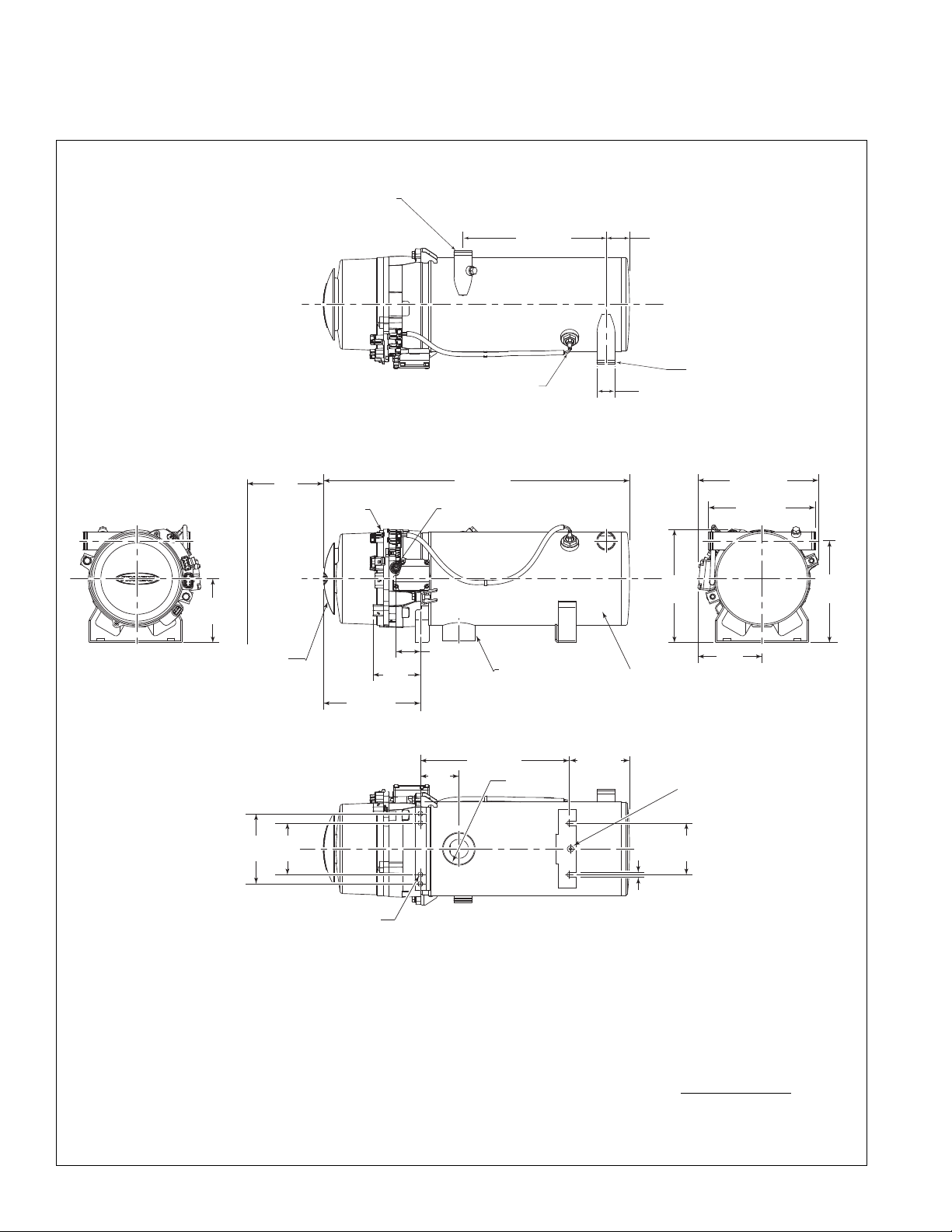
PHYSICAL – M50/M801.1
NOTES:
1. DIMENSIONS ARE IN INCHES (MILLIMETERS IN BRACKETS).
2. TYPICAL EXHAUST CUTOUT 3.25" CENTERED ON EXHAUST.
3. SERVICE SPACE REQUIRED TO REMOVE BURNER HEAD AND
COMBUSTION TUBE FOR PERIODIC INSPECTION AND CLEANING.
4. THE EXHAUST PIPE SHOULD HAVE A MINIMUM DIAMETER OF
2.75", A MAXIMUM LENGTH OF 5' AND HAVE NO MORE THAN
180° OF BENDS.
5. ALTERNATE FUEL INLET CONFIGURATIONS AVAILABLE, SEE
PARTS BOOK FOR FURTHER INFORMATION.
6. ALTERNATE HEAT EXCHANGERS AVAILABLE, SEE PARTS BOOK
FOR FURTHER INFORMATION.
7. SNORKEL HOSE REQUIRED FOR THIS AIR INTAKE OPTION.
CONTACT TECH SUPPORT AT WWW.PROHEAT.COM FOR
LENGTH AND BEND RESTRICTIONS.
1-2
PROHEAT M-SERIES G-II PCM SERVICE MANUAL
Page 16
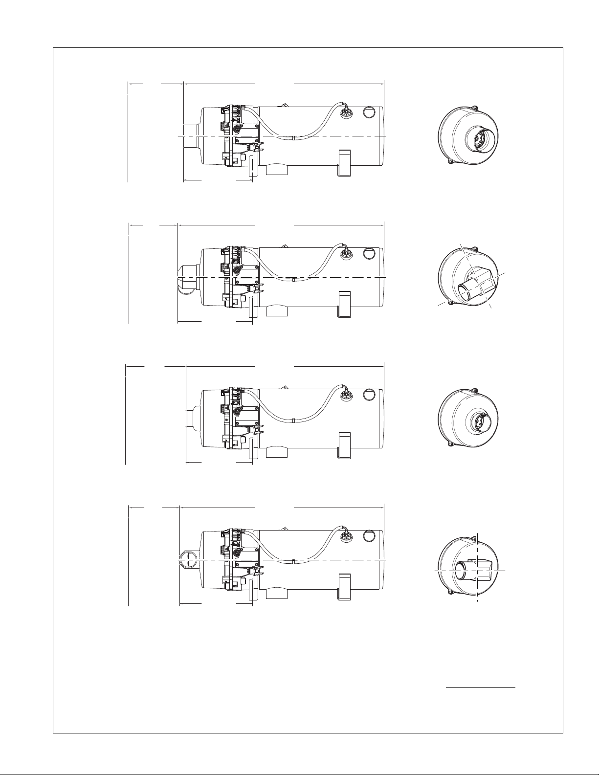
A
IR INTAKE OPTION:
3" OD SNORKEL SEE NOTE 7
AIR INTAKE OPTION:
2
.25" OD ELBOW WITH 26° ADAPTER PLATE
S
EE NOTE 7
CAN BE INSTALLED AT: 26°, 116°, 206°, 296°
AIR INTAKE OPTION:
2.25" OD SNORKEL SEE NOTE 7
AIR INTAKE OPTION: 2.25" OD ELBOW SEE NOTE 7
CAN BE INSTALLED AT 0°, 90°, 180°, 270°
2
4.31 (617
)
4
.71
(
120
)
SERVICE
SPACE
REQUIREMENT
(SEE NOTE 3)
9.21 (234)
2
9.09 (637
)
3
.93
(
100
)
SERVICE
SPACE
REQUIREMENT
(SEE NOTE 3)
9.99 (254)
24.00 (610)
5.20
(132
)
SERVICE
SPACE
REQUIREMENT
(SEE NOTE 3)
8.90 (226)
24.80 (630)
4.22
(107)
SERVICE
SPACE
REQUIREMENT
(SEE NOTE 3)
9.70 (246)
90°
0°
270°
180°
1
16°
26°
296°
206°
NOTES:
1. DIMENSIONS ARE IN INCHES (MILLIMETERS IN BRACKETS).
2. TYPICAL EXHAUST CUTOUT 3.25" CENTERED ON EXHAUST.
3. SERVICE SPACE REQUIRED TO REMOVE BURNER HEAD AND
COMBUSTION TUBE FOR PERIODIC INSPECTION AND CLEANING.
4. THE EXHAUST PIPE SHOULD HAVE A MINIMUM DIAMETER OF
2.75", A MAXIMUM LENGTH OF 5' AND HAVE NO MORE THAN
180° OF BENDS.
5. ALTERNATE FUEL INLET CONFIGURATIONS AVAILABLE, SEE
PARTS BOOK FOR FURTHER INFORMATION.
6. ALTERNATE HEAT EXCHANGERS AVAILABLE, SEE PARTS BOOK
FOR FURTHER INFORMATION.
7. SNORKEL HOSE REQUIRED FOR THIS AIR INTAKE OPTION.
CONTACT TECH SUPPORT AT WWW.PROHEAT.COM FOR
LENGTH AND BEND RESTRICTIONS.
PROHEAT M-SERIES G-II PCM SERVICE MANUAL
1-3
Page 17
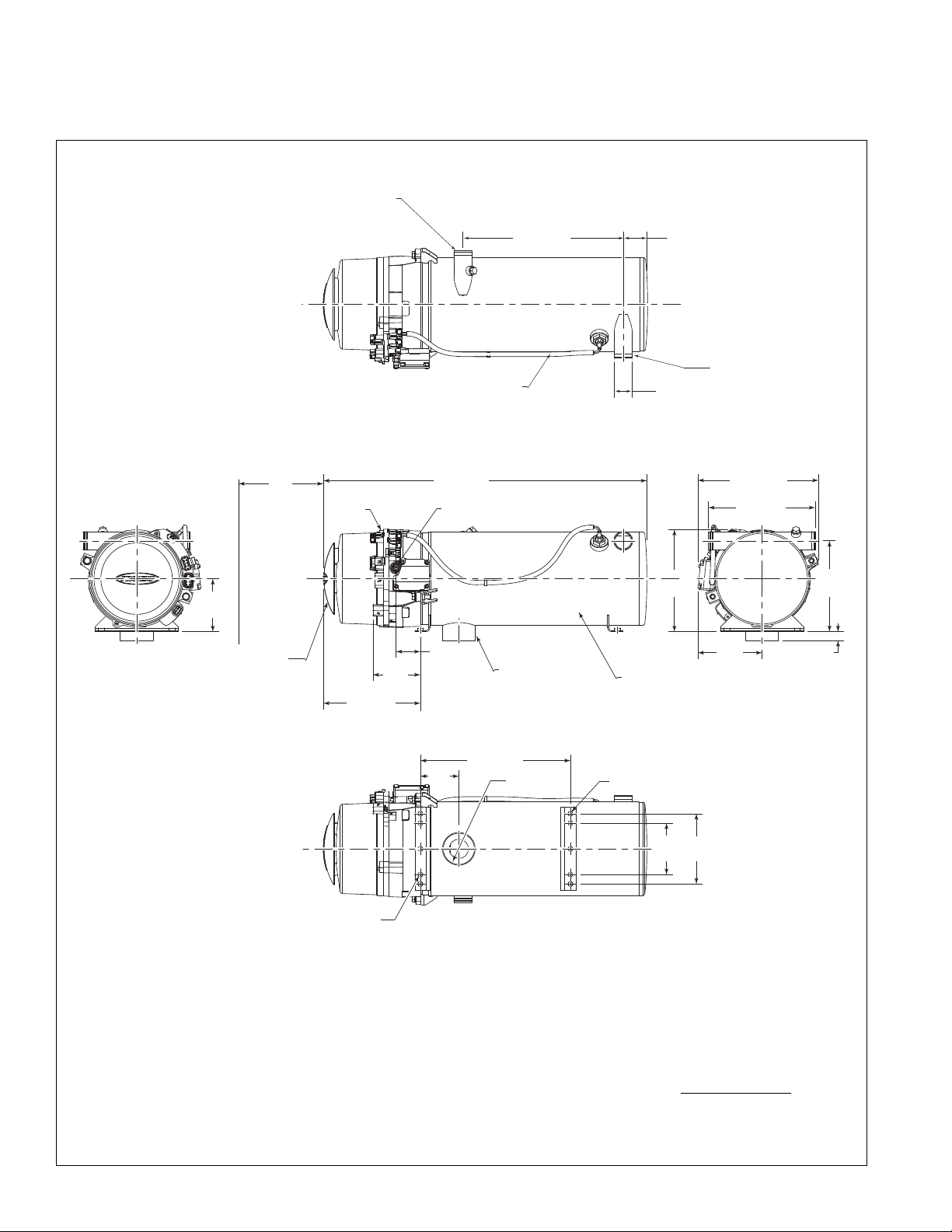
EXHAUST
(SEE NOTE 2 AND 4)
-4 JIC MALE FUEL INLET (INTERNAL
FUEL FILTER) (SEE NOTE 5)
2.75 (70)
12.60 (320)
25.74 (654)
5.37
(136)
8.14 (207)
2.03 (52)
FRONT VIEW
2 x .394 (10)
BOTTOM VIEW
AIR INTAKE
ALTERNATE
SNORKELS
AVAILABLE
(SEE PAGE 1-3 )
3.22 (82)
5.00 (27)
3.98
(101)
SIDE VIEW
SERVICE SPACE REQUIREMENT
(
MAY VARY SEE NOTE 3 & PAGE 1-3)
G-II
PCM
5.39
(137)
9.5
(241)
8.55
(217)
REAR VIEW
4.33
(110)
4.33
(110)
5.91
(150)
.394
(10)
3 x M8 x 1.25
HEAT EXCHANGER
(SEE NOTE 6)
10.13 (257)
9.00 (229)
8.25
(210)
DUAL MODE TEMPERATURE
SENSOR
1
2.05 (306)
TOP VIEW
COOL AN T INLET
COOL AN T OUTLET
2 x 1.50 (38)
1
.97 (50)
PHYSICAL – M90/105
NOTES:
1-4
1. DIMENSIONS ARE IN INCHES (MILLIMETERS IN BRACKETS).
2. TYPICAL EXHAUST CUTOUT 3.25" CENTERED ON EXHAUST.
3. SERVICE SPACE REQUIRED TO REMOVE BURNER HEAD AND
COMBUSTION TUBE FOR PERIODIC INSPECTION AND CLEANING.
4. THE EXHAUST PIPE SHOULD HAVE A MINIMUM DIAMETER OF
2.75", A MAXIMUM LENGTH OF 5' AND HAVE NO MORE THAN
180° OF BENDS.
5. ALTERNATE FUEL INLET CONFIGURATIONS AVAILABLE, SEE
PARTS BOOK FOR FURTHER INFORMATION.
6. ALTERNATE HEAT EXCHANGERS AVAILABLE, SEE PARTS BOOK
FOR FURTHER INFORMATION.
7. SNORKEL HOSE REQUIRED FOR THIS AIR INTAKE OPTION.
CONTACT TECH SUPPORT AT WWW.PROHEAT.COM FOR
LENGTH AND BEND RESTRICTIONS.
PROHEAT M-SERIES G-II PCM SERVICE MANUAL
Page 18
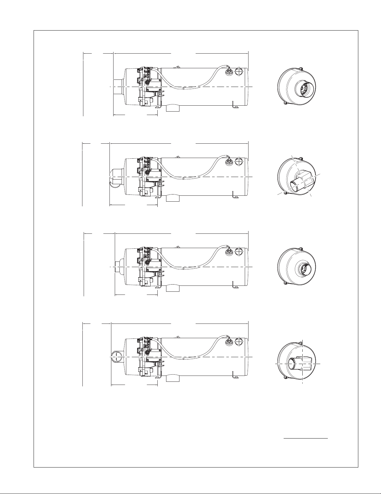
A
IR INTAKE OPTION:
3" OD SNORKEL SEE NOTE 7
AIR INTAKE OPTION:
2
.25" OD ELBOW WITH 26° ADAPTER PLATE
S
EE NOTE 7
CAN BE INSTALLED AT: 26°, 116°, 206°, 296°
AIR INTAKE OPTION:
2.25" OD SNORKEL SEE NOTE 7
AIR INTAKE OPTION: 2.25" OD ELBOW
SEE NOTE 7
CAN BE INSTALLED AT 0°, 90°, 180°, 270°
2
6.81 (681
)
7
.21
(
183
)
SERVICE
SPACE
REQUIREMENT
(SEE NOTE 3)
9.21 (234)
3
1.59 (802
)
6
.43
(
163
)
SERVICE
SPACE
REQUIREMENT
(SEE NOTE 3)
9.99 (254)
26.50 (673)
7.70
(196
)
SERVICE
SPACE
REQUIREMENT
(SEE NOTE 3)
8.90 (226)
27.30 (693)
6.72
(171)
SERVICE
SPACE
REQUIREMENT
(SEE NOTE 3)
9.70 (246)
90°
0°
270°
180°
1
16°
26°
296°
206°
NOTES:
1. DIMENSIONS ARE IN INCHES (MILLIMETERS IN BRACKETS).
2. TYPICAL EXHAUST CUTOUT 3.25" CENTERED ON EXHAUST.
3. SERVICE SPACE REQUIRED TO REMOVE BURNER HEAD AND
COMBUSTION TUBE FOR PERIODIC INSPECTION AND CLEANING.
4. THE EXHAUST PIPE SHOULD HAVE A MINIMUM DIAMETER OF
2.75", A MAXIMUM LENGTH OF 5' AND HAVE NO MORE THAN
180° OF BENDS.
5. ALTERNATE FUEL INLET CONFIGURATIONS AVAILABLE, SEE
PARTS BOOK FOR FURTHER INFORMATION.
6. ALTERNATE HEAT EXCHANGERS AVAILABLE, SEE PARTS BOOK
FOR FURTHER INFORMATION.
7. SNORKEL HOSE REQUIRED FOR THIS AIR INTAKE OPTION.
CONTACT TECH SUPPORT AT WWW.PROHEAT.COM FOR
LENGTH AND BEND RESTRICTIONS.
PROHEAT M-SERIES G-II PCM SERVICE MANUAL
1-5
Page 19
EXHAUST
(SEE NOTE 2 AND 4)
-4 JIC MALE FUEL INLET (INTERNAL
FUEL FILTER) (SEE NOTE 5)
2.75 (70)
12.60 (320)
27.24 (692)
4.45
(113)
8.14 (207)
2.03 (52)
FRONT VIEW
6 x .41 (10)
BOTTOM VIEW
AIR INTAKE
ALTERNATE
SNORKELS
AVAILABLE
(SEE PAGE 1-3 )
3.23 (82)
3.98
(101)
SIDE VIEW
SERVICE SPACE REQUIREMENT
(
MAY VARY SEE NOTE 3 & PAGE 1-3)
G-II
PCM
5.39
(137)
8.58
(218)
7.63
(194)
REAR VIEW
4.33
(110)
5.90
(150)
4 x M8 x 1.25 MOUNTING PEM NUTS
HEAT EXCHANGER
(SEE NOTE 6)
.75 (19)
10.13 (257)
9.00 (229)
9.78
(248)
DUAL MODE TEMPERATURE
SENSOR
1
3.55 (3 44)
TOP VIEW
COOL AN T INLET
COOL AN T OUTLET
2 x 1.50 (38)
1
.97 (50)
PHYSICAL – M125
NOTES:
1. DIMENSIONS ARE IN INCHES (MILLIMETERS IN BRACKETS).
2. TYPICAL EXHAUST CUTOUT 3.25" CENTERED ON EXHAUST.
3. SERVICE SPACE REQUIRED TO REMOVE BURNER HEAD AND
COMBUSTION TUBE FOR PERIODIC INSPECTION AND CLEANING.
4. THE EXHAUST PIPE SHOULD HAVE A MINIMUM DIAMETER OF
2.75", A MAXIMUM LENGTH OF 5' AND HAVE NO MORE THAN
180° OF BENDS.
5. ALTERNATE FUEL INLET CONFIGURATIONS AVAILABLE, SEE
PARTS BOOK FOR FURTHER INFORMATION.
6. ALTERNATE HEAT EXCHANGERS AVAILABLE, SEE PARTS BOOK
FOR FURTHER INFORMATION.
7. SNORKEL HOSE REQUIRED FOR THIS AIR INTAKE OPTION.
CONTACT TECH SUPPORT AT WWW.PROHEAT.COM FOR
LENGTH AND BEND RESTRICTIONS.
1-6
PROHEAT M-SERIES G-II PCM SERVICE MANUAL
Page 20
A
IR INTAKE OPTION:
3" OD SNORKEL SEE NOTE 7
A
IR INTAKE OPTION: 2.25" OD ELBOW
WITH 26° ADAPTER PLATE
SEE NOTE 7
C
AN BE INSTALLED AT:
26°, 116°, 206°, 296°
AIR INTAKE OPTION:
2.25" OD SNORKEL SEE NOTE 7
AIR INTAKE OPTION: 2.25" OD
ELBOW SEE NOTE 7
CAN BE INSTALLED AT:
0°, 90°, 180°, 270°
2
8.31 (719
)
8
.71
(
221
)
SERVICE
SPACE
REQUIREMENT
(SEE NOTE 3)
9.21 (234)
3
3.09 (840
)
7
.93
(
201
SERVICE
SPACE
REQUIREMENT
(SEE NOTE 3)
9.99 (254)
28.00 (711)
9.02
(22.9
)
SERVICE
SPACE
REQUIREMENT
(SEE NOTE 3)
8.90 (226)
28.80 (732)
8.22
(209)
SERVICE
SPACE
REQUIREMENT
(SEE NOTE 3)
9.70 (246)
90°
0°
270°
180°
1
16°
26°
296°
206°
NOTES:
1. DIMENSIONS ARE IN INCHES (MILLIMETERS IN BRACKETS).
2. TYPICAL EXHAUST CUTOUT 3.25" CENTERED ON EXHAUST.
3. SERVICE SPACE REQUIRED TO REMOVE BURNER HEAD AND
COMBUSTION TUBE FOR PERIODIC INSPECTION AND CLEANING.
4. THE EXHAUST PIPE SHOULD HAVE A MINIMUM DIAMETER OF
2.75", A MAXIMUM LENGTH OF 5' AND HAVE NO MORE THAN
180° OF BENDS.
PROHEAT M-SERIES G-II PCM SERVICE MANUAL
5. ALTERNATE FUEL INLET CONFIGURATIONS AVAILABLE, SEE
PARTS BOOK FOR FURTHER INFORMATION.
6. ALTERNATE HEAT EXCHANGERS AVAILABLE, SEE PARTS BOOK
FOR FURTHER INFORMATION.
7. SNORKEL HOSE REQUIRED FOR THIS AIR INTAKE OPTION.
CONTACT TECH SUPPORT AT WWW.PROHEAT.COM FOR
LENGTH AND BEND RESTRICTIONS.
1-7
Page 21
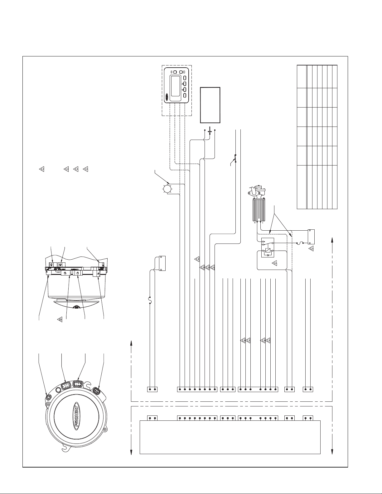
G-II PCM ELECTRICAL1.2
PROHEAT G-II PCM
INDIC ATOR OUTP UT (HIGH SI DE SWITCH ED. DASH OR PR OHEAT TOGG LE SWITC H LIGHT) (1 A MP MAX)
POWE R OUTPUT (C ONSTANT P OWER. TIM ER/SWI TCH REMO TE PANEL) (1 A MP MAX SH ARED WIT H P3-E)
MAI N SWITCH IN PUT (STAND ARD "ON" S IGNAL OR PR EHEAT UNL ATCH) – AC TIVE HIGH
BB
GROUN D (INDICAT OR GROUND) (1 AM P MAX)
UNUSE D
ACCE SSORY POW ER OUTPU T (1 AMP MA X)
USBD + (I /O) – SEE NOT E 6
USBD - (I /O) – SEE NOT E 6
COOL ANT PUMP O UTPUT GR OUND (10 AMP MA X)
COOL ANT PUMP O UTPUT (10 A MP MAX)
USB GRO UND – SEE NOT E 6
GROUN D (ACCESS ORY OUTPU T GROUND) (1 AM P MAX)
PREH EAT SWITC H INPUT – AC TIVE HIGH
SUPP LEMENTA L SWITCH IN PUT – ACTI VE HIGH
PUMP (C OOLANT ) SWITCH I NPUT – ACT IVE HIGH
P4
COOLANT
PUMP
OUTPUT
PROHEAT PCM
B
A
B
A
P3
DATALINK
F FCE
B
A
CEB
A
P2
CONTROL
GG
H H
F
ECD
F
ECD
O.E.M. SUPPLIED
BATT ERY POSI TIVE (FUS E/BRE AKER 30 A MP)
BATT ERY NEGAT IVE (GROUN D)
P1
POWER
A A
B
A
B
A
PROHEAT PCM
FUSE
30 AMP
P5 - AUX (OUTPUT)
METRI-PACK
150 SERIES, 2 PIN
ENGINE RUN (ALTERNATOR SIGNAL)
SIGNAL FROM OEM HEATING SYSTEM
TO TURN ON COOLANT PUMP WHEN
REQUIRED FOR A REASON OTHER
THAN WHEN THE HEATER REQUIRES
THE PUMP.
MECHANICS DISABLE
SWITCH MOUNTED IN A
PROTECTED LOCATION
O.E.M. SUPPLIED
OFF
ON
SPRING CENTERED
DOUBLE THROW
MOMENTARY SWITCH.
LOCATED ON THE
DRIVERS CONSOLE.
NOTES:
1/ WIRE MUST MEET OR EXCEED SAE J1128 GLX SPECIFICATIONS.
2/ ALL WIRE AND INSULATION THICKNESSES TO MATCH THOSE
SPECIFIED BY DELPHI FOR THE GIVEN PART NUMBERS IN TABLE 1
3/ ALL UNUSED CONNECTIONS ON THE PCM ARE SUPPLIED
WITH CONNECTOR PLUGS ON STANDARD HEATERS.
4/ ALL CONTROL SIGNAL INPUT VOLTAGES MUST MATCH
HEATER SUPPLY VOLTAGE.
5/ ALL HEATER OUTPUT SIGNALS WILL MATCH HEATER
SUPPLY VOLTAGE.
6/ WIRE USED ON DATALINK CONNECTOR USB CONNECTIONS
(P3) MUST MEET UNIVERSAL SERIAL BUS CABLES AND
CONNECTION STANDARDS REV 2.0. USB WIRES MAXIMUM
LENGTH IS 13.1FT (4M).
RED
GREEN
WHITE
BLACK
TIMER OPTION TI* OR TII
INDICATOR
LIGHT
LOCATED AS PER
CUSTOMER REQUEST OR
OEM REQUIREMENT
SHIEL D
CAN- L
CAN- H
P6
CAN BUS
C
B
C
B
A A
AUX ILIARY OU TPUT (HIG H SIDE SWIT CHED) (1 AMP M AX)
AUX ILIARY OU TPUT GROU ND (AUXIL IARY OUT PUT) (1 AM P MAX)
P5
AUXILIARY
OUTPUT
B
A
B
A
H
G
UNUSE D
USB PO WER – SEE NOT E 6
H
G
VEHICLE BATTERY
OPTIONALLY, PUMP CAN BE CONNECTED DIRECTTLY
TO PCM (10 AMP MAX CURRENT DRAW)
FUSE
*TI TIMER REQUIRES HARNESS PID: 200100
VEHICLE BATTERY
LOCK
PART#
12052634
12066304
12066304
15300014
PCM
CONNECTOR
P4-PUMP (COOLANT)
P3-DATALINK(DOWNLOAD)
P2-CONTROL (SWITCH)
P1-POWER
12047937
12052641
12047938
CONNECTOR
PART#
15300027
CAVITY PLUG
PART#
1205916812048074 12048086
12048086
12048086
12048074
12048074
----
12059168
WIRE SEAL
PART#
12015193
TERMINAL
PART#
12077413
----
P5-AUXILIARY
P6-CAN BUS
12052644
12110293
12052634
12052845
12048074
12048074
12048086
12048086
----
----
TABLE 1: CONNECTOR ASSEMBLY PART NUMBERS
+
–
+
–
COOLANT PUMP
86 30
85
87a 87
COOLANT
PUMP
RELAY
+ –
CLOCK
TIME
DAY
TIMER
THERMALSYSTEMS
MANUAL
P6 - CANBUS (OPTIONAL)
METRI-PACK 150 SERIES,
3-PIN
P7 - DUAL MODE TEMP
SENSOR
P4 - PUMP (COOLANT)
METRI-PACK 150 SERIES,
2 PIN
P3 - DATALINK
(DOWNLOAD)
METRI-PACK
150 SERIES, 7 PIN
P2 - CONTROL (SWITCH)
METRI-PACK
150 SERIES, 8 PIN
P1 - POWER
METRI-PACK
280 SERIES, 2 PIN
1-8
PROHEAT M-SERIES G-II PCM SERVICE MANUAL
Page 22
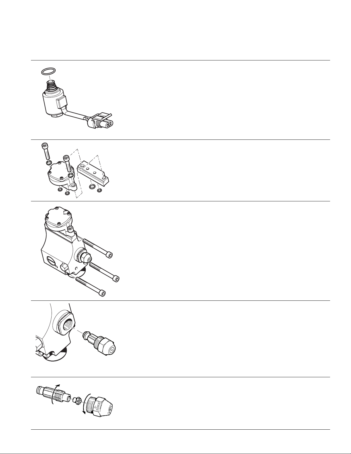
TORQUE SPECIFICATIONS1.3
Solenoid Valve
• Lubricate O-ring with diesel fuel.
• Install solenoid valve by hand.
• Ensure poppet and spring remain in place during assembly.
• Torque solenoid valve to fuel block to 25 in. lbs. ± 3 in. lbs.
(2.8 Nm ± 0.3 Nm).
Regulator
• Install 2 o-rings on back side of regulator.
• Torque screws (2) to 75 in. lbs. ± 3 in. lbs. (8.5 Nm ± 0.3 Nm).
Fuel Delivery Block
• Ensure all three O-rings are in place.
• Torque screws (3) to 75 in. lbs. ± 7 in. lbs. (8.5 Nm ± 0.8 Nm).
Nozzle
• Lubricate O-ring on nozzle with diesel fuel.
• Torque nozzle to fuel block to 150 in. lbs. ± 10 in. lbs.
(16.9 Nm ± 1.1 Nm).
PROHEAT M-SERIES G-II PCM SERVICE MANUAL
Nozzle Assembly
• Torque nozzle to nozzle stem to 30 in. lbs. ± 3 in. lbs. (3.4Nm ± .3 Nm).
1-9
Page 23
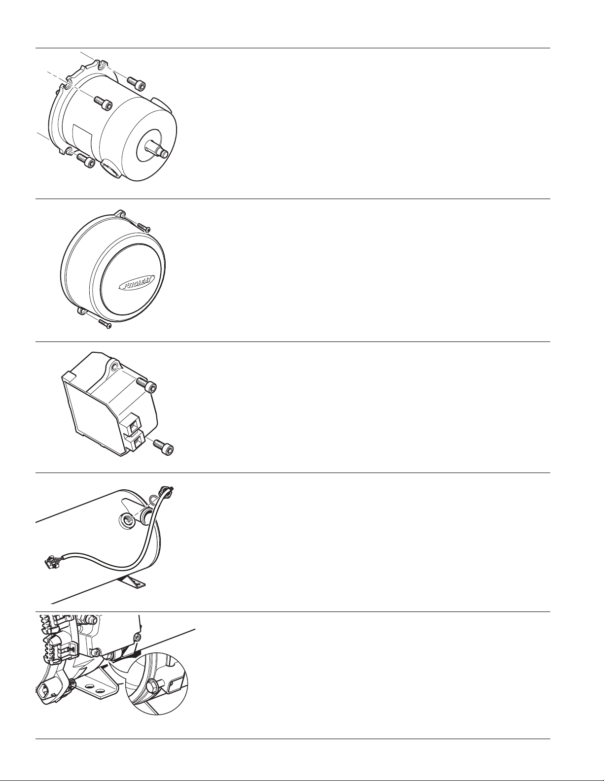
Motor
• Rotate motor shaft until motor drops into fuel pump gear.
• Ensure correct alignment (refer to ‘Motor Replacement’ on page 4-33)
Torque bolts (4) to 75 in. lbs. ± 7 in. lbs. (8.5 Nm ± 0.8 Nm).
•
Blower Housing
• Torque bolts (2) to 75 in. lbs. ± 7 in. lbs. (8.5 Nm ± 0.8 Nm).
Ignition Module
• Torque screws (2) to 75 in. lbs. ± 7 in. lbs. (8.5 Nm ± 0.8 Nm).
Dual Mode Temperature Sensor
• Install O-ring onto sensor.
• Torque sensor to 100 in. lbs. ± 10 in. lbs. (11.6 Nm ± 1.1 Nm).
Burner Head/Heat Exchanger
• Torque bolts (2) to 100 in. lbs. ± 10 in. lbs. (11.6 Nm ± 1.1 Nm).
1-10
PROHEAT M-SERIES G-II PCM SERVICE MANUAL
Page 24
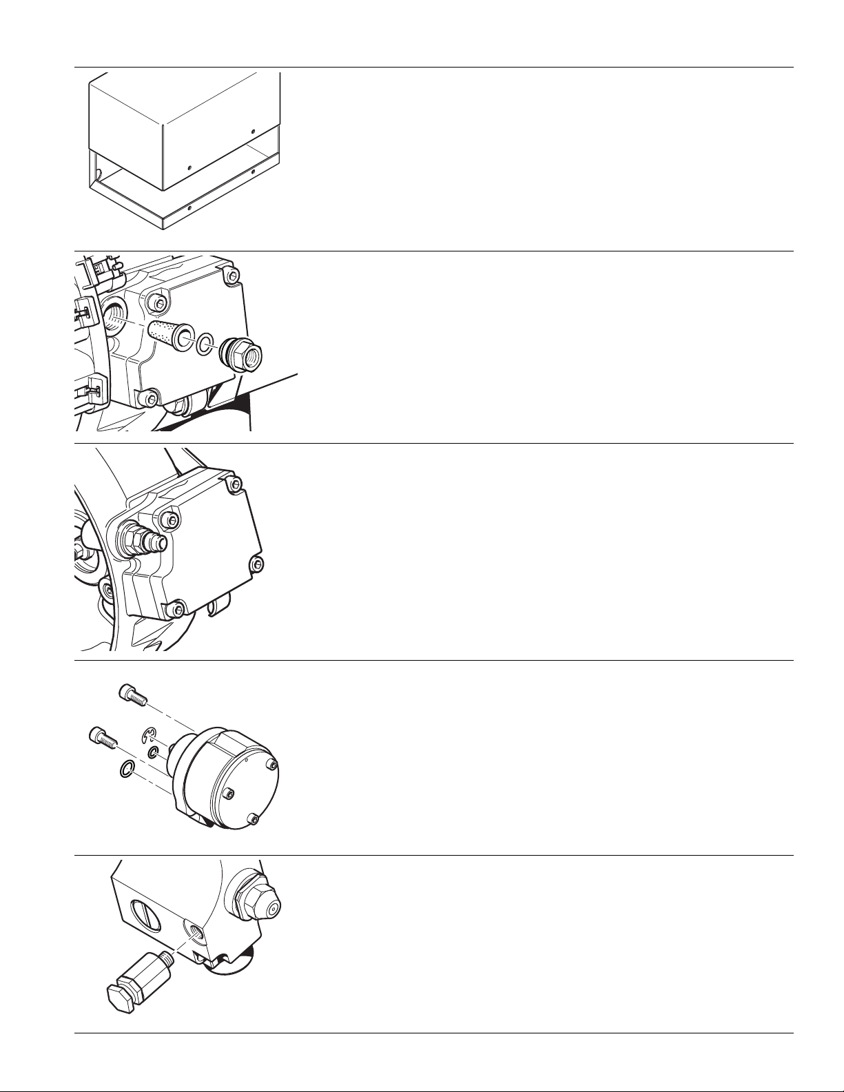
Enclosure Lid (Optional)
• Torque screws (4) to 100 in. lbs. ± 10 in. lbs. (11.6 Nm ± 1.1 Nm).
Fuel Filter Fitting
• Install O-ring onto fitting.
• Torque fitting to 100 ± 10 in. lbs. (11.3 ± 1.1 Nm).
Diaphragm Compressor ONLY
Serial Numbers 70000 and above
• Install O-rings in to cylinder head and valve cover (not shown).
• Ensure connecting rod is at BDC and ensure the diaphragm is concentric
to the diaphragm opening (not shown).
• Torque to 27 in. lbs +/- 3 in. lbs using a crisscross pattern.
Rotary Vane Compressor ONLY
Serial Numbers 500000 – 699999
• Install O-rings into burner flange.
• Install compressor into burner flange. (Ensure correct alignment—refer to
Compressor Replacement’ on page 5-7.)
• Torque screws (2) to 75 in. lbs. ± 3 in. lbs. (8.5 Nm ± 0.3 Nm).
Relief Valve
– for Use with Rotary Vane Compressor ONLY
PROHEAT M-SERIES G-II PCM SERVICE MANUAL
Serial Numbers 600000 – 699999
• Torque to 25 in. lbs. ± 3 in. lbs. (2.8 Nm ± 0.3 Nm).
1-11
Page 25

1-12
PROHEAT M-SERIES G-II PCM SERVICE MANUAL
Page 26

2.0
PRINCIPLE OF
OPERATION
2.1
Combustion Air Blower:
Motor:
Fuel Supply Pump:
Fuel Regulator:
Fuel Nozzle:
COMPONENT DESCRIPTIONS
Impeller-style blower driven by the Motor provides the principle combustion air.
Drives the Combustion Air Blower, Air Compressor and Fuel Supply Pump.
A positive displacement, gear-type pump that draws fuel from the vehicle fuel
tank and supplies it to the Fuel Regulator. Pressure is regulated between
5 – 10 PSI by means of an internal relief valve. Fuel is re-circulated within the
pump, therefore a fuel return line to the tank is not required.
Diaphragm-type pressure reducing valve. The Fuel Regulator drops the fuel
supply pressure to atmospheric pressure (0 PSI).
Air-aspirating type burner nozzle. Compressed air flows through the air
passages, exiting the nozzle in front of the fuel orifice creating a vacuum in
the fuel supply. This draws fuel from the Fuel Regulator and the combined
fuel/air mixture is atomized into the combustion chamber.
Fuel Solenoid Valve:
Air Compressor:
Ignition Module:
G-II PCM:
(PROHEAT Control Module)
Combustion Tube:
Electrically operated solenoid valve which controls fuel flow to the Fuel Nozzle.
Diaphragm compressor that supplies air pressure to the Fuel Nozzle.
Note that older versions of M-Series use a rotary vane compressor. Refer to
page D-1 for more information.
Electronic Ignition Module with plug-in electrode.
Electronic control module that monitors inputs from the sensors and controls
outputs to PROHEAT components. It has an integrated Flame Sensor that photoelectrically measures the intensity of the flame to determine if a flame is present.
Also built-in to the G-II PCM is a Status Indicator Light that shows operation,
function/component problems and CANbus connectivity to assist with troubleshooting. Operation and fault history can be downloaded and viewed on a
computer using PROHEAT Data Link software.
Note that the older G-I PCM version does not have a built-in Status Indicator Light.
Refer to page C-1 for more information.
Directs the air supplied by the combustion air blower through a swirler into the
combustion zone, mixing it with the atomized fuel/air mixture from the Fuel Nozzle.
PROHEAT M-SERIES G-II PCM SERVICE MANUAL
2-1
Page 27

Heat Exchanger:
Coolant is circulated through the heat exchanger via the inlet and outlet ports.
eat is transferred from the heat exchanger through the inner wall of the
H
exchanger into the coolant. The exhaust gases are directed out through the
exhaust port.
Dual Mode Temperature
Sensor G-II PCM:
Coolant Pump:
Air Relief:
(Rotary Vane Compressor ONLY)
Measures the coolant temperature near the outlet port of the heat exchanger
and sends this information to the G-II PCM. The dual mode sensor contains
both digital and analog sensing elements for more accurate and reliable measurements. The sensor also touches the inner heat exchanger surface to measure the heat exchanger temperature for an overheat condition.
WARNING
The Dual Mode Temperature Sensor must be properly installed in the heat
exchanger at all times for overheat protection.
Circulates coolant through the PROHEAT and vehicle heating system.
Depending on the PROHEAT installation, it may be operated by the G-II PCM.
Regulates air pressure to the fuel nozzle.
For use with Rotary Vane Compressor ONLY Serial Numbers 600000 – 699999.
Refer to page D-1 for more information.
2-2
PROHEAT M-SERIES G-II PCM SERVICE MANUAL
Page 28

SENSOR
DUAL MODE
TEMPERATURE
OUTLET
HEAT EXCHANGER
600000 – 699999
SERIAL NUMBERS
ROTARY VANE COMPRESSOR
AIR RELIEF
INLET
TUBE
COMBUSTION
COMPRESSOR
BUILT IN AIR
FLANGE WITH
BURNER HEAD
MOTOR
FUEL
NOZZLE
IGNITION MODULE
FUEL REGULATOR
IGNITION
ELECTRODES
FUEL
VALVE
SOLENOID
FUEL
PUMP
SUPPLY
COMBUSTION AIR BLOWER
AIR COMPRESSOR
AIR FILTER
G-II PCM (PROHEAT CONTROL MODULE)
Figure 2-1.
PROHEAT M-SERIES G-II PCM SERVICE MANUAL
IN AIR COMPRESSOR
FLANGE WITH BUILT
BURNER HEAD
BLOWER HOUSING
2-3
Page 29

2.2
1. The Air Compressor
THEORY OF OPERATION
There are four basic systems within the Proheat.
he purpose of the Air compressor is to deliver a metered amount of clean
T
compressed air to the nozzle.
As the blower motor turns it drives a diaphragm type compressor through a
set of gears. The compressor draws fresh air through an Air filter located on
the PCM. Its then compressed and delivered to the nozzle.
2. The Fuel Supply System
3. The Nozzle
4. The Combustion
Air System
The purpose of the fuel supply system is to deliver clean, air free fuel to the
fuel regulator.
As the blower motor turns it directly drives a positive displacement type gear
pump. The fuel pump draws (under a vacuum) fuel from the fuel tank through
the fuel line. The fuel then enters the Sintered fuel filter located behind the
fuel fitting on the burner head. The fuel then passes through the Fuel delivery
block inlet Screen and enters the fuel pump gears. The fuel pump then
pressurizes the fuel to 5–10 psi. This pressure is controlled via the fuel
pump relief valve. The fuel then passes through Regulator Screen and enters
the fuel regulator. The fuel regulator then reduces the fuel pressure to 0 PSI.
The fuel is now drawn from the regulator by the low pressure created by the
nozzle (like a carburetor float bowl).
The purpose of the Nozzle is to atomize the fuel and set the fuel/air ratio.
The compressed air travels over the body of the nozzle, as it reaches the end
of the nozzle it passes through a restriction. This creates a negative pressure
or venturi effect (like a carburetor). This negative pressure extends back through
the centre of the nozzle all the way to the fuel regulator. This negative pressure
causes fuel to be siphoned from the fuel regulator (like a carburetor float bowl).
The compressed air and fuel are then mixed at the end of the nozzle into a
very fine mist of fuel/air that is sprayed into the combustion chamber in the
shape of a cone.
The purpose of the Combustion system is to deliver a metered amount of air to
the combustion tube. This provides the majority of the air needed to combust the
atomized fuel/air mist created by the nozzle. And also cool the combustion
chamber when the heater cycles off.
As the Blower motor turns it directly drives the combustion air blower blade.
The combustion air is not filtered so it needs to come from a clean area. A
snorkel hose is sometimes used to draw air from a clean source. The air is
then directed into the combustion tube. The combustion tube is shaped in
such a way that it causes the air to swirl. The swirling air then mixes with the
atomized fuel/air cone from the nozzle. Once lit this create an intense flame
in the combustion tube. The hot gases then reach the end of the combustion
tube and make a 180 turn to enter the heat exchanger. The heat exchanger
has fins that transfer the heat to the coolant that flows around the heat
exchanger. The gases then enter the exhaust system and are directed away
from the vehicle.
2-4
All four systems must work together to produce safe, smoke free operation
of the Proheat.
It is important for the service technician to understand the four systems and
how a change in one system can result in improper combustion.
PROHEAT M-SERIES G-II PCM SERVICE MANUAL
Page 30

Examples:
BLOWN AIR
BLOWN AIR
BLOWN AIR
BLOWN AIR
BLOWN AIR
BLOWN AIR
BLOWN AIR
BLOWN AIR
BLOWER
MOTOR
COMBUSTION
AIR BLOWER
AIR
COMPRESSOR
FUEL
SOLENOID
(N.C.)
FUEL
PUMP
ATMOSPHERIC
PRESSURE
NOZZLE
FUEL 0 PRESSURE
VENTURI EFFECT
AIR
ATOMIZED
FUEL
FRESH
AIR IN
FRESH
AIR IN
FUEL
DRAWN
IN
FUEL TANK
AIR
FILTER
FUEL
FILTER
AIR PRESSURE
2.9 psi
M
FUEL
REG.
5 – 10 psi
REGULATOR
SCREEN
FUEL DELIVERY
BLOCK SCREEN
An increase in the compressor air pressure over the nozzle will add more
atomized fuel into the combustion tube; however the combustion air provided
y the combustion air blower remains constant resulting in a rich air/fuel
b
mixture and possibly black smoke from the exhaust.
A restriction in the amount of air through the combustion chamber (restricted
air intake, dirty heat exchanger plugged exhaust) will also result in a rich air/fuel
mixture as the compressor air pressure (and atomized fuel flow) remains constant.
A restriction in the fuel line, filter, screens, or nozzle fuel passage will reduce
the atomized fuel/air flow into the combustion tube: however the combustion
air provided by the combustion air blower remains constant resulting in a lean
air/fuel mixture and possibly gray/white smoke from the exhaust.
A decrease in the compressor air pressure over the nozzle will reduce the
amount of atomized fuel/air into the combustion tube; however the combustion
air provided by the combustion air blower remains constant resulting in a lean
air/fuel mixture and possibly gray/white smoke from the exhaust.
Figure 2-2. M80 Fuel Delivery Theory of Operation.
PROHEAT M-SERIES G-II PCM SERVICE MANUAL
2-5
Page 31

MODES OF OPERATION2.3
GREEN
INDICATOR
LIGHT
The G-II Proheat Control Module (G-II PCM) has three modes of operation: Standard,
Preheat and Supplemental. Depending on the installation, more than one mode
ay be wired for operation. The wired modes may be identified by referring to the
m
installation wiring diagram to determine the G-II PCM pins on P2 Control that
have been connected. This wiring diagram may be compared with the drawing
in Section 1.2 Electrical. The following is a summary of the operation modes:
2.3.1
1. Switch “ON”
Standard
Mode Signal
2. Pre-check
Standard Heat Mode
• normal operation of the
Proheat
• overrides and cancels
preheat mode
• overrides supplemental
mode
Preheat Mode
• similar to standard
mode
Except: 90 minute
time out.
• activated via momentary
contact push button
switch with latching
internal to the G-II PCM
Supplemental Heat Mode
• similar to standard mode
except: coolant pump
does not run when
Proheat is not firing
• cancels preheat mode
• 30 second signal
required before mode
enabled
• 5 second delay required
for mode switch off
STANDARD MODE
NOTE: Only the G-II PCM has an indicator light. See
The ON/OFF switch lamp, timer G-II PCM or OEM indicator (installation options) will
light. In addition, the G-II PCM Indicator Light with turn ON GREEN. If the coolant
temperature is below 160°F (71°C) the PROHEAT enters Pre-check. If the
coolant temperature is above 160°F (71°C) the PROHEAT enters Standby.
The G-II PCM performs self diagnosis checking sensors for correct range,
electrical components for over-load and for a flame presence. Also during the
first Pre-check, the Ignition Module sparks for five seconds to allow a service
technician to visually check for a spark. If there are no errors indicated, the
PROHEAT goes to Ignition.
page C-1
for more information.
2-6
3. Ignition
4. Full Output
5. Cool Down
(Purge)
The Motor and Coolant Pump start first, followed by the ignition spark, and then
Fuel Solenoid Valve opens. The Ignition Module sparks for up to 30 seconds
during which time the flame sensor must detect a correct flame.
• If the PROHEAT detects proper flame at any time during the 30 second
ignition cycle, the PROHEAT enters Full Output.
• If the PROHEAT does not detect proper flame during the 30 second ignition
cycle, the PROHEAT enters Cool Down (Purge). The PROHEAT will attempt
to start again moving into Pre-check after Cool Down (Purge). If the
second start cycle fails, the PROHEAT will enter Fault Shut Down.
The PROHEAT will continue in Full Output until the coolant temperature reaches
185°F (85°C) at the PROHEAT'S Dual Mode Temperature Sensor. The PROHEAT
closes the Fuel Solenoid Valve and goes into Cool Down (Purge).
The Motor and Coolant Pump continue to operate for three minutes. After three
minutes, the Motor stops and the PROHEAT enters Standby. The PROHEAT
will Cool Down (Purge) for three reasons:
• Coolant reaches 185°F (85°C).
• A fault is detected. Go to Section 4.0 Troubleshooting and Repair, page 4-1.
• The PROHEAT is operating in Ignition or Full Output when it is switched off.
PROHEAT M-SERIES G-II PCM SERVICE MANUAL
Page 32

CAUTION
GREEN
INDICATOR
LIGHT
OFF
RED
Always ensure that the PROHEAT is allowed to Cool Down (Purge) for a full 3
minutes.
Full Output, DAMAGE TO THE HEATER MAY OCCUR.
If the power is shut off without a proper Cool Down (Purge) during
6. Standby
7. Switch “OFF”
8. Fault Shut
Down
2.3.2
The Coolant Pump continues to circulate coolant throughout the system.
When the coolant temperature drops below 160°F (71°C), the G-II PCM will
enter the cycle starting at Pre-check. The PROHEAT will continue to repeat
Steps 2 to 6 until it is switched “OFF.”
The ON/OFF switch lamp, timer lamp or OEM indicator (installation options)
will turn off. In addition, the G-II PCM Indicator Light will turn OFF.
If the PROHEAT is in Full Output, it will Cool Down (Purge) first and then shut
“OFF”.
If the PROHEAT is in
If the PROHEAT diagnostics sense a system or component fault, the PROHEAT
will shut down all components and flash diagnostic code(s) which best
represent the conditions. The flash codes will be shown on the G-II PCM
Indicator Light in RED. In addition, the ON/OFF switch lamp, timer lamp or
OEM indicator (installation options) will also flash the same code(s). To reset
the PROHEAT, it must be switched off and then on again.
NOTE:
Damage may occur it the diagnostic codes are ignored and the PROHEAT
is repeatedly switched off and on without addressing the problem.
Standby, it will shut “OFF” immediately.
PREHEAT MODE (ENGINE OFF)
1. Momentary
Switch “ON”
Preheat Mode
Signal
2. Pre-check
3. Ignition
4. Full Output
NOTE: Only the G-II PCM has an indicator light. See
The ON/OFF switch lamp, timer lamp or OEM indicator (installation options)
light. In addition, the G-II PCM Indicator Light with turn ON GREEN. If the coolant
temperature is below 150°F (65°C) the PROHEAT enters Pre-check. If the
coolant temperature is above 150°F (65°C) the PROHEAT enters Standby.
The G-II PCM performs self diagnosis checking sensors for correct range,
electrical components for over-load and for a flame presence. Also during the
first Pre-check, the Ignition Module sparks for five seconds to allow a service
technician to visually check for a spark. If there are no errors indicated, the
PROHEAT goes to Ignition.
The Motor and Coolant Pump start first, followed by the ignition spark, and
then Fuel Solenoid Valve opens. The Ignition Module sparks for 30 seconds
during which time the flame sensor must detect a correct flame.
• If the PROHEAT detects proper flame at any time during the 30 second
ignition cycle, the PROHEAT enters Full Output.
• If the PROHEAT does not detect proper flame during the 30 second ignition
cycle, the PROHEAT enters Cool Down (Purge). The PROHEAT will attempt
to start again moving into Pre-check after Cool Down (Purge). If the
second start cycle fails, the PROHEAT will enter Fault Shut Down.
The PROHEAT will continue in Full Output until the coolant temperature reaches
185°F (85°C) at the PROHEAT'S Dual Mode Temperature Sensor. The PROHEAT
closes the Fuel Solenoid Valve and goes into Cool Down (Purge).
page C-1
for more information.
will
PROHEAT M-SERIES G-II PCM SERVICE MANUAL
2-7
Page 33

OFF
RED
5. Cool Down
GREEN
INDICATOR
LIGHT
(Purge)
The Motor and Coolant Pump continue to operate for three minutes. After three
minutes, the Motor stops and the PROHEAT enters Standby. The PROHEAT
will Cool Down (Purge) for three reasons:
Coolant reaches 185°F (85°C).
•
• A fault is detected. Go to Section 4.0 Troubleshooting and Repair, page 4-1.
• The PROHEAT is operating in Ignition or Full Output when it is switched off.
CAUTION
Always ensure that the PROHEAT is allowed to Cool Down (Purge) for a full 3
minutes.
Full Output, DAMAGE TO THE HEATER MAY OCCUR.
If the power is shut off without a proper Cool Down (Purge) during
6. Standby
7. After 90 mins.
or a Momentary
Switch “OFF”
Signal
8. Fault Shut
Down
2.3.3
The Coolant Pump continues to circulate coolant throughout the system.
When the coolant temperature drops below 150°F (65°C), the G-II PCM will
enter the cycle starting at Pre-check. The PROHEAT will continue to repeat
Steps 2 to 6 until it is switched “OFF.”
The ON/OFF switch lamp, timer lamp or OEM indicator (installation options)
will turn off. In addition, the G-II PCM Indicator Light will turn OFF.
If the PROHEAT is in Full Output, it will Cool Down (Purge) first and then shut
“OFF”.
If the PROHEAT is in
If the PROHEAT
will shut down all components and flash diagnostic code(s) which best
represent the conditions. The flash codes will be shown on the G-II PCM
Indicator Light in RED. In addition, the ON/OFF switch lamp, timer lamp or
OEM indicator (installation options) will also flash the same code(s). To reset
the PROHEAT, it must be switched off and then on again.
NOTE:
Damage may occur if the diagnostic codes are ignored and the PROHEAT
is repeatedly switched off and on without addressing the problem.
diagnostics sense a system or component fault, the PROHEAT
Standby, it will shut “OFF” immediately.
SUPPLEMENTAL MODE (ENGINE RUNNING)
NOTE: Only the G-II PCM has an indicator light. See
page C-1
for more information.
2-8
1. Supplemental
Mode Signal "ON"
(Engine Running)
2. Pre-run
3. Pre-check
The ON/OFF switch lamp, timer lamp or OEM indicator (installation options) will
light after 30 seconds of contentiously receiving the signal. In addition, the GII PCM Indicator Light with turn ON GREEN. If the coolant temperature is
below 160°F (71°C) the PROHEAT enters Pre-run. If the coolant temperature is
above 160°F (71°C) the PROHEAT enters Supplemental Standby (coolant
pump off). If the coolant pump is requested on via the coolant pump input
(analog or CAN) the PROHEAT enters Standby (coolant pump on) and will
move directly to Pre-check.
The coolant pump operates for 30 seconds to circulate coolant through the
system. If the coolant temperature is above 160°F (71°C) at the end of
seconds, the pump shuts off and the PROHEAT returns to Supplemental Standby
(coolant pump off). If the coolant temperature remains below 160°F (71°C)
after 30 seconds, the PROHEAT goes to Pre-check (with the coolant pump on).
The G-II PCM performs self diagnosis checking sensors for correct range,
electrical components for over-load and for a flame presence. Also during the
first Pre-check, the Ignition Module sparks for five seconds to allow a service
technician to visually check for a spark. If there are no errors indicated, the
PROHEAT goes to Ignition.
PROHEAT M-SERIES G-II PCM SERVICE MANUAL
30
Page 34

4. Ignition
OFF
RED
5. Full Output
The Motor and Coolant Pump start first, followed by the ignition spark, and then
Fuel Solenoid Valve opens. The Ignition Module sparks for up to 30 seconds
during which time the flame sensor must detect a correct flame.
• If the PROHEAT detects proper flame at any time during the 30 second
gnition cycle, the PROHEAT enters Full Output.
i
• If the PROHEAT does not detect proper flame during the 30 second ignition
cycle, the PROHEAT enters Cool Down (Purge). The PROHEAT will attempt
to start again moving into Pre-check after Cool Down (Purge). If the
second start cycle fails, the PROHEAT will enter Fault Shut Down.
The PROHEAT will continue in Full Output until the coolant temperature reaches
185°F (85°C) at the PROHEAT'S Dual Mode Temperature Sensor. The PROHEAT
closes the Fuel Solenoid Valve and goes into Cool Down (Purge).
6. Cool Down
(Purge)
7. Supplemental
Standby
(Coolant pump off)
7A. Standby
(Coolant pump on)
The Motor and Coolant Pump continue to operate for three minutes. After
three minutes, the Motor and Coolant Pump stop and the PROHEAT enters
Supplemental Standby (coolant pump off). The PROHEAT will Cool Down (Purge)
for three reasons:
• Coolant reaches 185°F (85°C).
• A fault is detected. Go to Section 4.0 Troubleshooting and Repair, page 4-1.
• The PROHEAT is operating in Ignition or Full Output when it is switched off.
CAUTION
Always ensure that the PROHEAT is allowed to Cool Down (Purge) for a full 3
minutes.
Full Output, DAMAGE TO THE HEATER MAY OCCUR.
The Coolant Pump is “OFF” but the G-II PCM continuously monitors the coolant
temperature. If the coolant temperature drops below 160°F (71°C), the G-II
PCM will enter the cycle starting at Pre-run. The PROHEAT will continue to
repeat Steps 2 to 6 until it is switched “OFF.”
If the coolant pump is requested on via the coolant pump input (analog or CAN)
the PROHEAT enters Standby (coolant pump on). If the coolant temperature
drops below 160°F (71°C) the PROHEAT will move directly to Pre-check (step 3).
If the coolant pump is no longer requested on via the coolant pump input
(analog or CAN) the PROHEAT enters Supplemental Standby (coolant pump off).
If the power is shut off without a proper Cool Down (Purge) during
8. Supplemental
Mode Signal
Removed
(Engine off)
9. Fault Shut
Down
PROHEAT M-SERIES G-II PCM SERVICE MANUAL
After a 5 second delay the ON/OFF switch lamp, timer lamp or OEM indicator
(installation options) will turn off. In addition, the G-II PCM Indicator Light will
turn OFF
If the PROHEAT is in Full Output, it will Cool Down (Purge) first and then shut “OFF”.
If the PROHEAT is in
If the PROHEAT diagnostics sense a system or component fault, the PROHEAT will
shut down all components and flash diagnostic code(s) which best represent the
conditions. The flash codes will be shown on the G-II PCM Indicator diagnostic
in RED. In addition, the ON/OFF switch lamp, timer lamp or OEM indicator
(installation options) will also flash the same code(s). To reset the PROHEAT,
it must be switched off and then on again.
NOTE:
.
Standby, it will shut “OFF” immediately.
Damage may occur it the diagnostic codes are ignored and the PROHEAT
is repeatedly switched off and on without addressing the problem.
2-9
Page 35

2-10
PROHEAT M-SERIES G-II PCM SERVICE MANUAL
Page 36

MAINTENANCE TOOLS3.0
The following list is the minimum recommended tools to properly service the
M-Series. Please refer to the M-Series parts book at www.proheat.com for
additional PROHEAT service tools and computer software.
Minimum Proheat Service Tools
1. Remote Start Switch (P/N PK0091)
2. Temperature Sensor (P/N 200304K for G-II PCM)
3. Test Gauge, Air Pressure Digital Manometer (P/N PK0036)
4. Test Gauge, Air/Fuel Pressure (P/N PK0067)
5. Test Gauge Adaptor (P/N PK0071)
Rotary Vane Compressor Models ONLY (SN 600000 to 699999)
PROHEAT M-SERIES G-II PCM SERVICE MANUAL
Figure 3-1: Air Pressure — Digital Manometer, Remote Start Switch, Temperature
Sensor, Fuel Pressure Test Gauge and Test Gauge Adaptor.
3-1
Page 37

NOTICE
Additional standard hand tools may
be required. This list is not intended
to be exhaustive.
Minimum Standard Hand Tools
• Digital Multimeter
• Ratchet – 3/8" drive
• Extension, 12" – 3/8" drive
• Socket, 13 mm – 3/8" drive
• Screw Driver, Flat Blade 1/4" blade
• Allen Key, 4 mm – 3/8" drive or extension T-handle
• Allen Key, 5 mm – 3/8" drive or extension T-handle
• Allen Key, 9/64"
• 2x Combination Wrench, 3/4"
• Combination Wrench, 5/8"
• Combination Wrench, 9/16”
• Combination Wrench, 7/16”
• Wire Brush
• Adjustable Wrench
• Vise Grip
• Torque Wrench 25 – 150 in. lbs. [2.8 – 17 Nm]
3-2
PROHEAT M-SERIES G-II PCM SERVICE MANUAL
Page 38

4.0
STEP 1
TROUBLESHOOTING
AND REPAIR
Problems with the PROHEAT and its operation will be indicated in two ways:
1.
PROHEAT Diagnostic Faults indicated by means of a flashing diagnostic code
on the G-II PCM and a OEM indicator light (if equipped). Go to page 4-3.
2.
Operational problems may not be identified with a flashing diagnostic code
(e.g., blown fuse, obstructed coolant flow, air leaks in fuel supply line)
Go to page 4-39
Troubleshooting a Problem
Locate the PROHEAT, remove the enclosure lid if used and visually check for
any problems with wiring harnesses, fuel leaks, coolant leaks, exhaust pipe
damage and environmental condition.
.
.
STEP 2
STEP 3
STEP 4
Check the diagnostic indicator light, and if it's flashing, determine the code
based on page 4-3.
If no code is indicated, turn the PROHEAT off and then on again using the
existing operational switches, timer or a PROHEAT remote start switch
(PROHEAT P/N PK0091).
Let the PROHEAT attempt to start and/or operate. Observe the operation.
NOTE: The PROHEAT will always attempt to start twice, as long as the coolant
temperature is below 160°F (71°C). If a fault is detected it will shut down, go
through a Cool Down (Purge) and attempt a second start. After both attempts
to start or operate, an indicator light will flash a diagnostic code.
Go to page 4-3.
• If the indicator light flashes, count the number of flashes and refer to
the troubleshooting diagnostic code description for that number on the
following pages.
• If the PROHEAT runs but is not performing or operating correctly, consult
the Operational Problems section, page 4-39.
Troubleshooting and Repair Tools Required
• Test Gauge, Air Pressure Digital Manometer (PROHEAT P/N PK0036)
Allows the service technician to check the air compressor pressure to
ensure correct fuel delivery.
• Remote Start Switch (PROHEAT P/N PK0091)
Allows the service technician to work at the PROHEAT. Isolates the
PROHEAT from the existing vehicle system controls and comes with a
built-in indicator light.
• Temperature Sensor (PROHEAT P/N P/N 200304K G-II PCM)
Allows the service technician to start a PROHEAT when the coolant
temperature is greater than 160°F (71°C). To be used only for
troubleshooting.
• Test Gauge, Air/Fuel Pressure (PROHEAT P/N PK0067)
Allows the service technician to check the fuel pressure to ensure correct
fuel delivery (can also be used for air pressure measurements).
• Test Gauge Adaptor (PROHEAT P/N PK0071)
Rotary Vane Compressor Models ONLY (SN 600000 to 699999)
Allows the service technician to measure the air compressor pressure and
adjust the air relief at the same time.
PROHEAT M-SERIES G-II PCM SERVICE MANUAL
4-1
Page 39

4.1 SYSTEM AND COMPONENT
DIAGNOSTICS
The G-II PCM continually monitors the PROHEAT operating conditions. If the G-II
PCM detects a problem, the indicator light flashes a diagnostic code(s) on
the G-II PCM status LED.
The diagnostic indicator light may also be located:
• In the toggle of the ON/OFF Switch provided by PROHEAT (standard
installation kit).
• In the PROHEAT Timer manual ON light (red).
• In an OEM indicator light package.
• In the remote switch (PROHEAT P/N PK0091) used for troubleshooting.
G-II PCM STATIUS STATE
LIGHT COLOUR
GREEN Flash Twice Power Up.When power is first applied
GREEN On Solid Heater is switched on Via analog
GREEN Off then two Heater is connected to CANBus
GREEN On Solid with Heater is switched on Via Analog or
RED On Solid Software problem detected. Contact
RED Flashing Diagnostic Blink Code(s)
Flashing alternating Flashing Data Link cable incorrectly installed.
RED then GREEN Remove the data cable and power
ORANGE On Solid for up Motor is locked up or frozen
(fast) then off to the G-II PCM the Green LED will
flashes then network and is communicating on the
off again network but is not switched on
two flashes then
on solid again normally and communicating on the
to 60 seconds
flash (fast) twice to indicate that the
G-II PCM has booted up.
switch inputs and is operating
normally
CANBus switch inputs and is operating
network
Proheat for further information.
from G-II PCM for 20 seconds. Then
re-apply power first, and then connect
the data cable.
4-2
It is possible to have one or more diagnostic codes displayed. Codes are displayed
by a series of short flashes (that corresponds to the number of the Diagnostic
code) then turned off for 2 seconds and then the next code is displayed.
Note: The Same code is displayed only if one diagnostic code is active.
For example if a 7 and 10 Diagnostic Code occurs together, the G-II PCM status
light will flash Red 7 times then pause for 2 seconds then flash Red 10 times.
Similarly the remote ON/OFF Switch, Timer red manual light (T-II Timer will also
display the
times,
code on LCD) or OEM indicator light (installation options) will flash 7
pause and then 10 times.
PROHEAT M-SERIES G-II PCM SERVICE MANUAL
Page 40

BLINK DIAGNOSTIC CODE DESCRIPTION PAGE
CODE G-II PCM NO.
System Diagnostics
1
2
3 Coolant Flow page 4-24
4 Overheat page 4-25
5 Voltage page 4-26
6 Flame Fault page 4-27
Component Diagnostics
7 Temp. Sensor/Coolant Flow page 4-27
8 Fuel Solenoid page 4-29
9 Not Used page 4-29
10 Ignition Module page 4-30
11 Coolant Pump page 4-31
12 Motor page 4-32
13 Auxiliary Output page 4-34
14 Accessory/Switch Output page 4-34
15 Indicator Output page 4-35
16 System Current page 4-35
17 Motor Speed Sensor page 4-35
18 CANBus Error page 4-35
Start page 4-5
(Lockout mode after 10 consecutive
start faults)
Flame Out page 4-23
(Lockout mode on first occurrence)
LOCKOUT MODE (Requires power to the G-II PCM to be removed and reapplied.)
Configuration error on the first occurrence (Status light on solid RED).
10 consecutive start faults (Status light Flashing Code 1 in RED).
Overheat on the first occurrence (Status light Flashing Code 4 in RED).
PROHEAT M-SERIES G-II PCM SERVICE MANUAL
4-3
Page 41

4.1.1
GREEN
GREEN
GREEN
GREEN
RED
RED
EXAMPLE PROHEAT BEHAVIOR ERROR – CODE 1
The following is an example of M-Series PROHEAT behavior during an fault
ondition. The following example shows the sequence of events when the
c
PROHEAT is switched “ON” in the Standard Mode (a similar sequence of
events occurs for Preheat and Supplemental Modes).
1. Switch “ON”
Standard
Mode Signal
2. Precheck
3. Ignition
4. Fault
Detection –
Cool Down
(Purge)
The ON/OFF switch lamp, timer lamp or OEM indicator (installation options)
will light. If the coolant temperature is below 160°F (71°C) the PROHEAT
enters Pre-check. If the coolant temperature is above 160°F (71°C) the
PROHEAT enters Standby.
The G-II PCM performs self diagnosis checking sensors for correct range,
electrical components for over-load and for a flame presence. Also during the
first Precheck, the Ignition Module sparks for five seconds to allow a service
technician to visually check for a spark. If there are no faults indicated, the
PROHEAT goes to Ignition.
The Motor and Coolant Pump start first, followed by the ignition spark, and then
Fuel Solenoid Valve opens. The Ignition Module sparks for up to 30 seconds
during which time the flame sensor must detect a proper flame.
• In this error example, the PROHEAT does not detect proper flame during the
30 second ignition period and the PROHEAT enters Fault Detection – Cool
Down (Purge).
The flame sensor did not “see” a flame within 30 seconds after entering
ignition: the fuel solenoid closes and the Motor and Coolant Pump continue
to operate for three minutes.
Code 01 will flash on the G-II PCM Status Light and the ON/OFF switch lamp,
timer lamp or OEM indicator (installation options). There will be one flash,
pause and then one flash repeating on the G-II PCM Status Light and the
ON/OFF switch lamp, timer lamp or OEM indicator. After 3 minutes, the Motor
and Coolant Pump stops and the PROHEAT attempts to start again.
5. Steps 2 to 4
are Repeated
6. Fault Shut
Down
The PROHEAT always restarts after one error detection(with the exception of
Code 4 overheat). After the 3 minute Cool Down (Purge), the PROHEAT will go
through Precheck, Ignition and the Fault Detection – Cool Down (Purge)
cycle one more time.
After two consecutive Code 1 errors, the PROHEAT goes into a Fault Shut
Down state. No further start attempts will be made.
The G-II PCM Status Light and the ON/OFF switch lamp, timer lamp or OEM
indicator light will continue to flash once, pause and repeat.
NOTE: In order to restart the heater, turn the switch “OFF” and back “ON”.
4-4
PROHEAT M-SERIES G-II PCM SERVICE MANUAL
Page 42

4.1.2
(1 Flash)
NOTICE
After 10 consecutive start faults the
G-II PCM will go into Lockout Mode.
ower to the G-II PCM must be removed
P
and reapplied to exit Lockout mode.
START Diagnostic Code 1
Indicates that the G-II PCM Flame Sensor did not detect a flame or the flame
was too weak to be detected during the FULL 30 second ignition period.
Troubleshoot the Start diagnostic code based on the following symptoms:
1. Fuel System. This page, Steps 1 through 7.
a) There is no fuel, fuel odor or atomized fuel coming from the exhaust pipe.
b) There is no hot exhaust coming from the exhaust pipe.
2. Ignition System. Go to page 4-20.
a) There is raw fuel and/or atomized fuel and a raw fuel odor coming
from the exhaust pipe.
b) There is no hot exhaust coming from the exhaust pipe.
3.
G-II PCM (PROHEAT Control Module) Flame Sensor circuit. Go to page 4-21.
a) There is a flame and the combustion sounds good, the PROHEAT
appears to be operating normally.
b)
No smoke, raw fuel odor or atomized fuel is coming from the exhaust pipe.
4. Motor and/or G-II PCM fault. Go to page 4-32.
a) The Motor is NOT running. Ignition and Coolant Pump are operating.
b)
No smoke, raw fuel odor or atomized fuel coming from the exhaust pipe.
START: Fuel System Step 1
(1 Flash)
NOTICE
When fuel system is open, the
PROHEAT will smoke and stumble
until the air is purged from the
system. It may be required to cycle
more than one time.
NOTICE
All plugs/harnesses must be reinstalled into the G-II Proheat Control
Module (G-II PCM) before the heater
goes back into service.
WARNING
Flammable liquid and vapours.
Fuel and fuel supply – Check:
See Theory of Operation on page 2-4 for fuel system schematic and description.
a) Vehicle fuel level and/or for fuel gelling during cold weather.
b) Air leaks and/or restrictions in the fuel supply lines to the PROHEAT.
c) The PROHEAT operation when supplying fuel from a direct source.
Test Procedure – Supplying fuel from a remote source:
a) Remove the fuel supply line from the PROHEAT fuel inlet.
b) Using a length of fuel line connected from the PROHEAT fuel inlet to a
direct source of CLEAN fuel. Switch the PROHEAT on and operate for at
least one complete cycle. Observe the operation.
If the PROHEAT functions correctly, the fault is in the vehicle fuel system.
Check fuel lines, connections and routing back to fuel tank. Consult OEM
for service requirements.
If a Start diagnostic code is indicated, the problem is in the PROHEAT
fuel system. Proceed to Step 2.
FUEL INLET
PROHEAT M-SERIES G-II PCM SERVICE MANUAL
FUEL CONTAINER
Figure 4-2: Remote Fuel Supply.
4-5
Page 43

START: Fuel System Step 2
PROHEAT fuel filter – Check:
(1 Flash)
WARNING
Spilt fuel is flammable.
NOTICE
There is a screen located after the
fuel filter in the FDB. See Figure 4-3.
Figure 4-3: FDU Fuel Filter Location.
a) For filter contamination and restrictions.
b) For damaged inlet fitting.
Test Procedure – Fuel filter inspection, cleaning and/or replacement:
a) Disconnect the fuel supply line at the PROHEAT.
b) Remove the fuel filter adapter and fuel inlet fitting located in the
burner head.
c) Remove O-ring and filter. Inspect for contamination and/or restrictions.
Clean filter using electrical contact cleaner or warm soapy water.
Replace if necessary.
d) Inspect the O-rings for contamination and/or damage. Clean O-rings
with a cloth or replace as necessary.
e) Inspect and clean the filter cavity and O-ring seat as necessary using
contact cleaner.
f) Reinstall filter, O-rings and inlet adapter. Tighten the adapter until it
bottoms out against the face.
g) Reconnect the fuel supply line.
h) Switch the PROHEAT on and operate for at least one complete cycle.
Observe the operation.
NOTICE
All plugs/harnesses must be reinstalled into the G-II Proheat Control
Module (G-II PCM) before heater
goes back into service.
NOTICE
There are two screens located in the
fuel system please see page 4-15.
If a Start diagnostic code is indicated, proceed to Step 3.
FILTER
O-RING
O-RING
INLET FITTING
TORQUE = 100 ± 10 in. lbs
(11.3 ± 1.1 Nm)
ADAPTER
TORQUE = SEE
SECTION 1.3
THREAD
SEALANT
REQUIRED
Figure 4-4: Fuel Filter Assembly and Location.
4-6
PROHEAT M-SERIES G-II PCM SERVICE MANUAL
Page 44

START: Fuel System Step 3
Fuel Nozzle and Fuel Nozzle cavity – Check:
(1 Flash)
Figure 4-5: Nozzle Number Location.
M80 nozzle shown.
MOUNTING BOLTS (2)
TORQUE = SEE SECTION 1.3
DUAL MODE TEMP.
SENSOR
a) For Fuel Nozzle and O-ring damage and/or contamination.
b)
For correct Fuel Nozzle for the PROHEAT BTU rating. (Refer to Parts Manual.)
Test Procedure – Fuel Nozzle removal, inspection and cleaning or replacement:
a) Disconnect all harnesses at the G-II PCM.
b) Disconnect the fuel supply line.
c) Loosen and back out the burner head mounting (2) bolts five to six turns
allowing enough room to rotate the burner head 15° counter-clockwise
and remove.
d) Remove Fuel Nozzle. Verify the Fuel Nozzle number ensuring it is the
correct Fuel Nozzle for your PROHEAT model. See table below.
MODEL NUMBER
M50 30609-50
M80/M90 30609-9
M105/M125 30609-51
FUEL INLET
SWITCH INPUT
POWER
Figure 4-6: Burner Head Removal and Fuel Nozzle Removal.
COOLANT PUMP
e) Disassemble, inspect, clean, and reassemble Fuel Nozzle.
NOTICE
Fuel Nozzle parts are a matched set
and not interchangeable.
Fuel Nozzle disassembly, inspection, cleaning and reassembly:
• Hold the Fuel Nozzle stem lightly but firmly in a vise using soft jaws,
take care not to cause damage. Disassembles in three pieces.
• Inspect Fuel Nozzle stem and O-ring for contamination and/or damage.
Inspect and clean distributor fuel orifice (a soft bristled brush may be
used), air passages, head and stem with electrical contact cleaner or
warm soapy water.
FUEL NOZZLE
TORQUE = SEE
SECTION 1.3
FUEL NOZZLE CAVITY
PROHEAT M-SERIES G-II PCM SERVICE MANUAL
4-7
Page 45

HOLD UPRIGHT
TO ASSEMBLE
TORQUE = SEE
SECTION 1.3
ARROWS
SHOW HOW TO
LOOSEN THE
NOZZLE
• Re-clamp the Fuel Nozzle stem lightly but firmly in a vise using soft
jaws, take care not to cause damage. Reinstall the distributor and
Fuel Nozzle head. Ensure that the distributor is seated correctly.
he Fuel Nozzle assembly is self-aligning.
T
FUEL AND AIR OUTLET ORIFICE
HEAD
FUEL NOZZLE ORIFICE
AIR PASSAGES
NOZZLE NUMBER
M80 NOZZLE SHOWN
DISTRIBUTOR
LUBRICATE
O-RING WITH
DIESEL FUEL
Figure 4-7: Fuel Nozzle Assembly.
NOTICE
All plugs/harnesses must be reinstalled into the G-II Proheat Control
Module (G-II PCM) before heater
goes back into service.
AIR PASSAGES
STEM
O-RING
f) Inspect the Fuel Nozzle cavity and clean as necessary using electrical
contact cleaner or warm soapy water.
g) Reinstall the Fuel Nozzle using diesel fuel to lubricate O-ring.
h) Reinstall the burner head by mounting it against the heat exchanger face,
turning clockwise to engage the mounting ears on the bolts.
i) Tighten mounting bolts. See Section 1.3 for torque.
j) Reconnect the electrical harnesses and fuel supply line.
k) Switch the PROHEAT on and operate for at least one complete cycle.
Observe the operation.
If a Start diagnostic code is indicated, proceed to Step 4.
4-8
PROHEAT M-SERIES G-II PCM SERVICE MANUAL
Page 46

START: Fuel System Step 4
(1 Flash)
Air Compressor – Check:
a) Air Compressor pressure and operation.
efore checking air pressure, remove, disassemble and clean Fuel
B
Nozzle. Go to Fuel Nozzle disassembly, inspection, cleaning and
reassembly, page 4-7.
Air Compressor filter check:
a) Remove blower housing (2) screws and blower housing.
b) Remove the Air Compressor filter. Inspect for contamination and replace if
necessary. Ensure filter is installed on the same side as the compressor
and seated properly into the PCM.
MOUNTING BOLTS (2)
TORQUE = SEE SECTION 1.3
DUAL MODE TEMP
SENSOR
HOUSING SCREWS
TORQUE = SEE SECTION 1.3
WARNING
To avoid the risk of shock and to
ensure that the PROHEAT does not
fire, disconnect the Ignition Module
and Fuel Solenoid connector at the
G-II PCM.
NOTICE
Leaving the Temperature Sensor(s)
disconnected ensures that the burner
head will only run in Cool Down (Purge)
mode for a maximum of three minutes.
FUEL INLET
SWITCH INPUT
AIR FILTER
Figure 4-8: Burner Head and Blower Housing Removal.
COOLANT PUMP
POWER
Test Procedure – Air Compressor pressure (all models):
a) Disconnect all harnesses at the G-II PCM.
b) Disconnect the fuel supply line.
c) Loosen and back out the burner head mounting (2) bolts five to six turns
allowing enough room to rotate the burner head 15° counter-clockwise
and remove.
d) Remove Ignition Electrode Assembly. Use a flat head screwdriver to pry
the electrode assembly out.
e) Remove the Flame Shield. Rotate to match the mounting square.
f) Disconnect the Fuel Solenoid Valve and Ignition Module connectors at the
G-II PCM. This ensures that fuel will not spray and/or light during testing.
g) For Diaphragm Compressor pressure check and setting, please continue
below. For Rotary Vane Compressor pressure check and setting, please
go to page 4-11.
PROHEAT M-SERIES G-II PCM SERVICE MANUAL
4-9
Page 47

WARNING
Connect power and switch only. DO
NOT connect the temperature sensor.
DIGITAL
MANOMETER
(P/N PK0036)
Test Procedure – Air Compressor pressure (Diaphragm Compressor models):
Ensure fuel nozzle is clean (see page 4-7) and the air compressor filter is clean
(see page 4-9) before proceeding with air compressor pressure check.
) Remove the plug to the air pressure measurement port.
h
) Thread in the Pressure Gauge and torque to 25 in-lbs ±3 in-lbs (2.8 Nm
i
±0.3 Nm) as shown in Figure 4-9.
) Connect Power Harness and Remote Switch to the G-II PCM.
j
k) Switch the PROHEAT on and observe the air pressure:
MODEL AIR PRESSURE (DIAPHRAGM COMPRESSOR)
M50 6.0 ± 0.1 PSI (41.4 ± 0.7 kPa)
M80/M90 2.9 ± 0.1 PSI (20.0 ± 0.7 kPa)
M105/M125 3.65 ± 0.1 PSI (25.1 ± 0.7 kPa)
l) Adjust the air pressure if necessary by turning the screw as shown in
Figure 4-9.
If the pressure cannot be set to the correct setting, rebuild kits are available.
See www.proheat.com for the latest parts manual SL9151 for more information.
m) Turn heater off. Wait until Cool Down (Purge) mode is complete
(approximately 3 minutes).
PRESSURE ADJUSTMENT SCREW
DECREASE
PRESSURE
INCREASE
PRESSURE
PRESSURE
ADJUSTMENT
SCREW
FLAME
SHIELD
IGNITION
ELECTRODE
ASSEMBLY
DIAPHRAGM
COMPRESSOR
Figure 4-9: Air Pressure Test. Diaphragm Compressor Model.
n) Remove Pressure Gauge. Lubricate air measurement port plug o-ring with
diesel fuel and reinstall plug into fuel block. Torque to 25 in-lbs ±3 in-lbs
(2.8 Nm ±0.3 Nm). Reconnect the Ignition Module and Fuel Solenoid
connectors to the G-II PCM. Re-install the Flame Shield, the Ignition
Electrode Assembly and Burner Head onto the Heat Exchanger.
4-10
PROHEAT M-SERIES G-II PCM SERVICE MANUAL
Page 48

NOTICE
All plugs/harnesses must be reinstalled into the G-II Proheat Control
Module (G-II PCM) before heater
goes back into service.
o) Connect the Power, Dual Mode Temperature Sensor and Coolant Pump
electrical connections to the heater Burner Had and reconnect the fuel line.
) Activate the heater with the remote switch and observe operation. The
p
heater should run smoothly with no smoke although there may be some
hesitation initially due to air in the fuel line.
q) Remove the remote switch and re-connect the control connection.
If a Start diagnostic code is indicated, proceed to Step 5.
DIGITAL
MANOMETER
(P/N PK0036)
NOTICE
Ensure to orient burner head as shown
in Figure 4-10 or an incorrect pressure
measurement may be made.
WARNING
FLAME
SHIELD
IGNITION
ELECTRODE
ASSEMBLY
PRESSURE
RELIEF VALVE
Figure 4-10: Air Pressure Test. Rotary Vane Compressor Model.
ROTARY VANE
COMPRESSOR
PRESSURE
GAUGE
ADAPTER
Test Procedure – Air Compressor pressure (Rotary Vane Compressor models):
Ensure fuel nozzle is clean (see page 4-7)and the air compressor filter is
clean (see page 4-9) before proceeding with air compressor pressure check.
h) Thread in Pressure Gauge Adapter hand tight as shown in Figure 4-10.
i) I
nstall pressure Relief Valve & Pressure Gauge on to Pressure Gauge Adapter.
j) Orient Burner Head similar to assembled on heater.
k) Connect Power Harness and Remote Switch to the G-II PCM.
l) Switch the PROHEAT on and observe the air pressure:
Connect power and switch only. DO
NOT connect the temperature sensor.
PROHEAT M-SERIES G-II PCM SERVICE MANUAL
MODEL AIR PRESSURE (ROTARY VANE COMPRESSOR)
M50 6.2 ± 0.1 PSI (42.7 ± 0.7 kPa)
M80 3.2 ± 0.1 PSI (22.1 ± 0.7 kPa)
M105 3.8 ± 0.1 PSI (26.2 ± 0.7 kPa)
4-11
Page 49

NOTICE
All plugs/harnesses must be reinstalled into the G-II Proheat Control
Module (G-II PCM) before heater
goes back into service.
m) Adjust the air pressure if necessary by releasing the lock nut and turning
the pressure relief cap as shown in Figure 4-11.
f the pressure cannot be set to the correct setting, read Section 5.3.
I
Rotary Vane Compressor Service and Vanes Installation to check operation.
If required, replace rotary vane compressor as shown on page 5-7.
n) Tighten the lock nut to 50 in-lbs ±5 in-lbs (5.6 Nm ±0.6) and ensure the
air pressure did not change after tightening the lock nut.
o) Turn the heater off. Wait until Cool Down (Purge) mode is complete (approx.
3 minutes).
p) Remove the Pressure Gauge Adapter and Harness. Lubricate Air Pressure
Relief Valve O-ring with diesel fuel and re-install the Air Pressure Relief Valve
in it’s original location. Torque to 25 in-lbs ±3 in-lbs (2.8 Nm ±0.3 Nm).
Reconnect the Ignition Module and Fuel Solenoid connectors to the G-II PCM.
Re-install the Flame Shield, the Ignition Electrode Assembly and Burner
Head onto the Heat Exchanger.
q)
Connect the Power, Dual Mode Temperature Sensor & Coolant Pump electrical
connections to the heater Burner Head and reconnect the fuel line.
r) Activate the heater with the remote switch and observe operation. The
heater should run smoothly with no smoke although there may be some
hesitation initially due to air in the fuel line.
s) Remove the remote switch and re-connect the control connection.
If a Start diagnostic code is indicated, proceed to Step 5.
PRESSURE RELIEF
VALVE BODY
LOCK NUT
PRESSURE RELIEF CAP
Figure 4-11: Pressure Relief Valve adjustment.
4-12
PROHEAT M-SERIES G-II PCM SERVICE MANUAL
Page 50

START: Fuel System Step 5
Fuel Solenoid Valve – Check:
(1 Flash)
NOTICE
It is recommended that the Fuel
egulator be serviced at the same
R
time as the Fuel Solenoid Valve. Go
to page 4-15, Step 6.
a) Valve plunger – mechanical fault. Test the PROHEAT operation; Fuel
Solenoid Valve plunger removed.
Procedure – Fuel Solenoid Valve Mechanical Function:
a) Disconnect all harnesses at the G-II PCM.
b) Disconnect the fuel supply line.
c) Loosen and back out the burner head mounting (2) bolts five to six turns
allowing enough room to rotate the burner head 15° counter-clockwise
and remove.
MOUNTING BOLTS (2)
TORQUE = SEE SECTION 1.3
TEMP SENSOR 1
FUEL INLET
LOCK
MOUNTING EARS (2)
SWITCH INPUT
POWER
Figure 4-12: Burner Head Removal.
COOLANT PUMP
d) Remove the Fuel Solenoid Valve connector. Use a small flat head
screwdriver to lift the connector locking tab, pulling up on the
connector to remove.
G-II PCM FUEL SOLENOID
VALVE CONNECTION
Figure 4-13: Connector Removal.
PROHEAT M-SERIES G-II PCM SERVICE MANUAL
Figure 4-14: G-II PCM Fuel Solenoid Valve Connection.
4-13
Page 51

WARNING
The fuel flow will not be shut off during
cool down (purge). The G-II PCM
see
the flame in cool down (purge)
and after 20 seconds the G-II PCM
will turn
off the motor to stop the
flow of fuel and extinguish the flame.
The hot combustion gases can cause
damage to the heater if this test is
preformed repeatedly.
will
e) Using a flat head screwdriver hold the valve stem while loosening the coil
nut. Remove the coil.
r) Loosen and remove the valve stem. Remove the O-ring, plunger and
spring. Save the parts.
) Inspect the O-ring and plunger seat for contamination. Clean as
g
necessary using electrical contact cleaner. Reinstall the valve stem and
O-ring using diesel fuel to lubricate O-ring. DO NOT INSTALL THE
PLUNGER AND SPRING.
h) Reinstall the coil, coil nut and reconnect the Fuel Solenoid Valve to the
G-II PCM.
i) Reinstall the burner head by mounting it against the heat exchanger face,
turning clockwise to engage the mounting ears on the bolts.
j) Reconnect electrical harnesses and fuel supply line.
k) Switch the PROHEAT on and operate for at least one complete cycle.
Observe the operation.
If the PROHEAT runs OK, the Fuel Solenoid Valve is faulty. Go to Fuel
Solenoid Valve replacement.
If a Start diagnostic code is indicated, proceed to Step 6.
WARNING
Spilt fuel is flammable.
NOTICE
All plugs/harnesses must be reinstalled into the G-II Proheat Control
Module (G-II PCM) before heater
goes back into service.
Fuel Solenoid Valve replacement:
a) Using a flat head screwdriver, hold the stem in place while loosening the
coil nut. Remove the coil.
COIL NUT
TORQUE = 25 in-lbs
± 3 in-lbs (3.4 Nm
± 0.3 Nm)
COIL
SCREWDRIVER SLOT
TORQUE = 25 in-lbs
± 3 in-lbs (3.4 Nm ±
0.3 Nm)
STEM
TORQUE = 25 in-lbs
± 3 in-lbs (3.4 Nm ±
0.3 Nm)
PLUNGER
O-RING
Figure 4-15: Fuel Solenoid Valve Assembly.
b) Loosen and remove the valve stem. Remove the O-ring, plunger and spring.
c) Inspect the O-ring and plunger seat in the fuel block for contamination.
Clean as necessary using plastic safe electrical contact cleaner.
d) Install the new valve stem (with plunger) and seal using a slot screwdriver.
e) Reinstall the coil, coil nut and reconnect the Fuel Solenoid Valve connector
at the G-II PCM.
f) Reinstall the burner head by mounting it against the heat exchanger face,
turning clockwise to engage the mounting ears on the bolts.
g) Reinstall electrical harnesses and fuel supply line.
h) Switch the PROHEAT on and operate for at least one complete cycle.
Observe the operation.
4-14
PROHEAT M-SERIES G-II PCM SERVICE MANUAL
Page 52

START: Fuel System Step 6
Fuel Regulator and Inlet Screen Plate – Check:
(1 Flash)
WARNING
DO NOT disassemble the regulator.
No user serviceable parts. Attempts
to open or repair may lead to unsafe
operation.
WARNING
Spilt fuel is flammable.
a) Check Regulator for damage and/or contamination.
b) Check Regulator Screen Plate for contamination.
Procedure – Fuel Regulator removal, inspection and reinstallation:
a) Disconnect all harnesses at the G-II PCM.
b) Disconnect the fuel supply line.
c) Loosen and back out the burner head mounting (2) bolts five to six turns
allowing enough room to rotate the burner head 15° counter-clockwise
and remove.
MOUNTING BOLTS (2)
TORQUE = SEE SECTION 1.3
DUAL MODE TEMP
SENSOR
FUEL INLET
MOUNTING EARS (2)
SWITCH INPUT
POWER
Figure 4-16: Burner Head Removal and Fuel Regulator Removal.
COOLANT PUMP
d) Remove the Ignition Electrode then the Flame Shield.
c) Disconnect the Fuel Solenoid Valve from the PCM.
e) To prevent contamination, clean area around the base of the Fuel Delivery
Block prior to disassembly. Blow all loose debris off with compressed air
prior to disassembly
f) Remove the Fuel Delivery Block by removing the three M6 screws and
three Lock Washers. Be careful not to lose the gears or Idler Shaft.
g) Remove the two screws holding the Fuel Regulator and Screen Plate to
the Fuel Delivery Block and remove.
h) Inspect Screen Plate, Regulator and all O-ring seats for contamination
and/or damage. Replace if necessary.
k) Reassembly.
Using new O-rings assemble Fuel Regulator Screen Plate and Fuel Regulator
using 2 x M6 Lock Washers and 2 x M6 x 1 x 30 screws. Apply Loctite®242 to
bolts. Torque to 75±7 in-lbs. Note orientation of fuel regulator screen plate.
PROHEAT M-SERIES G-II PCM SERVICE MANUAL
l) If required, re-install the two Gears and Idler Shaft into the Compressor
Flange ensuring the area is clean and free of debris. Lubricate both Gears
with diesel fuel prior to installation.
4-15
Page 53

NOTE: LUBRICATE
O-RINGS WITH DIESEL
FUEL PRIOR TO
INSTALLATION
NOTE: INLET SCREEN
AND O-RING
ASSEMBLY ORDER
BLOWER HOUSING
COMPRESSOR
FLANGE
FLAME
SHIELD
IGNITION
ELECTRODE
GEARS
O-RING
O-RING
O-RING
O-RING
O-RING
O-RINGS
SCREEN
PLATE
UNDERSIDE OF
SCREEN PLATE
SCREEN
SCREEN
FUEL REGULATOR
O-RING
3 x M6 SCREWS
TORQUE
75±7 IN-LBS
2 x M6 SCREWS & LOCK WASHERS
TORQUE 75±7 IN-LBS
LOCK
WASHERS
FUEL
DELIVERY
BLOCK
IDLER SHAFT
INSERT WITH THREADED
HOLE OUTWARDS
FUEL SOLENOID
VALVE CONNECTOR
Figure 4-17: Fuel Regulator Removal and Reinstallation.
All plugs/harnesses must be reinstalled into the G-II Proheat Control
Module (G-II PCM) before heater
NOTICE
goes back into service.
m) Using new O-rings install Fuel Delivery Block large and small O-rings, Inlet
Screen and Inlet Screen O-ring onto the rear of the Fuel Delivery Unit.
Ensure to lubricate all O-rings with diesel fuel prior to installation.
n) Re-install the Fuel Delivery Block using the three original Screws and 3 x
Lock Washers. Torque to 75 ±7 in-lbs.
o) Re-install the Flame Shield, Ignition Electrodes and the Fuel Solenoid
Valve Connector.
p) Reinstall the burner head by mounting it against the heat exchanger face,
turning clockwise to engage the mounting ears on the bolts.
q) Reconnect the electrical harnesses and fuel supply line.
r) Switch the PROHEAT on and operate for at least one complete cycle.
Observe the operation.
If a Start diagnostic code is indicated, proceed to Step 7.
4-16
PROHEAT M-SERIES G-II PCM SERVICE MANUAL
Page 54

START: Fuel System Step 7
Fuel Supply Pump – Check:
MOUNTING BOLTS (2)
TORQUE = SEE SECTION 1.3
DUAL MODE TEMP
SENSOR
(1 Flash)
a) Fuel Supply Pump pressure and operation.
Test Procedure – Fuel Supply Pump pressure:
a) Disconnect all harnesses at the G-II PCM.
) Disconnect the fuel supply line.
b
c) Loosen and back out the burner head mounting (2) bolts five to six turns
allowing enough room to rotate the burner head 15° counter-clockwise
and remove.
d) Remove ignition electrode assembly. Use a flat head screwdriver to pry
the electrode assembly out.
e) Remove the flame shield. Rotate to match the mounting square.
GAUGE (P/N PK0067)
FUEL TEST PORT
FLAME
SHIELD
FUEL INLET
MOUNTING EARS (2)
SWITCH INPUT
POWER
Figure 4-19: Burner Head Removal and Fuel Pressure Test.
WARNING
Spilt fuel is flammable.
COOLANT PUMP
f) Disconnect the Fuel Solenoid Valve and Ignition Module connectors at the
G-II PCM. Ensures that fuel will not spray and/or light during testing.
g) Remove the Fuel Supply Pump test port plug located behind the Fuel
Solenoid Valve and install test gauge PK0067.
WARNING
To avoid the risk of shock and to
ensure that the PROHEAT does not
fire, disconnect the Ignition Module
connector at the G-II PCM.
h) Reconnect the power and switch harnesses at the G-II PCM.
i) Reconnect the fuel supply line.
j) Switch the PROHEAT on and read the fuel pressure (should be 5 – 10 PSI):
If the pressure is out of range, Go to Fuel Supply Pump cleaning, page 4-18.
If the pressure reads OK, review Fuel System troubleshooting, page 4-5.
NOTICE
All plugs/harnesses must be reinstalled into the G-II Proheat Control
Module (G-II PCM) before heater
goes back into service.
Leaving the Dual Mode Temperature
Sensor disconnected ensures that
the burner head will enter Cool Down
(Purge) mode and run for a maximum
of three minutes.
NOTICE
FUEL SUPPLY PUMP TEST PORT
FUEL
SOLENOID
VALVE
IGNITION
ELECTRODE
ASSEMBLY
PROHEAT M-SERIES G-II PCM SERVICE MANUAL
4-17
Page 55

PRESSURE RELIEF VALVE CAP
TORQUE = 22 in-lbs ±2 in-lbs
(2.5 Nm±0.2 Nm)
BALL BEARING
SPRING
BALL GUIDE
Figure 4-20: Pressure Relief Valve Cap.
NOTICE
All plugs/harnesses must be reinstalled into the G-II Proheat Control
Module (G-II PCM) before heater
goes back into service.
Fuel Supply Pump cleaning:
a) Disconnect all harnesses at the G-II PCM.
b) Disconnect the fuel supply line.
c) Loosen and back out the burner head mounting (2) bolts five to six turns
allowing enough room to rotate the burner head 15° counter-clockwise
and remove.
) Locate the pressure relief valve cap and remove with a slot screwdriver.
d
Careful not to lose any of the internal components that may fall out.
e) Remove the spring from the cavity.
f) Remove the ball bearing from the cavity.
g) Inspect and clean all components.
h) Inspect and clean the cavity. Pay close attention to the center hole in the
cavity for any debris or a damaged edge. The edge of the hole should be
smooth with no nicks, do not use any tool that may damage this edge as
this will cause loss of fuel pressure.
i) Place ball bearing back in cavity on the center hole.
j) Place spring back in hole with brass ball guide on top of ball bearing.
k) Install pressure relief valve cap.
l) Re-test the Fuel Supply Pump. Start from item 'e' in Test procedure –
Fuel Supply Pump pressure, page 4-17.
If the Fuel Supply Pump pressure tests OK, go to item 'm'.
If the Fuel Supply Pump pressure is still incorrect, go to Fuel Supply
Pump replacement
m) Reassemble the burner head.
n) Reinstall electrical harnesses and fuel supply line.
o) Switch the PROHEAT on and operate for at least one complete cycle.
Observe the operation.
Fuel Supply Pump Gear Check/Replacement:
a) Disconnect all harnesses at the G-II PCM.
b) Disconnect the fuel supply line.
c) Loosen and back out the Burner Head mounting (2) bolts five to six turns
allowing enough room to rotate the Burner Head 15° counter-clockwise
and remove.
d) Remove the Ignition Electrode then the Flame Shield.
e) Disconnect the Fuel Solenoid Valve from the PCM.
r) To prevent contamination, clean area around the base of the Fuel
Delivery Block prior to disassembly.
g) Remove the Fuel Delivery Block by removing the three M6 screws and
three Lock Washers. Be careful not to lose the gears or Idler Shaft.
h)
Inspect the gears, gear seats and shafts for damage. Replace as necessary
Inspect fuel delivery bock screen for contamination.
i) re-install the two Gears and Idler Shaft into the Compressor Flange
ensuring the area is clean and free of debris Lubricate both Gears with
diesel fuel prior to installation. Note idler shaft orientation.
j) Install new Fuel Delivery Block large and small O-rings, Inlet Screen and
Inlet Screen O-ring onto the Fuel Delivery Unit as shown. Ensure to
lubricate all O-rings with diesel fuel prior to installation.
.
4-18
PROHEAT M-SERIES G-II PCM SERVICE MANUAL
Page 56

NOTE: LUBRICATE
O-RINGS WITH DIESEL
FUEL PRIOR TO
INSTALLATION
NOTE: INLET SCREEN
AND O-RING
ASSEMBLY ORDER
BLOWER HOUSING
COMPRESSOR
FLANGE
FLAME
SHIELD
IGNITION
ELECTRODE
GEARS
O-RING
O-RING
O-RING
O-RING
O-RING
SCREEN
SCREEN
O-RING
3 x M6SCREWS
TORQUE
75±7 IN-LBS
LOCK WASHERS
FUEL
DELIVERY
BLOCK
IDLER SHAFT
INSERT WITH
THREADED HOLE
OUTWARDS
FUEL SOLENOID
VALVE CONNECTOR
NOTICE
All plugs/harnesses must be reinstalled into the G-II Proheat Control
Module (G-II PCM) before heater
goes back into service.
k) Re-install the Fuel Delivery Block using the three original Screws and 3 x
new Lock Washers. Torque to 75 ±7 in-lbs.
l) Re-install the Flame Shield, Ignition Electrodes and the Fuel Solenoid
Valve Connector.
) Re-install the Burner Head onto the Heat Exchanger (not shown) using
m
the original mounting hardware as per service manual.
n) Restore power to the fully reassembled heater unit and operate for a
minimum of two cycles to ensure functionality. Inspect for fuel leaks
around exterior of Burner Head and Heat Exchanger.
Figure 4-21: Fuel Supply Pump Gear Removal.
PROHEAT M-SERIES G-II PCM SERVICE MANUAL
4-19
Page 57

START: Ignition System
.173" [4.4 mm]
.935"
[23.5 mm]
1.055 "
[26.8 mm]
5/32" [4 mm]
3/4"
[19 mm]
5/32" [4 mm]
5/8"
[15.9 mm]
17/32 "
[13.5 mm]
13/32" [10.7 mm]
Ignition Module – Check:
(1 Flash)
WARNING
Shock hazard due to high voltage.
WARNING
To avoid flame DO NOT re-connect
Dual Mode Temperature Sensor
when Burner Head is removed.
a) Ignition Operation using Ignition mode.
b) Ignition Electrode check.
Test Procedure – Ignition Module Spark Check:
a) Disconnect all harnesses at the G-II PCM.
b) Disconnect the fuel supply line.
c) Loosen and back out the Burner Head mounting (2) bolts five to six turns
allowing enough room to rotate the Burner Head 15° counter-clockwise
and remove.
d) Check Electrodes for carbon bridging and/or damage. Replace if necessary.
e) Reconnect the power and switch harnesses only.
MOUNTING BOLTS (2)
TORQUE = SEE SECTION 1.3
DUAL MODE TEMP
SENSOR
IGNITION ELECTRODE PID# 200801
ROTARY VANE COMPRESSOR:
500000 – 699999
IGNITION ELECTRODE PID# 200801-1
DIAPHRAGM OR ROTARY VANE COMPRESSOR:
500000 – TO DATE
Figure 4-22: Burner Head Removal and Ignition Electrode Removal.
4-20
POWER
DIAPHRAGM OR ROTARY VANE COMPRESSOR:
FUEL INLET
MOUNTING EARS (2)
SWITCH INPUT
COOLANT PUMP
IGNITION ELECTRODE PID# 200802
700000 – TO DATE
PROHEAT M-SERIES G-II PCM SERVICE MANUAL
Page 58

WARNING
Keep blower housing on to avoid
injury when Motor starts up.
f) Switch the PROHEAT on and observe for a spark. Spark will continue for
five seconds.
If the spark is OK, reinstall the burner head and review Fuel System
troubleshooting, page 4-5.
NOTICE
Leaving the Dual Mode Temperature
Sensor disconnected ensures that the
burner head will enter Cool Down
(Purge) mode and run for a maximum
of three minutes.
START: G-II PCM Flame
Sensor Circuit
(1 Flash)
MOUNTING BOLTS (2)
TORQUE = SEE SECTION 1.3
NOTICE
All plugs/harnesses must be reinstalled into the G-II Proheat Control
Module (G-II PCM) before heater
goes back into service.
Flame Sensor – Check:
a) Flame Sensor operation.
b) Combustion tube orientation.
Test Procedure – Flame Sensor circuit:
a) Disconnect all harnesses at the G-II PCM.
b) Disconnect the fuel supply line.
c) Loosen and back off the burner head mounting (2) bolts five to six turns
allowing enough room to rotate the burner head 15° counter-clockwise
and remove.
DUAL MODE TEMP
SENSOR
FUEL INLET
MOUNTING EARS (2)
SWITCH INPUT
POWER
Figure 4-23: Burner Head Removal and Flame Sensor Location.
WARNING
To avoid the risk of shock and to
ensure that the PROHEAT does not
fire, disconnect the Ignition Module
COOLANT PUMP
d) Disconnect the Ignition Module connector at the G-II PCM.
e) Check for contamination on the Flame Sensor. Clean if necessary using
electrical contact cleaner and a soft cloth.
f) Reconnect the power harness.
connector at the G-II PCM.
FLAME SENSOR PORT
PROHEAT M-SERIES G-II PCM SERVICE MANUAL
4-21
Page 59

G-II PCM
STATUS
LIGHT
Figure 4-24: Remote Test Switch Connection.
g) Place a finger over the sensor port located on the burner head flange.
The G-II G-II PCM status light should go out. Remove your finger and shine
a flashlight into the sensor, the G-II PCM status light should come on (Green).
If the G-II PCM status light reacts correctly, the Flame Sensor is OK.
Go to Test Procedure – Combustion Tube orientation.
If the G-II PCM status light does not react, the Flame Sensor is faulty.
Go to G-II PCM replacement, page 4-38.
Test Procedure – Combustion Tube orientation:
a) Ensure that the combustion tube orientation boss is aligned with the
heat exchanger flange notch.
b) Ensure that the combustion tube 'slits' are clean.
HEAT EXCHANGER FLANGE NOTCH
ORIENTATION BOSS
MOUNTING BOLTS
TORQUE = SEE SECTION 1.3
4-22
Figure 4-25: Combustion Tube Orientation.
PROHEAT M-SERIES G-II PCM SERVICE MANUAL
Page 60

4.1.3
FLAME OUT Diagnostic Code 2
(2 Flashes)
Indicates that a flame was detected but it could not be maintained or after
eing established the flame went out before reaching the cycle off
b
temperature of 185°F (85°C).
lame Out sequence:
F
a) A flame is detected during the Ignition period or during Full Output.
b) The flame goes out.
c) The ignition is switched on for a maximum of 10 seconds to try and
reestablish the flame (Ignition periods will be 10 seconds longer in
cases where the Flame Out occurred during the Ignition period).
d) If the flame is not established the Flame Out diagnostic code is displayed.
A Flame Out diagnostic code distinguishes that:
a) A flame was detected therefore there was a spark and the Ignition
system works.
b) The flame was detected therefore the Flame Sensor works.
c) The fault is in the fuel supply system.
Troubleshoot the Flame Out diagnostic code based on:
1. Fuel supply to the PROHEAT. Go to page 4-5 & page 4-6, Step 1 & 2.
• Fuel tank pick-up.
• Fuel fittings.
• Fuel lines.
• OEM supplied filters and check valves.
2. PROHEAT fuel system.
• Fuel Supply Pump
• Air Compressor
• Fuel Regulator
• Fuel Solenoid Valve
3. Operational symptoms that may occur in conjunction with a Flame Out
code. Go to page 4-5 to page 4-17, Steps 1 to 7.
• Combustion hesitation or coughing.
• Backfiring.
• Smoke.
• Strong diesel fuel odor.
Go to page 4-7 to page 4-17, Steps 3 to 7.
PROHEAT M-SERIES G-II PCM SERVICE MANUAL
4-23
Page 61

4.1.4
COOLANT FLOW Diagnostic Code 3
(3 flashes)
COOLANT FLOW: Step 1
(3 Flashes)
WARNING
NEVER remove coolant lines when
the engine is hot – escaping steam
or scalding water could cause
serious personal injury. Loosen the
coolant line clamps slowly,
allowing the pressure to escape
before removing completely.
Indicates that the coolant temperature in the PROHEAT reached 185°F (85°C)
within 90 seconds in Preheat mode or 60 seconds in Standard and Supplemental
modes from the beginning of Ignition. There is coolant in the system but its
low rate is too low.
f
Troubleshoot the Coolant Flow diagnostic code based on:
1. Vehicle coolant system. Go to Step 1.
• The PROHEAT starts and runs for 90 seconds in Preheat mode or 60
seconds in Standard and Supplemental modes or less and shuts
down with a Coolant Flow diagnostic code indicated.
2. Coolant Pump system electrical or mechanical fault. Go to Step 2.
• The PROHEAT starts and runs for 90 seconds in Preheat mode or 60
seconds in Standard and Supplemental modes or less and shuts
down with a Coolant Flow diagnostic code indicated.
Vehicle coolant system – Check:
a) For restrictions and blockages in the coolant lines.
b) OEM system shut-off valves for correct operation.
c) For loose hose clamps – air introduced into the system.
d) Coolant line size, fittings. Are they too restrictive?
e) Direction of flow. Are the PROHEAT Coolant Pump and the engine Coolant
Pump pumping in the same direction when they are operating at the
same time?
f) Coolant capacity. Is there enough coolant in the system? Go to Technical
Specifications, page 1-1.
g) PROHEAT location. Is the PROHEAT or Coolant Pump the high point in the
system? Coolant Pumps are not self-priming and a surge tank may
be required.
4-24
COOLANT FLOW: Step 2
(3 Flashes)
Coolant Pump and G-II PCM – Check:
a) G-II PCM electrical function.
b) Coolant Pump electrical function.
c) Coolant Pump mechanical function.
Test Procedure – Electrical:
a) Disconnect the Coolant Pump connector at the G-II PCM.
b) Using a multimeter set for voltage, switch the PROHEAT on and measure
across pins A and B on the G-II PCM Coolant Pump connection.
If the correct nominal system voltage (12 or 24) is measured, the G-II PCM
is OK. Go to Procedure – Mechanical inspection and testing, page 4-25.
If no voltage is measured, the G-II PCM is faulty. Go to G-II PCM
replacement, page 4-38.
PROHEAT M-SERIES G-II PCM SERVICE MANUAL
Page 62

B
A
RED (+) BLACK (-)
WARNING
NEVER remove coolant lines when
the engine/system is HOT – escaping
steam or scalding water could cause
serious personal injury. Loosen the
coolant line clamps slowly, allowing
the pressure to escape before
removing completely.
4.1.5
(4 Flashes)
CAUTION
Repeatedly resetting the PROHEAT
without resolving the Overheat
diagnostic code will damage the
heat exchanger.
Figure 4-26: G-II PCM Coolant Pump Output Voltage Measurement.
Procedure – Mechanical inspection and testing:
a) Connect the power directly to the Coolant Pump. Observe the operation.
If the Motor does not operate, replace the Coolant Pump.
OVERHEAT Diagnostic Code 4
Indicates that the Temperature Sensor detected an inner heat exchanger
surface temperature of 257°F (125°C). The G-II PCM will detect overheats
even if the heater is not switched on.
Troubleshoot the Overheat diagnostic code based on:
1. Lack of coolant, air or flow problems in the coolant system.
Go to page 4-24, Steps 1 and 2.
2. Faulty Temperature Sensor. Go to page 4-27.
3. Faulty G-II PCM Temperature Sensor circuit. Go to page 4-27.
An Overheat will put the heater in Lockout Mode (requires power to the G-II
PCM to be removed and reapplied) on the first occurrence of an Overheat.
PROHEAT M-SERIES G-II PCM SERVICE MANUAL
4-25
Page 63

4.1.6
VOLTAGE Diagnostic Code 5
(5 Flashes)
VOLTAGE: Step 1
(5 Flashes)
VOLTAGE: Step 2
(5 Flashes)
Indicates that the supply voltage to the G-II PCM is outside the operating
range for more then 10 seconds.
Operating Range:
• 12 volt PROHEAT – 10 to 16 volts.
• 24 volt PROHEAT – 18 to 32 volts.
Troubleshoot the Voltage diagnostic code based on:
1. Low voltage.
• Voltage supply is below the rated requirement.
• Poor or faulty electrical connections.
• Voltage supply source is OK. Voltage drop due to high amperage load
while the PROHEAT is operating or trying to operate.
2. High voltage.
• Voltage supply is above the rated requirement while the vehicle
engine is running.
High Voltage – Check:
The vehicle charging system. Consult the OEM for service requirements.
Low Voltage – Check:
a) System voltage supply source.
b) Wiring harnesses and connection points.
Procedure – Low voltage testing:
a) Inspect the wiring harnesses and connections for corrosion and proper
fit. Clean if necessary.
b) Using a multimeter set for voltage, measure across the positive and
negative battery terminals or at the supply source.
If the voltage is below the required voltage, service the batteries and/or
charging system as per OEM supplier recommendations.
If the voltage level is within the operating range, go to item 'c'.
TO PROHEAT
4-26
Figure 4-27: Voltage Measurement.
PROHEAT M-SERIES G-II PCM SERVICE MANUAL
Page 64

ci) G-II PCM—Locate and measure across pins C and E in the G-II PCM Data
Link connection. Perform this with the PROHEAT off and then switched on.
If the voltage is within the operating range and a Voltage diagnostic code is
ndicated, the G-II PCM is faulty. Go to G-II PCM replacement, page 4-38
i
If the voltage falls below the required voltage when the Motor starts,
check the wiring from the supply source to the PROHEAT G-II PCM.
G-II PCM DATALINK
CONNECTION
RED (+)
4.1.7
(6 Flashes)
G
B
BLACK (-)
Figure 4-28: G-II PCM Datalink Connection. (Illustration shows new G-II PCM.)
EF
C
FLAME FAULT Diagnostic Code 6
Indicates that:
1. The PROHEAT reached 185°F (85°C) cycled off and entered Cool Down
(Purge). After 20 seconds a flame was still detected.
2. The PROHEAT was switched on and a flame (signal) was detected in
Pre-check.
Troubleshoot the Flame Fault diagnostic code based on:
1. Fuel Solenoid Valve mechanical fault. Go to page 4-29.
2. Glowing carbon deposits inside the combustion tube.
Go to page 5-2 and preform the complete annual maintenance procedure.
3. G-II PCM Flame Sensor circuit. Go to page 4-21.
4.1.8
(7 Flashes)
PROHEAT M-SERIES G-II PCM SERVICE MANUAL
TEMP SENSOR/COOLANT FLOW Diagnostic Code 7
The dual mode sensor contains both digital and analog sensing elements
and a diagnostic code 7 indicates the G-II PCM has detected one of four
possible faults with the dual mode sensor.
1. Coolant flow issue that causes a temperature reading mismatch between
the analog and digital temperature sensors.
2. Analog temperature sensor shorted.
4-27
Page 65

3. Analog temperature sensor open.
4. Digital temperature sensor not communicating with the G-II PCM.
Troubleshoot the Dual Mode Temperature Sensor Diagnostic Code based on
oolant flow first:
c
Coolant Flow Go to page 4-24, Steps 1 & 2.
If the Coolant flow is correct and the Temp Sensor/Coolant Flow code is still
indicated the Dual Mode Temperature Sensor, the wiring or the G-II PCM is
faulty. Inspect the G-II PCM connector for damage and corrosion. Inspect the
Dual Mode Temperature sensor harness and connector for damage and
corrosion. If no damage or corrosion is found.
Go to Dual Mode Temperature Sensor
replacement, on this page.
DUAL MODE TEMP
SENSOR
WARNING
NEVER remove coolant lines when
the engine/system is HOT – escaping
steam or scalding water could cause
serious personal injury. Loosen the
coolant line clamps slowly, allowing
the pressure to escape before
removing completely.
NOTICE
All plugs/harnesses must be reinstalled into the G-II Proheat Control
Module (G-II PCM) before heater
goes back into service.
Figure 4-29: Temperature Sensor.
Temperature Sensor replacement:
a) Isolate the coolant system at the PROHEAT inlet and outlet ports for
minimal coolant loss using valves in the system or hose clamps.
b) Remove main sensor mount using a 1" wrench.
c) Reinstall the new sensor. Ensure that the O-ring and
OUTLET
O-ring seat are clean. Install the sensor until
it bottoms out on the
mounting boss.
INLET
DUAL MODE TEMP
SENSOR
4-28
Figure 4-30: Temperature Sensor.
If after changing the Temperature Sensor a diagnostic code is still indicated,
the G-II PCM is faulty. Go to G-II PCM replacement, page 4-38.
PROHEAT M-SERIES G-II PCM SERVICE MANUAL
Page 66

4.1.9
FUEL SOLENOID VALVE Diagnostic Code 8
(8 Flashes)
WARNING
To avoid the risk of shock and to
ensure that the PROHEAT does not
fire, disconnect the Ignition Module
connector at the G-II PCM.
NOTICE
All plugs/harnesses must be reinstalled into the G-II Proheat Control
Module (G-II PCM) before heater
goes back into service.
Indicates an electrical fault in the Fuel Solenoid Valve coil or in the G-II PCM
Fuel Solenoid Valve circuit.
roubleshoot the Fuel Solenoid Valve diagnostic code based on:
T
Fuel Solenoid Valve Coil or PROHEAT G-II PCM electrical.
Test Procedure – Fuel Solenoid Valve and G-II PCM test:
a) Disconnect all harnesses at the G-II PCM.
b) Disconnect the fuel supply line.
c) Loosen and back out the burner head mounting (2) bolts five to six turns
allowing enough room to rotate the burner head 15° counter-clockwise
and remove.
d) Disconnect the Fuel Solenoid Valve connector at the G-II PCM.
e) Inspect the G-II PCM connector for damage and corrosion. Inspect the
Fuel Solenoid valve harness and connector for damage and corrosion.
f) Measure the Fuel Solenoid Valve coil using a multimeter set to read Ohms.
If the coil measures between 35 and 45 Ohms, coil is OK, and if no damage
or corrosion is found in the G-II PCM connector or the Fuel Solenoid Valve
harness go to: G-II PCM replacement, page 4-38.
MOUNTING BOLTS (2)
TORQUE = SEE SECTION 1.3
DUAL MODE TEMP
SENSOR
FUEL INLET
MOUNTING EARS (2)
SWITCH INPUT
POWER
Figure 4-31: Burner Head Removal and Fuel Solenoid Valve Connection.
COOLANT PUMP
FUEL SOLENOID VALVE
CONNECTION
LOCK
4.1.10
(9 Flashes)
PROHEAT M-SERIES G-II PCM SERVICE MANUAL
NOT USED Diagnostic Code 9
This Diagnostic Code is NOT USED on the G-II PCM.
4-29
Page 67

4.1.11
IGNITION MODULE Diagnostic Code 10
(10 Flashes)
NOTICE
All plugs/harnesses must be reinstalled into the G-II Proheat Control
Module (G-II PCM) before heater
goes back into service.
MOUNTING BOLTS (2)
TORQUE = SEE SECTION 1.3
DUAL MODE TEMP
SENSOR
Indicates an open circuit or an over-load fault is detected.
Troubleshoot the Ignition Module diagnostic code based on:
gnition Module and G-II PCM – electrical.
I
Test procedure – Ignition Module and G-II PCM:
a) Disconnect all harnesses at the G-II PCM.
b) Disconnect the fuel supply line.
c) Loosen and back out the burner head mounting (2) bolts five to six turns
allowing enough room to rotate the burner head 15° counter-clockwise
and remove.
d) Disconnect the Ignition Module connector at the G-II PCM.
e) Inspect the G-II PCM connector for damage and corrosion. Inspect the
ignition coil harness and connector for damage and corrosion.
If no damage or corrosion is found the Ignition Module is faulty. Go to Ignition
Module replacement, this page.
SCREWS (2)
TORQUE = SEE
SECTION 1.3
FUEL INLET
MOUNTING EARS (2)
SWITCH INPUT
POWER
Figure 4-32: Burner Head Removal and Ignition Module Replacement.
COOLANT PUMP
Ignition Module replacement:
a) Remove ignition electrode assembly. Use a flat head screwdriver to pry
the electrode assembly out.
b) Remove the flame shield. Rotate to match the mounting square.
c) Remove Ignition Module (2) mounting screws and Module.
d) Reinstall the new Ignition Module.
e) Reinstall flame shield and electrode assembly.
f) Reconnect Ignition Module connector at the PCM.
FLAME
SHIELD
IGNITION MODULE
IGNITION ELECTRODE
ASSEMBLY
4-30
PROHEAT M-SERIES G-II PCM SERVICE MANUAL
Page 68

4.1.12
COOLANT PUMP Diagnostic Code 11
(11 Flashes)
NOTICE
All plugs/harnesses must be reinstalled into the G-II Proheat Control
Module (G-II PCM) before heater
goes back into service.
Indicates an over-load fault is detected. (Pump is drawing more than 10 amps.)
Troubleshoot the Coolant Pump diagnostic code based on:
oolant Pump and G-II PCM – electrical.
C
Test Procedure – Coolant Pump and G-II PCM test:
a) Disconnect the Coolant Pump at the G-II PCM.
b) Switch the PROHEAT on and observe for a diagnostic code.
If a Coolant Pump diagnostic code is NOT indicated and the PROHEAT
operates, the Coolant Pump is faulty. Go to Coolant Pump replacement.
If the Coolant Pump diagnostic code is still indicated, the G-II PCM is faulty.
Go to G-II PCM replacement, page 4-38.
WARNING
NEVER remove coolant lines when
the engine is hot – escaping steam
or scalding water could cause
serious personal injury. Loosen the
coolant line clamps slowly,
allowing the pressure to escape
before removing completely.
CAUTION
DO NOT run a coolant pump dry.
Before starting the PROHEAT ensure
that the Coolant Pump is flooded with
coolant by opening all valves and
running the engine until the air has
been purged from the system (approximately 15 – 20 minutes). This will
prevent Coolant Pump damage.
G-II PCM COOLANT PUMP
CONNECTION
Figure 4-33: G-II PCM Coolant Pump Connection.
Coolant Pump replacement:
a) Isolate the Coolant Pump using shut-off valves provided in the coolant
system or hose to minimize coolant loss.
b) Remove Coolant Pump.
c) Install new Coolant Pump.
PROHEAT M-SERIES G-II PCM SERVICE MANUAL
4-31
Page 69

4.1.13
MOTOR Diagnostic Code 12
(12 Flashes)
Indicates that a short circuit, over-load or an open circuit fault is detected in
recheck (motor is not running in pre-check). During operation (motor is
p
running) indicates that the motor RPM is under or above target speed for
more than 60 seconds.
roubleshoot the Motor diagnostic code based on:
T
. Motor – mechanical.
1
2. Motor or G-II PCM – electrical.
Test Procedure – Motor mechanical function:
a) Disconnect all harnesses at the G-II PCM.
b) Disconnect the fuel supply line.
c) Remove blower housing (2) screws and blower housing. Look at blower
housing and combustion air blower for any rubbing marks.
If blower housing/combustion air blower rubbing is observed. Replace
combustion air blower.
d) By hand, rotate the combustion air blower and feel for mechanical binding.
If mechanical interference is felt, isolate the Motor from the Fuel Supply
Pump and Air Compressor by removing the Motor. Go to Motor replacement,
page 4-33. Then rotate the motor by hand checking for mechanical binding.
If the Motor spins freely and there are no obvious mechanical problems,
check the Motor/G-II PCM electrical connection. Go to Test Procedure –
G-II PCM and motor connector and harness.
NOTICE
All plugs/harnesses must be reinstalled into the G-II Proheat Control
Module (G-II PCM) before heater
goes back into service.
DUAL MODE TEMP
SENSOR
BLOWER
FUEL INLET
SWITCH INPUT
POWER
Figure 4-34: Motor Mechanical Check.
COOLANT PUMP
Test Procedure – G-II PCM and Motor Connector and Harness:
a) Disconnect the Motor connector at the G-II PCM.
b) Inspect G-II PCM motor pins for damage or corrosion.
c) Inspect motor harness and connector for damage or corrosion.
d) Reconnect the motor harness, install the blower housing, connect the
power and switch harnesses at the G-II PCM.
e) Switch the PROHEAT on.
If Motor diagnostic code is still indicated, Motor is faulty. Go to Motor
replacement, page 4-33.
4-32
PROHEAT M-SERIES G-II PCM SERVICE MANUAL
Page 70

Motor replacement:
) Disconnect all harnesses at the G-II PCM.
a
) Disconnect the fuel supply line.
b
) Loosen and back out the burner head mounting (2) bolts five to six turns
c
allowing enough room to rotate the burner head 15° counter-clockwise
and remove.
d) Remove blower housing (2) screws and blower housing.
e) Remove blower retaining snap ring and slide the blower off the
Motor shaft.
f) Disconnect the Motor connector at the G-II PCM.
g) Remove Motor (4) mounting screws using a 4 mm Allen wrench.
h) Remove the Motor. Take care when removing that the Fuel Supply Pump
seal is not damaged.
i) Remove the gear retaining snap ring and gear from the old Motor and
install on the new Motor.
j) Install the new Motor. Take care when installing the Motor shaft in the
Fuel Supply Pump seal. Lubricate with clean diesel fuel.
NOTICE
All plugs/harnesses must be reinstalled into the G-II Proheat Control
Module (G-II PCM) before heater
goes back into service.
SCREWS (2)
TORQUE = SEE
SECTION 1.3
k) Reinstall (4) screws.
l) Reconnect the Motor connector at the G-II PCM.
m) Reinstall the blower, blower retaining snap ring, Air Compressor filter and
blower housing.
'L'
DRIVE GEAR
BLOWER
ENSURE MOTOR IS ALIGNED IN
THE CORRECT POSITION.
POINTER OVER 'R' ON BURNER
HEAD WHEN G-II PCM
CONNECTORS ON RIGHT SIDE
MOTOR
O-RING
GEAR
RETAINING
SNAP RING
MOTOR SCREWS
TORQUE = SEE SECTION 1.3
'R'
PROHEAT M-SERIES G-II PCM SERVICE MANUAL
G-II PCM
AIR COMPRESSOR FILTER
G-II PCM MOTOR CONNECTION
BLOWER RETAINING SNAP RING
Figure 4-35: Motor Replacement.
4-33
Page 71

4.1.14
AUXILIARY OUTPUT Diagnostic Code 13
(13 Flashes)
NOTICE
Depending on the G-II PCM part no.
the Auxiliary Mode output operates
in one of 4 following modes:
Normal: Auxiliary output is only on
when the heater is switched on.
Indicator: Auxiliary output behaves
exactly the same as the G-II PCM
indicator light.
Flame: Auxiliary output is only on
when the flame is on.
Preheat: Auxiliary output is only on
during Preheat mode.
Please refer to the M-Series Parts Book
at www.proheat.com for part numbers.
NOTICE
All plugs/harnesses must be reinstalled into the G-II Proheat Control
Module (G-II PCM) before heater
goes back into service.
Indicates a short circuit fault in the harness or the device being operated by
the Auxiliary Output.
roubleshoot the Auxiliary Output diagnostic code based on:
T
G-II PCM – electrical
Test procedure – G-II PCM Output Signal:
a) Disconnect the Auxiliary Output harness at the G-II PCM.
b) Switch the PROHEAT on and operate for at least one complete cycle.
Observe the operation.
If the diagnostic code is not indicated the fault is in the harness or the
driven device. Go to OEM for service requirements.
If the diagnostic code is still indicated, the G-II PCM is faulty. Go to G-II
PCM replacement, page 4-38.
G-II PCM AUXILIARY
OUTPUT CONNECTION
4.1.15
(14 Flashes)
NOTICE
All plugs/harnesses must be reinstalled into the G-II Proheat Control
Module (G-II PCM) before heater
goes back into service.
4-34
Figure 4-36: Auxiliary Output Connector.
ACCESSORY/SWITCH OUTPUT Diagnostic Code 14
Indicates a short circuit fault in the harness or the device being operated by
the Switch Output.
Troubleshoot the Switch/Timer Power diagnostic code based on:
Electrical switch circuit in the switch wiring.
Test procedure electrical, short circuit:
a) Remove the Switch Output harness at the G-II PCM.
b) Remote start the PROHEAT using the PROHEAT remote start switch
(PROHEAT P/N PK0091).
If the PROHEAT functions correctly, the fault is in the wiring from the
PROHEAT back to the switch. See OEM recommended service requirements.
If the PROHEAT does not function, the G-II PCM is faulty. Go to G-II PCM
replacement, page 4-38.
PROHEAT M-SERIES G-II PCM SERVICE MANUAL
Page 72

4.1.16
INDICATOR OUTPUT Diagnostic Code 15
(15 Flashes)
4.1.17
(16 Flashes)
Indicates a short circuit fault (current draw greater than 1 Amp) in the harness
or the device being operated by the Indicator Output.
Troubleshoot the Indicator Output diagnostic code based on:
Electrical indicator output circuit in the switch wiring.
Test Procedure – Electrical, short circuit:
a) Remove the existing switch harness at the G-II PCM.
b) Remote start the PROHEAT using the PROHEAT remote start switch
(PROHEAT P/N PK0091).
If the PROHEAT functions correctly, the fault is in the wiring from the
PROHEAT back to the switch indicator light. See OEM recommended
service requirements.
If the INDICATOR OUTPUT Diagnostic Code 15 is still indicated, the G-II
PCM is faulty. Go to G-II PCM replacement, page 4-38.
SYSTEM CURRENT Diagnostic Code 16
Indicates the total system current limit of 25 Amps was reached as measured
by the G-II PCM.
NOTE In an attempt to lower the system current, the auxiliary output is turned
off for the remainder of the current cycle.
4.1.18
(17 Flashes)
4.1.19
(18 Flashes)
Troubleshoot the System Current diagnostic code based on voltage: page 4-26.
MOTOR SPEED SENSOR Diagnostic Code 17
Indicates the motor RPM signal has not been detected for 5 seconds while
normal (less than 12 Amps) current is flowing through the motor.
Troubleshoot the Motor Speed Sensor code based on:
a) Inspect the Combustion Air Blower magnet for damage.
b) Motor mechanical function. Go to page 4-32 and perform
Test Procedure – Motor mechanical function.
If the Motor Speed Sensor Diagnostic Code 15 is still indicated, the G-II
PCM is faulty. Go to G-II PCM replacement, page 4-38.
CANbus ERROR Diagnostic Code 18
Indicates the heater was switched on via a CANbus input and then lost the
CANbus heartbeat message for longer than 5 seconds.
The heater will go to the cool down (purge) mode then turn off until valid CAN
communication is restored.
PROHEAT M-SERIES G-II PCM SERVICE MANUAL
If the Diagnostic Code 18 is still indicated please contact Proheat for further
information.
4-35
Page 73

4.2
COMPONENT MECHANICAL
OR ELECTRICAL PROBLEMS
4.2.1
4.2.2
4.2.3
4.2.4
4.2.5
4.2.6
4.2.7
Fuel Nozzle Go to page 4-7, Step 3.
Fuel Solenoid Valve Go to page 4-13, Step 4.
Fuel Regulator Go to page 4-15, Step 5.
Air Compressor Go to page 4-9, Step 6.
Fuel Supply Pump Go to page 4-17, Step 7.
Ignition Electrodes Go to page 4-20.
G-II PCM Fuse
Protects the G-II PCM against high current. When switched on, the PROHEAT
will NOT start, attempt to start, or indicate a diagnostic code.
Troubleshoot a Blown Fuse based on:
1. Voltage supply to the PROHEAT.
2. Voltage at the output connections of the G-II PCM.
Test Procedure – Voltage supply:
a) Disconnect the power harness at the G-II PCM.
b) Using a multimeter set for voltage, measure across pins A and B of the
harness connector for system voltage.
If there is no voltage, check the OEM voltage supply. Consult OEM for
service requirements.
If the correct voltage (system voltage 12 – 24) is measured, go to item 'c'.
PIN B – BLACK (-)
PIN A – RED (+)
Figure 4-37: Power Harness.
4-36
PROHEAT M-SERIES G-II PCM SERVICE MANUAL
Page 74

ci) G-II PCM—Locate and measure across pins C and E in the G-II PCM Data
Link connection. Perform this with the PROHEAT off and then switched on.
If the voltage is within the operating range and a Voltage diagnostic code is
indicated, the G-II PCM is faulty. Go to G-II PCM replacement, page 4-38
If the voltage falls below the required voltage when the Motor starts,
heck the wiring from the supply source to the PROHEAT G-II PCM.
c
G-II PCM DATALINK
CONNECTION
RED (+)
Figure 4-38: G-II PCM Datalink Connection.
Procedure – G-II PCM fuse replacement:
a) Disconnect all harnesses at the G-II PCM.
b) Disconnect the fuel supply line.
MOUNTING BOLTS (2) TORQUE = SEE SECTION 1.3
DUAL MODE TEMP
SENSOR
FUSE COVER AND FUSE
G
B
BLACK (-)
EF
C
PROHEAT M-SERIES G-II PCM SERVICE MANUAL
FUEL INLET
SWITCH INPUT
COOLANT PUMP
POWER
Figure 4-39: Burner Head Removal and Motor Mechanical Check.
4-37
Page 75

NOTICE
All plugs/harnesses must be reinstalled into the G-II Proheat Control
Module (G-II PCM) before heater
goes back into service.
c) Loosen and back out the burner head mounting (2) bolts five to six turns
allowing enough room to rotate the burner head 15° counter-clockwise
and remove.
) Remove blower housing (2) screws and blower housing.
d
e) Remove the fuse cover and using needle nose pliers or a fuse removal
tool remove the fuse.
If the fuse is blown, replace the fuse and check the PROHEAT current
draw. Go to page 4-26.
If the fuse is OK, the G-II PCM is faulty. Go to G-II PCM replacement below.
G-II PCM replacement:
a) Disconnect the Fuel Solenoid Valve and Ignition Module connectors at
the G-II PCM.
b) Remove the blower housing (2) screws and blower housing.
c) Remove the blower retaining snap ring and slide the blower off the
Motor shaft.
d) Remove the Air Compressor filter.
e) Disconnect the Motor connector at the G-II PCM. Remove the G-II PCM.
f) Reinstall the new G-II PCM following items 'e' back to 'a'.
g) Reconnect the burner head by mounting it against the heat exchanger
face, turning it clockwise to engage the mounting ears on the bolts.
h) Reconnect electrical harnesses and fuel supply line.
i) Switch the PROHEAT on and operate for at least one complete cycle.
Observe the operation.
LOCK
Figure 4-40: Connector Removal.
SCREWS (2)
BLOWER
TORQUE = SEE
SECTION 1.3
G-II PCM
AIR COMPRESSOR FILTER
G-II PCM MOTOR CONNECTION
BLOWER RETAINING SNAP RING
Figure 4-41: G-II PCM Replacement.
4-38
PROHEAT M-SERIES G-II PCM SERVICE MANUAL
Page 76

OPERATIONAL PROBLEMS4.3
Problems with the PROHEAT and/or vehicle application that are not
specifically defined but are observed during the operation of the PROHEAT
and or vehicle coolant system. These fall into three categories:
1. Fuel Supply/Combustion. Go to page 4-5 to page 4-33, Steps 1 to 7.
• Smoke from the exhaust
• Excessive raw diesel odor.
• Backfiring and coughing during the combustion process.
• Low heat output.
2. Coolant system. Go to page 4-24, Steps 1 and 2.
• Short combustion cycles. The PROHEAT is turning on and off at very
short intervals.
• Low heat output in the vehicle system. Go to page 4-5 to page 4-33,
Steps 1 to 7.
PROHEAT M-SERIES G-II PCM SERVICE MANUAL
4-39
Page 77

4-40
PROHEAT M-SERIES G-II PCM SERVICE MANUAL
Page 78

MAINTENANCE5.0
NOTICE
The flame hours can be determined
from the G-II PCM data download.
PK0064 is required to download the
G-II PCM data. See the parts book
at www.proheat.com
NOTICE
A higher duty cycle may require a more
frequent maintenance schedule. i.e.
2 or 3 times per year.
Your PROHEAT has been designed to operate with a minimum of maintenance.
To ensure the efficient operation of your heater an ANNUAL MAINTENANCE
TUNE-UP is recommended to be performed each year or every 1000 flame
hours. In addition, weekly operation is recommended.
Proper maintenance will result in the following benefits:
• Maximum heat transfer to the coolant
• Minimum battery power draw
• Long term cost savings
• Increased reliability
Check the system annually before each heating season. There are several
maintenance procedures you can perform to keep your heater in service.
Read this section of the manual carefully.
PROHEAT M-SERIES G-II PCM SERVICE MANUAL
Figure 5-1.
WEEKLY MAINTENANCE5.1
Run the heater a minimum of once a week to keep new fuel in the heater’s
critical components.
5-1
Page 79

ANNUAL MAINTENANCE5.2
1. Clean Heater Enclosure
• Clean any accumulated debris or dust from the components.
• Make sure the opening around the exhaust pipe is clear.
• Visually inspect all the components for wear or damage.
• Ensure that the burner head air intake is clear.
• If used – inspect the Air intake Snorkel tube & diffuser for damage,
kinks, debris or other restrictions. Ensure the air intake snorkel is
secure and all clamps are tight.
• Do not pressure wash.
2. Check Exhaust System
• Check the exhaust system carefully.
• Make sure the exhaust pipe is vented safely away from the vehicle.
• Check the pipe for holes, dents, restrictions or severely corroded areas.
• Ensure all heat shields and or thermal blankets are in serviceable
condition.
• Ensure the exhaust pipe clamp is tight and the exhaust pipe is secure.
• Replace the exhaust pipe and clamps if necessary.
HEAT EXCHANGER
FLANGE NOTCH
ORIENTATION
BOSS
Figure 5-2: Heat Exchanger.
WARNING
Shock hazard due to voltage.
3. Check Heat Exchanger
• Remove the burner head assembly and combustion tube to access
the inside of the heat exchanger.
• Inspect and clean the inside and outside of the combustion tube.
• To maintain optimum heat output, clean any combustion deposits
that may have accumulated on the heat exchanger fins.
•
Use a wire brush to loosen the deposits and a vacuum to suck them out.
• Ensure exhaust pipe is clean and free from restriction.
• Alternate heat exchanger cleaning method: The inside of the heat
exchanger & exhaust pipe may be cleaned using a pressure washer or
steam cleaner. Ensure all exposed electrical connectors are protected
from the water and do not get wet. DO NOT pressure wash or steam
clean the outside of the heat exchanger or any part of the burnerhead.
4. Check Cooling System
• Check all heater hoses and connections for signs of leakage, cracks,
hardening or any other damage.
• Repair or replace as required.
5. Check Power Source
• Check the condition of the power source and connections. The heater
will not function properly with a faulty power source or corroded
connections.
• Check that all of the seals on the power connector are present and in
good condition. Replace if necessary.
5-2
PROHEAT M-SERIES G-II PCM SERVICE MANUAL
Page 80

. Check Fuel System
6
• Check the fuel system for damage, cracks or hardening from aging
or leakage.
• Make sure the clamps on the fuel lines are secure.
7. Check Fuel Filter
Remove and inspect filter. Clean or replace as necessary.
•
• Clean O-ring and seat.
• Refer to page 4-6, Step 2.
FUEL FILTER
HOLD UPRIGHT
TO ASSEMBLE
ARROWS
SHOW HOW TO
TIGHTEN THE
NOZZLE
O-RING
O-RING
ADAPTER TORQUE =100 ± 10 IN. LBS
(11.3 ± 1.1 NM)
THREAD
SEALANT
REQUIRED
INLET FITTING
TORQUE = 100
± 10 IN. LBS
(11.3 ± 1.1 NM)
Figure 5-3: Fuel Filter.
8. Clean Nozzle
• IInspect Fuel Nozzle stem and O-ring for contamination and/or damage.
Replace if damaged.
• Disassemble Nozzle, inspect and clean distributor (a soft bristled brush
may be used), fuel orifice, air passages, head and stem with electrical
contact cleaner or warm soapy water.
• DO NOT use a welding torch tip cleaner.
• Refer to page 4-7.
TORQUE = SEE
SECTION 1.3
LUBRICATE
O-RING WITH
DIESEL FUEL
PROHEAT M-SERIES G-II PCM SERVICE MANUAL
BLOW THIS DIRECTION
WHEN USING
COMPRESSED AIR.
Figure 5-4: Fuel Nozzle.
5-3
Page 81

DIGITAL
MANOMETER
(P/N PK0036)
9. Compressor Air Filter
• Replace inlet air filter annually or more often if dusty conditions are
encountered.
Ensure the air filter is seated correctly into the PCM.
•
• Refer to page 4-9, Step 6.
AIR FILTER
Figure 5-5: Air Filter.
PRESSURE ADJUSTMENT SCREW
DECREASE
PRESSURE
INCREASE
PRESSURE
10. Compressor
(Diaphragm Compressor Shown. For Rotary Vane Compressor please see
the M-Serise Service manual.)
•
Important: Complete steps 8 and 9 prior to step 10 compressor check.
• Ensure Blower Housing Cover is installed before testing.
FLAME
SHIELD
ELECTRODE
ASSEMBLY
IGNITION
5-4
PRESSURE
ADJUSTMENT
SCREW
DIAPHRAGM
COMPRESSOR
Figure 5-6: Compressor Check.
PROHEAT M-SERIES G-II PCM SERVICE MANUAL
Page 82

WARNING
Flammable. Point Nozzle away from
face, open sparks and flames.
• Disconnect all external harnesses at the PCM.
• Disconnect fuel supply line.
• Remove Burner Head Assembly.
Remove Ignition Module Electrodes and Flame Shield.
•
• Ensure the Temperature Sensor is disconnected from the PCM
Note: Disconnecting the Temperature Sensor will cause the heater
to go directly into purge when started and prevent combustion.
• Install air pressure test gauge (PK0036).
• Install ignition electrodes.
• Reconnect Power & Switch Harness only.
• Start heater and read the air pressure on the gauge.
• If the measured pressure is not within specification, refer to items
4.2.4 and 5.2 of the M-Series Service Manual.
• Check the air pressure setting as described on page 4-9.
MODEL AIR PRESSURE (DIAPHRAGM COMPRESSOR)
M50 6.0 ± 0.1 PSI (41.4 ± 0.7 kPa)
M80/90 2.9 ± 0.1 PSI (20.0 ± 0.7 kPa)
M105/125 3.65 ± 0.1 PSI (25.1 ± 0.7 kPa)
NOTICE
Inspect Proheat Control Module (PCM)
to ensure that all connectors have
plugs or have an electrical connection.
11. Electrical System
• Check the internal and the external wire harnesses for missing or
damaged seals, damage and corrosion. Replace if required. Check
PCM for missing electrical connector plugs. Replace as necessary.
12. Timer/Toggle Switch Supplemental/Preheat
• Check heater operation under specified heater on signals.
13. Operation Test
• Run the system for at least 15 minutes or until the heater cycles
“OFF” and then “ON” again.
• Inspect the following during the test:
a) Combustion process.
• For smoke and raw fuel odor from the exhaust pipe.
• Fuel system leaks.
• If there is a problem go to page 4-5 to page 4-27, Steps 1 to 7.
b) Coolant system:
• For leaks.
• For correct system heating process. Go to page 4-24, Steps 1 and 2.
PROHEAT M-SERIES G-II PCM SERVICE MANUAL
5-5
Page 83

REPLACEMENT PARTS AND
TEST EQUIPMENT
PART # QTY DESCRIPTION
200610K 1 Filter, Air, Element
880035K 1 Fuel Filter
PK0036 1 Digital Manometer
PK0067 1 Test Gauge, Air/Fuel Pressure
PK0091 1 Remote On/Off Switch
PK0071 1 Test Gauge Adapter. Rotary Vane
Compressor Models ONLY
SN 600000 to 699999.
5-6
PROHEAT M-SERIES G-II PCM SERVICE MANUAL
Page 84

5.3
ROTARY VANE COMPRESSOR
SERVICE & VANES INSTALLATION
The rotary vane compressor may need service to clean and/or to replace the
vanes. This can be indicated by a lack of compressor pressure (page 4-11) or
noise. It is recommended to perform the following steps:
Step 1. Access the compressor and clean the air filter.
Step 2. Clean the rotary vane compressor.
Step 3. Test air compressor for proper pressure and operation. If pressure
and operation is not achieved, then proceed to Step 4.
Step 4. Replace vanes and test air compressor for proper pressure and
operation.
NOTICE
Prevent dirt and/or other contaminants
from entering into the compressor
intake port when cleaning.
1. Access the Compressor & Clean Air Filter
a) Disconnect all harnesses at the G-II PCM.
b) Disconnect the fuel supply line.
c) Disconnect the air intake hose (if required).
d) Loosen and back out the burner head mounting (2) bolts five to six
turns allowing enough room to rotate the burner head 15° counterclockwise and remove the Burner Head to a workbench.
e) Remove blower housing (2) screws and blower housing.
f)
Remove the Air Compressor filter. Inspect for contamination and replace if
necessary. Clean the filter cavity and the air passages using a dry cloth.
g) Remove ignition electrode assembly. Use a flat head screwdriver to
pry the electrode assembly out.
h) Remove the flame shield. Rotate to match the mounting square.
FLAME SHIELD
G-II PCM
HOUSING
SCREWS (2)
AIR RELIEF
PROHEAT M-SERIES G-II PCM SERVICE MANUAL
IGNITION
ELECTRODE
ASSEMBLY
MOUNTING BOLTS (2)
AIR FILTER
Figure 5-7: Access the Compressor and Air Filter.
5-7
Page 85

WARNING
Failure to disconnect the ignition
module will cause a spark that may
ause a fire. Ensure to disconnect
c
ignition module.
NOTICE
Use only non-petroleum based flushing
solvents such as GAST AH255B,
I-chem electronics cleaner AF ICA363
or non-flammable electrical contact
cleaner available
from any automotive
supplies store.
CAUTION
Wear eye protection during the
cleaning process.
2. Clean the Rotary Vane Compressor
a) Remove the nozzle and air relief (see Figure 5-7). If the nozzle stem
looks black, clean as shown on page 4-7 or replace the nozzle.
) Disconnect the ignition module connector. Ensure that the
b
temperature sensor is disconnected as well.
) Remove the air filter and blower (see Figure 5-7).
c
d) Connect the power cable and remote on/off switch.
e) Turn on the switch. After 5 seconds, the motor should start to spin
and the switch should start to blink (The blink is due to the
temperature sensor disconnections. See page 4-27 for more
information.)
f) Using a non-flammable electrical contact cleaner or non-petroleum
based flushing solvent (DO NOT USE BRAKE CLEAN as it will damage
the compressor), spray directly into intake of compressor. Spray the
cleaner and run the motor for at least 30 seconds to remove all of the
vane dust and cleaner.
REMOVE AIR FILTER
REMOVE
BLOWER
DISCONNECT TEMPERATURE SENSOR
DISCONNECT
FUEL LINE
SPRAY CLEANER
DIRECTLY INTO AIR
COMPRESSOR INTAKE
REMOVE NOZZLE
DISCONNECT
IGNITION MODULE
REMOVE AIR
RELIEF
5-8
Figure 5-8: Compressor Cleaning.
PROHEAT M-SERIES G-II PCM SERVICE MANUAL
Page 86

g) Disconnect the power cable to remove power and stop motor.
h) Disconnect the remote on/off switch.
i) Reconnect ignition module connector.
) Reinstall the clean Fuel Nozzle using diesel fuel to lubricate o-ring.
j
k) Reinstall air relief (see Section 1.3 for torque).
) Reinstall flame shield and electrode.
l
m) Reinstall the air filter and blower.
n) Reinstall the blower housing.
3. Test Air Compressor
a) Test the air pressure setting as shown on page 4-11.
b) If pressure cannot be set correctly, proceed to step 4.
SCREW (3) DO NOT
LOOSEN – SEE NOTICE
VANES (4)
BODY BORE & ROTOR
WEAR PLATE
9/64" HEX. HEAD
SCREW (3)
END PLATE
PROHEAT M-SERIES G-II PCM SERVICE MANUAL
Figure 5-9: Compressor Components.
5-9
Page 87

NOTICE
Use only non-petroleum based flushing
solvents such as GAST AH255B
Electrosolve Contact Cleaner or
similar products available from any
utomotive supplies store.
a
NOTICE
DO NOT loosen the three screws
holding the compressor body (Figure
5-9), as it requires special tools to
install the compressor body back in
proper position.
NOTICE
The three holes in the plates are not
equally spaced. Ensure their correct
alignment to the compressor body
(Figure 5-9).
NOTICE
Never add oil to the compressor.
4. Replace the Vanes
) Remove three screws holding the compressor End Plate using a 9/64
a
hexagon key (refer to Figure 5-9).
b) Remove the End Plate and the graphite Wear Plate (located behind the
luminum End plate) - refer to Figure 5-9. Avoid damage to the end plate.
a
c) Before removing the old vanes from the rotor slots, check the direction
f the bevel edge so the new vanes are installed in the same manner.
o
d) Remove four old vanes from the slots in the compressor rotor. Turn
the compressor rotor by rotating the blower blade to enable better
access to the vanes.
e) Spray body bore and rotor with non-petroleum based flushing solvent
(refer to Figure 5-9). NO NOT USE BRAKE CLEAN.
f) Use a clean dry cloth to remove flushing solvent from parts.
g) Place new vanes in rotor slots in the proper beveled edge direction.
h) Place a sheet of emery cloth on a smooth flat surface and rub both
sides of the Wear Plate located behind the End Plate to remove any
burrs. Use a clean dry cloth to remove any dust from the Wear Plate.
i) Remove old paint and clean the top surface of the compressor body
with a clean dry cloth. Do not leave scratches and scores.
j) Install the Wear Plate onto the compressor body and rotate to align all
three holes with the holes in the compressor body.
k) Repeat step (h) with the face of the metal End Plate. Use a clean dry
cloth to remove any dust from the metal plate and reinstall.
l) Replace the End Plate screws and tighten to 28–36 in-lbs (3.2–4.0 Nm).
m) Check that the unit rotates smooth turning the blower blade 2-3 times
n) Clean or replace the nozzle and the relief valve.
o) Replace the air filter.
p) Re-assemble heater burner head and check the air pressure (refer to
page 4-9).
q) Install Burner Head onto the Heat Exchanger and re-connect wires and
fuel line.
r) Switch the PROHEAT on and operate for at least one complete cycle.
Observe the operation.
s) There is a break-in period for the new vanes. After 100 hours of motor
operation or one month, repeat Steps 2 and 3.
5-10
PROHEAT M-SERIES G-II PCM SERVICE MANUAL
Page 88

PROHEAT WARRANTY6.0
NOTICE
This is a warranty summary. For the
complete warranty manual, please
go to www.proheat.com
SeaStar Solutions warrants the PROHEAT Heater to be free of defects in material and workmanship
under design usage and service conditions for two (2) years on parts and labour from the date of
first installation. Replacement parts are covered for the remainder of the heater’s warranty or
ninety (90) days, which ever is greater.
This warranty does not apply to damage or failure of the PROHEAT Heater or the vehicle into
which it was installed due to improper installation, assembly, maintenance, abuse, neglect,
accident, or the use of parts not supplied by SeaStar Solutions. Accessories supplied, but not
manufactured by SeaStar Solutions, shall be covered by the manufacturer’s warranty only and not
subject to this warranty.
Non-standard installations, that is, those requiring a departure from published installation instructions,
should not be undertaken without first having consulted SeaStar Solutions.
Coverage for warrantable parts, at the discretion of SeaStar Solutions will be made to the claimant in
the form of repair, replacement or credit. Warranty labour payments will be made only to Registered
PROHEAT Service Centres in accordance with the Standard Repair Times (SRT’s) as published by
SeaStar Solutions.
Marine Installations
The purchaser and installer are advised that specific rules and regulations are in effect with respect to
the installation of heaters in marine applications. These rules and regulations are enforced by regional
and federal agencies and/or other agencies having jurisdiction. It is the installer’s responsibility
to review and comply with all such rules and regulations.
In addition each marine installation must be inspected and approved by an Authorized PROHEAT
Dealer. Only those installations which are approved, and so registered, will be eligible for warranty
coverage of one (1) year on parts and labour.
THE WARRANTIES SET FORTH HEREIN ARE THE SOLE WARRANTIES MADE BY SEASTAR
SOLUTIONS IN REGARD TO THE PROHEAT HEATER SYSTEM. SEASTAR SOLUTIONS MAKES NO
OTHER WARRANTIES, EXPRESSED OR IMPLIED, OF MERCHANTABILITY OR FITNESS FOR A
PARTICULAR PURPOSE.
OWNER RESPONSIBILITIES
Before the expiration of the warranty, Owner must give notice to a Registered PROHEAT Dealer of
failures, if any, considered to be warrantable and deliver the defective heater system to such dealer.
Owner is responsible for the cost of all repairs made to the engine or equipment in which it is
installed, other than the PROHEAT Heater system. Owner is responsible for lodging, meals and
incidental costs incurred by the Owner as a result of a warrantable failure. Owner is responsible
for “down-time” expenses, and all business costs and losses resulting from a warrantable failure.
SeaStar Solutions is not responsible for incidental or consequential damages.
Items Covered Under This Warranty
1.
Basic Heater including combustion chamber components, fuel system components, air compressor,
ignition components, coolant pump, air blower.
2. Electrical controls provided by PROHEAT including cab mounted controls and PCM.
3. PROHEAT supplied accessories and mounting hardware.
Items Not Covered Under This Warranty
1. PROHEAT's no longer within the warranty period.
2. Normal wear and maintenance parts, including fuel filter, air filter, nozzle, and clamps.
3. Parts which malfunction due to improper installation, causing inadequacies in: air, fuel or
coolant flow; voltage due to wiring; shock or vibration protection.
4. Any progressive damage to the engine or vehicle arising out of failure of the PROHEAT.
5. PROHEATs which have been modified or use of non-standard parts not approved by SeaStar
Solutions.
6. PROHEATs that have been abused or damaged.
7. Travel time by a PROHEAT Dealer.
8. Diagnosis or repairs when caused by problems not directly related to the heater or due to
empty fuel tanks or poor fuel quality.
If you have any questions or concerns about the PROHEAT Warranty, contact your nearest
PROHEAT Distributor or SeaStar Solutions at (604) 270-6899.
PROHEAT M-SERIES G-II PCM SERVICE MANUAL
6-1
Page 89

6-2
PROHEAT M-SERIES G-II PCM SERVICE MANUAL
Page 90

Proheat Serial Number:
Installation Date:
Dealer:
Designed and Manufactured
in North America
SeaStar Solutions
3831 No.6 Road
Richmond, B.C.
Canada V6V 1P6
Tel: 604-270-6899
Fax: 604-270-7172
www.proheat.com
© 2012 Marine Canada Acquisition Inc. DBA SEASTAR SOLUTIONS
Proheat is a registered trademark of Marine Canada Acquisition Inc.
and its subsidiary companies.
Printed in Canada 04/14 PID# SL9157C
 Loading...