

Page 1

INSTALLATION MANUAL
PROHEAT A 2 / A 4
Rev. B
Page 2

CONTENTS
A. SAFETY .
SAFETY CONSIDERATIONS ............................................................. A-2
..................................................................................... A-1
B. INTRODUCTION ......................................................................... B-1
1.0 TECHNICAL SPECIFICATIONS.................................................. 1-1
1.1 PACKAGE CONTENTS.............................................................. 1-1
1.2 PHYSICAL A2 ......................................................................... 1-2
1.3 PHYSICAL A4 ......................................................................... 1-3
2.0 INSTALLATION .......................................................................... 2-1
2.1 TOOLS & PARTS REQUIRED .................................................... 2-1
2.2 GENERAL CONSIDERATIONS ................................................... 2-1
2.3 LOCATING THE HEATER .......................................................... 2-2
2.4 INSTALLING THE HEATER ........................................................ 2-4
2.5 COMBUSTION AIR INTAKE SILENCER ....................................... 2-5
2.6 EXHAUST PIPE INSTALLATION.................................................. 2-6
2.7 DCP INSTALLATION ................................................................ 2-7
2.8 WIRING & ELECTRICAL CONNECTIONS ..................................... 2-8
2.9 FUEL SYSTEM ...................................................................... 2-13
2.10 AIR DUCT INSTALLATION....................................................... 2-17
3.0 FIRST TIME START UP .............................................................. 3-1
3.1 SETTING UP THE DCP ............................................................ 3-1
4.0 NORMAL OPERATING SEQUENCE ........................................... 4-1
5.0 PROHEAT WARRANTY .............................................................. 5-1
6.0 APPENDIX ................................................................................. 6-1
6.1 HEATER FUNCTIONS .............................................................. 6-1
6.2 ERROR CODES ....................................................................... 6-2
6.3 A2 MOUNTING TEMPLATE ...................................................... 6-3
6.4 A4 MOUNTING TEMPLATE ....................................................... 6-5
6.5 DCP MOUNTING TEMPLATE ..................................................... 6-7
Page 3

A.
SAFETY
Read these instructions carefully before operating the heater.
Safety alerts labeled DANGER, WARNING and CAUTION alert you to special
instructions or precautions concerning procedures that would be hazardous
if performed incorrectly or carelessly.
The safety alerts alone cannot eliminate all hazards. Strict compliance with
these special instructions and common sense are major accident
prevention measures.
DANGER
DANGER
Immediate hazards that will result
in severe injury or death.
WARNING
Hazards or unsafe practices that
could result in severe personal
injury or death.
Hazards or unsafe practices that
could result in minor injury or
product or property damage.
Information that is important to
proper installation or maintenance,
but is not hazard-related.
CAUTION
NOTICE
SAFETY CONSIDERATIONS
CALIFORNIA PROPOSITION 65
Diesel exhaust and some of its constituents are known to the State of
California to cause cancer, birth defects and other reproductive harm.
Electrical components in this product may contain lead, an element known
to the State of California to cause cancer, birth defects and other
reproductive harm.
WARNING
WARNING
PROHEAT AIR A2/A4 INSTALLATION MANUAL
FUEL
DO NOT breathe fuel vapors.
DO NOT smoke or handle open flame equipment, such as a blow torch,
around fuel.
Wear hand and eye protection when handling fuel.
EXPLOSION HAZARDS
The heater must be turned OFF during refuelling.
The heater must be turned OFF when combustible fumes or air born
particles, such as sawdust, are present.
A-1
Page 4

WARNING
FIRE HAZARDS
DO NOT place any items of clothing, textiles or other flammable items over
he heater or in front of the air intake or hot air outlet.
t
DO NOT block or restrict air flow in ducting with rags or other materials.
WARNING
NOTICE
WARNING
WARNING
WARNING
CAUTION
EXHAUST
To prevent carbon monoxide poisoning DO NOT operate heater in garages or
in other closed or unventilated areas.
It is a recommended safe practice to have a carbon monoxide (CO) detector
installed in the vehicle to monitor for any CO leakage.
BATTERIES
Wear hand and eye protection when handling batteries.
Do not smoke or use open flames near batteries.
ELECTRICAL
Electric shock can cause severe personal injury or death.
Before working on any internal heater component or subsystem disconnect
the batteries.
HOT PARTS
DO NOT touch a heater or its parts until it has had sufficient time to cool down.
MARINE APPLICATIONS
Installation of the Proheat Air Heater is not approved for Marine applications.
CAUTION
CAUTION
BIO-DIESEL FUEL
Proheat Air Heaters are not certified for use with all bio-diesel fuels. Biodiesel fuel of up to 5% (B5) is allowed.
HIGH ALTITUDE
Proheat Air Heaters are not certified for continuous use at more than 5,000
feet (1,500 meters) above sea level. Operation at more than 5,000 feet
(1,500 meters) above sea level is in principle possible for short periods of
time, such as when crossing mountain passes.
A-2
PROHEAT AIR A2/A4 INSTALLATION MANUAL
Page 5
B.
INTRODUCTION
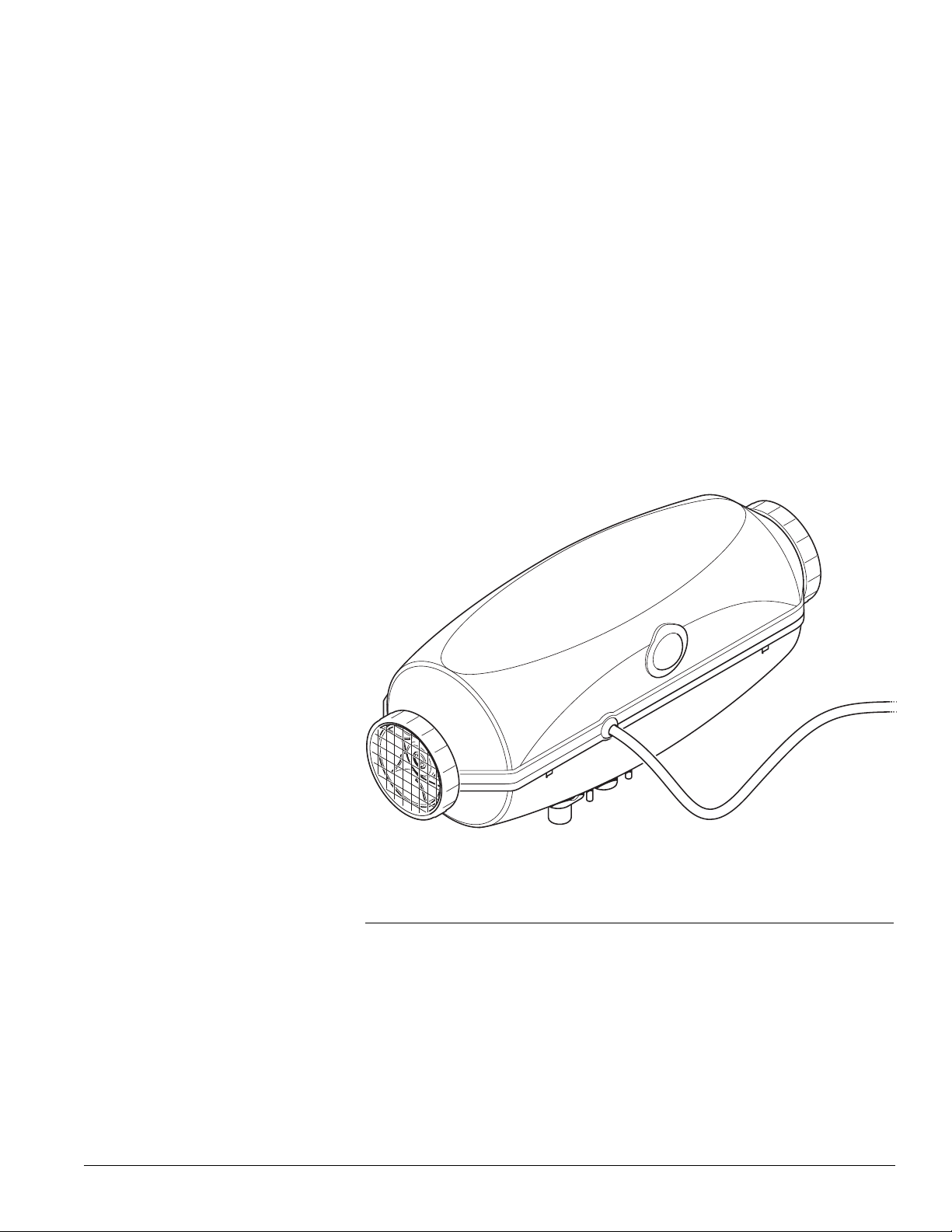
OVERVIEW
Proheat Air is a diesel-powered air heater that supplies heat for in-cab driver
comfort during cold weather. Available in either 2 or 4 kW models, the heater
consumes 95% less fuel than engine idling while supplying heat more quietly
and efficiently. Proheat Air includes a digital control panel for easy set-up and
control of the heater from inside the truck cab.
Easy to Use
The included Driver Control Panel (DCP) makes set-up and operation of the
heater quick and easy. The DCP features a large, backlit display that provides
at-a-glance display of heater status. Programmable start times mean drivers
can start the heater when away from the truck or automatically turn it on
when they are asleep.
PROHEAT AIR A2/A4 INSTALLATION MANUAL
Figure 1
This manual is provided to assist an Authorized Proheat Dealer in the installation
of a Proheat Air heater. Although trucks have been used in the examples,
applications are by no means limited to trucks.
B-1
Page 6
HEATED AIR
ELECTRICAL
CONNECTION
DUCTING
DRIVER CONTROL
PANEL (DCP)
HEATER
EXHAUST
FUEL PUMP
FUEL PICK-UP
AIR INTAKE
COMBUSTION
AIR INTAKE
Proheat Air heaters will help provide a comfortable cab or cargo temperature
without having to idle the vehicle’s main engine.
1. Cab or sleeper heat (engine off) – Proheat Air heaters will supply heat to
the cab or sleeper. Substantial savings through reduced fuel consumption
nd engine wear can be obtained by not idling the engine.
a
. Supplemental heat (engine running) – As the efficiency of modern diesel
2
engines have improved, there is less reject heat available to heat the
vehicle’s interior. Proheat Air heaters can be used while the vehicle is
operating to provide supplemental heat for the interior.
Proheat Air heaters are designed to be used in most classes of trucks, cabs of
heavy machinery, and cargo areas. Proheat Air heaters are not approved for
Marine applications.
Components and Basic Operation
An electric pump delivers diesel fuel to the Proheat Air heater
diesel fuel in a combustion chamber. An electric fan blows air over the heated
combustion chamber transferring heat to the air as it passes. The heated air
is then delivered through ducting to the area to be heated. Pre-combustion air
comes from an external air intake. Combustion exhaust is externally vented
from the vehicle. The Proheat Air heater is controlled by a Driver Control Panel
(DCP). The DCP is used to turn the heater on/off and it can be programmed
to start the heater at predetermined times.
The Proheat Air heater should be installed by an Authorized Proheat Dealer or
trained professional installer.
which burns the
B-2
Figure 2. Component Layout
PROHEAT AIR A2/A4 INSTALLATION MANUAL
Page 7
1.0
TECHNICAL
SPECIFICATIONS
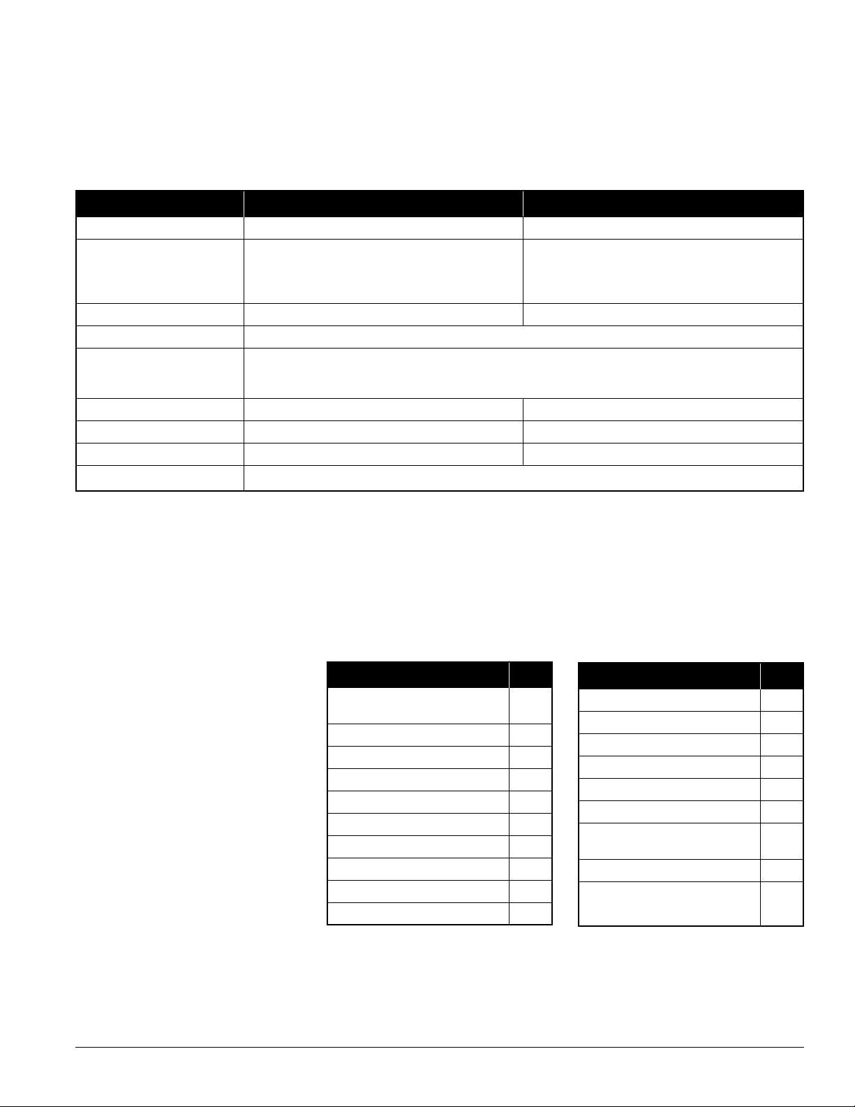
MODEL A2 (12V/24V) A4 (12V/24V)
RATING 2 kW (6,800 BTU) 4 kW (13,600 BTU)
OPERATING VOLTAGE
tand-By 0.4 W 0.4 W
S
Ignition 130 W 145 W
Maximum Heat 25 W 60 W
FUEL CONSUMPTION 0.03–0.06 US gal/hr (0.1–0.22 l/hr) 0.06–0.012 US gal/hr (0.21–0.46 l/hr)
FUEL TYPE ULSD, Diesel # 1, Diesel # 2, Arctic, B5 Bio-diesel
OPERATING Ventilation mode: -40°F to 149°F (-40°C to 65°C)
TEMPERATURE
RANGE
AIR FLOW 41 CFM (70 m³/hr) 65 CFM (110 m³/hr)
WEIGHT (Maximum) 7.7 lb (3.5 kg) 11.2 lb (5.1 kg)
DIMENSIONS (L x W x H) 14 x 4.75 x 6.14 inches (355 x 120 x 156 mm) 16.4 x 6.1 x 7.4 inches (417 x 154 x 189 mm)
WARRANTY Two years parts and labor
Heating Mode: -40°F to 104°F (-40°C to 40°C)
PACKAGE CONTENTS1.1
Check box carefully and report any missing parts to your dealer or supplier.
DESCRIPTION QTY
Air Heater A2 or A4
12 or 24 V 1
Heater to Battery Harness 2
Driver Control Panel (DCP) 1
DCP to Heater Harness 1
DCP to Ignition Harness 1
Fuses 7.5 or 15A 2
Fuel Pump 12 or 24 V 1
Fuel Pump to Heater Harness 1
Fuel Pump Bracket 1
Fuel Pickup Pipe 1
DESCRIPTION QTY
Fuel Lines Rubber 4
Fuel Lines Plastic 2
Fuel Line Clamps 8
Air Intake Silencer 1
Exhaust Pipe 1
Exhaust Pipe P Clamp 1
Installation Hardware
Package 1
Hot Air Duct (optional) 1
Owner's Manual 1
PROHEAT AIR A2/A4 INSTALLATION MANUAL
1-1
Page 8
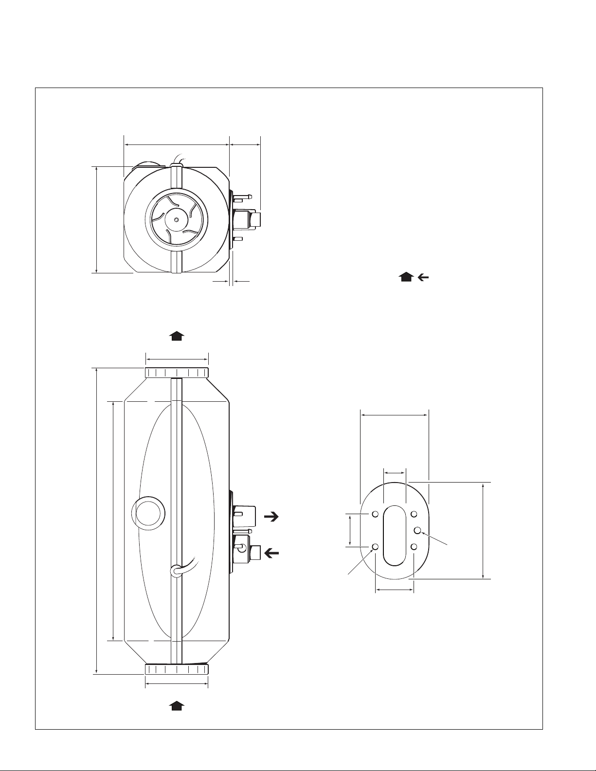
1.46"
(37 mm)
4.13" (105 mm)
1.73"
(44 mm)
1.88"
(74 mm)
4 x 0.26" DIA.
(7 mm DIA.)
1" (25 mm)
0.30" DIA.
(8 mm DIA.)
CABIN AIR
COMBUSTION AIR
14.0" (3 55 mm) 4.9" (124 mm)
3.0" (75 mm)
3.0" (75 mm)
.157"
(4 mm)
4.75"
(120 mm)
1.42"
(36 mm)
10.8" (275 mm)
PHYSICAL A21.2
1-2
PROHEAT AIR A2/A4 INSTALLATION MANUAL
Page 9
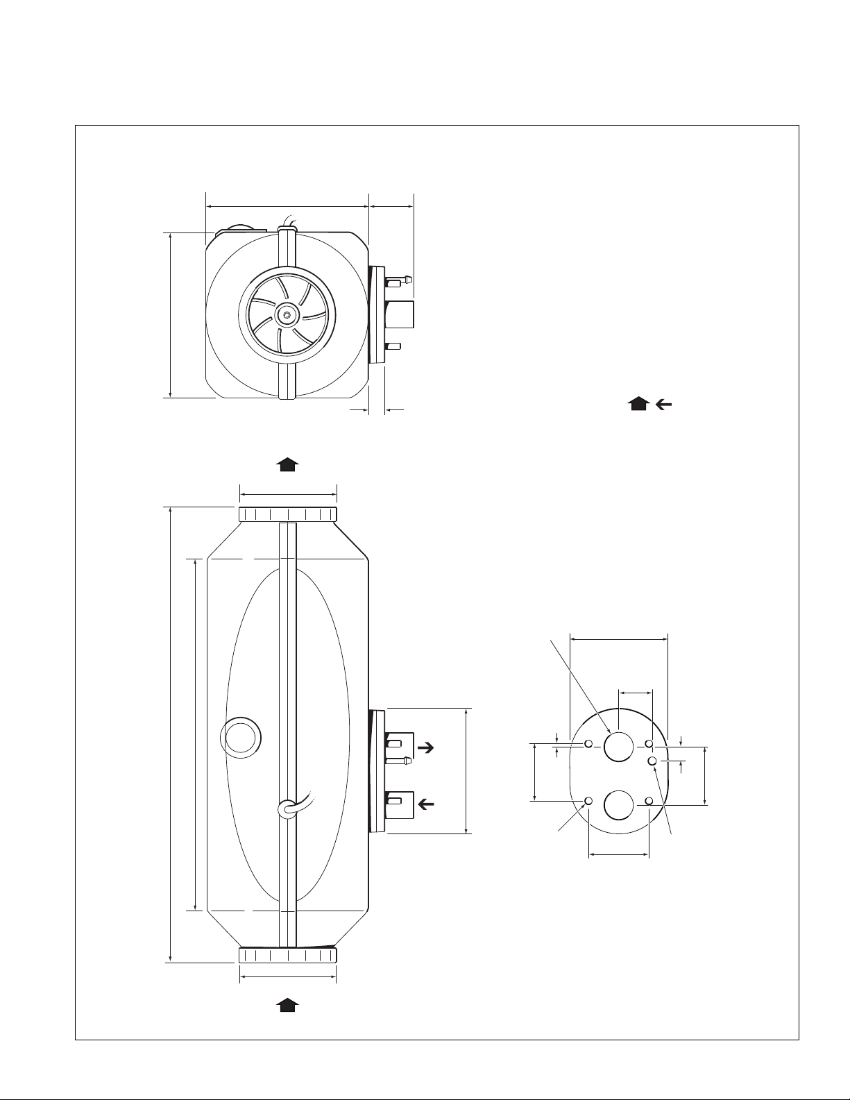
PHYSICAL A41.3
2.13"
(54 mm)
2.09"
(53 mm)
0.51" (13 mm)
0.12" (3 mm)
2.95"
(116 mm)
1.22"
(31 mm)
2.31"
(91 mm)
2.20"
(56 mm)
4 x 0.26" DIA.
(7 mm DIA.)
0.30" DIA.
(8 mm DIA.)
2 x 1.06" DI A.
(27 mm DI A.)
CABIN AIR
COMBUSTION AIR
5.87"
(149 mm)
1.57"
(40 mm)
16.4" (417 mm) 5.95" (151 mm)
3.54" (90 mm)
3.54" (90 mm)
12.6" (320 mm)
.55" (14 mm)
PROHEAT AIR A2/A4 INSTALLATION MANUAL
1-3
Page 10

1-4
PROHEAT AIR A2/A4 INSTALLATION MANUAL
Page 11

2.0
INSTALLATION
2.1
2.2
TOOLS & PARTS REQUIRED
• Protective wire loom where required
• Grommets
• Cable ties
• Electrical tape
• P clamps (metal or plastic)
• Multimeter
• Hacksaw
• Drill
• 1" (25 mm) Unibit or Step Bit
• 1" (25 mm), 3" (75 mm), or 3.5" (90 mm) hole saw
• Reciprocating saw
• Metric Wrenches 7mm, 8mm, 12mm, 17mm
• Metric Allen Keys 3mm
• Mounting templates (located at back of manual)
• Hot Air Duct
• Hot Air Vents
GENERAL CONSIDERATIONS
2.2.1
2.2.2
NOTICE
Other considerations will present
themselves depending on different
applications. For answers to questions
specific to your applications, please
contact your dealer or Proheat
technical assistance.
PROHEAT AIR A2/A4 INSTALLATION MANUAL
Environmental
•Proheat Air heaters are designed for mounting inside a vehicle or cargo area only.
• Although Proheat Air heaters are designed to operate over a very wide range
of environmental conditions, extreme temperature, humidity and altitude may
affect optimum performance.
Access for regular servicing
•Ensure the mounting location provides sufficient access for regular servicing
including access to the glow plug, cable harnesses, fuse and housing.
• It may be necessary to alter or relocate vehicle hardware that may interfere
with the heater installation or ease of service. Always check with the vehicle
owner before making any modifications.
• Fuel, power and air ducts should be located and secured in a manner that
allows easy removal of the heater or access to replacement parts.
• SeaStar Solutions is not responsible for additional time taken during warranty
or repair arising from awkward or difficult mounting locations. The Owner is
responsible for any extra time incurred due to access issues.
2-1
Page 12
2.2.3
SERIAL NUMBER LOCATION
Fuel
efer to figure 17 for information on fuel line lengths and maximum lift of
•
R
fuel pump.
• Use the supplied fuel pick-up pipe, do not tap into the vehicle’s fuel lines.
• Fuel lines must not be run through the vehicle cab, ensure all lines are well
secured and protected from sharp edges and chaffing and are .
CAUTION
2.3
Combustion air must be drawn from outside the vehicle only, risk of
suffocation may occur otherwise.
Exhaust must be vented directly outside the vehicle and clear of the cab
outline. Always use the supplied exhaust pipe to ensure harmful exhaust
gases are vented clear of the vehicle.
Maintain a tight seal between the heater and the vehicle floor to prevent
ingress of exhaust gases into the vehicle.
LOCATING THE HEATER
The most suitable location for mounting the heater will vary depending on the
type of vehicle.
Recommended locations are under the bunk in sleeper applications or
behind/under the passenger seat in day-cab applications.
Using the supplied A2 or A4 mounting template as a guide, choose a location that:
• won’t interfere with normal operation and storage of gear
• allows easy access for regular servicing
• has a smooth, level surface and mounts the heater within 5 degrees of level
NOTICE
Prior to installation, record the heater
model and serial number on the
warranty card. You will need to send
this in for warranty registration
Note: If the floor surface is uneven, use an optional mounting plate to
ensure there is a tight seal between the heater and the vehicle floor.
• is within allowable distance of the battery compartment and fuel tanks
(refer to 2.8.2 and 2.9.1)
• is free of any obstruction under the cab such as brake or air lines, electrical
wiring, cross members or anything else that may interfere with the installation
and connection of fuel lines, exhaust pipe and air intake silencer
• meets the requirements for location of ducts and air vents, refer to figure 4,
23 and 24 for information on air duct options
Figure 3. Serial Number Location
2-2
PROHEAT AIR A2/A4 INSTALLATION MANUAL
Page 13
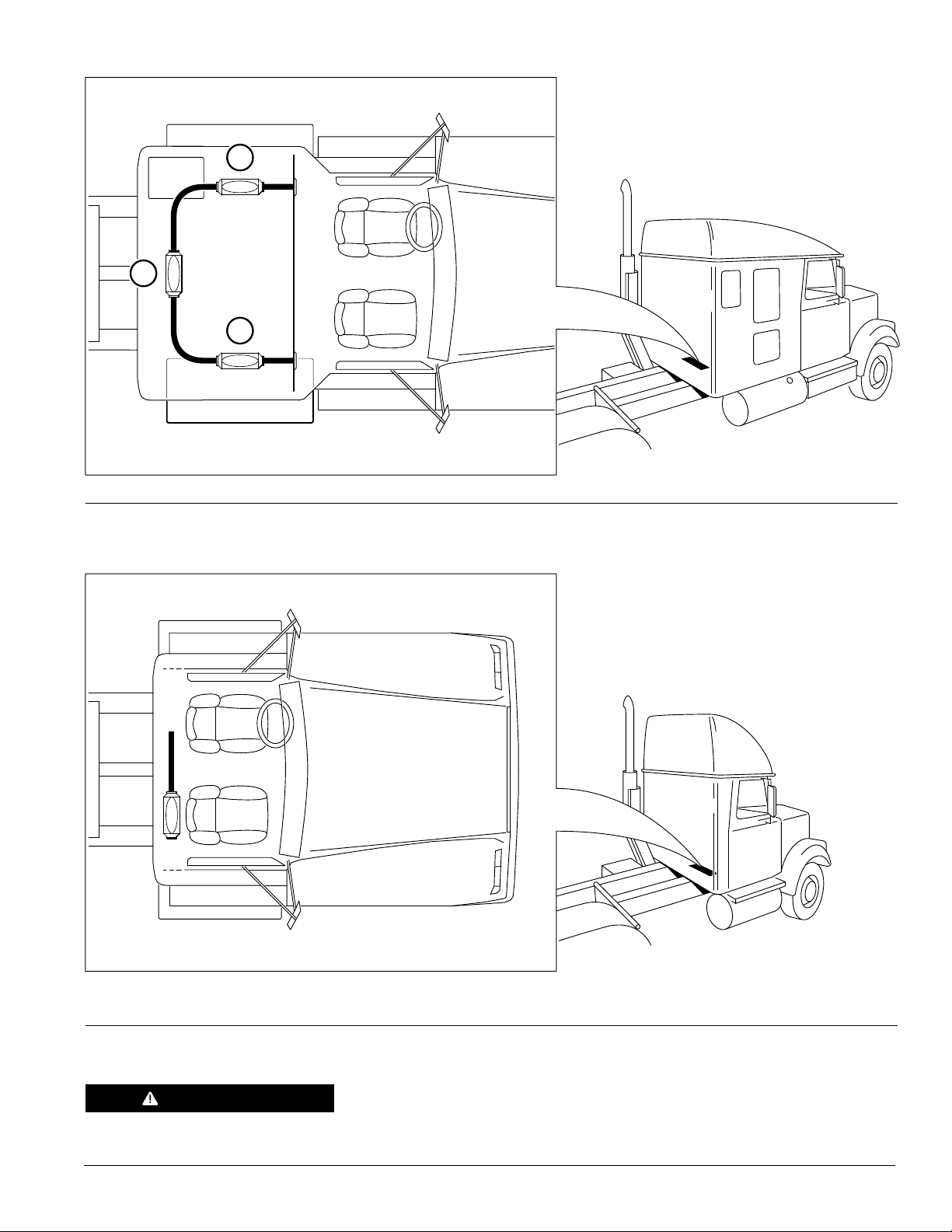
Figure 4. Recommended Mounting Locations for a Sleeper Cab.
1
3
2
Figure 5. Recommended Mounting Locations for a Day Cab.
CAUTION
PROHEAT AIR A2/A4 INSTALLATION MANUAL
Protect the heater from outside damage (DO NOT cover or lean anything
over the heater).
2-3
Page 14
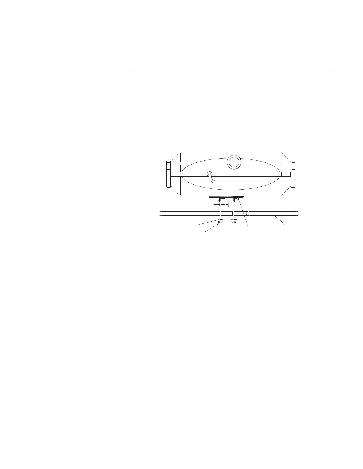
2.4
NUT (4)
SILICON GASKET
FLANGE
SPRING WASHER (4)
CAB FLOOR
INSTALLING THE HEATER
2.4.1
Direct Mount
1. Move or remove any hardware to gain access to mounting location.
. Using the appropriate mounting template (supplied at rear of installation
2
manual) mark the location of the mounting, exhaust, air intake and fuel holes.
3. Using a drill bit and hole saw, drill 6 holes in the floor paying particular
attention to the underside of the vehicle.
4. File down any sharp edges and test fit the heater. Trim any excess as
required to ensure the heater fits without binding and the heater gasket
sits flat on the floor to create a tight seal.
5. Install the heater and secure with the supplied hardware (refer to figure 6).
2.4.2
Figure 6. Heater Mounted Directly to Cab Floor.
Optional Mounting Plate
This option is recommended for applications where direct mounting of the
heater is not possible such as:
• Uneven floors
• Composite or other heat sensitive
flooring material
1. Move or remove any hardware to gain access to mounting location.
2. Using the mounting plate as a guide, mark the location of the areas to
be drilled.
3. Using a 3” hole saw for A2 or a 3.5” hole saw for A4, cut a hole in the
floor paying particular attention to the underside of the vehicle to ensure
you are not cutting through anything but the floor.
4.
Drill four holes for the plate mounting hardware if not using self tapping screws.
5. Secure the heater to the mounting plate using the supplied hardware
(refer to figure 7).
6. File down any sharp edges and test fit the heater. Trim any excess
material as required to ensure the heater fits without binding and the
mounting plate gasket creates a tight seal.
7. Apply sealant to any exposed metal edges to prevent corrosion.
8. Fasten the mounting plate to the floor using #12 self tapping screws x
1.5" (40 mm) (minimum) or 1/4" (6 mm) machine screw and nut.
• Extra thick flooring material
• Additional insulation under
the vehicle
2-4
PROHEAT AIR A2/A4 INSTALLATION MANUAL
Page 15

DIRECTION OF
VEHICLE TRAVEL
NUT (4)
SILICON GASKET FLANGE
HEX. HEAD #12
SELF TAPPING
SCREW x 1.5" (4)
SPRING WASHER (4) CAB FLOOR
FOAM
GASKET
OPTIONAL
MOUNTING
PLATE
Figure 7. Optional Mounting Plate.
CLAMP
CLAMP
DIRECTION
OF VEHICLE
TRAVEL
HOSE
2.5
CAUTION
Combustion air intake must draw
air from the outside of the vehicle
to prevent risk of suffocation.
Maintain adequate distance between
combustion air intake and exhaust
outlet to prevent exhaust gases
from entering the heater.
COMBUSTION AIR INTAKE
SILENCER
The air intake silencer acts as an air flow stabilizer for the heater. Operation
of the heater without the silencer is not recommended.
1. Using the supplied 16-25 hose clip, attach the air intake to the heater
combustion air intake and secure.
2. Route the silencer in the opposite direction of the vehicle motion pointing
down slightly (refer to figure 9).
A4 heaters only: Secure the air intake silencer to the underside of the vehicle.
3. For extra thick floors or additional insulation (A2 heaters only), cut a 2"
(50 mm) length of 5/8" (15mm) inside diameter heater hose and attach
to the heater combustion air intake with a hose clamp (refer to figure 8).
4. Insert the air intake silencer to the free end of the heater hose and
secure with a hose clamp ensuring the silencer points in the opposite
direction of vehicle travel and pointing down slightly (refer to figure 9).
PROHEAT AIR A2/A4 INSTALLATION MANUAL
Figure 9. Air Intake Silencer.Figure 8. Air Intake Silencer Extension.
2-5
Page 16

2.6
EXHAUST PIPE INSTALLATION
The exhaust pipe directs combustion exhaust gas away from the heater.
The exhaust pipe tip must be clear of the underside of the vehicle to prevent
combustion gas from re-entering the cab.
2.6.1
2.6.2
General Considerations
Point exhaust toward rear of vehicle and angle tip down slightly to prevent
build up of snow or mud (refer to figure 10).
Maintain a slight downward angle away from heater, if this is not possible,
drill 1/8” holes at the lowest points to allow moisture from combustion to
drain out (refer to figure 11).
Ensure exhaust pipe tip is clear of rear or side of cab to prevent buildup of
gases beneath vehicle.
DO NOT allow exhaust pipe to touch painted or other heat sensitive material
such as hoses or wiring.
Secure exhaust pipe with P clamps to prevent vibration and rattles.
Installation
Test fit the exhaust pipe and select the shortest route to clear the rear of
the vehicle.
If necessary, shorten exhaust pipe at the heater end by cutting with a hack
saw, do not use shears or snips as they will distort the exhaust pipe and may
cause leaks.
Locate position of P clamps and mark for drilling if required.
WARNING
Exhaust gases must not enter the
vehicle interior. Direct exhaust
pipe away from vehicle.
Secure the exhaust pipe to the heater using the supplied clamp and tighten
the P clamp(s).
Figure 10. Exhaust Pipe Direction.
2-6
PROHEAT AIR A2/A4 INSTALLATION MANUAL
Page 17

DRILL A 0.11" (3 mm) HOLE TO DRAIN MOISTURE
VELCRO
®
ADHESIVE STRIPS
IGNITION KEY
CONNECTION
HEATER CONNECTION
EXTERNAL TEMPERATURE
SENSOR (T3) CONNECTION
DRIVER CONTROL
PANEL (DCP)
IF EXHAUST PIPE IS AT A 90° OR GREATER ANGLE
Figure 11. Exhaust Pipe Drainage.
2.7
2.7.1
DCP INSTALLATION
The Driver Control Panel (DCP) is used to turn the heater on and off, set heater
temperature and can be programmed to start the heater at predetermined
times. The DCP provides a wealth of information including current temperature,
heater power level, current time and diagnostic codes.
Location
See section 2.8 on wiring for information regarding connecting the DCP to the
heater and the vehicle’s ignition.
Choose a location that is within the desired heating area and is easily
accessible by the user.
For sleeper cabs, install in the sleeper, close to the driver’s head for easy
access and heat regulation.
For day cabs, install on or near the dash within easy reach of the driver.
The driver control panel is designed for surface mounting and does not
require the drilling of any holes however, a small hole is required if hidden
wiring is desired.
Check behind the mounting location panel to ensure there is adequate room
for the connectors and wire harness.
Figure 12. Driver Control Panel (DCP).
PROHEAT AIR A2/A4 INSTALLATION MANUAL
Drill a 3/4" (19 mm) hole in the panel to push the DCP connectors through.
Using the template in section 6.5 mount the DCP to the panel using the
supplied Velcro®Adhesive strips.
2-7
Page 18

2.8 WIRING & ELECTRICAL
CONNECTIONS
he Proheat Air heater is available in 12 or 24 volt DC models and work with
T
negative ground electrical systems only.
2.8.1
WARNING
DO NOT use on a positive ground
vehicle.
CAUTION
If repair to the vehicle requires
welding, disconnect the heater
power at the heater.
2.8.2
General Considerations
• All wire harnesses come complete with connectors and should not require
alteration.
• If making new connections, they must be crimped and soldered using rosin
core, not acid core solder.
• Ensure the vehicle batteries are in good condition and that connections are
clean and tight.
• Do not kink or abrade wires when routing.
• Use wire loom to protect cables when required.
• Use grommets whenever passing cable through a metal surface.
• Ensure wires are well secured and supported.
• Wires should be secured within 4" of all connections.
• All wires must have sufficient slack to prevent strain during vehicle operation.
Electrical Connections
• Main power to heater
• Power and signal from heater to Driver Control Panel (DCP)
- Pin 1 Yellow wire Key + DCP Backlight continuous on
- Pin 2 Green wire Key + Run Mode. When key on heater is in continuous
run. Key off heater is in Pre-Programmed Run Time (default 30 min)
- Or Permanent Override to Continuous Run Heat Mode
- Pin 2 Green wire to a continuous battery positive source. Heater will run
until manually turned off.
• Switched power to Driver Control Panel
• Power from heater to fuel pump
• External temperature Sensor (optional)
2-8
HARNESS LENGTH
Main Power Heater to Battery and Fuse Holder 15 feet
Heater to Fuel Pump 19.7 feet
Heater to Driver Control Panel 15 feet
Driver Control Panel to Ignition 15 feet
PROHEAT AIR A2/A4 INSTALLATION MANUAL
Page 19

2.8.3
+
–
EXTERNAL
TEMPERATURE
SENSOR (T3)
OPTIONAL
DO NOT
USE
TO IGNITION
SWITCHED VOLTAGE
DRIVER CONTROL
PANEL (DCP)
CONNECTOR
CONNECTOR
CONNECTOR
CONNECTOR
PINK
BLUE/
WHITE
SEE NOTE ON PAGE 2-8
F
OR WIRING OPTIONS
WHITE
BROWN
BLUE
BLACK
WHITE
BROWN
BLUE
BLACK
BLUE
BLACK
BLUE/WHITE
GREY
YELLOW
GREEN
WHITE
BROWN
RED
BLACK
RED
BLACK
RED
BLACK
CONNECTOR
HEATER
GREEN
YELLOW
GREEN
YELLOW
CONNECTOR – MALE PIN
CONNECTOR – FEMALE PIN
CONNECTOR
FUSE
FUSE
FUEL PUMP
BATTERY
Wiring Schematic
Figure 13. Wiring Schematic.
PROHEAT AIR A2/A4 INSTALLATION MANUAL
2-9
Page 20

FUSE HOLDER HARNESS
POWER SUPPY HARNESS
FUSE
RED (+)
POSITIVE
BLACK (-) NEGATIVE
2.8.4
NOTICE
Ensure the battery terminals are
clean and free of corrosion.
Main Power to Heater
The main power harness consists of two cables each with its own fuse to protect
both the heater and the wire harness from damage due to short circuits.
• Remove fuses from fuse holders
Connect fuse holder harness to battery terminals observing correct polarity
•
and battery terminal
• Connect fuse holder harness to main power harness
• Route main power harness from the battery box to the heater and connect
• Bundle and secure excess wire out of the way
• Protect any exposed wire harness with wire loom
• Do not install fuses until the heater is completely installed and all
connections are tested
2.8.5
Power and Signal from Heater to Driver Control Panel
Power is supplied from the heater to the Driver Control Panel (DCP). Control
signals such as heater start or temperature settings are sent to the heater.
Information such as current temperature, heater status and diagnostic
information is sent from the heater to the DCP for display.
Connect the round connector from the DCP to the cable harness. Starting at
the DCP mounting location, feed the wire back through to the heater and
connect to the heater main harness.
2-10
Figure 14. 12V DC Connections.
PROHEAT AIR A2/A4 INSTALLATION MANUAL
Page 21

FUSE
RED (+)
POSITIVE
BLACK (-) NEGATIVE
FUSE HOLDER HARNESS
POWER SUPPY HARNESS
2.8.6
Switched Power to Driver Control Panel
The Driver Control Panel can determine if the vehicle is running or not by
monitoring the switched power coming from the ignition. By connecting this
cable, longer run times for supplemental heat is possible.
Connect the two pin connector to the DCP and feed the wire to an ignition
witched source. Connect both the Green and Yellow wires to a source that
s
goes HIGH when the ignition is ON.
2.8.7
NOTICE
It is possible to use one wire loom
for both fuel line and wiring harness.
Fuel Pump
The fuel pump is highly regulated and receives power and signal from the
controller located inside the heater.
Starting at the fuel pump, connect the Yellow/Green harness to the fuel
pump connector.
Route the wiring harness back to the heater and connect to the
corresponding connector at the heater main harness.
Bundle extra wire and secure out of the way with cable ties - DO NOT cut or
shorten the wire unless necessary.
PROHEAT AIR A2/A4 INSTALLATION MANUAL
Figure 15. 24V DC Connections.
2-11
Page 22

2.8.8 Optional External Temperature Sensor
CABLE TIE MOUNT
EXTERNAL
TEMPERATURE
SENSOR
MUST BE FREE AND CLEAR OF
ANY OBSTRUCTION INCLUDING
MOUNTING SURFACE
The external temperature sensor plugs in to a connector on the Driver Control
Panel (DCP) and temperature information from this sensor can be used for
information or for controlling heater output.
An external temperature sensor is used when the DCP is not in the same
rea as the heater such as in a cargo area. An external temperature sensor
a
can also be used to monitor outside air temperature for information only. In
this case it cannot be used to control heater output.
The temperature sensor must be mounted:
• About midpoint between the floor and ceiling
• Within the length of the cable to the DCP - do not extend the cable
• Away from the hot air stream from the heater or the vehicle OEM heater system
• Away from direct sunlight or windows
• In front of any curtains or dividers
When installing the temperature sensor choose a location noting the general
considerations above.
Affix to a solid surface using a cable tie mount or adhesive tape (refer to
figure 16).
Route wire back to DCP and connect.
Program DCP per instructions on page 3-1 and 6-1.
2-12
Figure 16. External Temperature Sensor.
PROHEAT AIR A2/A4 INSTALLATION MANUAL
Page 23

2.9
90°
45°
A
A MAX. HEIGHT ABOVE FUEL PICK-UP = 39.25" (1000 mm)
B MAX. RISE = 78.50" (2000 mm)
1 MAX. LENGTH INC. JOINTING PIECE = 27.5" (700 mm)
2 MAX. LENGTH INC. JOINTING PIECE = 236.25" (6000 mm)
3 MAX. FUEL PUMP ANGLE = 90°
MIN. FUEL PUMP ANGLE = 45°
B
1
3
2
FUEL SYSTEM
he Proheat Air heater comes complete with all fuel system components
T
required to supply the heater with diesel fuel. Do not substitute any hardware
or tap in to the OEM fuel lines.
2.9.1
CAUTION
DO NOT kink or pinch fuel line when
routing lines.
General Considerations
• Cut fuel line with a sharp knife on a solid surface and ensure all cuts are
square with no burrs or pinching (refer to figure 18).
• Mount the fuel pump in a vertical position and within 27.5” (700 mm) of
the fuel pickup using the supplied mounting hardware (refer to figure 17).
• Route fuel lines away from any abrasive corners and hot or moving parts
and ensure they are well secured.
• Protect any exposed fuel line and fuel pump wires with wire loom.
Figure 17. Fuel System.
PROHEAT AIR A2/A4 INSTALLATION MANUAL
2-13
Page 24

2.9.2
DRILL 5/8" (16 mm) HOLE
NUT
WASHER
PICK-UP
GASKET
Fuel Line Installation
• The hose must be cut even, without burrs or deformation. The ends must be
pushed close to each other inside the connection hose to prevent air bubbles.
• The fuel line from the pump to the heater must incline directly to heater
(refer to figure 22).
Figure 18. Hose Connections.
2.9.3
CAUTION
DO NOT connect to the vehicle
return line.
CAUTION
To prevent fuel system contamination
DO NOT allow drill chips to fall into
the fuel tank when drilling the hole.
WARNING
Drilling the fuel tank may not be
acceptable in some jurisdictions.
DO NOT drill the fuel tank on
passenger carrying vehicles such
as school buses.
Fuel Pick-Up Tube Installation
• Identify a location for the hole in the tank where the fuel pick-up is
protected (center of tank is recommended).
• Fuel pick-up to be installed in a hole drilled into the fuel tank with a step
drill (refer to figure 19).
• Determine the depth of the fuel tank at the desired fuel pickup location.
• Cut pick-up tube 3" (76 mm) to 4" (101 mm) from bottom of tank
• Bottom of pick-up must be cut at a 45° angle.
• Tighten stand pipe until secure
2-14
Figure 19. Fuel Pick-Up
PROHEAT AIR A2/A4 INSTALLATION MANUAL
Page 25

45˚±15˚
LARGER #11 HOSE CLAMP
LARGER #11 HOSE CLAMP
CUT BOTTOM
OF FUEL PICK-UP
AT AN ANGLE
Figure 20. Fuel Pick-up Depth
3" (76 mm) TO 4" (101 mm) CLEAR OF BOTTOM OF TANK
PROHEAT AIR A2/A4 INSTALLATION MANUAL
Figure 21. Hose Clamps.
2-15
Page 26

2.9.4
P
U
M
P
#
9
#
1
1
#
9
#
9
R
U
B
B
E
R
H
O
S
E
C
O
N
N
E
C
T
O
R
S
E
L
A
S
T
I
C
B
E
A
R
I
N
G
E
L
E
C
T
R
I
C
A
L
C
O
N
N
E
C
T
O
R
F
U
E
L
P
U
M
P
C
L
A
M
P
B
O
L
T
M
6
X
3
0
-
5
,
6
-
A
3
P
R
U
B
B
E
R
H
O
S
E
C
O
N
N
E
C
T
O
R
S
F
L
O
W
90°
45°
MAX. FUEL PUMP ANGLE = 90°
MIN. FUEL PUMP ANGLE = 45°
F
L
O
W
Fuel Pump Installation Procedure
1. Install the fuel pump in a location away from interference such as
rubbing against vehicle frame or cab.
2. Locate the area to install the pump. A bracket may be fabricated is a
suitable horizontal surface cannot be found.
3. Observe the fuel flow arrow on the pump label - arrow should point in
the direction of the heater.
4. Place the elastic bearing over the pump.
5. Connect the fuel pump bracket over the elastic bearing, using the
required bolt and nut. Tighten the clamp onto the pump.
6. Using # 11 clamps, connect both rubber hose connectors to the fittings
(refer to figure 21).
7. Using # 9 clamps, connect the fuel lines from the tank and the heater
to the fuel pump.
8. Attach the pump to the vehicle or bracket.
9. Route wire harness from heater to the pump.
10. Connect to the pump and secure the wires.
11. The pump must be installed ± 45 degrees of vertical to prevent air
bubbles from forming (refer to figure 22).
Figure 22. Fuel Pump Angle.
2-16
Figure 23. Fuel Pump.
PROHEAT AIR A2/A4 INSTALLATION MANUAL
Page 27

2.10 AIR DUCT INSTALLATION
MINIMUM
DIAMETER
3" (75 mm)
MAXIMUM LENGTH
394" (10 m)
INLET
OUTLET
INLET
OUTLET
2.10.1
General Considerations
• Use ducts and vents temperature rated for 300°F (150°C) with minimum
nside diameter of 2.95 inches (75 mm).
i
• DO NOT tap in to the vehicles OEM system.
• Avoid directing hot air from heater outlet vent within 12” (30 cm) or directly
at non temperature rated materials or people.
• Use the table below to determine maximum length of duct and maximum
number of bends.
• Use the fewest number of bends possible while ensuring there are no
airflow restrictions such as tight bends or kinks.
• Position inlet and outlet air ducts away from any obstructions and as far
apart as possible to prevent air short cycling (refer to figure 25).
Heater Duct Inside Total Duct Each 90° Maximum
Diameter Length Bend Bends
A2 2kW 3.0" (75 mm) 30 feet (9 m) 3 feet (1 m) 5
A4 4kW 3.0" (75 mm) 21 feet (6.4 m) 3 feet (1 m) 5
A4 4kW 3.5" (90mm) 30 feet (9 m) 3 feet (1 m) 5
Figure 24. Ducting.
PROHEAT AIR A2/A4 INSTALLATION MANUAL
Figure 25. Air Short Circuit.
2-17
Page 28

1
2
2.10.2
Installation
1. Select the area where the air vents will be situated - see general
considerations.
2. Using a hole saw, cut a 3" (75 mm) hole for the outlet air duct (for
sleeper application only, not needed in day cab application).
3. Cut a second hole for the air inlet duct if required.
4. Using a hose clamp, secure the duct to the air vent and install air vent.
5. Trim duct length as required ensuring there is no restriction to air flow.
6.
Attach duct to air heater outlet and inlet collars (if used) using hose clamps.
7. Support and secure the duct.
1 INLET LOCATION
2 OUTLET LOCATION
Figure 26. Air Duct Installation.
2-18
PROHEAT AIR A2/A4 INSTALLATION MANUAL
Page 29

FIRST TIME START UP3.0
26
35
4
1
1 Status LED Light
2 Fan Button – Fan On or Off
3 Left Button
4 Timer/Enter Button
5 Right Button
6 Heat Button – Heat On or Off
3.0.1
3.0.2
3.1
3.1.1
Inspect the entire installation for:
a. Loose bolts.
b. Loose hose and hose clamps.
c. Loose wire and wire connections.
d. Kinked hoses or wiring.
e. Battery connection for correct polarity.
Verify the battery power
Install both fuses at the battery box and the heater. Use 15A fuses for 12
volt systems and 7.5A fuses for 24 volt systems.
SETTING UP THE DCP
Set Time
The time symbol (00:00) appears in the lower left corner of the display, the
first two 00: flash. Using the LEFT and RIGHT buttons, set the hour. Press
the TIMER button. Set the minutes. Press the TIMER button.
PROHEAT AIR A2/A4 INSTALLATION MANUAL
Figure 27 Driver Control Panel (DCP).
3-1
Page 30

3.1.2
Set Day
After setting the time, the day will appear in the upper left corner of the display.
Using the LEFT and RIGHT buttons, set day. Pressing TIMER to set.
NOTICE
3.1.3
3.1.4
3.1.5
Confirm
fter setting the day of the week, a RED light starts to flash on top center of
A
the DCP. E: 00 will appear in the center of the display. Press TIMER to clear.
The light will stop flashing and the temperature, time and day will appear in
the display.
Selecting Temperature Sensor
Press and hold the TIMER button for 3 seconds. Using the RIGHT button, go
to Menu 4 (ME4) and press TIMER to select. Select the temperature sensor
using the RIGHT button and pressing TIMER. For initial start up, select T-2.
T-1 is located inside the heater and will measure air entering the heater. T-1
will show on the display.
T-2 is located inside the DCP and will show the ambient temperature in the cab.
T-2 will show on the display.
T-3 is an optional external temperature
and can be located anywhere inside or outside.
sensor that is connected to the DCP
Set Heating Mode: Menu 5
Using the RIGHT button, scroll to ME5 and press TIMER to select. Using the
RIGHT button, select P and press TIMER.
3.1.6
3.1.7
Prime the Fuel System: Menu 9
Before starting the heater, it is necessary to prime the system to purge air
from the fuel lines and ensure proper function. Priming is a timed feature and
can be set to 100s, 180s, 360s, or 500s depending on the distance
between the heater and the fuel tank.
Note: To prevent over fueling during priming, disconnect fuel line at heater and
direct fuel in to a suitable container. Once priming is complete, reattach fuel
line to heater ensuring no air enters the fuel line.
Using the RIGHT button, scroll to ME9 and press TIMER to select.
A password is set to prevent accidental activation of the feature. The
password 123 can be entered one digit at a time by scrolling up or down and
pressing the TIMER button to advance to the next digit.
Set the primer run time of the fuel pump using the LEFT or RIGHT button and
pressing TIMER.
180 seconds is recommended for the initial start up.
The priming function can be stopped at any time by pressing the FAN button.
Check Fuel Line
When the fuel line is full, the heater is ready to start.
3-2
PROHEAT AIR A2/A4 INSTALLATION MANUAL
Page 31

3.1.8
Checking the system’s function
Ventilation:
Press the FAN button and check function
• Check for running fan noise.
• Increase and decrease the FAN RPM using the Left and Right buttons
and check the air flow.
• Check for restriction on the inlet and outlet air vents.
• Turn the FAN OFF by pressing the FAN button.
Heating:
Press the HEAT button and check the heater function
• Ensure the heater cycles through the entire heating sequence (refer to
section 4.0).
• Check for proper air flow to the combustion inlet and exhaust outlet.
• Using the increase and decrease buttons, check the heaters power.
• Measure for difference of temperature between the inlet and outlet vents.
• Turn the heater OFF by pressing the HEAT button.
3.1.9
Pre-Check
Fan
Glow Plug
Fuel Pump
Elapsed
Time
Figure 28. Sequence of Operation.
On
Off
Off
1 - 3 sec.
Pre-Heat
30 sec.
Off
On
Off
Set the heater for the customer applications such as:
• Temperature sensor selecting
• Heating Mode
Shut
Down
Sequence
360 sec.
START UP SEQUENCE
Fuel &
Fan
On
On
On
Ignition
90 sec.
On
On
On
2nd
Attempt
Pre-Heat
Off
On
Off
30 sec.
2nd
Attempt
Fuel & Fan
On
On
On
If Required
90 sec.
2nd
Attempt
Ignition
On
On
On
Normal
Operation
On
Off
On
DCP
Controlled
On
Off
Off
PROHEAT AIR A2/A4 INSTALLATION MANUAL
3-3
Page 32

3-4
PROHEAT AIR A2/A4 INSTALLATION MANUAL
Page 33

4.0
NORMAL OPERATING
SEQUENCE
4.0.1
4.0.2
4.0.3
NOTICE
In Precheck and Ignition modes the heat
symbol will be flashing on the DCP.
4.0.4
NOTICE
To increase the heating demands, use
the left (decrease) and right (increase)
buttons.
Switch "ON"
After powering up the heater, prime the fuel pump and set the DCP
(Temperature Sensor and Heating Mode) the heater is ready to start. Pushing
the HEAT button, the heater goes to "Precheck".
Precheck
The motor runs for 10 seconds and the DCP performs a short diagnostic
cycle, checking components for proper ranges, short circuit and open circuits.
If there are no errors the heater goes to “ignition”.
Ignition
Ignition is indicated by the flashing heat symbol on the display of the DCP.
The heater starts to glow for 30 seconds. The fuel pump starts, and the glow
plug illuminates. 2 seconds after the glowing time, the motor starts in full
speed. Once the flame sensor reaches the required temperature, the heater
switches off the glow plug and enters into “full output”. If the start is not
successful the heater will attempt to restart one more time.
Full Output
The heat symbol stops flashing and the heater enters the demanded heating
mode. Once the temperature sensor reaches 120°C (248°F) at the heater,
the heater shuts the fuel pump off and goes to “Purge”.
4.0.5
4.0.6
NOTICE
After 6 minutes cool down, turn OFF
the heater and reset the menu number
5 (ME 5), for customer applications.
PROHEAT AIR A2/A4 INSTALLATION MANUAL
Purge
Purge is indicated by a flashing FAN symbol on the display of the DCP. The fuel
pump shuts off immediately. The blower motor continues to run for 6 minutes
to cool down the combustion chamber. After 6 minutes the DCP checks the
air temperature at the heater. If the temperature is above 140°F (60°C), the
blower will run for 6 more minutes. When the temperature is below 140°F
(60°C) the motor will shut OFF. The heater will now enter Standby.
Standby
The heater continues checking the ambient temperature using the preselected temperature sensor. Once the temperature drops below the preset
temperature, the heater will re-enter “Precheck” and repeat steps 2 to 6. The
heater will continue to repeat these steps until it is switched “OFF.”
Inspect the installation again for leaks.
TO ENSURE FULL WARRANTY COVERAGE COMPLETE THE WARRANTY CARD
AND MAIL TO SEASTAR SOLUTIONS.
4-1
Page 34

4-2
PROHEAT AIR A2/A4 INSTALLATION MANUAL
Page 35

PROHEAT WARRANTY5.0
Non-standard installations, that is, those requiring a departure from published installation
instructions, should not be undertaken without first having consulted SeaStar Solutions.
Coverage for warrantable parts, at the discretion of SeaStar Solutions will be made to
the claimant in the form of repair, replacement or credit. Warranty labor payments will
be made only to Authorized Proheat Dealers in accordance with the Standard Repair
Times (SRT's) as published by SeaStar Solutions. Articles which are returned as defective,
but which are found to meet the specifications agreed upon, shall be subject to a
retesting charge.
The warranties set forth herein are the sole warranties made by SeaStar Solutions
in regard to the Proheat heater system. SeaStar Solutions makes no other warranties,
expressed
SeaStar Solutions warrants the Proheat Heater to be free of defects in material and
workmanship under design usage and service conditions for two (2) years on parts
and labor from the date of first installation. Replacement parts are covered for the
remainder of the heater's warranty or ninety (90) days, which ever is greater. This
warranty does not apply to damage or failure of the Proheat Heater or the vehicle into
which it was installed due to improper installation, assembly, maintenance, abuse,
neglect, accident, or the use of parts not supplied by SeaStar Solutions. Accessories
supplied, but not manufactured by SeaStar Solutions, shall be covered by the
manufacturer's warranty only and not subject to this warranty.
or implied, of merchantability or fitness for a particular purpose.
Items covered under this warranty
1. Basic Heater including combustion chamber components, fuel system
components and air blower.
2. Electrical controls provided by Proheat including cab mounted controls.
3. Proheat supplied accessories.
Items not covered under this warranty
1. Heaters no longer within the warranty period.
2. Normal wear and maintenance parts, including filters, clamps, tune-ups,
switches, ducts and chafing of harnesses, hoses, glow plugs and ducting.
3. Installation errors or failures arising as the consequence of installation errors.
4. Any progressive damage to the vehicle arising out of failure of the Proheat heater
unit.
5. Heaters which have been modified or use of non-standard parts not approved by
SeaStar Solutions.
6. Heaters that have been abused or damaged.
7. Travel time by a Proheat Dealer.
8. Diagnosis or repairs when caused by problems not directly related to the heater
or due to empty fuel tanks or poor fuel quality.
Before the expiration of the warranty, Owner must give notice to an Authorized Proheat
Dealer of failures, if any, considered to be warrantable and deliver the defective
heater system to such dealer. Owner is responsible for the cost of all repairs made to
the equipment in which it is installed, other than the Proheat Heater system. Owner is
responsible for lodging, meals and incidental costs incurred by the Owner as a result of
a warrantable failure. Owner is responsible for "down-time" expenses, and all
business costs and losses resulting from a warrantable failure.
PROHEAT AIR A2/A4 INSTALLATION MANUAL
SEASTAR SOLUTIONS IS NOT RESPONSIBLE FOR INCIDENTAL OR CONSEQUENTIAL DAMAGES.
If you have any questions or concerns about the Proheat warranty, contact your nearest
Authorized Proheat Dealer or SeaStar Solutions at 604-270-6899.
5-1
Page 36

5-2
PROHEAT AIR A2/A4 INSTALLATION MANUAL
Page 37

6.0
26
35
4
1
1 Status LED Light
2 Fan Button – Fan On or Off
3 Left Button
4 Timer/Enter Button
5 Right Button
6 Heat Button – Heat On or Off
APPENDIX
6.1
6.1.1
6.1.2
6.1.3
HEATER FUNCTIONS
roheat Air A2/A4 can be used in 3 operational modes:
P
Power Mode "P"
In this mode, the heater delivers continual heat to the cab at a preset level of 1-10.
Temperature Mode "t"
In this mode, the heater heats to the selected constant temperature similar
to the operation of your home thermostat.
One of the three available temperature sensors can be use to monitor
temperature.
T-1 Located inside the heater and monitors the air temperature as it leaves
the heater.
T-2 Located inside the DCP. Measures ambient cab temperature and
monitors the temperature around the DCP.
T-3 Is an optional external temperature sensor that is connected to the DCP
and can be placed anywhere inside or outside the cab.
Temperature Mode "t"
NOTICE
The heater can be use for ventilation.
PROHEAT AIR A2/A4 INSTALLATION MANUAL
While the heater is OFF the Ventilation mode can be used by turning ON the
FAN. The air flow can be set on the DCP and the ambient temperature is
displayed in the DCP. After 6 hours the FAN will shut OFF automatically.
Figure 29. Driver Control Panel (DCP).
6-1
Page 38

ERROR CODES6.2
CODE INDICATION CONDITION CHECK FOR
00 POWER FAILURE System voltage has dropped
01 LOW VOLTAGE Input voltage is too low for
02 OVERVOLTAGE Input voltage is too high for
04 OVERHEAT BREAKER
OR
DISCONNECTED FUEL
PUMP
05 DISCONNECTED
GLOW PLUG
12 UNSUCCESSFUL
START
below minimum requirement
or has been interrupted.
normal operation
normal operation.
Heater Start Up Sequence has
timed out.
.
• Code E00 is always displayed after the initial connection or
memory reset of the DCP to the heater.
• Disconnected or dead battery.
• Open fuse - there are two heater fuses to check, one located at
the heater and one in the battery compartment.
• Weak or low battery (start vehicle engine to raise voltage and
recharge battery).
• Overloaded battery due to other appliances.
• Check heater voltage using Menu 08. For 12 volt systems, the
voltage must be greater than 10.5 volts. For 24 volt systems, the
voltage must be greater than 21 volts.
• Alternator or other charging device may be interfering with
voltage – check heater input voltage at battery.
• Check heater voltage using Menu 08.
For 12 volt systems, the voltage must be lower than 16 volts and
for 24 volt systems lower than 30 volts. Over voltage must occur
for longer than 30 seconds to cause diagnostic code.
• Blocked air ducting – check incoming and outgoing air ducts for
blockage or kinks.
• Disconnected fuel pump – check wiring at heater and at fuel
pump.
• Check glow plug connection and ensure it is not disconnected
or loose.
• Check that fuel is being supplied to heater and that fuel lines to
heater are not damaged, blocked or kinked.
13 NO FLAME DETECTED Temperature in the combustion
14 UNSUCCESSFUL
COOL DOWN
16 OVERHEATED AIR The temperature of the air input
52 EXTERNAL TEMPERATURE
SENSOR – T3
60 MOTOR OVERCURRENT Excessive heater fan motor
Note: Other error codes are described in SB0053 available on the Proheat website.
chamber did not reach the
required temperature.
Combustion chamber did not
cool down to the required
temperature in the time allowed.
is greater than 104°F (40°C)
during heating or 140°F (60°C)
during ventilation.
The external temperature sensor
is no longer detected
current.
• Check that fuel is being supplied to heater and that fuel lines to
heater are not damaged, blocked or kinked.
• Blocked air ducting – check incoming and outgoing air ducts for
blockage or kinks.
• Ensure heater shell casing is closed and secured.
Note: The heater will attempt a second cool
down cycle.
• Intake air flow is too warm.
• Output heat air flow is too warm.
• Blocked air ducting – check incoming and outgoing air ducts for
blockage or kinks.
• Check for open connection between the sensor and the DCP.
• Check for object jamming the motor or fan blades.
• Check for objects on or around the heater causing pressure on the
fan or heater enclosure.
• Too much back pressure – check incoming and outgoing air ducts
for blockage or kinks.
6-2
PROHEAT AIR A2/A4 INSTALLATION MANUAL
Page 39

HEATED AIR
1.46"
(37 mm)
1.73"
(44 mm)
4 x 0.26" DIA.
(7 mm DIA.)
1" DIA.
(25 mm DIA.)
0.30" DIA. (8 mm DIA.)
PROHEAT AIR
MODEL: A2
A2 MOUNTING TEMPLATE6.3
PROHEAT AIR A2/A4 INSTALLATION MANUAL
6-3
Page 40

6-4
PROHEAT AIR A2/A4 INSTALLATION MANUAL
Page 41

HEATED AIR
2.13"
(54 mm)
2.09"
(53 mm)
0.51" (13 mm)
0.12" (3 mm)
1.22"
(31 mm)
2.20"
(56 mm)
4 x 0.26" DIA.
(7 mm DIA.)
0.30" DIA.
(8 mm DIA.)
PROHEAT AIR
MODEL: A4
2 x 1.06" DIA.
(27 mm DIA.)
A4 MOUNTING TEMPLATE6.4
PROHEAT AIR A2/A4 INSTALLATION MANUAL
6-5
Page 42

6-6
PROHEAT AIR A2/A4 INSTALLATION MANUAL
Page 43

3/4" (19 mm) DIA. HOLE
3"
(76 mm)
0.95"
(24 mm)
1.10"
(28 mm)
3.35" (85 mm)
VELCRO
®
ADHESIVE STRIP
AREA
1.97" (50 mm)
DCP MOUNTING TEMPLATE6.5
PROHEAT AIR A2/A4 INSTALLATION MANUAL
6-7
Page 44

Proheat Serial Number:
Installation Date:
Dealer:
SeaStar Solutions
3831 No.6 Road
Richmond, B.C.
Canada V6V 1P6
Tel: 604-270-6899
Fax: 604-270-7172
www.proheat.com
© 2007 Marine Canada Acquisition Inc. DBA SEASTAR SOLUTIONS
Proheat is a registered trademark of Marine Canada Acquisition Inc.
and its subsidiary companies.
Printed in Canada 01/14 PID# 925821B
 Loading...