

Page 1
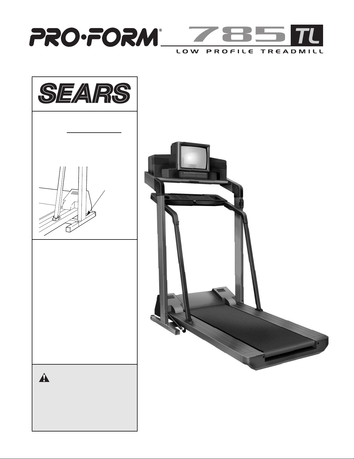
USER'S MANUAL
CAUTION
Read all precautions and instructions in this manual before using
this equipment. Save this manual
for future reference.
Model No. 831.297860
Serial No.
The serial number is found in the location
shown below. Write the serial number in
the space above for future reference.
Serial
Number
Decal
Page 2

2
TABLE OF CONTENTS
IMPORTANT PRECAUTIONS . . . . . . . . . . . . . . . . . . . . . . . . . . . . . . . . . . . . . . . . . . . . . . . . . . . . . . . . . . . . . . . . .2
BEFORE YOU BEGIN . . . . . . . . . . . . . . . . . . . . . . . . . . . . . . . . . . . . . . . . . . . . . . . . . . . . . . . . . . . . . . . . . . . . . . .6
ASSEMBLY . . . . . . . . . . . . . . . . . . . . . . . . . . . . . . . . . . . . . . . . . . . . . . . . . . . . . . . . . . . . . . . . . . . . . . . . . . . . . . .7
GROUNDING INSTRUCTIONS . . . . . . . . . . . . . . . . . . . . . . . . . . . . . . . . . . . . . . . . . . . . . . . . . . . . . . . . . . . . . . . .9
CONSOLE OPERATION . . . . . . . . . . . . . . . . . . . . . . . . . . . . . . . . . . . . . . . . . . . . . . . . . . . . . . . . . . . . . . . . . . . .10
TELEVISION OPERATION . . . . . . . . . . . . . . . . . . . . . . . . . . . . . . . . . . . . . . . . . . . . . . . . . . . . . . . . . . . . . . . . . .16
HOW TO FOLD AND MOVE THE TREADMILL . . . . . . . . . . . . . . . . . . . . . . . . . . . . . . . . . . . . . . . . . . . . . . . . . .23
TROUBLE-SHOOTING . . . . . . . . . . . . . . . . . . . . . . . . . . . . . . . . . . . . . . . . . . . . . . . . . . . . . . . . . . . . . . . . . . . . .25
CONDITIONING GUIDELINES . . . . . . . . . . . . . . . . . . . . . . . . . . . . . . . . . . . . . . . . . . . . . . . . . . . . . . . . . . . . . . .28
PART LIST . . . . . . . . . . . . . . . . . . . . . . . . . . . . . . . . . . . . . . . . . . . . . . . . . . . . . . . . . . . . . . . . . . . . . . . . . . . . . . .30
ORDERING REPLACEMENT PARTS . . . . . . . . . . . . . . . . . . . . . . . . . . . . . . . . . . . . . . . . . . . . . . . .BACK COVER
FULL 90 DAY WARRANTY . . . . . . . . . . . . . . . . . . . . . . . . . . . . . . . . . . . . . . . . . . . . . . . . . . . . . . . .BACK COVER
Note: An EXPLODED DRAWING is attached to the center of this manual. Please save the EXPLODED
DRAWING for future reference.
1. It is the responsibility of the owner to ensure
that all users of this treadmill are adequately
informed of all warnings and precautions.
2. Use the treadmill only as described in this
manual.
3. The treadmill is intended for home use only.
Do not use the treadmill in any commercial,
rental, or institutional setting.
4. Place the treadmill on a level surface, with
eight feet of clearance behind it. All parts of
the treadmill must be at least one foot from
the nearest wall. To protect the floor or carpet
from damage, place a mat under the treadmill.
5. Slots and openings in the treadmill and TV
are provided for ventilation, to ensure reliable
operation, and to help prevent overheating.
These openings must not be blocked or covered. Do not place the treadmill on any surface that blocks openings, or near a radiator
or other heat source.
6. Keep the treadmill indoors, away from moisture and dust. Do not place the treadmill in a
garage or covered patio, or near water.
7. Do not operate the treadmill where aerosol
products are used or where oxygen is being
administered.
WARNING: To reduce the risk of burns, fire, electric shock, or injury to persons, read all
important precautions and information in this manual before operating the treadmill or the television.
IMPORTANT PRECAUTIONS
Page 3

3
8. You must be able to safely lift 45 pounds (20
kg) in order to raise or lower the treadmill.
9. Keep children and pets away from the treadmill at all times.
10. The treadmill should not be used by persons
weighing more than 250 pounds.
11. Never allow more than one person on the
treadmill at a time.
12. Wear appropriate exercise clothing when
using the treadmill. Do not wear loose clothing that could become caught in the treadmill. Athletic support clothes are recommended for both men and women.
13. Always wear athletic shoes when using the
treadmill. Never use the treadmill with bare
feet, wearing only stockings, or in sandals.
14. Inspect and tighten all parts of the treadmill
every three months.
15. The treadmill operates on 120 V, 60 Hz, AC
power only. Consult your dealer before connecting the treadmill if you do not know the
AC voltage in your area, as incorrect voltage
might damage the treadmill or TV. Never connect the treadmill to other than the specified
voltage such as 50 Hz or to direct current.
16. When connecting the power cord (see HOW
TO PLUG IN THE POWER CORD on page 9),
plug the power cord into a surge protector
(not included) and plug the surge protector
into a grounded circuit capable of carrying 15
or more amps. No other appliance should be
on the same circuit. Do not overload wall outlets as this can result in a risk of electric
shock, fires and other hazards.
17. Use only a UL-listed surge protector, rated at
15 amps, with a 14-gauge cord of five feet or
less in length. Do not use an extension cord.
18. The power cord and surge protector should
be positioned so they are not likely to be
walked on or pinched by items placed upon
or against them, paying particular attention to
the cords at the plugs, convenience receptacles, and the point where the power cord
exits the treadmill. Keep the power cord and
surge protector away from heated surfaces.
19. Do not operate the treadmill if the power cord
or plug is damaged or if the treadmill is not
working properly. (See BEFORE YOU BEGIN
on page 6 if the treadmill is not working properly.)
20. If an outside antenna or cable system is
connected, be sure that the antenna or cable
system is grounded so as to provide some
protection against voltage surges and builtup static charges. Section 810 of the National
Electrical Code, ANSI/NFPA No. 70-1984,
provides information with respect to proper
grounding of the mast and supporting structure, grounding of the lead-in wire to an
antenna discharge unit, size of grounding
conductors, location of antenna discharge
unit, connection to grounding electrodes, and
requirements for the grounding electrode.
21. An outside antenna system should not be located in the vicinity of overhead power lines
or other electric light or power circuits, or
where it can fall into such power lines or circuits. When installing an outside antenna
system, extreme care should be taken to
keep from touching such power lines or circuits as contact with them might be fatal.
22. Never start the treadmill while you are standing on the walking belt. Always hold the
handrails while using the treadmill.
23. The treadmill is capable of high speeds.
Adjust the speed in small increments to avoid
sudden jumps in speed.
24. To reduce the possibility of the treadmill
overheating, do not operate the treadmill continuously for longer than one hour.
25. Never leave the treadmill unattended while it
is running. Move the on/off switch to the ÒoffÓ
position when the treadmill is not in use.
26. To protect the treadmill and TV during lightning storms, unplug the power cord from the
wall outlet and disconnect the antenna or
cable system. This will prevent damage due
to lightning and power line surges.
27. Do not push objects through any openings in
the treadmill or TV as they may touch dangerous voltage points or short out parts that
could result in fire or electric shock. Never
Page 4
4
spill or spray any type of liquid into the treadmill or TV.
28. Unplug the treadmill from the wall outlet
before cleaning. Do not use liquid cleaners or
aerosol cleaners. Use a damp cloth for
cleaning.
29. Always unplug the power cord before performing the maintenance and adjustment
procedures described in this manual. Never
remove the motor hood unless instructed to
do so by an authorized service representative. Servicing other than the procedures in
this manual should be performed by an authorized service representative only.
30. To reduce the risk of electric shock, do not
remove the cover or back of the TV. There are
no user serviceable parts inside. Refer servicing to qualified service personnel.
31. The graphic symbols on the back cover of the
TV mean the following:
The lightning flash with arrowhead symbol within an equilateral triangle is intended to alert
the user to the presence of uninsulated Òdangerous voltageÓ within the TVÕs
enclosure that may be of sufficient magnitude
to constitute a risk of electric shock to persons.
The exclamation point within an
equilateral triangle is intended to
alert the user to the presence of
important operating and maintenance (servicing) instructions in this manual.
32. Unplug the treadmill from the wall outlet and
refer servicing to qualified service personnel
under the following conditions:
¥ When the power cord or plug is damaged.
¥ If liquid has been spilled, or objects have
fallen into the treadmill.
¥ If the treadmill has been exposed to water.
¥ If the treadmill or TV does not operate nor-
mally when the operating instructions are
followed. Adjust only those controls that
are covered by the operating instructions,
as improper adjustment of other controls
may result in damage and will often require
extensive work by a qualified technician to restore normal operation.
¥ If the treadmill has been dropped.
¥ When the treadmill exhibits a distinct
change in performance.
33. When replacement parts are required, be sure
the service technician uses replacement
parts specified by the manufacturer or those
that have the same characteristics as the
original part. Unauthorized substitutions may
result in fire, electric shock, or other hazards.
34. Upon completion of any service or repairs to
the treadmill or TV, ask the service technician
to perform safety checks to determine that
the unit is in proper operating condition (refer
to the drawing at the top of page 5).
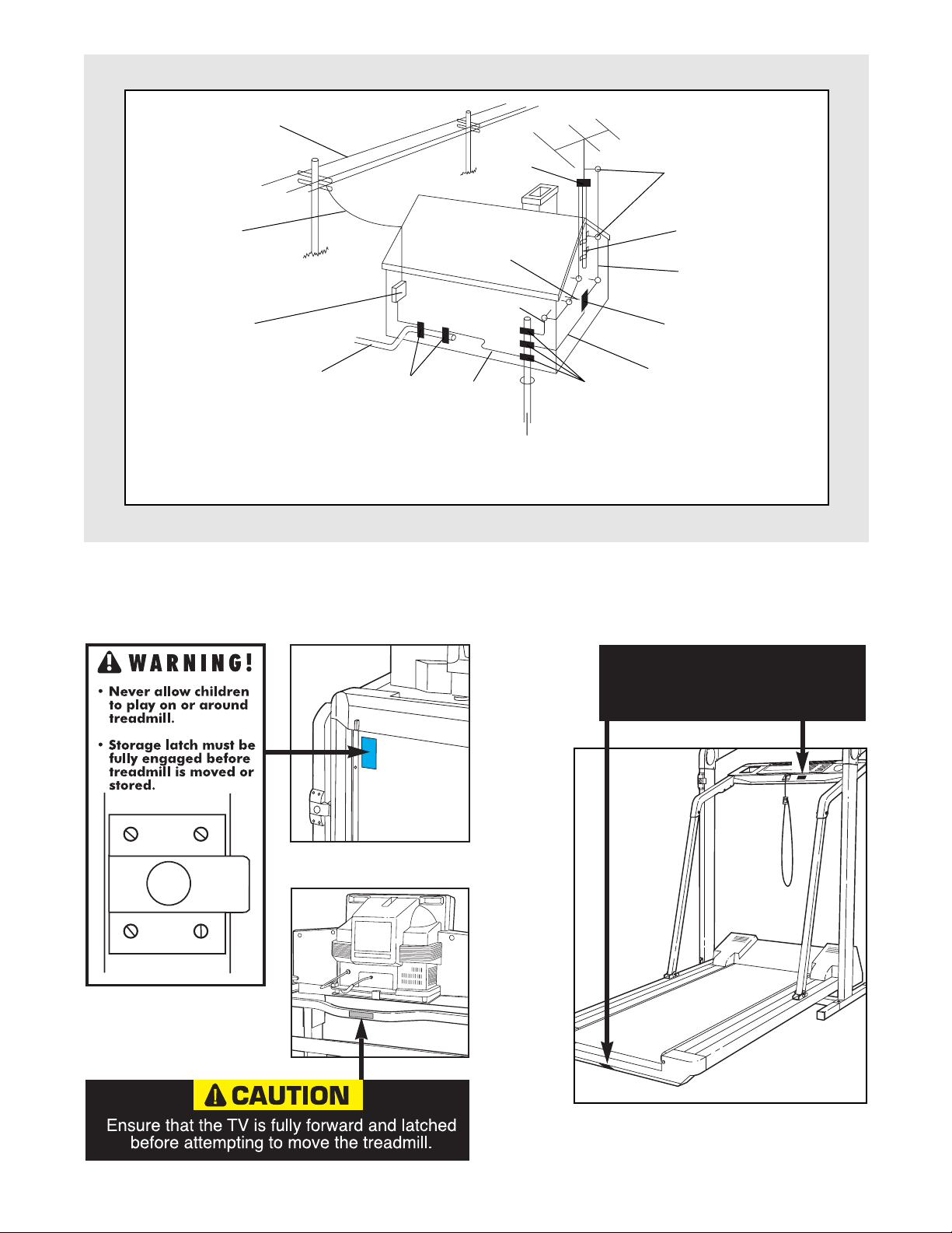
¥ Use No. 10 AWG (5.3mm2) copper, No. 8
AWG (8.4mm2) aluminum, No. 17 AWG
(1.0mm2) copper-clad steel or bronze wire,
or larger as a ground wire.
¥ Secure antenna lead-in and ground wires to
house with stand-off insulators spaced
from 4 to 6 feet (1.22 to 1.83m) apart.
¥ Mount antenna discharge unit as close as
possible to where the lead-in enters the
house.
¥ Use jumper wire not smaller than No. 6
AWG (13.3mm2) copper, or the equivalent
when a separate antenna-grounding electrode is used. See NEC Section 810-21 (j).
Note to CATV system installer: This reminder is
provided to call the CATV system installerÕs attention to Article 820-40 of the NEC that provides
guidelines for proper grounding and, in particular, specifies that the cable ground shall be connected to the grounding system of the building,
as close to the point of cable entry as practical.
WARNING: Before beginning this or
any exercise program, consult your physician.
This is especially important for persons over the
age of 35 or persons with pre-existing health
problems. Read all instructions before using.
SEARS assumes no responsibility for personal
injury or property damage sustained by or
through the use of this product.
SAVE THESE INSTRUCTIONS
Page 5
5
Power Lines
Ground
Clamps
Ground
Clamps
Ground
Clamp
Bonding
Jumper
Standoff
Insulators
Antenna
Lead-in Wire
Ground Wire
Ground
Wire
Antenna
Discharge Unit
To External Antenna
Terminal of Treadmill
Mast
Service
Entrance
Equipment
Power Service Grounding
Electrode System (e.g.
Interior Metal Water Pipe)
Optional Antenna Grounding Electrode Driven 8
Feet (2.44m) Into The Earth (If Required By Local
Codes). See NEC Section 810Ð21 (f).
Service
Entrance
Conductors
IMPORTANT: Incline must be at
lowest level before
folding treadmill into
storage position.
The decals shown below are found in the indicated locations on the treadmill. If a decal is missing, or if it is not
legible, please call our toll-free HELPLINE to order a free replacement decal (see the back cover of this
manual). Apply the decal in the indicated location.
Page 6
6
Congratulations for selecting the revolutionary
PROFORM¨785 TL treadmill. The PROFORM 785 TL
offers an impressive array of features designed to provide an excellent form of cardiovascular exercise in the
convenience and privacy of your home. And when
youÕre not exercising, the unique PROFORM 785 TL
can be folded up, requiring less than half the floor
space of other treadmills.
For your benefit, read this manual carefully before
using the treadmill. If you have additional questions,
please call our toll-free HELPLINE at 1-800-736-6879,
Monday through Saturday, 7 a.m. until 7 p.m. Central
Time (excluding holidays). To help us assist you,
please note the product model number and serial number before calling. The model number of the treadmill
is 831.297860. The serial number can be found on a
decal attached to the treadmill (see the front cover of
this manual for the location).
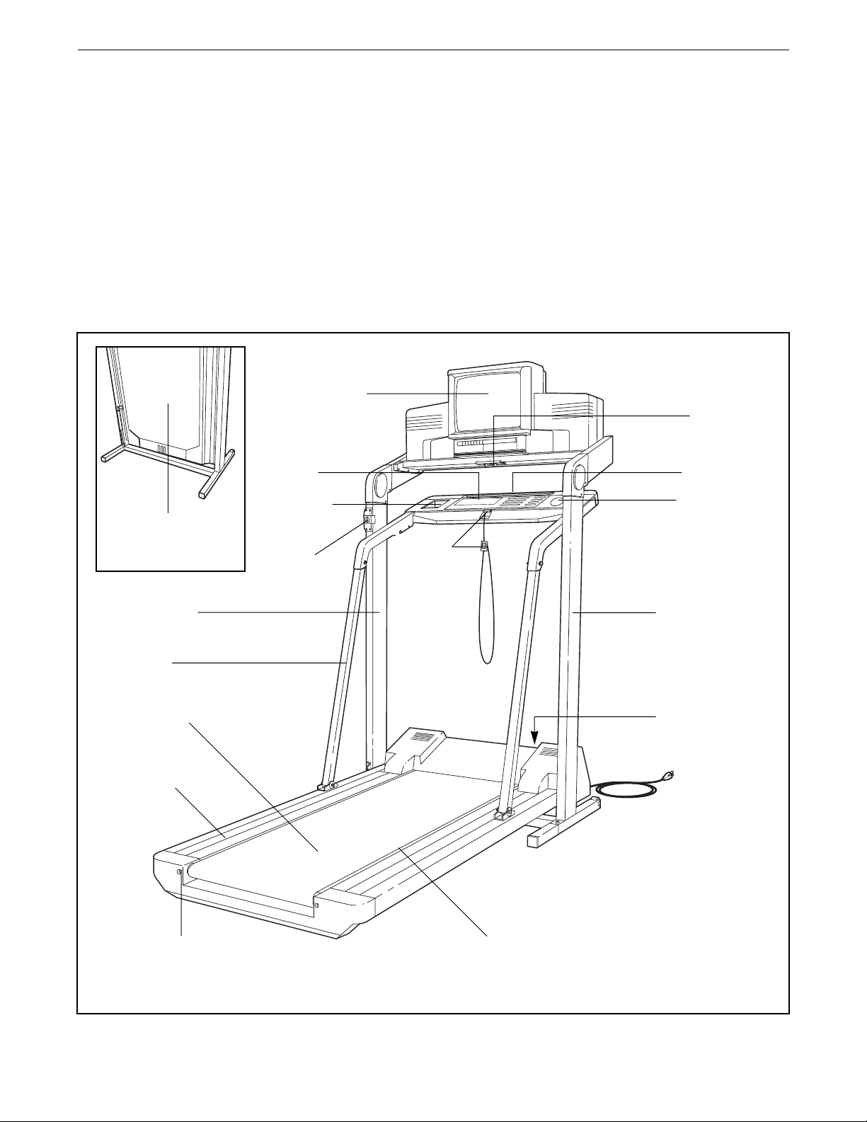
Before reading further, please review the drawing
below and familiarize yourself with the parts that are
labeled.
BEFORE YOU BEGIN
Color Television
Key/Clip
Circuit Breaker,
On/off Switch,
75 Ohm Terminal
Handrails
Walking Belt
Cushioned
Walking Platform
Foot Rails
RIGHT SIDE
LEFT SIDE
Rear Roller
Adjustment Bolt
Console
Storage
Latch
Lock Tabs
Accessory
Tray
Water Bottle
Holder (Water
Bottle is not
included)
Towel Rack
Woodgrain-Finish
Cover Panel
(See page 23)
Page 7
ASSEMBLY
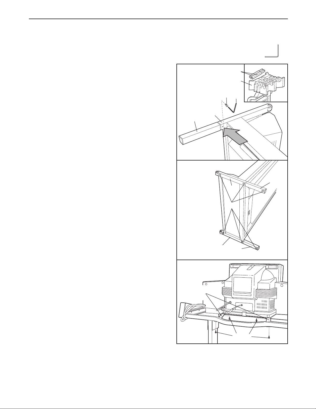
Assembly requires two people. Set the treadmill in a cleared area and remove the packing materials. Do not dispose of the packing materials until assembly is completed. Assembly requires the included allen wrench .
1. See the inset drawing. Remove the Base Extensions (76)
from the packing materials.
Refer to the drawing on page 6 and identify the right
side of the treadmill. With the help of a second person,
carefully lay the treadmill on its right side; do not lay the
treadmill on its left side or the storage latch may be
damaged.
Firmly slide a Base Extension (76) into one side of the
Base (86). Using the Allen Wrench (89), tighten an
Extension Bolt (13) into the Base Extension and the Base.
Attach the other Base Extension (not shown) in the same
manner.
2. Attach six Base Pads (43) to the Base (86) and the Base
Extensions (76) in the indicated locations. Note: One extra
Base Pad may be included.
With the help of a second person, carefully raise the
treadmill to the upright position so the Base (86) and the
Base Extensions (76) are resting on the floor.
3. Locate the two shipping brackets on the back of the tele-
vision. Remove the four indicated screws. Discard the
four screws and the shipping brackets.
76
76
Packing Materials
13
89
86
1
86
86
76
76
43
2
Shipping
Brackets
Screws
3
7
Page 8
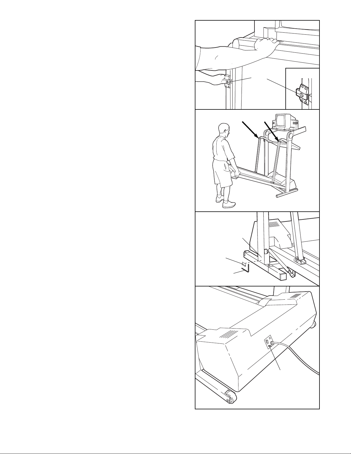
4. Hold the upper end of the treadmill with your right hand
as shown. Using your left thumb, slide open the storage
latch and hold it open. Pivot the treadmill until the frame
is past the storage latch.
5. Hold the treadmill firmly with both hands, and lower the
treadmill to the floor. Caution: To avoid pinching your
hands, do not hold the treadmill in the locations indicated by the arrows. To decrease the possibility of
injury, bend your legs and keep your back straight.
6. Remove the backing from the Adhesive Clip (90). Press
the Adhesive Clip onto the Base (86) in the indicated location. Press the Allen Wrench (89) fully into the Clip.
7. For the console and television to operate properly,
an antenna, a CATV cable, or a VCR must be connected to the 75 ohm antenna terminal on the treadmill (see the drawing at the right).
If you are using an antenna, it must be properly con-
nected and adjusted for optimal reception. Refer to ANTENNA CONNECTIONS on page 17 to properly connect
an antenna.
If you are using a CATV cable, refer to CATV CABLE
CONNECTION on page 17 to properly connect the cable.
If you are using a VCR, refer to HOW TO CONNECT A
VCR on page 22 to properly connect the VCR. The VCR
must be turned on, a videocassette must be properly
inserted, and the VCR must be playing. Refer to your
VCR userÕs manual for operating instructions.
Make sure that all parts of the treadmill are properly tightened. To protect the floor or carpet from damage,
place a mat under the treadmill. Read all instructions in this manual before operating the treadmill.
8
6
86
89
75 Ohm
Antenna
Terminal
90
7
Storage
Latch
Opened
4
Do not hold here
5
Page 9
9
GROUNDING INSTRUCTIONS
THE PERFORMANT LUBETMWALKING BELT
Your treadmill features a walking belt coated with
PERFORMANT LUBETM, a high-performance lubricant.
IMPORTANT: Never apply silicone spray or other
substances to the walking belt or the walking platform; such substances will deteriorate the walking
belt and cause excessive wear.
HOW TO PLUG IN THE POWER CORD
Your treadmill, like any other type of sophisticated
electronic equipment, can be seriously damaged by
sudden voltage changes in your homeÕs power.
Voltage surges, spikes, and noise interference can result from weather conditions or from other appliances
being turned on or off.
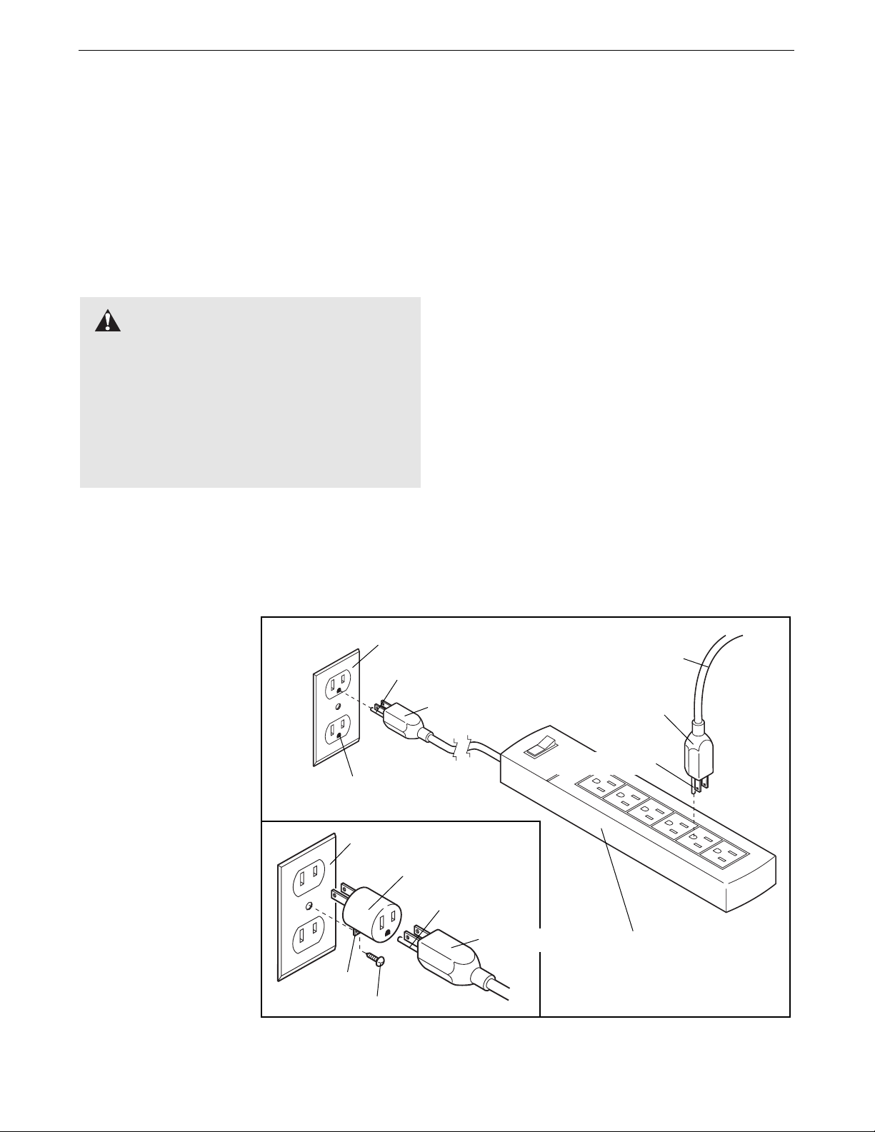
To decrease the possibility of your treadmill being damaged,
always use a surge
protector (not included) with your
treadmill.
Surge protectors are
sold at most hardware
stores and department
stores. Use only a ULlisted surge protector,
rated at 15 amps, with a
14-gauge cord of five
feet or less in length.
This product must be
grounded. If it should
malfunction or break
down, grounding provides a path of least resistance for electric current to reduce the risk of
electric shock. This product is equipped with a cord
having an equipment-grounding conductor and a
grounding plug. Plug the power cord into a surge
protector, and plug the surge protector into an appropriate outlet that is properly installed and
grounded in accordance with all local codes and
ordinances.
This product is for use on a nominal 120-volt circuit,
and has a grounding plug that looks like the plug illustrated in drawing 1 below. A temporary adapter that
looks like the adapter illustrated in drawing 2 may be
used to connect the surge protector to a 2-pole receptacle as shown in drawing 2 if a properly grounded outlet is not available.
The temporary adapter should be used only until a
properly grounded outlet (drawing 1) can be installed
by a qualified electrician.
The green-colored rigid ear, lug, or the like extending
from the adapter must be connected to a permanent
ground such as a properly grounded outlet box cover.
Whenever the adapter is used it must be held in place
by a metal screw. Some 2-pole receptacle outlet box
covers are not grounded. Contact a qualified electrician to determine if the outlet box cover is
grounded before using an adapter.
DANGER: Improper connection
of the equipment-grounding conductor can
result in an increased risk of electric shock.
Check with a qualified electrician or serviceman if you are in doubt as to whether the
product is properly grounded. Do not modify
the plug provided with the productÑif it will
not fit the outlet, have a proper outlet installed by a qualified electrician.
1
2
Grounded Outlet Box
Grounded Outlet Box
Grounding Plug
Treadmill Power Cord
Grounding Plug
Grounding Plug
Grounding Pin
Surge Protector
Grounding Pin
Grounding Pin
Adapter
Lug
Metal Screw
Grounded Outlet
Page 10
Note: If there is a thin sheet of clear plastic
on the face of the console, remove it.
FEATURES OF THE CONSOLE
The revolutionary PROFORM 785 TL offers an impressive array of features designed to make your workouts
more enjoyable and effective.
When the console is in the manual mode, the speed
and incline of the treadmill can be changed with a
touch of a button. As you exercise, the integral color
TV will show your favorite television programs while
displaying instant exercise feedbackÑyou can view
the elapsed time, speed, distance, incline, and numbers of calories and fat calories burned. In addition, the
console offers seven preset workout programs. Each
program is designed to automatically control either the
speed or the incline of the treadmill as it guides you
through an effective workout.
Complete instructions for operating the color TV are
found in the section beginning on page 16 of this manual. To operate the console with the TV, read the instructions on pages 11 to 15.
IMPORTANT: For the console and television to operate properly, an antenna, a CATV cable, or a VCR
must be connected to the 75 ohm antenna terminal
on the front of the motor hood (see assembly drawing 6 on page 8).
If you are using an antenna, it must be properly con-
nected and adjusted for optimal reception. Refer to ANTENNA CONNECTIONS on page 17 to properly connect an antenna.
If you are using a CATV cable, refer to CATV CABLE
CONNECTION on page 17 to properly connect the
cable.
If you are using a VCR, refer to HOW TO CONNECT
A VCR on page 22 to properly connect the VCR.
CAUTION: Before operating the
console, read the following precautions.
¥ Always wear the clip (see the drawing above)
while using the treadmill. If the key is pulled
from the console, the walking belt will stop.
¥ Do not stand on the walking belt when turn-
ing on the power or starting the walking belt.
¥ The treadmill is capable of high speeds.
Adjust the speed in small increments.
¥ To reduce the possibility of the treadmill
overheating, do not operate the treadmill
continuously for longer than one hour.
¥ Never leave the treadmill unattended while it
is running. Move the on/off switch to the ÒoffÓ
position when the treadmill is not in use.
¥ To reduce the risk of electric shock, keep
the console dry, avoid spilling liquids on the
console, and use only a sealed water bottle.
Remove the water bottle from the console
before folding the treadmill for storage.
Clip
Key
Program Profiles
CONSOLE OPERATION
10
Page 11

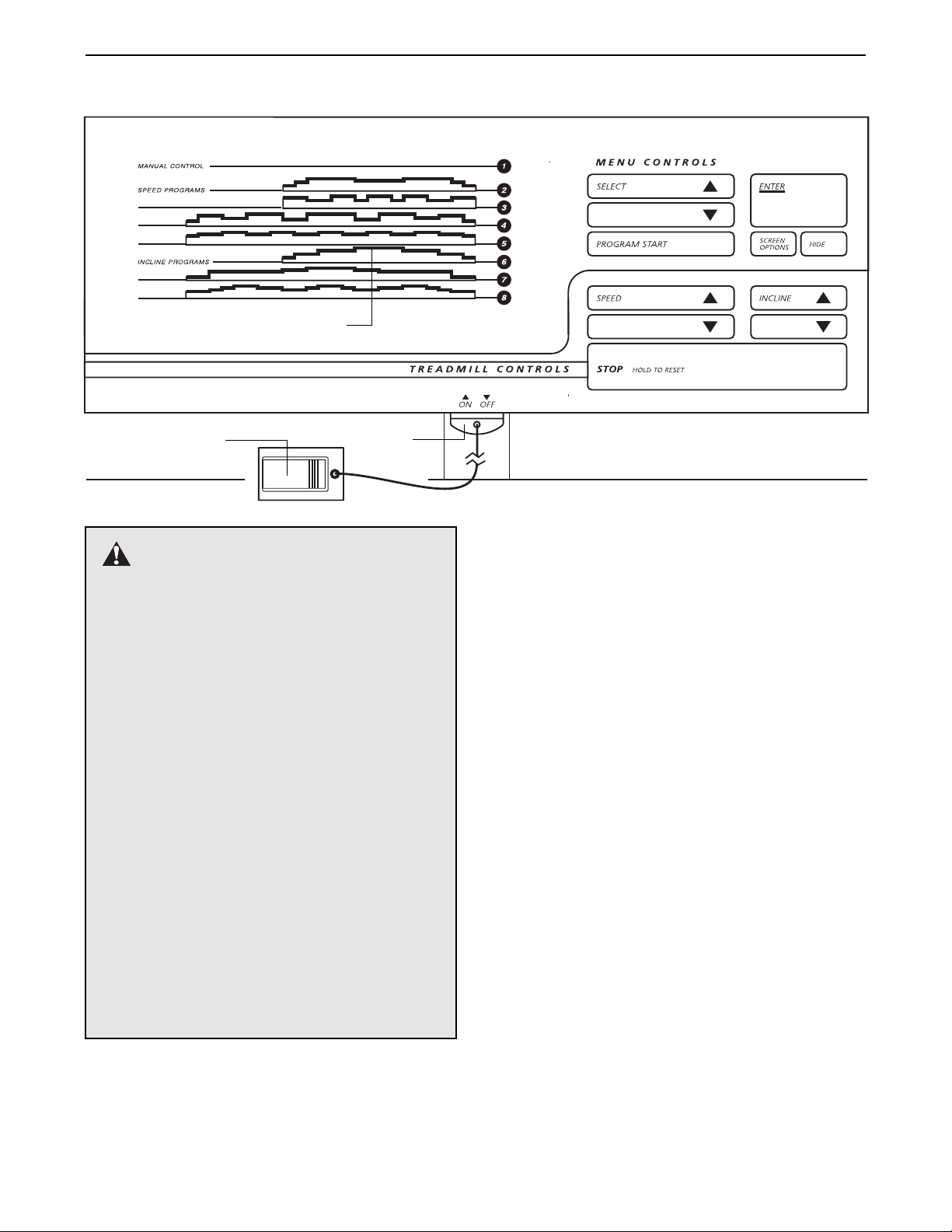
DIAGRAM OF THE CONSOLE
Please refer to the drawing at the top of page 10.
A. Program profilesÑThese profiles show how the
speed or incline of the treadmill will change during
the preset workout programs. During program 6, for
example, the incline will gradually increase during
the first half of the program, and then gradually decrease during the last half.
B. Key and clipÑThis key turns the console on and off.
The attached clip is designed to be worn on your
waistband. If the key is pulled from the console, the
power will automatically turn off.
C. SELECT buttonsÑThese buttons are used to select
the manual mode and the seven preset workout
programs. They are also used to set your weight,
select a maximum speed setting for a speed
program, and select a maximum incline setting for
an incline program.
D. PROGRAM START buttonÑThis button is used to
start preset workout programs.
E. ENTER buttonÑThis button is pressed after you
enter your weight, or select the manual mode or one
of the preset workout programs.
F. SCREEN OPTIONS buttonÑThis button is used to
select the way that exercise feedback is shown on
the TV. There are three different options:
Option 1ÑThe bottom
of the TV screen will
show the elapsed time
and the speed for
seven seconds, the
distance and the incline for seven seconds, and then the
numbers of calories and fat calories burned for
seven seconds (see page 28 for an explanation of
fat calories). The cycle will then repeat. Note: If a
preset program is selected, the speed or incline settings of the program will also be shown.
Option 2ÑThe TV will
simultaneously show
the elapsed time,
speed, incline, distance, and numbers of
calories and fat calories burned.
Option 3ÑThe TV will
show only the speed in
the lower right corner.
Note: If a speed program is selected, the
speed will flash for five
seconds each time the
speed of the walking
belt is about to change.
G. HIDE buttonÑThis button is used to select the way
that the TV screen will appear when exercise feedback is shown. The three modes are described below.
Mode 1ÑThe text will
be displayed over a
normal TV picture.
Mode 2ÑA horizontal
black stripe will appear
behind the text, making it easier to read the
text if the TV picture is
light.
Mode 3ÑA black box
will appear behind the
text, covering the TV
picture.
H. SPEED buttonsÑThese buttons are used to control
the speed of the walking belt. Each time one of the
buttons is pressed, the speed will change by 0.1
mph. The buttons can be held down to change the
speed quickly. The speed range of the walking belt
is 0.5 mph to 10 mph.
I. INCLINE buttonsÑThese buttons are used to control
the incline of the treadmill. Each time one of the buttons is pressed, the incline will change by 0.5%. The
buttons can be held down to change the incline
quickly. The incline range is 1.5% to 10%.
J. STOP buttonÑThis button is used to stop the walk-
ing belt. If the button is pressed briefly, the values of
the six feedback modes will be retained. If the button
is held down for two seconds, the elapsed time,
speed, distance, incline, and numbers of calories
and fat calories will be reset to zero.
7:20
SPEED 6 . 0
11
10.0 MPH
7:20
SPEED 6 . 0
7:20 I 3.5
S 6.0
D 2.7
C122 F 5 2
7:20
SPEED 6 . 0
7:20
SPEED 6 . 0
Page 12

HOW TO USE THE MANUAL MODE
Make sure that the on/off
switch located on the front of
the motor hood is in the ÒonÓ
position. In addition, make sure
that the power cord is properly
plugged in (see page 9).
To turn on the TV, press the POWER button on the TV
or the remote control.
Step onto the foot rails of the treadmill. Find the clip attached to the key, and slide the clip onto the waistband
of your clothing. Follow the steps below to use the
manual mode of the console.
Insert the key into the console.
Note: When you are familiar with the operation of the treadmill,
you may go directly to
step 4 after inserting
the key. While learning
to use the console,
please read and follow
all steps below.
Enter your weight if desired.
A few seconds after
the key is inserted , a
message on the TV
will prompt you to
enter your weight. You
do not have to enter
your weight in order to
use the console; however, the calorie and fat calorie feedback will be
more accurate if you enter your weight.
If you do not wish to enter your weight, press the
ENTER button and go to step 3.
If you wish to enter your weight, press the SELECT
buttons. Each time one of the buttons is pressed,
the weight shown on the TV will change by 1 pound.
The buttons can be held down to enter your weight
quickly. When the correct weight is shown on the
TV, press the ENTER button.
Select the manual mode.
A message on the TV
will prompt you to select a program. To use
the manual mode, the
arrow on the TV
should point to the
number 1 (see the
drawing at the right). If the arrow is pointing to a different number, press the SELECT buttons repeatedly
until the arrow points to the number 1. Then press the
ENTER button.
Note: To select a preset program, see HOW TO USE
A PRESET WORKOUT PROGRAM on page 13.
Start the walking belt.
A message on the TV
will prompt you to adjust the speed of the
walking belt. The
speed of the walking
belt is controlled with
the SPEED buttons.
Each time one of the buttons is pressed, the speed
will change by 0.1 mph. The buttons can be held
down to change the speed quickly. The speed
range of the walking belt is 0.5 to 10 mph.
Press the SPEED increase button once. The walking
belt will begin to move at 1.0 mph. Hold the
handrails and begin walking. Change the speed of
the walking belt as desired by pressing the SPEED
buttons. Note: Any time that the SPEED buttons are
pressed, the TV will show the speed setting for
seven seconds.
To stop the walking belt, press the STOP button.
The information shown on the TV will begin to flash.
To restart the walking belt, press the SPEED buttons. Note: To stop the walking belt and reset the
elapsed time, speed, distance, incline, and numbers
of calories and fat calories to zero, hold down the
STOP button for two seconds.
Adjust the incline if desired.
The incline of the treadmill is controlled with the INCLINE buttons. Each time one of the buttons is
pressed, the incline will change by 0.5%. The buttons can be held down to change the incline quickly.
The incline range is 1.5% to 10%. Note: After the
buttons are pressed, it may take a few seconds for
the treadmill to reach the selected incline setting.
Any time that the INCLINE buttons are pressed, the
TV will show the incline setting for seven seconds.
1
2
3
4
5
Arrow
OFF
ON
ÒOnÓ
Position
12
SELECT YOUR WEIGHT
150 LBS
THEN PRESS ENTER.
SELECT
PROGRAM
THEN
PRESS
ENTER.
1
MANUAL
2
SPD
3
SPD
4
SPD
SPD
5
INCL
6
INCL
7
INCL
8
ADJUST SPEED
0:00
SPEED 0 . 0
MTN
PLAT
INTR
INTR
MTN
PLAT
INTR
Page 13

Follow your progress with the exercise feedback
shown on the TV.
As you exercise, the
TV will display the
elapsed time and the
speed for seven seconds, the distance and
the incline for seven
seconds, and then the
numbers of calories
and fat calories burned for seven seconds. The
cycle will then repeat.
By pressing the SCREEN OPTIONS and HIDE buttons, you can modify the way that exercise feedback
is shown on the TV. The different options are described on page 11 (see F and G).
When you are finished exercising, stop the walking belt and remove the key.
Step onto the foot rails, stop the walking belt, and remove the key from the console.
IMPORTANT: The
treadmill must be at
the lowest incline
level before it is
folded for storage. If
the treadmill is not at
the lowest incline
level when the key is
removed, a message will appear for twenty seconds on the TV and will prompt you to press the
ENTER button to lower the treadmill.
When the treadmill is
at the lowest incline
level, a message on
the TV will verify that
the treadmill is ready to
be folded.
After removing the key, be sure to store it in a secure
place. Move the on/off switch to the ÒoffÓ position.
(See the drawing in the upper right corner of this
page.)
To turn off the TV, press the POWER button on the
TV or the remote control.
HOW TO USE A PRESET WORKOUT PROGRAM
Make sure that the on/off
switch located on the front of
the motor hood is in the ÒonÓ
position. In addition, make sure
that the power cord is properly
plugged in (see page 9).
To turn on the TV, press the POWER button on the TV or
the remote control.
Step onto the foot rails of the treadmill. Find the clip attached to the key, and slide the clip onto your waistband.
Follow the steps below to use a preset workout program.
Insert the key into the console.
Enter your weight if desired.
A few seconds after
the key is inserted, a
message on the TV
will prompt you to
enter your weight.
You do not have to
enter your weight in
order to use the console; however, the calorie and fat calorie feedback
will be more accurate if you enter your weight.
If you do not wish to enter your weight, press the
ENTER button and go to step 3.
If you wish to enter your weight, press the SELECT
buttons. Each time one of the buttons is pressed,
the weight shown on the TV will change by 1 pound.
The buttons can be held down to enter your weight
quickly. When the correct weight is shown on the
TV, press the ENTER button.
Select a preset program.
A message on the TV
will prompt you to select a program. Press
the SELECT buttons
repeatedly until the
arrow points to the
desired program.
Then press the
ENTER button.
7
6
1
2
3
Arrow
OFF
ON
ÒOnÓ
Position
13
7:20
SPEED 6 . 0
PRESS ENTER TO
REDUCE INCLINE
BEFORE FOLDING
TREADMILL IS
READY TO FOLD
FOR STORAGE
SELECT YOUR WEIGHT
150 LBS
THEN PRESS ENTER.
SELECT
PROGRAM
THEN
PRESS
ENTER.
MANUAL
1
SPD
2
SPD
3
SPD
4
SPD
5
INCL
6
INCL
7
INCL
8
MTN
PLAT
INTR
INTR
MTN
PLAT
INTR
Page 14

Programs 2, 3, 4, and 5 are speed programsÑthe
console will automatically control the speed of the
walking belt as you control the incline. Programs 6, 7,
and 8 are incline programsÑthe console will control
the incline of the treadmill as you control the speed.
The profiles on the left side of the console show how
the speed or incline will change during the programs.
During program 6, for example, the incline will gradually increase during the first half of the program, and
then gradually decrease during the last half. Programs 2, 3, and 6 are twenty-minutes programs;
programs 4, 5, 7, and 8 are thirty-minute programs.
Select a maximum speed or incline setting.
If you selected a
speed program (pro-
grams 2, 3, 4, or 5), a
message on the TV will
prompt you to select
the maximum speed
that you want the walking belt to move during
the program. Press the SELECT buttons to select a
maximum speed setting. Each time one of the buttons is pressed, the setting will change by 0.5 mph.
The setting must be between 2.5 mph and 10 mph.
If you selected an
incline program (pro-
grams 6, 7, or 8), a
message on the TV
will prompt you to select the maximum incline that you want the
treadmill to reach during the program. Press the SELECT buttons to select a maximum incline setting. Each time one of the
buttons is pressed, the setting will change by 0.5%.
The setting must be between 6.5% and 10%.
Press the PROGRAM START button.
When the PROGRAM
START button is
pressed, a program
profile will be shown
on the TV for three
seconds to show the
speed or incline settings of the program
you selected.
After three seconds,
the TV will display the
information shown at
the right. The word
ÒWARMÓ will flash to
indicate that the warmup period of the program has begun.
(Each program begins with a one-minute warm-up period, and ends with a one-minute cool-down period.)
The white indicators to the right show upcoming speed
or incline settings. The numbers at the right side of the
TV show the maximum and minimum speed or incline
settings of the program. The letter ÒSÓ or ÒIÓ shows
whether a speed or incline program is selected.
A few seconds after the PROGRAM START button
is pressed, the walking belt will begin to move. Hold
the handrail and begin walking on the walking belt.
After the warm-up period is completed, the
TV will display the information at the right.
The flashing white indicator will show the
current speed or incline setting. The
white indicators to the right show upcoming speed or
incline settings. The dashes to the left show the most
recent speed or incline settings. As the program progresses, the white indicators will move to the left and
the speed or incline of the treadmill will automatically
change as shown by the white indicators.
If a speed program is selected, the incline of the
treadmill can be changed at any time during the program with the INCLINE buttons. If an incline program is selected, the speed of the walking belt can
be changed at any time with the SPEED buttons.
During the last minute of the program, the word
ÒcoolÓ will flash on the TV to indicate that the cooldown period of the program is in progress. During
the last ten seconds of the program, the incline of
the treadmill will automatically decline to the lowest
incline level. The walking belt will then slow to a
stop and the program will be completed.
Note: If the program is too easy or too challenging,
the maximum speed or incline setting can be adjusted by pressing the SPEED or INCLINE buttons.
The new maximum and minimum settings will be
shown on the TV. To pause the program, press the
STOP button. The exercise feedback shown on the
TV will begin to flash. When you are ready to restart
the program, press the PROGRAM START button.
To terminate the program before it is completed,
hold down the STOP button for two seconds.
4
5
SELECT MAX. SPEED
10.0 MPH
THEN PRESS START.
Max.
Min.
Profile
Current
Setting
14
SELECT MAX INCLINE
6 . 5 PERCENT
THEN PRESS START.
W
A
R
M
20:00
10.0
SPEED 0 . 0
.
.
S
.
.55
20:00
10.0
SPEED 0 . 0
.
.
S
.
.55
10.0
0:00 SPEED 0 . 0
.
.
.
S
.
.55
Page 15

15
Follow your progress during the program with
the exercise feedback shown on the TV.
As you exercise, the
TV will display the
elapsed time and the
speed for seven seconds, the distance
and the incline for
seven seconds, and
then the numbers of
calories and fat calories burned for seven seconds.
The cycle will then repeat.
By pressing the SCREEN OPTIONS and HIDE buttons, you can modify the way that exercise feedback
is shown on the TV. The different options are described on page 11 (see F and G). Note: The white indicators and other program information will be shown
on the TV only when screen option 1 is selected.
When you are finished exercising, stop the walking belt and remove the key.
Step onto the foot rails and remove the key from the
console. A message on the TV will verify that the
treadmill is ready to be folded.
After removing the key, be sure to store it in a secure place. Move the on/off switch to the ÒoffÓ position. (See the drawing near the top of page 13.)
To turn off the TV, press the POWER button on the
TV or the remote control.
HOW TO SELECT THE INFORMATION MODE
The console features an information mode that lets you
modify the format of text displayed on the TV and shows
the total time and distance accumulated on the treadmill.
To access the information mode, first make sure that
the on/off switch located on the front of the motor hood
is in the ÒonÓ position. In addition, make sure that the
power cord is properly plugged in (see page 9). Press
the POWER button on the TV or the remote control to
turn the TV on.
Next, hold down the STOP button, insert the key into
the console, and continue holding down the STOP button until the TV displays
the information shown at
the right. When single
lines of text are displayed
on the TV, the text can
appear at either the bottom or the top of the
screen. To change the position of the text, press the
SELECT buttons. The words ÒBOTTOM LINEÓ or ÒTOP
LINEÓ will show which setting is selected. To see more
user information, press the ENTER button.
After the ENTER button
is pressed, the TV will
show the total number of
hours that the treadmill
has been used, and the
total number of miles
that the walking belt has
moved. (Note: When the
total number of hours exceeds 999, it will reset to zero;
when the total number of miles exceeds 99,999, it will
reset to zero.) To see more user information, press the
ENTER button.
If the text displayed on
the TV is too far to the
right or left side of the
screen, the text can be
centered. To center the
text, press the SELECT
buttons while the message at the right appears on the TV.
To exit the information mode at any time, press the
STOP button.
HOW TO ADJUST THE POSITION OF THE TV
The TV can be adjusted to any of four positions for the
most comfortable viewing. To adjust the position,
squeeze the
lock tabs under
the TV, slide
the TV forward
or backward,
and release the
tabs. Move the
TV slightly forward or backward to make
sure that it is
locked in position.
7
SELECT OPTION
TOP LINE
PRESS STOP TO EXIT
OR ENTER TO CONTINUE
6
7:20
SPEED 6 . 0
Lock Tabs
HISTORY
10 HOURS
49 MILES
PRESS STOP TO EXIT
OR ENTER TO CONTINUE
USE SELECT ARROWS
TO ADJUST TEXT
LEFT OR RIGHT
PRESS STOP TO EXIT
OR ENTER TO CONTINUE
Page 16

¥ Blackstripe Picture Tube
¥ 181 cable ready channels (68 standard TV channels
plus 113 cable channels)
¥ Full-featured on-screen display
¥ User-friendly menu-driven TV controls
¥ Video and audio input jacks
¥ Full-function 27-key infrared remote control
¥ Real time clock with 1 on-timer and 1 off-timer
¥ Sleep timer (10 to 120 minutes selectable)
¥ Mono audio
¥ Earphone jack (Mono)
¥ LED power indicator
¥ Built-in closed caption decoder for hearing impaired
¥ Auto memory and auto search for TV channel
¥ Automatically skips unavailable channels in your area
Note: The TV can be viewed without the treadmill being
used. The on/off switch near the power cord must be in
the ÒonÓ position. (See the drawing at the top of page 13.)
1. Infrared Remote
Sensor
2. Power Indicator*
3. Power On/Stand-
by Button
4. Channel Æ/
Buttons
5. Volume +/Ð
Buttons
6. Compartment
Door
7. TV/CATV Button
8. TV/AV Button
9. Pop-up Menu
Button
10. Earphone Jack
*Whenever the indicator is on, the remote control can be
used to control the TV, even if the key is not in the console.
IMPORTANT: The treadmill and TV, like any other
electronic equipment, can be damaged by static
electricity. Before plugging in earphones (not
included) or touching the controls behind the
compartment door, touch one of the treadmill
handrails to discharge static electricity.
1. TV/CATV Channel Selection
ButtonsÑUsed
to select a channel by keying in
the channel
number.
2. TV/CATV Select
ButtonÑUsed to
toggle between
TV and cable TV
channels.
3. TV/AV Select
ButtonÑUsed to
select between
TV and video
input.
4. TIMER Select ButtonÑUsed to adjust menu-driven
real time clock, on timer, and off timer. Used together with +/Ð buttons.
5. Closed Caption Select ButtonsÑUsed to select
CCD On/Off, C1, C2, and CCD Text.
6. Pop-up MENU ButtonÑUsed to select channel
memory timer and analog select menu.
7. VOLUME +/Ð ButtonsÑUsed to adjust the volume
level and picture levels.
8. POWER ButtonÑUsed to turn the TV on and off.
9. CHANNEL Æ/ ButtonsÑUsed to step through favorite channels from the memory of the TV.
10. SLEEP Timer ButtonÑPress once to display the
sleep time. Press again to change and activate the
sleep timer.
11. Channel/Time DISPLAY ButtonÑUsed to display
the current channel number and time on the screen.
12. MUTE ButtonÑPress once to turn off the volume.
Press again to restore the volume.
13. ANALOG SELECT ButtonÑUsed to select which
picture level (contrast, brightness, color, or tint) you
want to adjust. Used together with the +/Ð buttons.
Æ
Æ
TELEVISION OPERATION
FEATURES OF THE TELEVISION DIAGRAM OF THE REMOTE CONTROL
DIAGRAM OF THE TELEVISION
1
2
3
5
64
7
8
9
10
1
8
10
9
11
12
13
2
3
5
+
-
6 7
4
16
Page 17

Indoor Antenna
1. Place the VHF
antenna in the
desired location. Connect
the 300 ohm
flat wire to the
screws on the
300 ohm to 75
ohm adapter.
2. Connect the
300 to 75 ohm
adapter to the
75 ohm antenna terminal
on the treadmill.
(See assembly
drawing 6 on
page 8 for the
location of the
terminal.)
Outdoor Antenna
Outdoor antennas are subject to weathering that can
reduce signal quality. Inspect the antenna and lead-in
wiring before connecting the antenna. Any service center can explain the various outdoor antennas available.
¥ 300 Ohm Flat Wire
1. Refer to the drawing above. Connect the 300 ohm
flat wire to the 300 ohm to 75 ohm adapter.
2. Push the end of the 300 ohm to 75 ohm adapter
into the 75 ohm antenna terminal on the treadmill.
(See assembly drawing 6 on page 8 for the location of the terminal.)
¥ 75 Ohm Coaxial Cable
Refer to the drawing in the lower left corner of this page.
Connect the 75 ohm coaxial cable directly to the 75 ohm
antenna terminal on the treadmill. (See assembly drawing 6 on page 8 for the location of the terminal.)
1. Remove the VHF 300 to 75 ohm adapter or the VHF
cable from the antenna terminal.
2. Connect the CATV
cable (75 ohm coaxial
cable) to the 75 ohm
antenna terminal on the
treadmill. (See assembly drawing 6 on page 8
for the location of the
terminal.)
Read the important precautions on pages 2 to 5 of
this manual. Before operat-
ing the TV, make sure that the
on/off switch located on the
front of the motor hood is in
the ÒonÓ position, and that the
power cord is properly
plugged in (see page 9).
Battery Installation
Before the remote
control can be operated, two ÒAAAÓ
batteries (included)
must be installed.
Slide the battery
cover off the back
of the remote control. Press two batteries into the remote control. Make
sure that the batteries are turned
as shown.
Reattach the battery cover.
300 to 75 Ohm Adapter
Screwdriver
VHF 300
Ohm Flat
Wire
75 Ohm
Terminal
300 to 75 Ohm
Adapter
VHF Rod
Antenna
Combination
VHF/UHF Antennas
300 Ohm
Flat Wire
75 Ohm
Terminal
on Treadmill
300 to 75
Ohm Adapter
75 Ohm
Coaxial Cable
75 Ohm CATV Cable
75 Ohm CATV Cable
ANTENNA CONNECTIONS
CATV CABLE CONNECTION
BASIC TV OPERATION
ÒOnÓ
Position
ÒAAAÓ Batteries
Battery
Cover
Remote
Control
17
OFF
ON
Page 18

Turning on the Power
To turn on the TV, press the POWER button on the TV
or the remote control.
Volume Control
To adjust the volume to the desired level, press the
VOLUME + or Ð button.
The sound level will be
shown by a bar on the TV
screen. As the sound level
is increased, the bar will
move to the right. As the
sound level is decreased,
the bar will move to the left.
Note: If no broadcasting
signal is received, the sound will be muted and the volume control will be disabled.
Direct Channel Selection (by Remote Control)
Use the channel selection
buttons on the remote control to select a channel
number. The channel number will appear on the upper
right corner of the TV
screen. For channels 2
through 9, press the 0 button and then press the desired channel number (if the
0 button is not pressed first,
channel selection will be
delayed for 3 seconds). For channels 10 through 99,
press the two digits in order. Be sure to press the second digit within 3 seconds after pressing the first. For
CATV channels over 100, press the 1-- button first and
then press the desired channel numbers.
Skip Mode
Press the CHANNEL Æ or button to select memorized channels, skipping over empty channels. Hold
down the CHANNEL Æ or button to change channels
continuously. Note: If no channels are memorized, the
TV will switch to the SEARCH mode.
Search Mode
Press the CHANNEL Æ or button to search for the
next available channel. Hold down the CHANNEL Æ or
button to search through all available channels.
Note: Before selecting channels with the CHANNEL Æ
or button, the channels must be set into the TVÕs
memory. See MEMORIZING CHANNELS at the right.
Memorizing Channels
The TV is equipped with a channel memorizing function
that allows you to step up or down from the current
channel to the next channel set into memory. Before
channels can be selected in this way, they must be set
into the TVÕs memory. Note: When programming channels, if no buttons are pressed for four seconds, the TV
will return to the normal screen.
Automatic Memory Tuning
1. Press the MENU button to
turn on the pop up menu in
the TV mode or CATV
mode. Press the MENU
button again to select CH
MEMORY (channel memory).
2. Press the MENU button
again to select AUTO
MEMORY.
3. Press the + button to start
AUTO MEMORY. The TV
will begin setting into
memory all the channels
available in your area.
When no broadcast signal
is detected on a channel,
the channel is erased from
memory. When a signal is detected, the channel is
stored in memory and the next channel is selected.
This process will be repeated until the highest
channel is reached. It then
stops at the lowest channel
stored in memory, and returns to a normal screen
after four seconds. The TV
will then be in the SKIP
mode.
Æ
Æ
Æ
Æ
Æ
CHANNEL PROGRAMMING
CH MEMORY
ANALOG
CLOCK/TIMER
TV 07
AUTO MEMORY
START [+]
TV 07
AUTO MEMORY
END
AUTO MEMORY
SEARCH/SKIP
MEMORY ADD
¥ERASE
TV/CATV
VOLUME
18
Page 19

19
Erasing Channels
After all channels available in your area have been set
into memory, you can erase unwanted channels by following the steps below:
1. Select the unwanted channel by using the CHANNEL
Æ or button or the channel selection buttons.
2. Press the MENU button to
turn on the pop up menu.
Press the MENU button
again to select CH MEMORY.
3. Press the + or Ð button to
move the arrow to MEMORY ADD¥ERASE. Select
MEMORY ADD¥ERASE by
pressing the MENU button.
4. Press the Ð button to
erase the stored channel
from memory. The channel
number will change from
green to red.
Adding Channels
Channels that are not in memory can be stored manually. To manually store a channel, follow the steps
above, but press the + button when MEMORY ADD¥
ERASE is selected. The channel will be stored in memory, and the channel number will change from red to
green.
Manually Searching for and Storing Channels
1. Press the MENU button to
turn on the pop up menu.
Press the MENU button
again to select CH MEMORY.
2. Press the + or Ð button to
move the arrow to
SEARCH/SKIP. Select
SEARCH/SKIP by pressing the MENU button.
3. Press the Ð button to select the SEARCH mode.
The TV will return to the
normal screen after four
seconds.
4. Press the CHANNEL Æ or button to start searching. It will stop whenever an available channel is
found.
5. If you do not want to store the channel in memory,
press the CHANNEL Æ or button again. To store
the channel in memory, refer to ADDING CHANNELS at the left.
6. Until all desired channels have been stored, return to
SEARCH/SKIP as described above and press the +
button to return to the SKIP mode.
Æ
Æ
Æ
CHANNEL UP/DOWN
SKIP : [ + ]
SEARCH : [ Ð ]
CH MEMORY
ANALOG
CLOCK/TIMER
AUTO MEMORY
SEARCH/SKIP
MEMORY ADD
¥ERASE
TV/CATV
TV 07
CHANNEL MEMORY
END ERASE
[ + ] [ Ð ]
CH MEMORY
ANALOG
CLOCK/TIMER
AUTO MEMORY
SEARCH/SKIP
MEMORY ADD
¥ERASE
TV/CATV
Page 20

20
In addition to normal broadcast reception, the TV is
equipped to receive up to 125 cable channels (113 plus
12 TV channels). To use the TV with a cable TV system, following the steps below.
1. Press the MENU button to
turn on the pop up menu.
Press the MENU button
again to select CH MEMORY.
2. Press the + or Ð button to
move the arrow to
TV/CATV. Select
TV/CATV by pressing the
MENU button.
3. Press the MENU button to
cycle through the four
channel modes: (1) TV;
(2) STD (Standard) for
cable TV mode; (3) HRC
(Harmonic Related
Carrier) for cable TV subscriber; (4) IRC (Incremental Related Carrier) for cable TV subscriber.
Once the appropriate cable TV mode is selected, the
screen will return to normal after two seconds. Note:
Consult your cable company if you are not sure which
system you are using, or try different systems to obtain
the maximum number of channels.
To toggle between the TV mode and the cable TV mode,
press the TV/CATV button on the TV or the remote control.
To memorize cable TV channels, refer to CHANNEL
PROGRAMMING on pages 18 and 19.
CATV Channel Reference Table
Use the table below to find which CATV channel your
TV is displaying. The top row (in bold) represents the
channel number shown on the TV screen; the bottom
row represents the corresponding CATV channel.
Picture level controls are preset to nominal levels. If desired, you can individually adjust the contrast, brightness, color, or tint by following the steps below.
1. Press the ANALOG SELECT button repeatedly to
select the attribute that you
want to adjust: contrast,
brightness, color, or tint.
2. Press the + or Ð button to adjust the level. Note: If
four seconds elapse without a button being pressed,
the display will return to the normal screen.
Press the TV/AV button on the TV or the remote control
to toggle between TV and VIDEO input.
The volume of the TV can be momentarily muted, if desired, for a reason such as a telephone call. To mute
the volume, press the MUTE button. A bar on the TV
screen will indicate that the volume is at the minimum
level. To return the volume to the previous level, press
the MUTE button again or press the VOLUME + or Ð
button.
CABLE TV (CATV) OPERATION PICTURE LEVEL ADJUSTMENTS
SELECTING VIDEO INPUT
USING AUDIO MUTE
TV 07
@@@@@@@@e?
@@@@@@@@e?
@@h?
@@h?
@@h?
@@h?
@@h?
@@h?
@@@@@@@@e?@@@@@@@@?e@@@@@@@@e?@@@@@@@@?e@@@@@@@@e?
@@@@@@@@e?@@@@@@@@?e@@@@@@@@e?@@@@@@@@?e@@@@@@@@e?
@@@@@@@@
@@@@@@@@
@@
@@
@@
@@
@@
@@
@@
@@
@@
@@
@@
@@
@@
@@
@@
@@
@@
@@
@@
@@
@@
@@
@@
@@
@@
@@
@@
@@
@@
@@
@@
@@
@@
@@
@@
@@
@@
@@
?@@
?@@
?@@
?@@
?@@
?@@
?@@@@@@@@
?@@@@@@@@
?@@@@@@@@?e@@@@@@@@e?@@@@@@@@?e@@@@@@@@e?@@@@@@@@
?@@@@@@@@?e@@@@@@@@e?@@@@@@@@?e@@@@@@@@e?@@@@@@@@
@@g
@@g
@@g
@@g
@@g
@@g
@@@@@@@@
@@@@@@@@
@@
@@
@@
@@
@@
@@
@@
@@
@@
@@
@@
@@
@@
@@
@@
@@
@@
@@
@@
@@
@@
@@
@@
@@
@@
@@
@@
@@
@@
@@
@@
@@
CONTRAST
CH MEMORY
ANALOG
CLOCK/TIMER
AUTO MEMORY
SEARCH/SKIP
MEMORY ADD
¥ERASE
TV/CATV
1, 2 . . . . 6 . . . . 13, 14 . . . . 26 . . . . 36, 37 . . . . 50 . . . . 65,
5A, 2 . . . . 6 . . . . 13, A . . . . M . . . . W, W+1 . . W+14 . .W+29,
66 . . . . 75 . . . . 86 . . . . 94, 95 . . . . 99, 100 . . . . 112 . . . . 125
W+30 . . W+39 . . W+50 . . W+58, A-5 . . A-1, W+59 . . W+71 . . W+84
Page 21

To set the TV to turn off
after a preset amount of
time, press the SLEEP button on the remote control.
Each time the button is
pressed, the clock will count
down by 10 minutes: 120,
110, 100, . . . 20, 10, 0.
To cancel the sleep timer, press the SLEEP button repeatedly until the clock counts down to 0.
Your TV has the capability to turn on, switch to a channel for recording, and then turn off againÑall automatically. Follow the instructions below to use this feature.
Note: When setting the clock, the on timer, or the off
timer, if no buttons are pressed for four seconds, the TV
will return to the normal screen.
Setting the Clock
1. Press the TIMER button
to turn on the setting
menu.
2. Press the + or Ð button to set the clock to the correct
time.
Setting the On Timer
1. After the clock has been
set, press the TIMER button repeatedly to select
ON TIME.
2. Press the + or Ð button to set the time that you want
the TV to turn on.
Setting the Channel to be Recorded
1. After the on timer has
been set, press the
TIMER button repeatedly
to select ON CH (on
channel).
2. Press the + button to cycle through the channels until
the desired channel is selected.
3. Press the Ð button to cycle through the four channel
modes: (1) TV, (2) STD, (3) HRC, (4) IRC.
After the channel has been set, press the TIMER button
repeatedly to select the on/off setting mode of the on
timer. Pressing the + or Ð button at this point will
change the display to ÒON,Ó reset the seconds of the on
timer, and start the count.
Setting the Off Timer
1. After a channel has been
set, press the TIMER
button repeatedly to select OFF TIME.
2. Press the + or Ð button to set the time that you want
the TV to turn off.
After the channel has been set, pressing the TIMER
button will select the on/off setting mode of the off timer.
Pressing the + or Ð button at this point will change the
display to ÒON,Ó reset the seconds of the off timer, and
start the count.
Pressing the DISPLAY button on the remote control
makes it possible to display either the channel number
or the AV mode and time. Displays activated by the
DISPLAY button remain until the DISPLAY button is
pressed a second time, or until the power is turned off.
Note: If the closed caption decoder is active, the display
of the channel number and time will appear on the
screen for only three seconds.
USING THE SLEEP TIMER
USING THE RECORDING TIMER
VIEWING THE CHANNEL NUMBER AND TIME
SLEEP 120
CLOCK AM 12:00
ON TIME
AM 12:00 OFF
ON CH 02 TV
OFF TIME
AM 12:00 OFF
CLOCK AM 12:00
ON TIME
AM 12:00 OFF
ON CH 02 TV
OFF TIME
AM 12:00 OFF
CLOCK AM 12:00
ON TIME
AM 12:00 OFF
ON CH 02 TV
OFF TIME
AM 12:00 OFF
CLOCK AM 12:00
ON TIME
AM 12:00 OFF
ON CH 02 TV
OFF TIME
AM 12:00 OFF
21
Page 22

22
To turn the CCD on or off, press the CCD ON button.
When the CCD is on, the TV screen will appear as
shown below.
1. With CCD broadcast
2. Without CCD broadcast
caption mode on, text off
3. Push CCD buttons, CCD
Note: In the cases shown
above, the display is for
CCD caption mode on, text
mode off.
Selecting the Data Channel
When the CCD function is on, the data channel is selected by pressing the CCDÐ1, 2 button. The CCD function status will be displayed for four seconds.
Using the Text Display Function
The text function can be toggled on or off by pressing
the CCD TEXT button. When the text function is on but
no text data is received, the TV screen will appear as
shown in drawing 2 above. The data channel can be
selected while in the text mode, just as when in the caption mode.
Note: The closed-caption text will cover the exercise
information at the bottom of the TV screen. If desired,
the position of the exercise information can be changed
to the top of the TV screen. See HOW TO SELECT
THE INFORMATION MODE on page 15; refer to the
paragraph at the bottom of the page.
When the menu is used, pressing the MENU button will
display a menu that allows selection of channel memory, the clock, the on timer, the off timer, or picture level
controls. When the MENU button is pressed, the display
will be as shown below.
TV Mode Video Mode
Follow the steps below to connect your VCR (not included) to the treadmill. A CATV cable (75 ohm coaxial
cable) is required.
1. Connect one end of the CATV cable to the video output jack on the VCR.
2. Plug in the power cord of the VCR. Refer to your
VCR userÕs manual for proper grounding instructions.
3. Connect the CATV cable to the 75 ohm antenna terminal on the treadmill. (See assembly drawing 6 on
page 8 for the location of the terminal.)
To operate the VCR with the
TV, make sure that the on/off
switch located on the front of
the motor hood is in the ÒonÓ
position, and that the power
cord is properly plugged in
(see page 9).
To turn on the TV, press the POWER button on the TV or
the remote control. Make sure that the TV is on channel 3
or 4. Note: When the treadmill is not in use, you may
want to leave the surge protector plugged in. Each time
the power cord is unplugged, the TV must go through an
automatic channel resetting routine when the power is
turned on again.
IMPORTANT: For the console and television to operate properly, the VCR must be turned on, a videocassette must be properly inserted, and the VCR must
be playing. Refer to your VCR userÕs manual for operating instructions.
HOW TO CONNECT A VCR
USING THE CLOSED CAPTION DECODER (CCD) USING THE MENU FUNCTION
A B C . . . . . . . . . .
. . . . . . . . . . X Y Z
No Caption
CCD On
Ch 1
Text Off
CH MEMORY
ANALOG
CLOCK/TIMER
ANALOG
CLOCK/TIMER
OFF
ON
ÒOnÓ
Position
Page 23

HOW TO FOLD AND MOVE THE TREADMILL
HOW TO FOLD THE TREADMILL FOR STORAGE
Before folding the treadmill, adjust the incline to the lowest
position. If the incline is not at the lowest position, the
treadmill will be damaged. Next, unplug the power cord.
Caution: You must be able to safely lift 45 pounds (20
kg) in order to raise, lower, or move the treadmill.
1. Hold the treadmill as shown at the right. Caution: To
avoid pinching your hands, do not hold the treadmill
in the locations indicated by the arrows. To decrease
the possibility of injury, bend your legs and keep your
back straight. As you raise the treadmill, make sure to
lift with your legs rather than your back. Raise the
treadmill about halfway to the vertical position.
2. Move your right hand to the position shown and hold the
treadmill firmly. Raise the treadmill until the storage latch
closes over the frame guide. Make sure that the storage
latch closes fully over the frame guide.
To protect the floor or carpet from damage, place a
mat under the treadmill. Keep the treadmill out of direct sunlight. Do not leave the treadmill in the storage
position in temperatures above 85¡ Fahrenheit.
THE WOODGRAIN-FINISH COVER PANEL
When the treadmill is in the storage position, the woodgrainfinished cover panel will accent your room. If desired, the
cover panel can be removed to display the black-finished
frame cover instead. To remove the cover panel, simply insert your fingers between the lower end of the cover panel
and the frame cover (see the arrow at the right). Pull the
cover panel off the panel fasteners, working your way up
until the cover panel is removed.
After the cover panel is removed, the panel fasteners can be
removed for a cleaner appearance. Using a phillips head
screwdriver, remove one of the panel screws and panel
fasteners from the frame cover. Tighten the panel screw
back into the frame cover. Repeat this process, removing
one panel fastener at a time, until all six panel fasteners
are removed. Press the removed panel fasteners onto the
fasteners on the back of the cover panel. Store the cover
panel away from moisture and dust.
Storage
Latch
Frame
Guide
Closed
23
Do not hold here
Cover Panel
Cover Panel
Frame Cover
Frame
Cover
Panel
Fastener
Panel
Fastener
Fastener
Panel Screw
Page 24

HOW TO MOVE THE TREADMILL
Before moving the treadmill, convert the treadmill to the storage position as described above. Make sure that the stor-
age latch is closed fully over the frame guide.
1. Squeeze the lock tabs under the TV, pull the TV towards
you as far as possible, and release the lock tabs. Move
the TV slightly forward or backward to make sure that
it is locked in position.
2. Hold the bar on the treadmill frame as shown.
3. Tilt the treadmill back until it rolls freely on the front wheels.
(Note: You may need to place one foot on the base near
the front wheel to tip the treadmill.) Carefully move the
treadmill to the desired location. Never move the tread-
mill without tipping it back, or the base pads may
come off. To reduce the risk of injury, use extreme
caution while moving the treadmill. Do not attempt to
move the treadmill over an uneven surface.
4. Place one foot on the base near the front wheel, and
carefully lower the treadmill until it is resting in the storage
position.
HOW TO LOWER THE TREADMILL FOR USE
1. Hold the upper end of the treadmill with your right hand as
shown. Using your left thumb, slide open the storage latch
and hold it open. Pivot the treadmill until the frame is past
the storage latch.
2. Hold the treadmill firmly with both hands, and lower the
treadmill to the floor. Caution: To avoid pinching your
hands, do not hold the treadmill in the locations indicated by the arrows. To decrease the possibility of injury, bend your legs and keep your back straight.
Do not hold here
24
Storage
Latch
Opened
Lock Tabs
Base
Front Wheels
Page 25

TROUBLE-SHOOTING
Most treadmill problems can be solved by following the simple steps below. Find the symptom that applies, and follow the steps listed. If further assistance is needed, call our toll-free HELPLINE at 1-800-7366879, Monday through Saturday, 7 a.m. until 7 p.m. Central Time (excluding holidays).
1. SYMPTOM: THE POWER DOES NOT TURN ON
a. Make sure that the power cord is plugged into a surge protector, and that the surge protector is plugged into
a properly grounded outlet. (See HOW TO PLUG IN THE POWER CORD on page 9.) Use only a UL-listed
surge protector, rated at 15 amps, with a 14-gauge cord of five feet or less in length.
b. After the power cord has been plugged in, make sure that the key is fully inserted into the console. (See step
1 on page 12.)
c. Check the circuit breaker located on the treadmill near the
power cord. If the switch protrudes as shown, the circuit
breaker has tripped. To reset the circuit breaker, wait for five
minutes and then press the switch back in.
d. Check the on/off switch located at the front of the treadmill
near the power cord. The switch must be in the ÒonÓ position.
2. SYMPTOM: THE POWER TURNS OFF DURING USE
a. Check the circuit breaker located on the treadmill frame near the power cord (see 1. c. above). If the circuit
breaker has tripped, wait for five minutes and then press the switch back in.
b. Make sure that the power cord is plugged in.
c. Remove the key from the console. Reinsert the key fully into the console. (See step 1 on page 12.)
d. Check to make sure that the on/off switch is in the ÒonÓ position. (See 1. d. above.)
e. If the treadmill still will not run, please call our toll-free HELPLINE.
3. SYMPTOM: THE REMOTE CONTROL DOESNÕT FUNCTION PROPERLY
a. If the remote control doesnÕt function properly, the batteries
should be replaced. Slide the battery cover off the back of the
remote control. Press two ÒAAAÓ batteries into the remote control. Make sure that the batteries are turned as shown.
Reattach the battery cover.
4. SYMPTOM: THE WALKING BELT SLOWS WHEN WALKED ON
a. Use only a UL-listed surge protector, rated at 15 amps, with a 14-gauge cord of five feet or less in length.
b. If the walking belt still slows when walked on, please call our toll-free HELPLINE.
Tripped
Tripped
c
Reset
OFF
ON
ÒOnÓ
Position
d
ÒAAAÓ
Batteries
Battery
Cover
25
Reset
Page 26

5. SYMPTOM: THE WALKING BELT IS OFF-CENTER WHEN WALKED ON
a. If the walking belt has shifted to the left, first remove the key and
UNPLUG THE POWER CORD. Using the allen wrench, turn the
left rear roller adjustment bolt clockwise 1/4 of a turn. Plug in the
power cord, insert the key and run the treadmill for a few minutes. Repeat until the walking belt is centered.
b. If the walking belt has shifted to the right, first remove the key
and UNPLUG THE POWER CORD. Using the allen wrench, turn
the left rear roller adjustment bolt counterclockwise 1/4 of a turn.
Plug in the power cord, insert the key and run the treadmill for a
few minutes. Repeat until the walking belt is centered.
6. SYMPTOM: TV RECEPTION IS POOR
a. AntennaÑFor the console and television to operate properly, good reception is necessary. If you are using an
antenna, make sure that it is properly connected and that it is adjusted for optimal reception. (See ANTENNA
CONNECTIONS on page 17.) In addition, refer to the information below.
b. IgnitionÑBlack spots or horizontal streaks appear or the picture may flutter or drift. Usually this is caused by
interference from automobile ignition systems, neon lamps, electric drifts, or other electric appliances.
Changing the position of the treadmill or other electric appliances may correct the problem.
c. GhostsÑGhosts are caused by the television signal following two pathsÑone is the direct path and the
other is reflected from tall buildings, hills, or other objects. Changing the direction or position of the antenna
may improve reception.
d. SnowÑIf the TV is located in the fringe area of a television station where the signal is weak, the picture may
be marred by the appearance of small dots. When the signal is weak, it may be necessary to install an external antenna to improve the picture.
e. Radio Frequency interferenceÑThis interference produces moving ripples or diagonal streaks and in some
cases causes loss of contrast in the picture.
f. Picture Size VariationÑA slight picture size variation is normal when you adjust the CONTRAST or
BRIGHTNESS control.
Note: If one of these symptoms appears when the cable from a CATV company is connected, the symptom may
be caused by the local company broadcast.
7. SYMPTOM: AN ERROR CODE APPEARS ON THE TV SCREEN
a. If error code ÒERROR 1Ó appears on the TV, the incline system may need to cali-
brate or a malfunction may have occurred in the incline system. Remove the key,
wait for ten seconds, and then reinsert the key. If the error code appears again, call
our Customer Service Department. Do not operate the treadmill until the problem is
corrected.
b
a
ERROR 1:
INCLINE ERROR
CHECK USER MANUAL
26
Page 27

27
b. Error code ÒERROR 2Ó may appear on the TV if the SPEED increase button or
the PROGRAM START button is pressed and no movement of the walking belt
is detected within seven seconds. Remove the key from the console, wait for ten
seconds, and then reinsert the key. Make sure that you stand on the foot rails of
the treadmill each time you start the walking belt. If the error code appears
again, please call our toll-free HELPLINE. Do not operate the treadmill until the
problem is corrected.
c. Error code ÒERROR 3Ó may appear on the TV if the speed of the walking belt
surges above the selected speed setting. Remove the key from the console, wait
for ten seconds, and then reinsert the key. If the error code appears again,
please call our toll-free HELPLINE. Do not operate the treadmill until the problem
is corrected.
d. Error code ÒERROR 4Ó may appear on the TV if the speed of the walking belt re-
mains below 1.0 mph when a higher speed setting is selected. Remove the key
from the console, wait for ten seconds, and then reinsert the key. If you weigh
over 200 pounds, it may be helpful to increase the incline of the treadmill. If the
error code appears again, please call our toll-free HELPLINE. Do not operate the
treadmill until the problem is corrected.
e. Error code ÒERROR 6Ó may appear on the TV when the console is first turned
on. Remove the key from the console, unplug the power cord, and wait for thirty
seconds. Plug in the power cord and reinsert the key. If the error code appears
again, please call our toll-free HELPLINE. Do not operate the treadmill until the
problem is corrected.
f. Error code ÒERROR 7Ó may appear on the TV when the console is first turned
on. Remove the key from the console, unplug the power cord, and wait for thirty
seconds. Plug in the power cord and reinsert the key. If the error code appears
again, please call our toll-free HELPLINE. Do not operate the treadmill until the
problem is corrected.
ERROR 4:
LOW SPEED HIGH PWM
CHECK USER MANUAL
ERROR 6:
CHECKSUM
CHECK USER MANUAL
ERROR 7:
RAMTEST
CHECK USER MANUAL
ERROR 3:
OVERSPEED
CHECK USER MANUAL
ERROR 2:
NO SPEED SIGNAL
CHECK USER MANUAL
Page 28

The following guidelines will help you to plan your exercise program. Remember that proper nutrition and
adequate rest are essential for successful results.
EXERCISE INTENSITY
Whether your goal is to burn fat or to strengthen your
cardiovascular system, the key to achieving the desired
results is to exercise with the proper intensity. The
proper intensity level can be found by using your heart
rate as a guide. For effective exercise, your heart rate
should be maintained at a level between 70% and 85%
of your maximum heart rate as you exercise. This is
known as your training zone. You can find your training
zone in the table below. Training zones are listed according to age and physical condition.
Burning Fat
To burn fat, you must exercise at a low intensity level
for a sustained period of time. During the first few minutes of exercise, your body uses easily accessible car-
bohydrate calories for energy. Only after the first few
minutes does your body begin to use stored fat calories
for energy. If your goal is to burn fat, adjust the intensity
of your exercise until your heart rate is near the low end
of your training zone.
Aerobic Exercise
If your goal is to strengthen your cardiovascular system, your exercise must be Òaerobic.Ó Aerobic exercise
is activity that requires large amounts of oxygen for
prolonged periods of time. This increases the demand
on the heart to pump blood to the muscles, and on the
lungs to oxygenate the blood. For aerobic exercise,
adjust the intensity of your exercise until your heart
rate is near the middle of your training zone.
HOW TO MEASURE YOUR HEART RATE
To measure your
heart rate, stop exercising and place two
fingers on your wrist
as shown. Take a sixsecond heartbeat
count, and multiply
the result by ten to
find your heart rate.
(A six-second count is
used because your
heart rate drops quickly when you stop exercising.) If
your heart rate is too high, decrease the intensity of
your exercise. If your heart rate is too low, increase the
intensity of your exercise.
WORKOUT GUIDELINES
Each workout should include three parts: (1) a warmup, (2) training zone exercise, and (3) a cool-down.
Warming-up
Warming up prepares the body for exercise by increasing circulation, delivering more oxygen to the muscles
and raising the body temperature. Begin each workout
with 5 to 10 minutes of stretching and light exercise to
warm up (see SUGGESTED STRETCHES on page 29).
Training Zone Exercise
After warming up, increase the intensity of your exercise until your heart rate is in your training zone for 20
to 60 minutes. (During the first few weeks of your exercise program, do not keep your heart rate in your training zone for longer than 20 minutes.) Breathe regularly
and deeply as you exerciseÑnever hold your breath.
CONDITIONING GUIDELINES
WARNING: Before beginning this
or any exercise program, consult your physician. This is especially important for individuals over the age of 35 or individuals withpre-existing health problems.
20 138-167 133-162
25 136-166 132-160
30 135-164 130-158
35 134-162 129-156
40 132-161 127-155
45 131-159 125-153
50 129-156 124-150
55 127-155 122-149
60 126-153 121-147
65 125-151 119-145
70 123-150 118-144
75 122-147 117-142
80 120-146 115-140
85 118-144 114-139
Age
Unconditioned Conditioned
Training Zone (Beats/Min.)
28
Page 29

29
A Cool-down
Finish each workout with 5 to 10 minutes of stretching
to cool down. This will increase the flexibility of your
muscles and will help to prevent post-exercise problems.
Exercise Frequency
To maintain or improve your condition, complete three
workouts each week, with at least one day of rest between workouts. After a few months of regular exercise, you may complete up to five workouts each week
if desired. The key to success is to make exercise a
regular and enjoyable part of your everyday life.
SUGGESTED STRETCHES
The correct form for several basic stretches is shown in the
drawings below. Move slowly as you stretchÑnever bounce.
1. Toe Touch Stretch
Stand with your knees bent slightly and slowly bend forward
from your hips. Allow your back and shoulders to relax as you
reach down toward your toes as far as possible. Hold for 15
counts, then relax. Repeat 3 times. Stretches: Hamstrings,
back of knees and back.
2. Hamstring Stretch
Sit with one leg extended. Bring the sole of the opposite foot
toward you and rest it against the inner thigh of your extended
leg. Reach toward your toes as far as possible. Hold for 15
counts, then relax. Repeat 3 times for each leg. Stretches:
Hamstrings, lower back and groin.
3. Calf/Achilles Stretch
With one leg in front of the other, reach forward and place your
hands against a wall. Keep your back leg straight and your
back foot flat on the floor. Bend your front leg, lean forward and
move your hips toward the wall. Hold for 15 counts, then relax.
Repeat 3 times for each leg. To cause further stretching of the
achilles tendons, bend your back leg as well. Stretches:
Calves, achilles tendons and ankles.
4. Quadriceps Stretch
With one hand against a wall for balance, reach back and
grasp one foot with your other hand. Bring your heel as close
to your buttocks as possible. Hold for 15 counts, then relax.
Repeat 3 times for each leg. Stretches: Quadriceps and hip
muscles.
5. Inner Thigh Stretch
Sit with the soles of your feet together and your knees outward.
Pull your feet toward your groin area as far as possible. Hold
for 15 counts, then relax. Repeat 3 times. Stretches:
Quadriceps and hip muscles.
1
2
3
4
5
Page 30

30
PART LISTÑModel No. 831.297860 R0497A
1 104725 2 Upright Endcap Bolt
2 130403 2 Motor Bushing
3 100427 8 Nut
4 121421 2 Upright Bracket Bolt
5 130459 7 Small Screw
6 013028 18 Console Screw
7 132549 1 Ground Wire
8 112669 1 Clevis Pin
9 106334 1 Cotter Pin
10 132449 2 Hex-head Bolt
11 101149 2 Washer
12 117806 2 Base Wheel Bolt
13 013484 2 Extension Bolt
14 013300 5 Screw
15 014073 6 Washer
16 013162 14 Belly Pan Screw/Cover Screw
17 131826 4 Endcap Bolt
18 105444 2 Adjustment Bolt (short)
19 014127 8 Adjustment Washer
20 013456 4 Frame Isolator Screw
21 013576 19 Latch Frame Guide Screw
22 134300 2 Isolator
23 134302 8 Spring Cushion
24 128272 6 Platform Screw
25 054023 3 Wire Clip
26 128986 1 Tension Spring
27 123470 1 Spring Sleeve
28 121576 5 Roller Tension Nut/Isolator Nut
29 132456 2 Spacer
30 135628 1 Upright Crossbar
31 127597 6 Endcap Fastener
32 013162 10 Pan Screw
33 120630 19 Small Screw
34 120354 2 Frame Pivot Bolt
35 013547 1 Motor Tension Bolt
36 130248 1 Star Washer
37 122812 1 Motor Tension Washer
38 120867 1 Motor Tension Nut
39 107503 1 Motor Pivot Bolt
40 132434 4 Spring
41 136866 4 Upright Cover
42 132422 2 Upright Bracket
43 129740 7 Base Pad
44 125677 5 Hood Anchor
45 052012 2 Front Wheel
46 103833 2 Base Extension Endcap
47 132394 5 Hood Bracket
48 125819 4 Plastic Stand-off
49 130251 2 Frame Guide
50 130993 1 Choke
51 134889 1 Bracket
52 135665 1 Right Endcap Foot
53 109382 1 Circuit Breaker
54 131753 1 Storage Latch Bracket
55 131738 1 Storage Latch
56 132466 1 Electronics Bracket
57 109265 2 Belt Guide
58 134303 1 Rear Roller
59 138656 1 Front Roller/Pulley
60 134307 2 Foot Rail
61 132426 2 Upright Arm
62 132565 1 Left Handlebar Arm
63 136799 1 Hood
64 126996 12 Base Plate Screw
65 130284 1 Motor Sleeve
66 136863 1 Console
67 134326 1 Motor
68 126134 1 Motor Belt
69 134345 1 Incline Motor
70 124669 1 Power Cord
71 124695 1 Grommet
72 138457 1 Wire Harness
73 129168 5 Hood Screw
74 129004 2 Wire Harness Grommet
75 134331 1 Shock
76 132435 2 Base Extension
77 136800 1 Power Supply w/Clips
78 138651 1 Controller
79 138303 1 Incline Leg
80 132453 1 Belly Pan
81 136203 1 Endcap w/Fastener
82 136800 1 Rear Frame Cover
83 NSP 1 Frame
84 138653 1 Walking Platform
85 132074 1 Console Base
86 136801 1 Base
87 132455 1 Left Endcap Foot
88 100498 1 Magnet
89 126040 1 Allen Wrench
90 016028 1 Adhesive Clip
91 134491 1 30Ó Console-Upright Wire
92 138655 1 Walking Belt
93 134579 1 Frame Cover
94 137409 1 Adjustment Bolt (Long)
95 102073 5 Elbow Mount Bolt
96* 137360 1 Motor/Pulley/Flywheel/Fan
97 126747 1 Pulley/Flywheel/Fan
98 116927 1 Wire Tie Holder
99 136377 2 Latch Spring
100 132424 1 Right Handlebar Arm
101 125871 1 Motor/Controller Wire
102 136557 1 TV Warning Decal
Key Part
No. No. Qty. Description
Key Part
No. No. Qty. Description
Note: To identify the parts listed below, refer to the EXPLODED DRAWING attached to the center of this manual.
Page 31

31
103 016057 2 8Ó Wire Tie
104 131605 1 Latch Warning Decal
105 119038 1 Key/Clip
106 129232 2 Storage Warning Decal
107 138659 1 18Ó TV-Controller Wire
108 126911 2 Optic Switch Wire
109 134338 1 Incline Cover Shield
110 134337 1 Incline Cover
111 134739 1 Control Board Cover
112 134388 1 Handrail Spacer
113 134635 6 Panel Fastener
114 135004 1 Choke Plate
115 129639 1 Battery Cover
116 136018 2 TV Cable Washer
117 116926 4 Releaseable Tie
118 116892 1 TV Remote Control
119 116892 1 Incline Bracket
120 119163 1 On/Off Switch
121 135922 2 Handrail Cover
122 133333 2 Incline Cover Clip
123 014063 4 Endcap Washer
124 013375 1 Incline Motor Bolt
125 119425 4 Incline Motor Nut
126 138660 1 45Ó Console-Control Wire
127 136865 2 Plastic Strip
128 013540 16 Upright Bracket Screw
129 134722 1 Adjusting Crossmember
130 134813 1 Base Plate
131 134814 1 Gear Track (right)
132 134815 1 Gear Track (left)
133 134816 1 Base Latch
134 134738 1 Latch Knob
135 134737 1 Latch Rod
136 134736 1 Gear Rod
137 134917 1 Monitor Bracket (rear)
138 134732 2 Monitor Bracket (side)
139 134812 1 Crossmember Endcap (right)
140 134725 1 Crossmember Endcap (left)
141 135711 4 Upright Cover Screws
142 130285 3 Nylon Washer
143 136862 1 Frame Cover Panel
144 135148 2 Monitor Isolator
145 134594 6 Panel Screws
146 134171 1 Right Face Panel
147 134170 1 Right Rear Panel
148 134173 1 Left Face Panel
149 134172 1 Left Rear Panel
150 134993 1 Spring
151 136802 1 Control Board
152 138658 1 Color TV Monitor
153 134752 1 Cable Connection
154 012156 1 Cable Connection Nut
155 134740 2 Track Gear
156 114270 1 Incline Motor Spacer
157 119070 1 Speed Disk
158 014088 1 Small Star Washer
159 136427 1 Optic Switch Bracket
160 122125 1 Optic Switch Bracket Nut
161 109370 1 Incline Optic Disk
162 102959 1 Bracket Screw
163 012152 2 Optic Switch Nut
164 014157 4 Optic Switch Star Washer
165 102955 2 Optic Switch
166 118140 2 Upright Cap
167 135724 1 Filter
# 127860 12 Fastener
# 112083 1 8Ó Blue Wire, 2 Female
# 101951 1 8Ó Black Wire, 2 Female
# 134487 1 6Ó Black Wire, Pigtail
# 134488 1 8Ó White Wire, Pigtail
# 101951 1 8Ó White Wire, 2 Female
# 102246 1 8Ó White Wire, 2 Female
# 136019 1 16Ó Red Wire, 2 Female
# 102634 1 8Ó Green Wire, Female/Ring
# 102634 1 8Ó Green Wire, 2 Ring
# 134985 1 UserÕs Manual
* Includes all parts shown in the box
# These parts are not illustrated
Key Part
No. No. Qty. Description
Key Part
No. No. Qty. Description
Page 32

98
EXPLODED DRAWINGÑModel No. 831.297860 R0497A
55
100
95
125
124
69
11
10
11
10
8
9
13
45
3
12
61
86
76
46
75
76
13
46
21
54
39
67
68
14
44
47
33
44
47
29
48
77
56
78
33
29
79
47
33
51
33
50
33
33
44
47
125
44
47
16
16
80
16
31
31
31
31
31
81
17
94
19
82
17
18
61
95
3
62
3
1
3
4
42
60
59
58
24
24
84
60
19
26
27
28
21
49
34
57
33
145
145
145
145
40
23
23
40
23
22
22
20
20
93
83
43
43
43
43
53
14
5
5
72
14
44
19
23
74
3
3
88
89
90
71
70
92
99
96*
97
28
103
7
104
68
106
52
87
28
21
49
16
109
110
21
16
3
112
112
113
114
120
119
15
15
15
3
117
121
122
121
1
21
41
131
132
41
41
21
6
6
154
153
19
19
14
14
33
123
123
166
166
162
164
165
161
108
156
101
157
108
116
116
163
2
2
125
102
127
127
30
15
21
141
141
33
33
4
3
42
5
73
73
63
105
128
128
15
128
72
74
73
164
164
38
36
37
35
142
142
65
162
165
160
163
159
167
33
113
113
113
143
113
125
18
Page 33

106
21
21
149
147
21
21
21
152
146
148
128
128
128
128
128
138
138
130
144
144
137
64
129
139
155
155
140
136
133
134
21
21
135
150
64
118
107
91
145
145
151
111
33
115
66
85
6
6
6
15
15
126
28
28
167
167
Page 34

Part No. 134985 G00247AC R0497A Printed in USA © 1997 Sears, Roebuck and Co.
The model number and serial number of your PROFORM¨785TL
treadmill are listed on a decal attached to the frame. See the front
cover of this manual to find the location of the decal.
All replacement parts are available for immediate purchase or
special order when you visit your nearest SEARS Service Center.
To request service or to order parts by telephone, call the toll-free
numbers listed at the left.
When requesting help or service, or ordering parts, please be prepared to provide the following information:
¥ The NAME OF THE PRODUCT (PROFORM¨785TL treadmill)
¥ The MODEL NUMBER OF THE PRODUCT (831.297860)
¥ The PART NUMBER OF THE PART (see the EXPLODED
DRAWING and PART LIST included in this manual)
¥ The DESCRIPTION OF THE PART (see the EXPLODED
DRAWING and PART LIST included in this manual).
Model No. 831.297860
QUESTIONS?
If you find that:
¥ you need help assembling or
operating the PROFORM¨585
TL treadmill
¥ a part is missing
¥ or you need to schedule repair
service
call our toll-free HELPLINE
1-800-736-6879
MondayÐSaturday, 7 amÐ7 pm
Central Time (excluding holidays)
REPLACEMENT
PARTS
If parts become worn and need
to be replaced, call the following
toll-free number
1-800-FON-PART
(1-800-366-7278)
FULL 90 DAY WARRANTY
For 90 days from the date of purchase, if failure occurs due to defect in material or workmanship in this
SEARS TREADMILL EXERCISER, contact the nearest SEARS Service Center throughout the United
States and SEARS will repair or replace the TREADMILL EXERCISER, free of charge.
This warranty does not apply when the TREADMILL EXERCISER is used commercially or for rental purposes.
This warranty gives you specific legal rights, and you may also have other rights which vary from state
to state.
SEARS, ROEBUCK AND CO., DEPT. 817WA, HOFFMAN ESTATES, IL 60179
 Loading...