

ProForm 765 Tr, PFEVEX62832 Bike Manual
Model No. PFEVEX62832
Serial No.
Write the serial number in the
space above for reference.
Serial Number Decal
(beneath stabiliser)
QUESTIONS?
As a manufacturer, we are committed to providing complete
customer satisfaction. If you
have questions, or if there are
missing parts, please call:
Or write:
USERʼS MANUAL
08457 089 009
ICON Health & Fitness, Ltd.
Customer Service Department
Unit 4
Revie Road Industrial Estate
Revie Road
Beeston
Leeds, LS118JG
UK
email: csuk@iconeurope.com
CAUTION
Read all precautions and instructions in this manual before using
this equipment. Keep this manual
for future reference.
Class HA Fitness Product

TABLE OF CONTENTS
IMPORTANT PRECAUTIONS . . . . . . . . . . . . . . . . . . . . . . . . . . . . . . . . . . . . . . . . . . . . . . . . . . . . . . . . . . . . . . . .3
BEFORE YOU BEGIN . . . . . . . . . . . . . . . . . . . . . . . . . . . . . . . . . . . . . . . . . . . . . . . . . . . . . . . . . . . . . . . . . . . . . .4
ASSEMBLY . . . . . . . . . . . . . . . . . . . . . . . . . . . . . . . . . . . . . . . . . . . . . . . . . . . . . . . . . . . . . . . . . . . . . . . . . . . . . . .5
HOW TO OPERATE THE EXERCISE CYCLE . . . . . . . . . . . . . . . . . . . . . . . . . . . . . . . . . . . . . . . . . . . . . . . . . . .11
MAINTENANCE AND TROUBLESHOOTING . . . . . . . . . . . . . . . . . . . . . . . . . . . . . . . . . . . . . . . . . . . . . . . . . . .24
CONDITIONING GUIDELINES . . . . . . . . . . . . . . . . . . . . . . . . . . . . . . . . . . . . . . . . . . . . . . . . . . . . . . . . . . . . . . .25
PART LIST . . . . . . . . . . . . . . . . . . . . . . . . . . . . . . . . . . . . . . . . . . . . . . . . . . . . . . . . . . . . . . . . . . . . . . . . . . . . . .28
EXPLODED DRAWING . . . . . . . . . . . . . . . . . . . . . . . . . . . . . . . . . . . . . . . . . . . . . . . . . . . . . . . . . . . . . . . . . . . .30
HOW TO ORDER REPLACEMENT PARTS . . . . . . . . . . . . . . . . . . . . . . . . . . . . . . . . . . . . . . . . . . . . .Back Cover
PROFORM is a registered trademark of ICON IP, Inc.
2
IMPORTANT PRECAUTIONS
WARNING:
tions before using the exercise cycle.
1. Read all instructions in this manual before
using the exercise cycle.
2. Use the exercise cycle only as described in
this manual.
3. It is the responsibility of the owner to ensure
that all users of the exercise cycle are adequately informed of all precautions.
4. The exercise cycle is intended for home use
only. Do not use the exercise cycle in
a commercial, rental, or institutional setting.
5. Place the exercise cycle indoors on a level
surface. Keep the exercise cycle away from
moisture and dust. Place a mat under the
exercise cycle to protect the floor.
6. Inspect and properly tighten all parts regularly. Replace any worn parts immediately.
To reduce the risk of serious injury, read the following important precau-
ment, may affect the accuracy of heart rate
readings. The pulse sensor is intended only
as an exercise aid in determining heart rate
trends in general.
11. Always keep your back straight when using
the exercise cycle; do not arch your back.
12. If you feel pain or dizziness whilst exercising,
stop immediately and cool down.
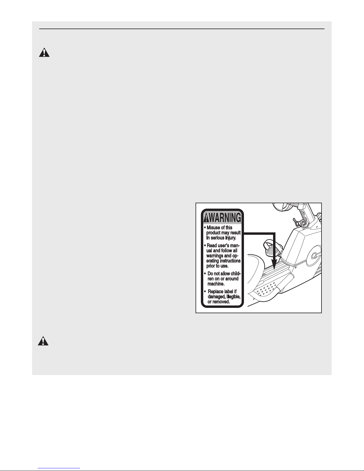
13. The decal shown below has been placed on
the exercise cycle. If the decal is missing, or
if it is not legible, call our Customer Service
Department at 08457 089 009 and order a free
replacement decal. Apply the decal in the
location shown.
7. Keep children under the age of 12 and pets
away from the exercise cycle at all times.
8. Wear appropriate clothing when exercising;
do not wear loose clothing that could
become caught on the exercise cycle. Always
wear athletic shoes for foot protection.
9. The exercise cycle should not be used by
persons weighing more than 115 kg (250
lbs.).
10. The pulse sensor is not a medical device.
Various factors, including the user's move-
WARNING: Before beginning this or any exercise program, consult your physician. This
is especially important for persons over the age of 35 or persons with pre-existing health problems.
Read all instructions before using. ICON assumes no responsibility for personal injury or property
damage sustained by or through the use of this product.
3
BEFORE YOU BEGIN
Congratulations for selecting the new PROFORM
765 TR exercise cycle. Cycling is one of the most
effective exercises for increasing cardiovascular fit-
ess, building endurance, and toning the entire body.
n
The 765 TR exercise cycle offers an impressive array
of features to let you enjoy this healthful exercise in
the convenience and privacy of your home.
For your benefit, read this manual carefully before
you use the exercise cycle. If you have questions
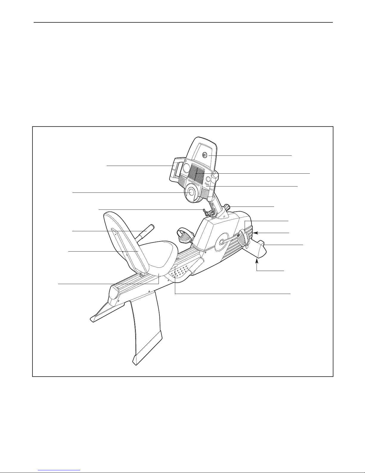
Handgrip Pulse Sensor
CD Player
Water Bottle Holder*
®
after reading this manual, please call our Customer
Service Department at 08457 089 009. To help us
assist you, please note the product model number
nd serial number before calling. The model number
a
is PFEVEX62832. The serial number can be found on
a decal attached to the exercise cycle (see the front
cover of this manual).
Before reading further, please familiarise yourself with
the parts that are labeled in the drawing below.
CD Holder
Fan
Console
Adjustment Knob
Handlebar
Backrest
Seat
REAR
*No bottle is included
Pedal/Strap
Power Jack
Wheel
Leveling Foot
Seat Lever
RIGHT SIDE
4
ASSEMBLY
M8 x 52mm Button
Screw (54)–2
M6 x 16mm Button
Screw (8)–4
M4 x 12mm
Screw (41)–6
M8 Nylon
Locknut (49)–4
M8 Washer
(64)–2
M6 Washer
(66)–4
M8 x 25mm Button
Screw (40)–4
M6 x 22mm Button
Screw (93)–3
M8 x 38mm Button
Bolt (96)–4
M6 x 16mm Tapered
Button Screw (102)–8
M4 x 20mm
Screw (101)–1
M4 x 16mm
Screw (57)–6
M6 x 25mm Button
Screw (99)–1
Assembly requires two persons. Place all parts of the exercise cycle in a cleared area and remove the packing
materials. Do not dispose of the packing materials until assembly is completed.
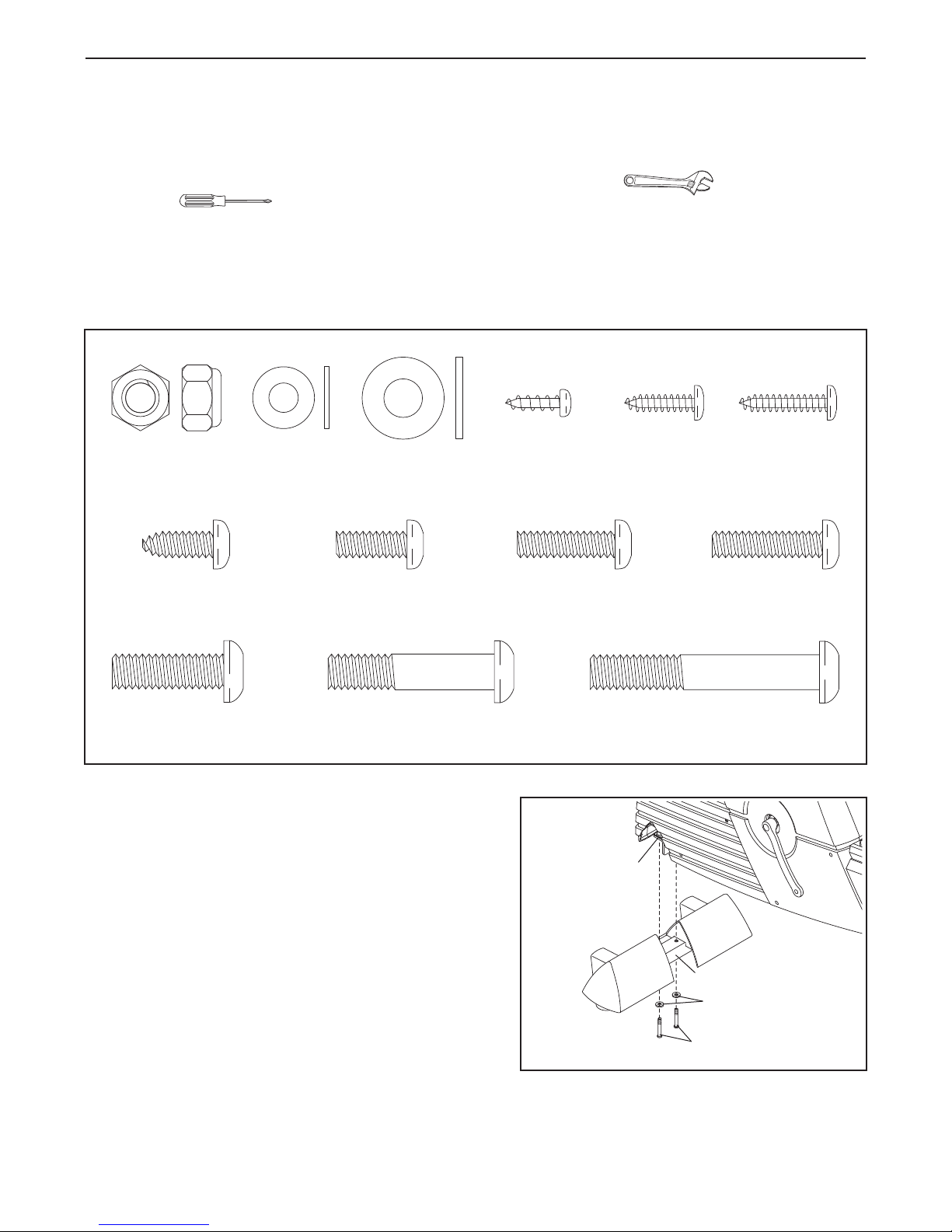
Assembly requires the included tools and your own adjustable spanner and Phillips
screwdriver .
Use the drawings below to identify the small parts used for assembly. The number in parenthesis below each
drawing is the key number of the part, from the PART LIST on pages 28 and 29. The number following the key
number is the quantity needed for assembly. Note: Some small parts may have been pre-assembled. If a part
is not in the parts bag, check to see if it has been pre-assembled.
1. Orient the Front Stabiliser (15) as shown. Whilst another person lifts the front of the Frame (1), attach the
Front Stabiliser to the Frame with two M8 x 52mm
Button Screws (54) and two M8 Washers (64).
5
1
1
15
64
54
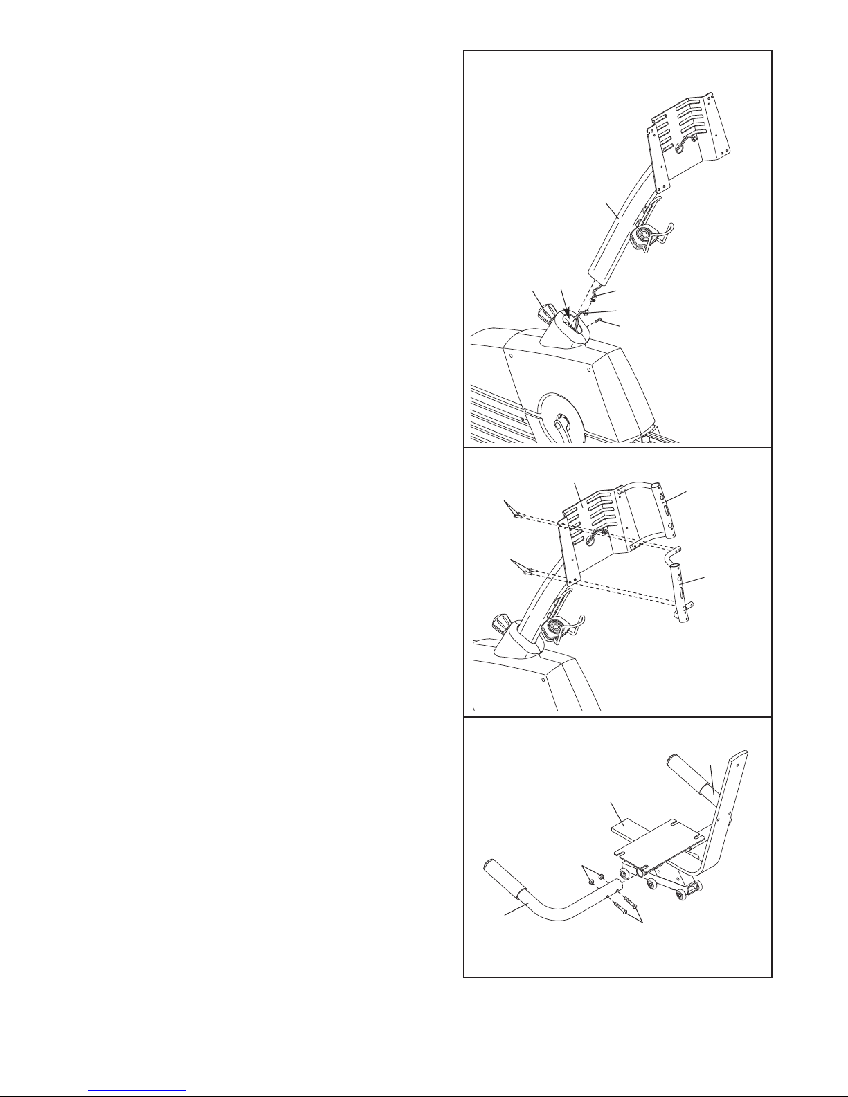
. Whilst another person holds the Upright (2) in the posi-
2
tion shown, connect the Upper Wire Harness (42) to
the Lower Wire Harness (43). Gently pull the upper
end of the Upper Wire Harness to remove any slack
rom the Wire Harnesses.
f
Turn the indicated Adjustment Knob (20) counterclockwise two or three turns to loosen it. Next, pull the Knob,
nsert the Upright (2) into the Frame (1), and then
i
release the Knob. Be careful to avoid pinching the
Wire Harnesses (42, 43). Move the Upright up and
down slightly until the pin on the Knob snaps into
one of the holes in the Upright. Then, turn the Knob
clockwise until it is tight. Tighten the M6 x 25mm
Button Screw (99) into the Frame.
2
ake sure the
M
wire harnesses
do not get
pinched and
damaged during
his step.
t
20
2
1
42
43
99
3. Attach the Left Inner Handlebar (71) to the Upright (2)
with four M6 x 16mm Tapered Button Screws (102).
Attach the Right Inner Handlebar (68) to the
Upright (2) in the same way.
4. Attach a Handlebar (3) to the Seat Bracket (11) with
two M8 x 38mm Button Bolts (96) and two M8 Nylon
Locknuts (49). Make sure that the Nylon Locknuts
are resting in the hexagonal holes in the front of
the Handlebar.
Attach the other Handlebar (3) to the Seat Bracket
(11) in the same way.
3
102
102
4
2
68
71
3
11
49
3
96
6
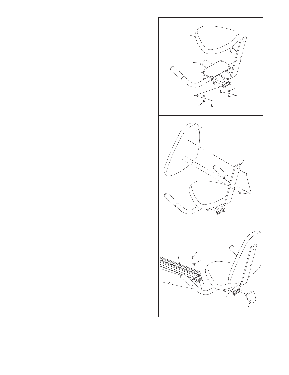
5. Attach the Seat (9) to the Seat Bracket (11) with four
M6 x 16mm Button Screws (8) and four M6 Washers
(66).
5
9
11
66
6. Attach the Backrest (90) to the Seat Bracket (11) with
three M6 x 22mm Button Screws (93).
7. Push down the handle (not shown) on the right side of
the Seat Carriage (10), slide the Seat Carriage into the
Frame Rail (81), and then pull the handle back up.
66
8
6
90
7
8
11
93
Attach a Bumper (82) to the Frame Rail (81) with an
M4 x 20mm Screw (101). Next, press the Frame Rail
Endcap (83) into the end of the Frame Rail.
81
101
82
10
83
7
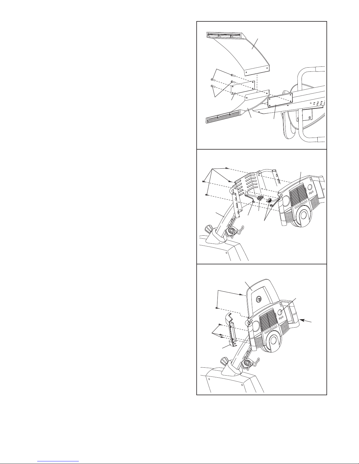
8. With the help of another person, carefully tip the
exercise cycle onto its left side so it is resting on the
Left Inner Handlebar (not shown).
Identify the Left Rear Stabiliser (16), which is marked
ith an “L” sticker. Attach the Left Rear Stabiliser and
w
the Stabiliser Plate (87) to the Frame (1) with two M8
x 25mm Button Screws (40) as shown; do not tighten
the Button Screws yet.
Insert the Right Rear Stabiliser (98) between the
Stabiliser Plate (87) and the Frame (1). Attach the
Right Rear Stabiliser with two M8 x 25mm Button
Screws (40). Tighten all four Button Screws.
8
8
9
40
40
87
16
1
9. See step 10. Remove the three indicated M4 x 12mm
Screws (41) and the Left and Right Handlebar Covers
(6, 5) from the Console (4).
With the help of another person, carefully raise the
exercise cycle so it is resting on the Front and Rear
Stabilisers (not shown).
Whilst another person holds the Console (4) in the
position shown, connect the wire harnesses on the
Console to the Upper Wire Harness (42) and the
Pulse Wire Harness (106). Insert the excess wire harness down into the Upright (2).
Attach the Console (4) to the Upright (2) with four M4
x 12mm Screws (41). Be careful to avoid pinching
the wire harnesses.
10. Attach the CD Holder (104) to the Console (4) with
two M4 x 12mm Screws (41) as shown.
Attach the Left Handlebar Cover (6) to the Console (4)
with three M4 x 16mm Screws (57).
Attach the Right Handlebar Cover (5) to the
Console (4) in the same way.
9
10
57
41
2
41
106
104
4
42
Wire
Harnesses
4
5
6
8
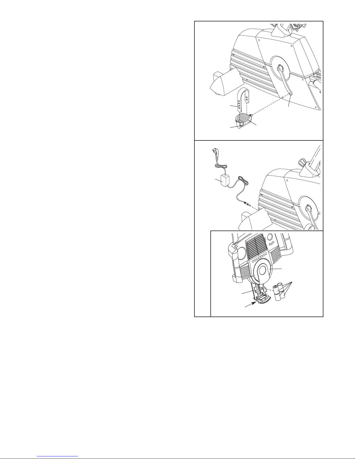
11. Identify the Left Pedal (22), which is marked with an
“L.” Using an adjustable wrench, firmly tighten the
Left Pedal counterclockwise into the Left Crank Arm
24). Tighten the Right Pedal (not shown) clockwise
(
into the Right Crank Arm. Important: Tighten both
edals as firmly as possible. After using the exer-
P
cise cycle for one week, retighten the Pedals. For
best performance, the Pedals must be kept tightened.
Adjust the Left Pedal Strap (25) to the desired position, and press the end of the Pedal Strap onto the tab
on the Left Pedal (22).
Adjust the Right Pedal Strap (not shown) in the
same way.
11
25
Tab
24
22
12. Plug one end of the Power Cord (52) into the jack at
the front of the exercise cycle. Plug the other end of
the Power Cord into an appropriate outlet that is properly installed in accordance with all local codes and
ordinances. Note: In the UK, use the included adapter
(not shown) with the Power Cord.
Note: The console can be operated with batteries
instead of the Power Cord (52) if desired. To install
batteries, follow the instructions below.
See the inset drawing. Press the indicated tab on the
battery drawer and pull the battery drawer down.
Press four “D” batteries into the battery clips; make
sure that the batteries are oriented as shown by
the markings inside of the battery clips. Then,
close the battery drawer. Note: Alkaline batteries are
recommended.
12
52
4
Batteries
Battery
Drawer
Tab
13. Make sure that all parts are properly tightened before you use the exercise cycle. Note: After assembly is
completed, some extra parts may be left over. Place a mat beneath the exercise cycle to protect the floor.
9
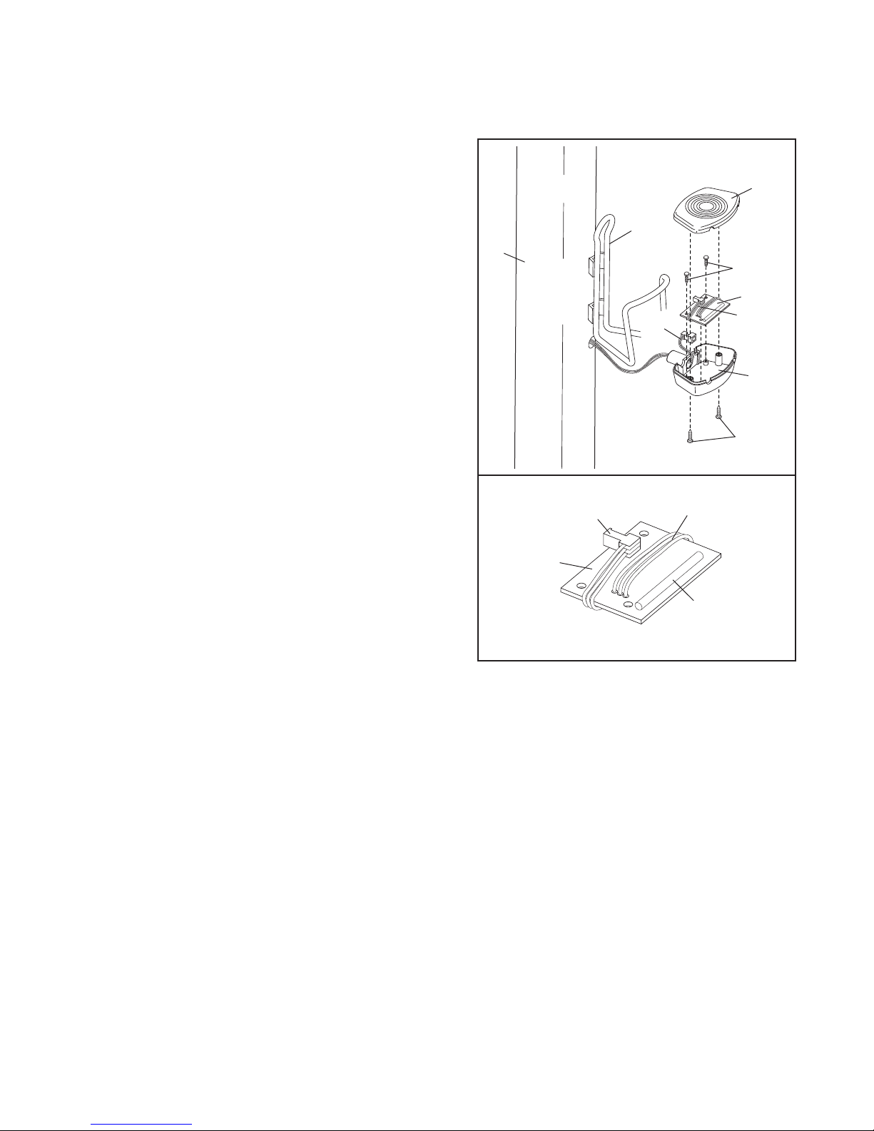
INSTALLING THE RECEIVER FOR THE OPTIONAL CHEST PULSE SENSOR
If you have purchased the optional chest pulse sensor (see page 23), follow the steps below to install
he receiver included with the chest pulse sensor.
t
. Look under the housing (A) and locate the two
1
recessed screws (B). Remove the two screws, and
remove the lid (C) from the housing. Set the lid and
the screws aside.
C
2. Gently remove the housing (A) from the Upright (2)
and the Water Bottle Holder (31).
3. See the bottom drawing. Wrap the wires (D) on the
receiver (E) lengthwise around the receiver as shown.
Make sure that the wires and the connector do not
touch the small cylinder.
4. Hold the receiver (E) so the small cylinder is oriented
as shown, and carefully insert the receiver into the
housing (A). Attach the receiver to the housing with the
two screws (F) included with the chest pulse sensor.
5. Locate the indicated wires (G) inside of the housing
(A). Pull the end of the wires out of the housing and
connect it to the wires (D) on the receiver (E). Make
sure that the connectors snap together.
6. Gently feed the wires into the Upright (2) and insert the
housing (A) into the Upright. Be careful to avoid
pinching the wires.
7. Reattach the lid (C) and the housing (A) to the Water
Bottle Holder (31) with the two screws (B). Note: The
wires included with the chest pulse sensor are not
needed and may be discarded.
2
Connector
E
31
G
F
E
D
A
B
D
Small
Cylinder
10
 Loading...