

Page 1
PL-X900 Series Standard Display
PL-DU6900/PL-DU7900
User Manual
Page 2

Preface
Preface
Thank you for purchasing Digital’ s PL-DU6900/PL-DU7900 Series Standard
Display (hereafter referred to as "the DU").
The DU unit uses the most up-to-date, cost-effective, high-performance architecture and is designed exclusively for use with Digital’ s BOX-Type Industrial
Computers (hereafter referred to as "the PL").
Please read this manual carefully as it explains, step by step, how to use the DU
correctly and safely .
1) It is forbidden to copy the contents of this manual, in whole or in part, except
for the user's personal use, without the express permission of the Digital
Electronics Corporation of Japan.
2) The information provided in this manual is subject to change without notice.
3) This manual has been written with care and attention to detail; however,
should you find any errors or omissions, please contact Digital Electronics and
inform them of your findings.
4) Please be aware that Digital Electronics Corporation shall not be held liable by
the user for any damages, losses, or third party claims arising from the uses of
this product.
All Company/Manufacturer names used in this manual are the registered trademarks of those companies.
© Copyright 2000, Digital Electronics Corporation
PL-DU6900/PL-DU7900 User Manual 1
Page 3
Preface
Essential Safety Precautions
This manual includes procedures that must be followed to operate the DU correctly and safely. Be sure to read this manual and any related materials thoroughly
to understand the correct operation and functions of this unit.
Icon Meaning
Throughout this manual, the following icons are provided next to operations
requiring special attention to allow you to use the DU safely. The operations
described with these icons contain essential safety information. The following is
an example of these icons and their meanings:
Indicates situations where severe bodily
W arning
injury, death or major equipment damage
can occur .
Caution
Indicates situations where slight bodily
injury or machine damage can occur.
WARNINGS
System Design
• Before connecting the DU's power cord terminals to its
terminal block, be sure the power cord is disconnected
from the power supply.
• Do not use power that is beyond the DU's specified voltage range. It may cause a fire or electric shock.
• Before opening the DU unit's cover, to prevent electric
shocks or burns, be sure to disconnect the DU's power
cord from the power supply.
• Do not modify the DU unit. It may cause a fire or an electric shock.
• Do not use touch panel keys or switches for any life related or important disaster prevention situations. Use
separate hardware switches for such keys.
• Do not create touch panel switches that are used to either
control or to ensure the safety of equipment and personnel. Mechanical switches, such as an emergency stop
switch, a deadman (two-handed) start switch, etc., must
be installed and operated via a separate control system.
PL-DU6900/PL-DU7900 User Manual2
Page 4

Preface
• After the PL’s backlight burns out, unlike the PL’s
“Standby Mode”, the touch panel is still active. If the operator fails to notice that the backlight is burned out and
touches the panel, a potentially dangerous machine missoperation can occur.
If your PL's backlight suddenly turns OFF, use the followin g
steps to determine if the backlight is actually burned out.
1) If your PL is
not set to "Standby Mode" and the screen
has gone blank, your backlight is burned out.
2) Or, if your PL
is set to Standby Mode, but touching the
screen does not cause the display to reappear, your
backlight is burned out.
• Do not allow water, liquids, or metal particles to enter
inside the DU's chassis, since they can cause either a
malfunction or an electrical shock. If, however, either of
these events occurs, disconnect the DU unit's power cord
immediately and contact your local DUdistributor .
• Read and understand Chapter 4 “Installation and Wiring”
thoroughly before selecting an installation location for the
DU.
• Do not insert/remove an expansion board or an interface
unit while the DU unit's power cord is connected to the
power supply.
• To prevent a possible explosion, do not install the DU in
areas containing flammable gases.
• The DU is not appropriate for use with aircraft control
devices, aerospace equipment, central trunk data transmission (communication) devices, nuclear power control
devices, or medical life support equipment, due to these
devices’ inherent requirements of extremely high levels of
safety and reliability.
• When using the DU with transportation vehicles (trains,
cars and ships), disaster and crime prevention devices,
various types of safety equipment, non life-support related medical devices, etc. redundant and/or fail-safe
system designs should be used to ensure the sufficient
degree of reliability and safety.
PL-DU6900/PL-DU7900 User Manual 3
Page 5

Preface
CAUTIONS
• When the surface or the frame of the display becomes
dirty, soak a soft cloth in water with a neutral detergent,
wring the cloth tightly, and wipe the display. Do not use
paint thinner, organic solvents, or a strong acid compound to clean the unit.
• Avoid using or storing the DU in direct sunlight, or in excessively dusty, dirty or hot environments.
• Do not use the DU in areas where large, sudden temperature
changes can occur thereby causing condensation to form
inside the unit. This can cause the unit to malfunction.
• Avoid restricting the DU's naturally occuring ventilation, or
storing or using the DU in an environment that is too hot.
• Do not store or use the DU where chemicals and acids
evaporate, or where chemicals and acids are dispersed
into the air.
• Do not hold the DU's display stand to carry the DU. This
stand is not meant for carrying the DU and if it breaks,
the unit may fall and injure you.
LCD Handling Caution
The GP's LCD contains a strong irritant. If the panel is
ever cracked and the LCD's liquid contacts your skin, be
sure to wash it with running water for at least 15 minutes.
If any of this liquid should enter your eye, be sure to flush
your eye with running water for more than 15 minutes and
see a doctor as soon as possible.
PL-DU6900/PL-DU7900 User Manual4
Page 6

Preface
General Safety Precautions
LCD Usage and Handling
• The brightness of the LCD screen will depend on the screen's current display
and the LCD's contrast adjustment. Any brightness variations that result are
normal for LCD displays.
• There are minute grid-points (Dark or Light points) on the LCD surface. These
points are not defects and are a part of the DU panel’s design.
• The displayed color will look different when viewed from an angle outside the
specified view angle. This is also normal.
• When installing this unit, be sure that the screen is viewable from within the
designated direction, otherwise the view angle will be effected.
• Displaying a single screen image for long periods of time can cause an afterimage to remain on the screen. To correct this, turn the unit OFF for 5 to 10
minutes, then ON again. This phenomenon is a common attribute of the LCDs,
and is not a defect. To prevent this effect, you can:
1) Use the Display OFF feature; if the same image is to be displayed for a long
period of time.
2) Change the screen display periodically to prevent the displaying of a single
image for a long period of time.
(For further information about LCD usage and handling, contact your local DU
distributor.)
Prior to Using the DU
After connecting the DU to the PL and setting up the PL's OS, you will need to
input the DU's screen settings and perform touch panel calibration.
BOX-Type Industrial Computer PL-B900/PL-B910 Series Users
Manual.
PL-DU6900/PL-DU7900 User Manual 5
Page 7

Preface
Table of Contents
Preface ............................................................................................................ 1
Essential Safety Precautions ....................................................................... 2
General Safety Precautions ......................................................................... 5
Prior to Using the DU................................................................................... 5
Table of Contents .......................................................................................... 6
PL Model Number ........................................................................................ 8
Documentation Conventions ....................................................................... 8
Special Features ............................................................................................ 9
Package Contents........................................................................................ 10
CE Marking Notes ...................................................................................... 11
UL/c-UL(CSA) Application Notes............................................................ 11...
CHAPTER 1 INTRODUCTION
1.1 System Design......................................................................................1-1
1.1.1 RS-422 and USB Connections ...........................................1-2
1.1.2 Connecting the Dual Displays............................................1-3
1.2 Accessories........................................................................................... 1-5
CHAPTER 2 SPECIFICATIONS
2.1 General Specifications .......................................................................2-1
2.1.1 Electrical.............................................................................. 2-1
2.1.2 Environmental .....................................................................2-1
2.1.3 Structural ............................................................................. 2-2
2.2 Functional Specifications ..................................................................2-3
2.2.1 Performance......................................................................... 2-3
2.2.2 Display .................................................................................2-3
2.3 Names and Functions of DU Parts...................................................2-4
2.4 Display Unit Dimensions ...................................................................2-5
2.4.1 PL-DU6900 External Dimensions ....................................2-5
2.4.2 PL-DU7900 External Dimensions ....................................2-5
2.4.3 PL-DU6900 Installation Fasteners.....................................2-6
2.4.4 PL-DU7900 Installation Fasteners.....................................2-6
PL-DU6900/PL-DU7900 User Manual6
Page 8

CHAPTER 3 OPTIONAL UNITS
3.1 Installation........................................................................................... 3-1
3.1.1 Attaching the Display Expansion Board (PL-PE200) ...... 3-2
3.1.2 Installing the USB Front Access Unit (PL-US200).......... 3-5
CHAPTER 4 INSTALLATION AND WIRING
4.1 DU Installation Cautions................................................................... 4-1
4.1.1 Temperature Related Cautions ........................................... 4-1
4.1.2 Installation Positioning Cautions ....................................... 4-1
4.1.3 Shock / Vibration Related Cautions................................... 4-1
4.2 DU Installation.................................................................................... 4-2
4.2.1 Installation ...........................................................................4-2
4.3 Wiring Cautions..................................................................................4-5
4.3.1 Connecting to PL................................................................. 4-5
Preface
4.3.2 Connecting the Power Cord ...............................................4-5
4.3.3 Connecting the DU’s Power Supply ..................................4-7
4.3.4 Grounding the DU...............................................................4-8
4.3.5 Cautions When Connecting I/O Signal Lines ................... 4-8
CHAPTER 5 MAINTENANCE
5.1 Regular Cleaning................................................................................ 5-1
5.1.1 Cleaning the Display........................................................... 5-1
5.1.2 Installation Gasket Replacement........................................ 5-1
5.2 Changing the Backlight .....................................................................5-2
5.3 Periodic Check Points........................................................................ 5-9
INDEX
PL-DU6900/PL-DU7900 User Manual 7
Page 9
Preface
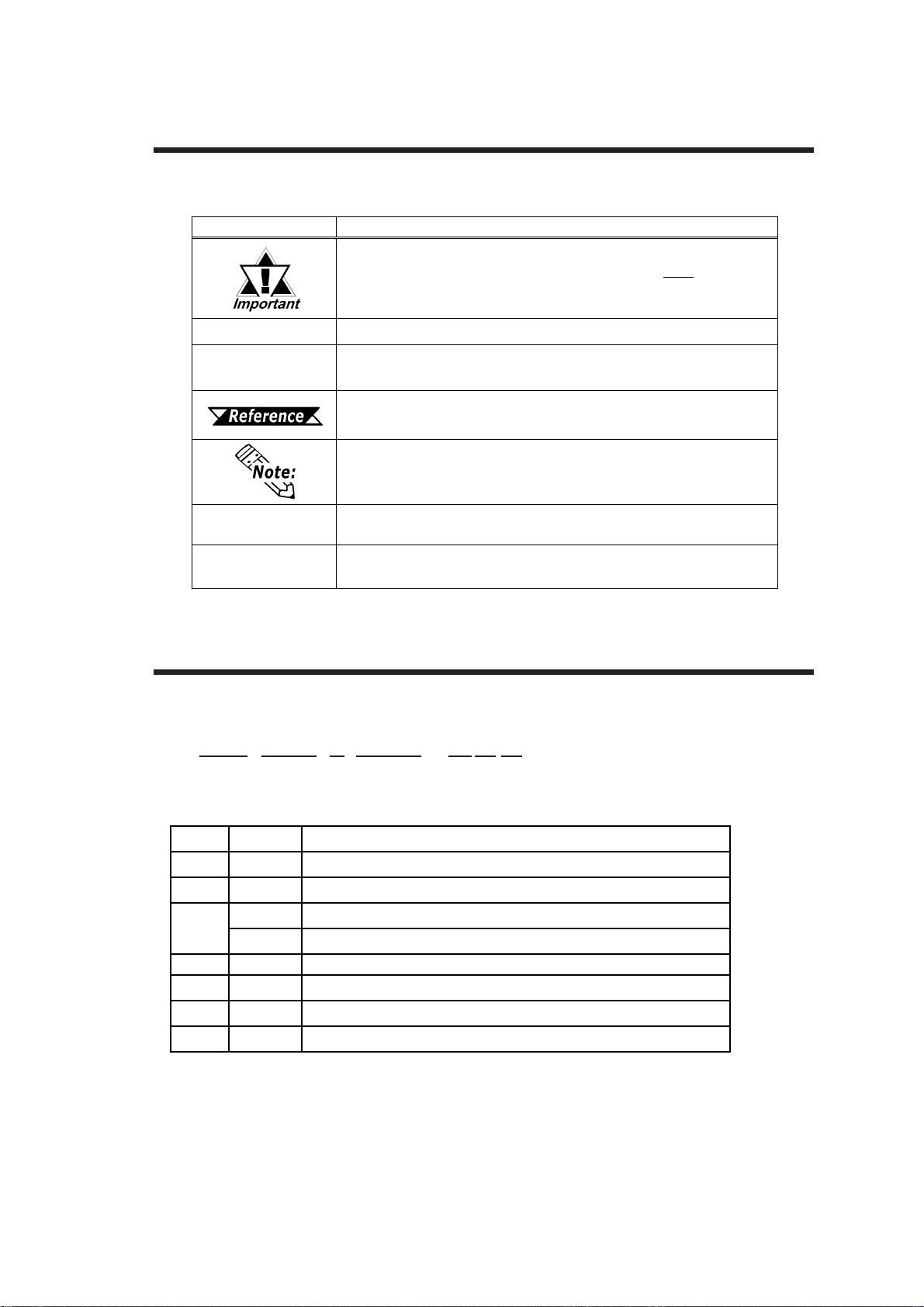
Documentation Conventions
The list below describes the documentation conventions used in this manual.
Symbol
*1
1) , 2)
Indicates important information or procedures that must
for correct and risk-free software/device operation.
Indicates useful or important supplemental information.
Indicates steps in a procedure. Be sure to perform these steps in the
order given.
Refers to useful or important supplemental information.
Meaning
PL
DU
Provides useful or important supplemental information.
Refers to all BOX-Type Industrial Computers (PL-B900 and PL-B910
Series models).
Refers to all standard Displays (PL-DU6900, PL-DU7900).
PL Model Number
be followed
The meaning of the DU model number is explained below.
PL -DU * 900- T42
A B C D E F G
Item Code Meaning
A PL PL S eries Industrial Computer
B DU PL-X900 Series Display Unit
C
D 9 X900 S er ies
E TTFT Color LCD
F 4 CE Marked , UL/c-UL( CS A) Approved
G 2 Revis ion No.
612.1 inch
715 inch
SV GA
XGA
PL-DU6900/PL-DU7900 User Manual8
Page 10
Preface
Special Features
The PL-DU*900’s special features are as follows.
PL-DU6900 - 12.1" High-Brightness Color Display and Wide View Angle
The PL-DU6900’s large 12.1 inch, 800 X 600 pixel TFT LCD display offers
excellent visibility and brightness.
Digital’s top of the line TFT color LCD model allows you to create detailed and powerful visual images, with excellent brightness, a wide viewing angle, and a display
capable of 260,000 colors.
PL-DU7900 - 15.0" High-Brightness Color Display and Wide View Angle
The PL-DU7900’s large 15.0 inch, 1024 X 768 pixel TFT LCD display offers
excellent visibility and brightness.
Digital’s top of the line TFT color LCD model allows you to create detailed and powerful visual images, with excellent brightness, a wide viewing angle, and a display
capable of 260,000 colors.
Installation Options
The PL’s separately designed main unit and display offer you an expanded range
of usage options for all your applications.
Easy Front Panel Installation
The PL is designed to be installed easily into the front of any panel or device. It is
also rugged enough for use in harsh, industrial environments, such as those found
in the factory automation industries and boasts an IP65f rating.
Refer to this chapter’s “What is IP65f?”
High Resolution, Resistive Film Touch Panel
Standard equipment with the PL is a high resolution 1024 X 1024 touch panel. Also, the
mouse emulation utility provides mouse-like functionality and pointer control.
Dual Display Feature (Available for use with PL-B910 Series)
You can connect 2 (two) DUs to a single PL unit using the Display Expansion
Board.
Dual Touch Panel Feature (Available for use with PL-B910 Series)
The DU's Dual Display feature includes a Touch Panel input interlock feature to
prevent accidental operation interruption or mis-operation. This program also
eliminates the need for complicated settings.
USB Interface Feature (Available for use with PL-B910 Series)
The DU is equipped with a USB interface which allows you to connect the DU with any
other USB equipped units (USB I/F Series A).
PL-DU6900/PL-DU7900 User Manual 9
Page 11
Preface
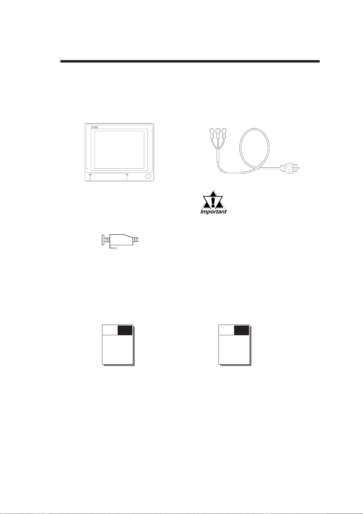
Package Contents
The DU's packing box contains the items listed below. Please check to confirm
that all items shown below have been included.
DU Unit (1)
PL-DU6900-T42
PL-DU7900-T42
Installation Fasteners
(PL-DU6900 8/set)
(PL-DU7900 12/set)
PL-X900 SERIES
ST ANDARD DISPLAY
PL-DU6900/PL-DU7900
USER MANUAL :
English (1)
(This manual)
Power Cord (1)
(for AC100V/AC115V)
This power cord is designed only for AC100V/
AC115V use. Be sure to
use a different cable when
using other than AC100V/
AC115V power.
PL-X900 SERIES
ST ANDARD DISPLAY
PL-DU6900/PL-DU7900
USER MANUAL :
Japanese (1)
PL-X900 *******
USER MANUAL
PL-X900 *****
****************
PL-DU6900/PL-DU7900 User Manual10
Page 12

Preface
UL/c-UL(CSA) Application Notes
The PL-DU*900-T4* is a UL/c-UL(CSA)1950 recognized product. (UL File No.
E171486). Machinery which has a DU installed in it requires UL/c-UL inspection
for the combination of this unit and the machinery .
This unit conforms as a component to the following standards:
UL 1950, Third Edition, dated 1998 March 1st.
(Standard for Safety of Information Technology Equipment, including Electrical
Business Equipment)
CAN/C22.2 No.950-M95
(Standard for Safety of Information Technology Equipment, including Electrical
Business Equipment)
PL-DU6900-T4* (UL Registration Model: 2780053-04)
PL-DU7900-T4* (UL Registration Model: 2780053-03)
• The DU must be used as a built-in component of an end-use product.
• Use the DU indoors only.
• When connecting the DU's power cord, be sure to use a cord that is appropriate
for the current and voltage used (0.75mm2 or larger).
• When installing the DU to a metal panel or cabinet, be sure to design the DU's
power cut-off switch as a separate device that is within easy reach by the unit's
operator.
• There is a danger of explosion if the DU's backup battery is incorrectly replaced.
Replace only with same or equivalent type recommended by the manufacturer .
Dispose of used batteries according to the manufacturer's instructions.
• Be sure the unit the DU is built into uses a UL1950 approved structure.
CE Marking Notes
The PL-DU*900-T4* is a CE marked product that conforms to EMC directives.
This unit conforms as a component to the following standards:
Safety EN60950
EMI <EN50081-2> EN55011, Class A
EMS <EN50082-2> EN61000-4-2, EN61000-4-3, EN61000-4-4,
EN61000-4-6, EN61000-4-8, ENV50204
The DU unit may fail to meet the above standards if the following conditions
are not maintained.
• The DU must be used as a built-in component of an end-use product.
• Use the DU indoors only.
PL-DU6900/PL-DU7900 User Manual 11
Page 13

Preface
• When connecting the DU's power cord, be sure to use a cord that is appropriate
for the current and voltage used (0.75mm2 or larger).
• When installing the DU to a metal panel or cabinet, be sure to design the DU's
power cut-off switch as a separate device that is within easy reach by the unit's
operator.
• There is a danger of explosion if the DU's backup battery is incorrectly replaced.
Replace only with same or equivalent type recommended by the manufacturer .
Dispose of used batteries according to the manufacturer's instructions.
• Be sure the unit the DU is built into uses an EN60950 approved structure.
PL-DU6900/PL-DU7900 User Manual12
Page 14

Chapter
1 Introduction
1.1 System Design
1. System Design
2. Accessories
USB Front
Access Unit
(PL-US200)
<DU>
Display Expa nsion Board
(PL-PE200)
TFT Color LCD Touch Panel
<PL>
Screen
Protection Sheet
(PL-CS100)
Display Unit's Reset
Button
Connection Cable
(PL-CB200-10M)
(PL-CB200-5M)*1
PL-B900/PL-B910 Series Unit
Cable Connection
Attached to DU Unit
BOX-Type Industrial Computer (PL)
*1 When connecting the Touch Panel using aUSB cable, be sure to use the PL-CB200-5M.
Optional Unit
Included in
Standard Unit
The above System Configuration indicates only the connection between
DU unit and the PL. The actual positioning of these units will differ.
1-1PL-DU6900/PL-DU7900 User Manual
Page 15
Chapter 1 - Introduction
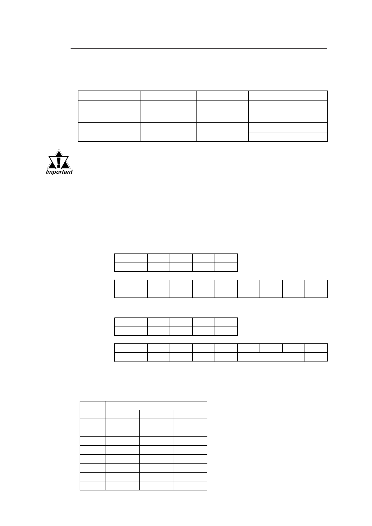
1.1.1 RS-422 and USB Connections
You canconnect a touch panel using either a RS-422 or a USB cable.
The RS-422 and USB cables have limitations concerning the PL type, OS type and
number of DU units.
Touch Panl e Cable PL Type OS Type Displ a y Connection Type
RS- 422 Cab le
USB Cab le
PL-B 900 Series,
PL-B 910 Series
PL-B 910 Series
Windows® 95,
Window s NT
Windows
Second Edition
®
®
98
Sing le D is pla y
4.0
Sing le D is pla y
Dual Display
• When a DU is connectied via a USB cable, be sure to wait 3 seconds
after turning the power OFF before turning it ON again.
• Be sure to use only the OS types shown here with each cable. If a
different type OS is used, the utility software (drivers, etc.) is not
supported.
Dip Switch Settings
Depending on the touch panel cable used, the DU unit's rear face dip switch settings
will change. These settings must also be set on the PL unit's side face dip switches.
RS-422 Cable Settings
PL SetingsSW No.1234
On or OFF ON OFF ON OFF
DU SettingsSW No.12345678
On or OFF ON OFF ON OFF OFF OFF OFF ON
USB Cable Settings
PL SetingsSW No.1234
On or OFF ON OFF ON OFF
DU SettingsSW No.12345678
On or OFF OFF ON OFF ON OFF
St at ion Number
For Station Number settings, Dip SW No.s 0 to 7 can be used. The combination of
Dip SW No.s 5 to 7 determines the Station Number. The following list shows dip
switch combinations and each combination’s allocated station number.
Station
Number
0ONONON
1 OFF ON ON
2ONOFFON
3OFFOFFON
4ONONOFF
5 OFF ON OFF
6ONOFFOFF
7 OFF OFF OFF
567
SW No.
1-2 PL-DU6900/PL-DU7900 User Manual
Page 16
Chapter 1 - Introduction
1.1.2 Connecting the Dual Displays
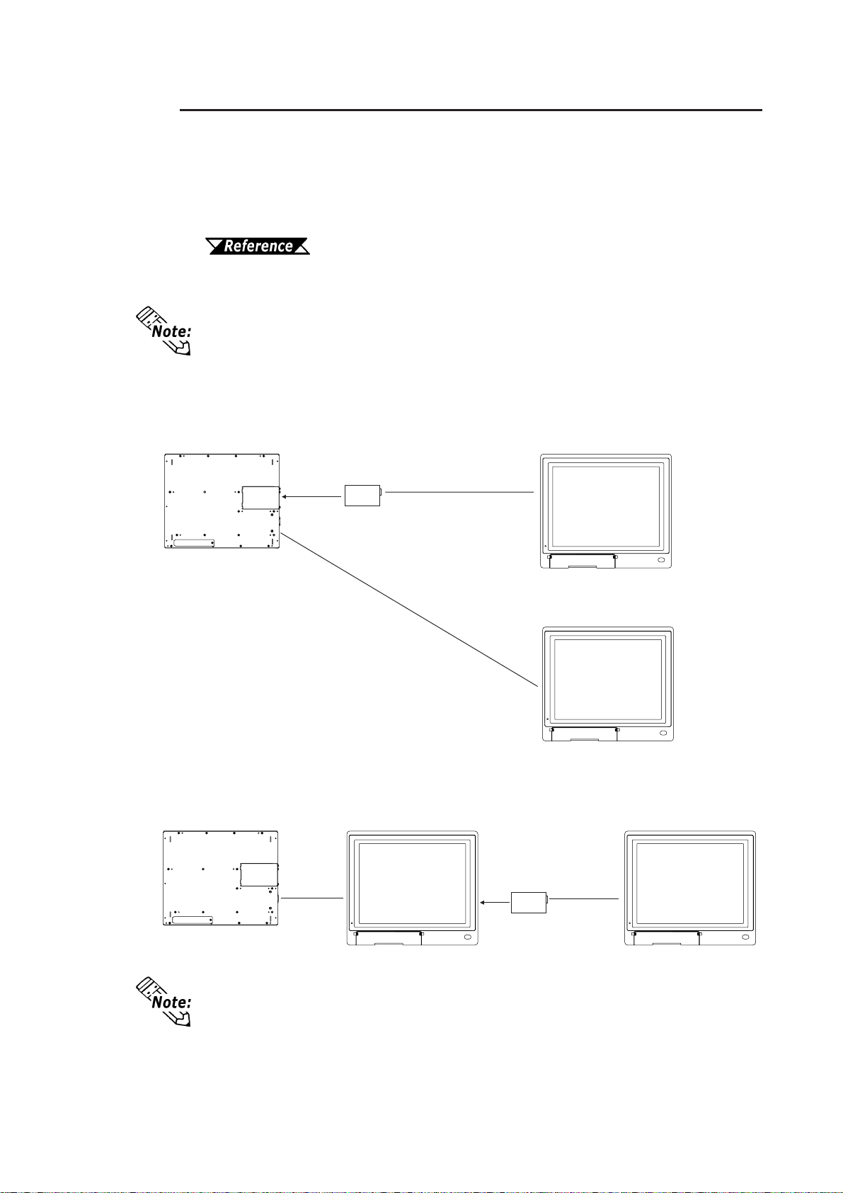
When a USB cable is used, up to 2 DU units can be connected to a single PL unit.
Connecting two displays requires two of the optional display cables (PL-CB200-
5M) and one Display Expansion Board (PL-PE200). Use the following explanations when connecting the DUs and the Display Expansion Board.
Chapter 3.1.1 Attaching the Display Expansion Board (PL-PE200)
When connecting an RS-422 Cable, only one display can be attached to one
PL unit.
There are two types of installation methods to use; the Star Method or the Daisy
Chain Method.
Star Method
With the Star Method, the Display Expansion Board is installed in the PL and
both display cables are connected to the PL.
Display Expansion
Board
(PL-PE200)
PL-B910 Series Unit
DU
Daisy Chain Method
DU
With this method, the Display Expansion Unit is installed in the first DU unit, and
the 2nd DU unit is connected to the first DU unit.
PL-B910 Series Unit
The above explanations show the patterns of the PL and DU units connections. They
will differ from physical PL and DU units placements.
PL-DU6900/PL-DU7900 User Manual
DU1
Display Expansion
Board
(PL-PE200)
DU2
1-3
Page 17
Chapter 1 - Introduction
When attaching the Dual Displays, be sure of the following points.
- The PL unit is a PL-B910 series unit (PL-B910 or PL-B911).
- The Touch Panel connection cable should be a USB cable.
- The operating system is Windows 98 Second Edition.
- Set the PL and DU's dip switch to the USB Cable Settongs. For information
about PL and DU unit dip switch settings,
1.1.1 RS-422 and USB Connections
- The DU units used are the same model. (A PL-DU6900-T42 cannot be used with
a PL-DU7900-T42 unit.).
- Be sure each DU unit’s station number is unique.
1.1.1 RS-422 and USB Connections
- Be sure cable used to connect the displays the PL-CB200-5M.
• Do not connect more than 2 DU units to a single PL, since doing so
may cause a malfunction.
• When using Dual Displays, be sure to install the PL's interlock program to prevent interlock feature conflicts and PL unit malfunctions.
BOX-Type Industrial Computer PL-B900/PL-B910 Series
Users Manual.
Dip Switch Settings
Dip Switch Settings
1-4 PL-DU6900/PL-DU7900 User Manual
Page 18
Chapter 1 - Introduction
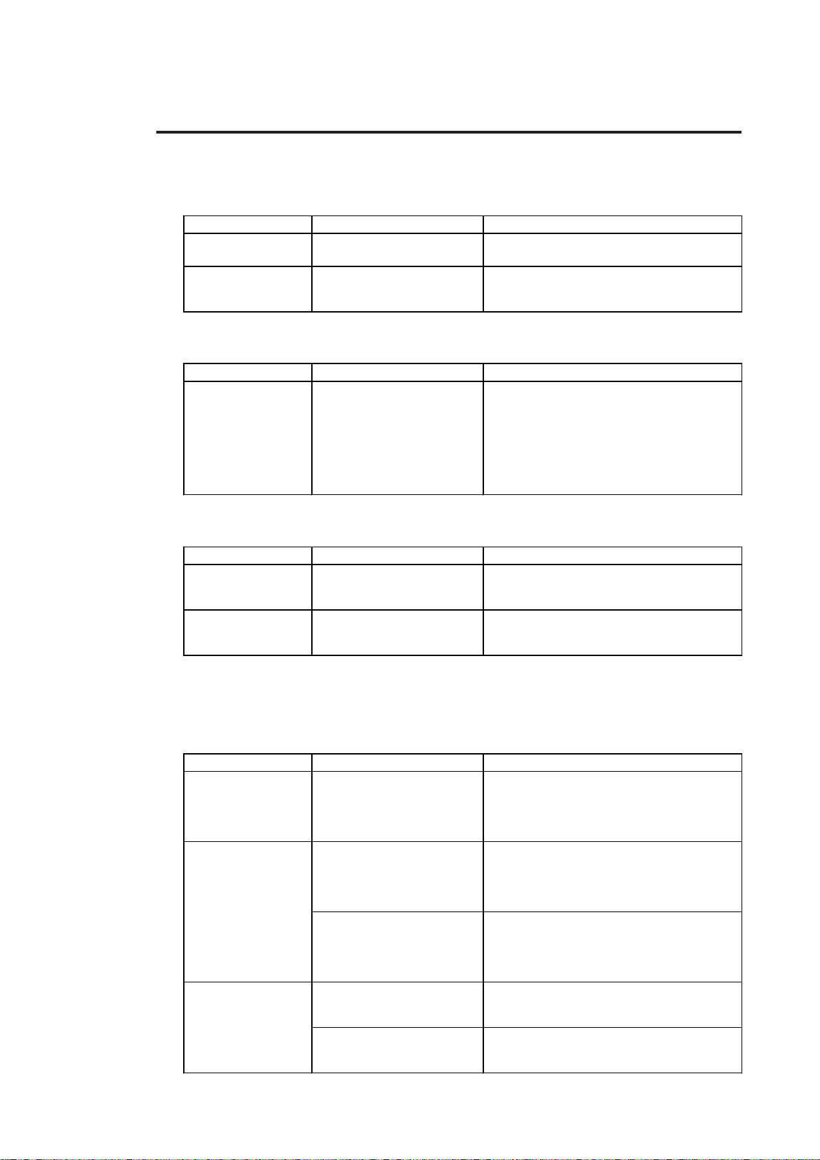
1.2 Accessories
All accessories listed below are produced by the Digital Electronics Corporation.
Attachment Units
Product Nam e Model No. Description
Displ a y Expa nsion
Board
USB Front Access
Unit
Screen Protection Items
Product Nam e Model No. Description
Screen Protection
Sheet
PL-P E 200 Allows y ou to connect 2 DUs t o a PL.
PL-US 200 Allows y ou t o connect other US B equipped
units to the DU from the front of the DU.
PL-CS 100 Disposable pr ot ective and dirt-r es ist ant sheet
for t he DU's screen. The DU's t ouch panel
can be used with this cover sheet attached.
(5/set)
<Both for P L- DU6900 and P L- DU7 900>
Display Cables
Product Nam e Model No. Description
Displ a y Expa nsion
Board
USB Front Access
Unit
Maintenance Items
PL-CB200-5M
PL-CB200-10M
Connects S t an dard Display and Main Unit.
(5m)
Connects S t an dard Display and Main Unit.
(10m) (Us ed only with R S -422 connection)
These optional items were originally included in either the DU itself or in its
packing box. These items are sold separately as optional maintenance items.
Product Nam e Model No. Description
Installation
Fastener
Installation Gasket
Replacement
Backlight
GP070-AT00-MS Fasteners to attach the D U to a panel. Same
as t he fastener included in th e DU' s or iginal
equipment package.
PL-WS100 Provides a drip r es is tant seal when ins t alling
the DU. Same as the DU's original seal. < For
PL-DU6900>
PL-WS300 Provides a drip r es is tant seal when ins t alling
the DU. Same as the DU's original seal. < For
PL-DU7900>
GP675-B L00- MS Spare B acklight for maintenance.
(2 bulbs/set) < For P L- DU 6900>
PL7900-B L0 0- MS Spare B acklight for maintenance.
(2 bulbs/set) < For P L- DU 7900>
PL-DU6900/PL-DU7900 User Manual
1-5
Page 19

Chapter 1 - Introduction
Commercially Available Items
The PL-B910 Series units can use USB compatible devices. However, among the
commercially available USB devices, not all will be compatible with the PL unit.
For a list of the USB units that can be used with your PL, please contact your local
PL distributor .
When using USB type devices, be sure they are USB compatible, and be sure to read
that device's installation guide prior to connecting it to the PL.
When a USB high speed device (12Mbps) is used, an error will occur,
and certain PL peripheral units will not operate correctly. (ex. MO drive
units, PC card units, FD drive units, and others)
1-6 PL-DU6900/PL-DU7900 User Manual
Page 20
1. General Specifications
Chapter
2. Functional Specifications
3. Names and Functions of DU Parts
2 Specifications
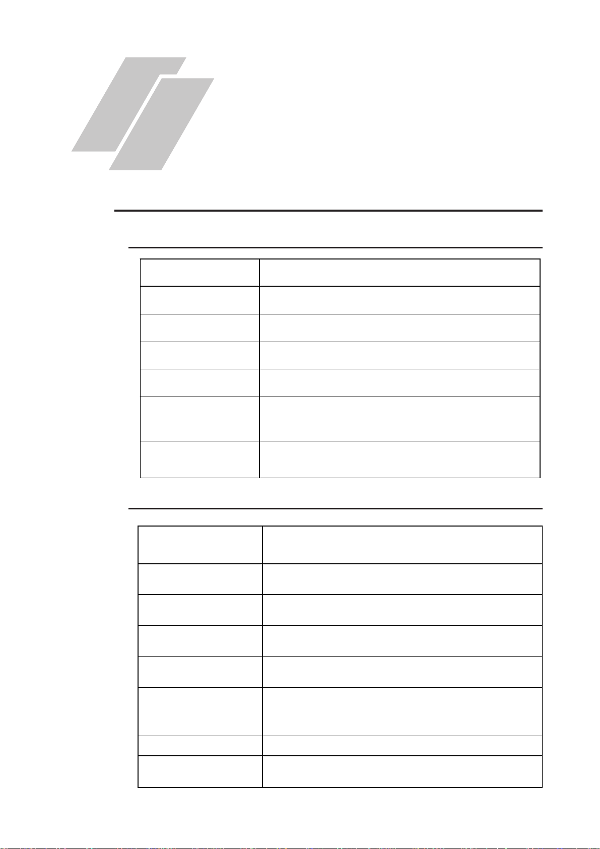
2.1 General Specifications
2.1.1 Electrical
4. Display Unit Dimensions
Input Voltage
Rated Voltage
Rated Frequency
Allowable Voltage Drop
Power Consumption
Voltage Endurance
Insulation Resistance
2.1.2 Environmental
Ambient Operating
Temperature
AC100V to AC240V
AC85V to AC265V
50Hz or 60Hz
1 cycle or less
(Actual drop can be more than 1 second)
50VA or less
AC1500V, 20mA for 1 minute
(between charging and FG terminals)
10MΩ or higher at DC500V
(between charging and FG terminals)
o
0
C to +50oC
o
C to +60oC
Storage Temperature
Ambie nt Humidi ty
Atmosphere
Vibration Resistance
30%RH t o 85 %RH (wit h n o condensat ion)
Free of conductiv e dus t a nd corros ive gasses
2
19.6m/s
(10Hz to 25Hz in X, Y, Z directions for 30min.)
-10
Noise Voltage: 1500Vp-p
Noise Endurance
(via noise simulator)
Pulse Dur at ion: 50 ns, 500ns, 1µs
Arise Time: 1ns
Noise Immunity
Electrostatic Di scha r g e
Immunity
2kV (complies wit h I E C 61000-4- 4)
4kV (complies wit h I E C 61000-4- 2)
PL-DU6900/PL-DU7900 User Manual 2-1
Page 21
Chapter 2 - Specifications
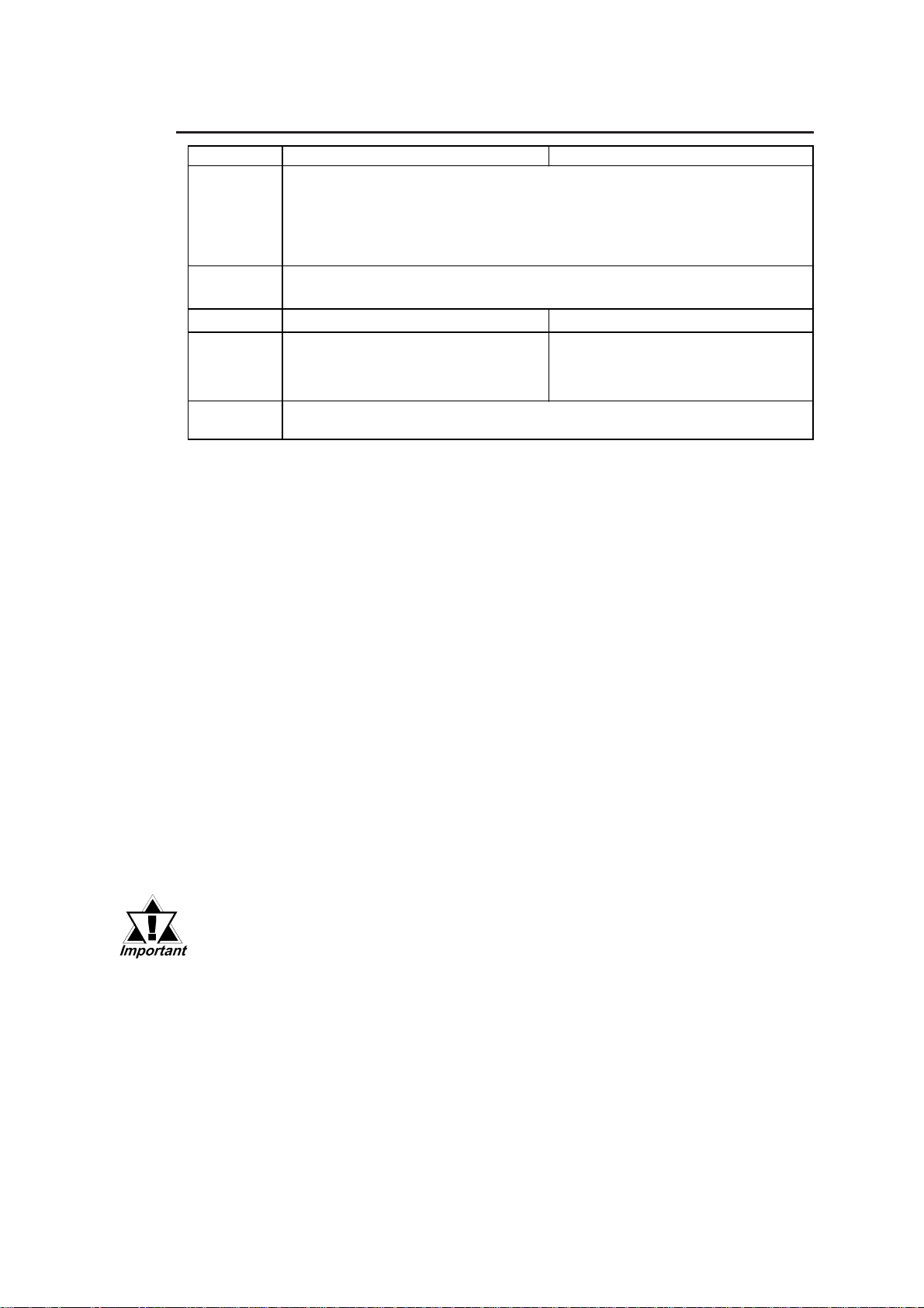
2.1.3 Structural
Ratings
Cooling
Method
Weight
5.5 K g ( 12.1lb) or less 7.0 K g ( 15.4lb) or less
PL-DU6900 PL-DU7900
Equivalent t o IP65f *1(JEM1030)
(fr on t face only - when inst alled in pane l)
Unit Composit ion: Single Unit Type
Installation Method: In a solid panel
Natural air circulation
External
Dime nsions
Grounding
346mm (13.62in.) <W> x 287mm (11. 3in.) <H>
x 63mm (2.48in.) <D>
(main unit only)
100Ω or less gr ounding res is tance
374mm (14.72in.) <W> x 325mm (12. 8in.) <H>
x 74mm (2.91in.) <D>
(main unit only)
*2
*1 The front face of the DU unit, installed in a solid panel, has been tested using conditions
equivalent to the standards shown in the specification . Even though the DU unit’s level of
resistance is equivalent to these standards, oils that should have no effect on the DU can
possibly harm the unit. This can occur in areas where either vaporized oils are present, or
where low viscosity cutting oils are allowed to adhere to the unit for long periods of time. If
the DU’s front face protection sheet becomes peeled off, these conditions can lead to the
ingress of oil into the DU and separate protection measures are suggested. Also, if nonapproved oils are present, it may cause deformation or corrosion of the front panel’s plastic
cover. Therefore, prior to installing the DU be sure to confirm the type of conditions that
will be present in the DU’s operating environment.
If the installation gasket is used for a long period of time, or if the unit and its gasket are r emoved from the panel, the original level of the pr otection cannot be guaranteed. To maintain the
original protection level, you need to r eplace the installation gasket regularly.
*2 Be sure to use your country's applicable standard.
2-2
When using the DU with an optional unit, be sure to also confirm the
option unit’s specifications.
PL-DU6900/PL-DU7900 User Manual
Page 22
Chapter 2 - Specifications
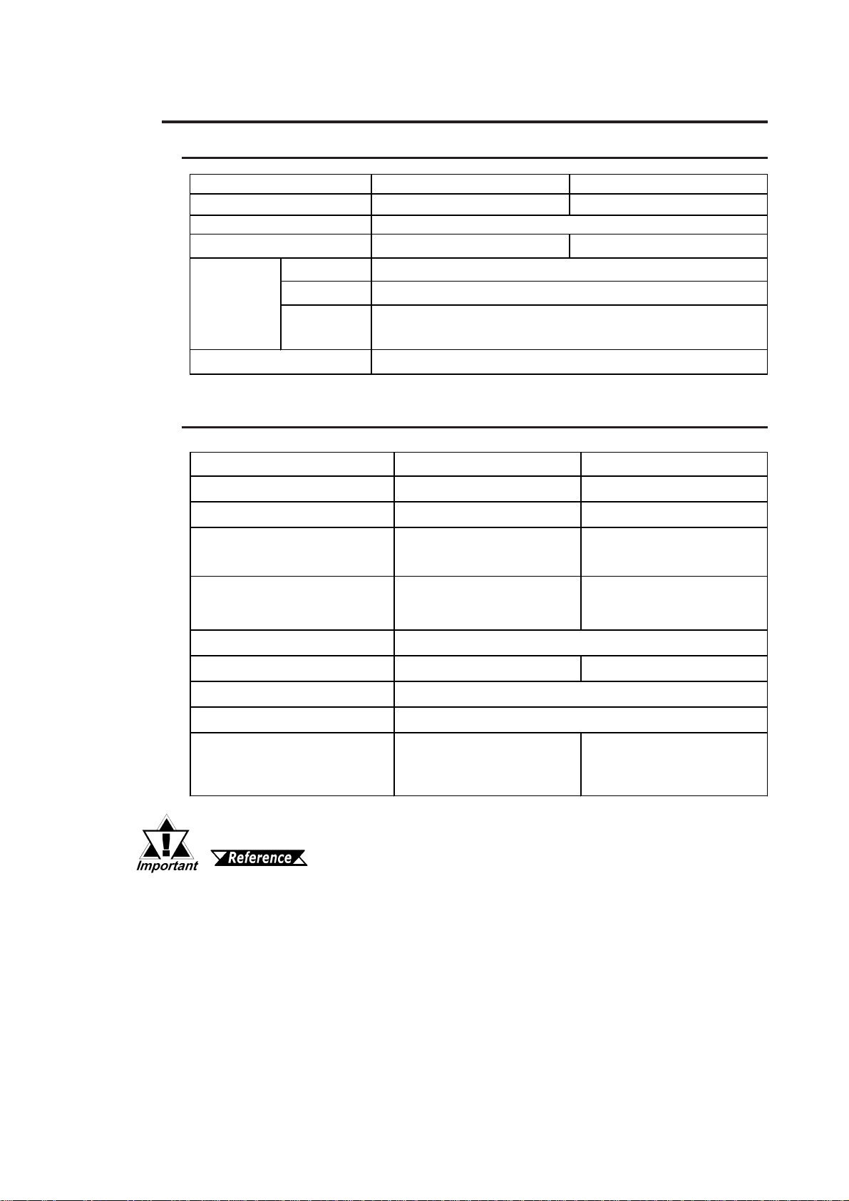
2.2 Functional Specifications
2.2.1 Performance
PL-DU6900 PL-DU7900
Graphics
VESA
Display Unit
Touch Panel
I/F
Resolution
Interface
USB I/F
2.2.2 Display
Type
SVGA ( 800 X 600 dot s) XGA (1024 X 768 dots)
16 colors/ 256 colors/ 32k colors/ 64k colors
12.1 inch TFT SVGA 15.0 inch TFT XGA
Resisive Film (Ana log )
1024 X 1024
COM4 (Uses Mouse E mulator )
USB I n t er f a ce (USB cable uses the USB int er f ace)
1ch (Only when using US B cable)
PL-DU6900 PL-DU7900
Type
Density
Dot Pi t ch
Nom inal Di spl ay Area
Colors
Brig h tn ess Co n tro l
Contra st Control
Backlight
Backlig h t Life ti me
(time r eq ui r ed for br i gh tness to fall to hal f its
normal level)
TFT Color LCD (12.1 inch) TFT Color LCD (15 inch)
800 X 600 pixels 1024 X 768 pixels
0.3075mm X 0.3075 mm
(0.01in. X 0.01in.)
246.0mm X 184.5 mm
(9.69in. X 7.26in.)
0.297mm X 0.297mm
(0.01in. X 0.01in.)
304.1mm X 228.1mm
(11.97in. X 8. 98in. )
260,000
Not Available Available
Not Available
CCFL (Replaceable)
25,000 hours at an ambient
temperatur e of 25
o
C
50,000 hours at an ambient
temperatur e of 25oC
When replacing the Backlight, contact your local distributor.
5.2 Changing the Backlight
PL-DU6900/PL-DU7900 User Manual 2-3
Page 23

Chapter 2 - Specifications
2.3 Names and Functions of DU Parts
A,B
C
D
<Inside the Front Maintenance Cover>
FG
PL-DU6900
<Inside the Front Maintenance Cover>
FGH
PL-DU7900
I
J
K
L
PL-DU6900 Rear View
PL-DU6900 Side View
K
LM
PL-DU6900 Bottom View
E
M
I
J
N
A: Display Area
Display output area.
B:Touch Panel
A high resolution analog type touch panel.
Allows you to create your control systems
without using a key board.
C:Status LED
The status of the lamp changes according to
the alarm type detected by the RAS feature.
BOX-Type Industrial Computer PL-B900/B910 Series Users Manual
D: Front Maintenance Cover
Open this cover when using the Hardware
Reset Switch.
E: IrDA
This feature is currently unavailable.
F: (This feature is unavailable with DU)
G: Hardware Reset Switch
Resets the Display Unit only.
H: Brightness Adjustment Slide
Allows adjustment of backlight brightness.
(Can be used for PL-DU7900 only.)
I: Power Switch
Turns ON/OFF the DU’s power supply.
J : Power Terminals
The DU’s AC100V/240V power cord termi-
nals are connected here.
K: USB Connector
USB I/F, (USB 1.0 compatible.) Any other
USB connection compatible units can be
connected here.
L: PL Connector
The communication interface for PL-B900/PLB910. To use this connector, the optional unit
PL-CB200-10M is required.
M: Dip Switch
Used for setting the T ouch Panel Communication
method (RS-422/USB) and station (ID) numbers.
1.1.1 RS-422 and USB
Connections
Dip Switch Settings
N: Display Stand
Used to support the DU when it is removed
from its installation panel.
2-4
PL-DU6900/PL-DU7900 User Manual
Page 24
Chapter 2 - Specifications
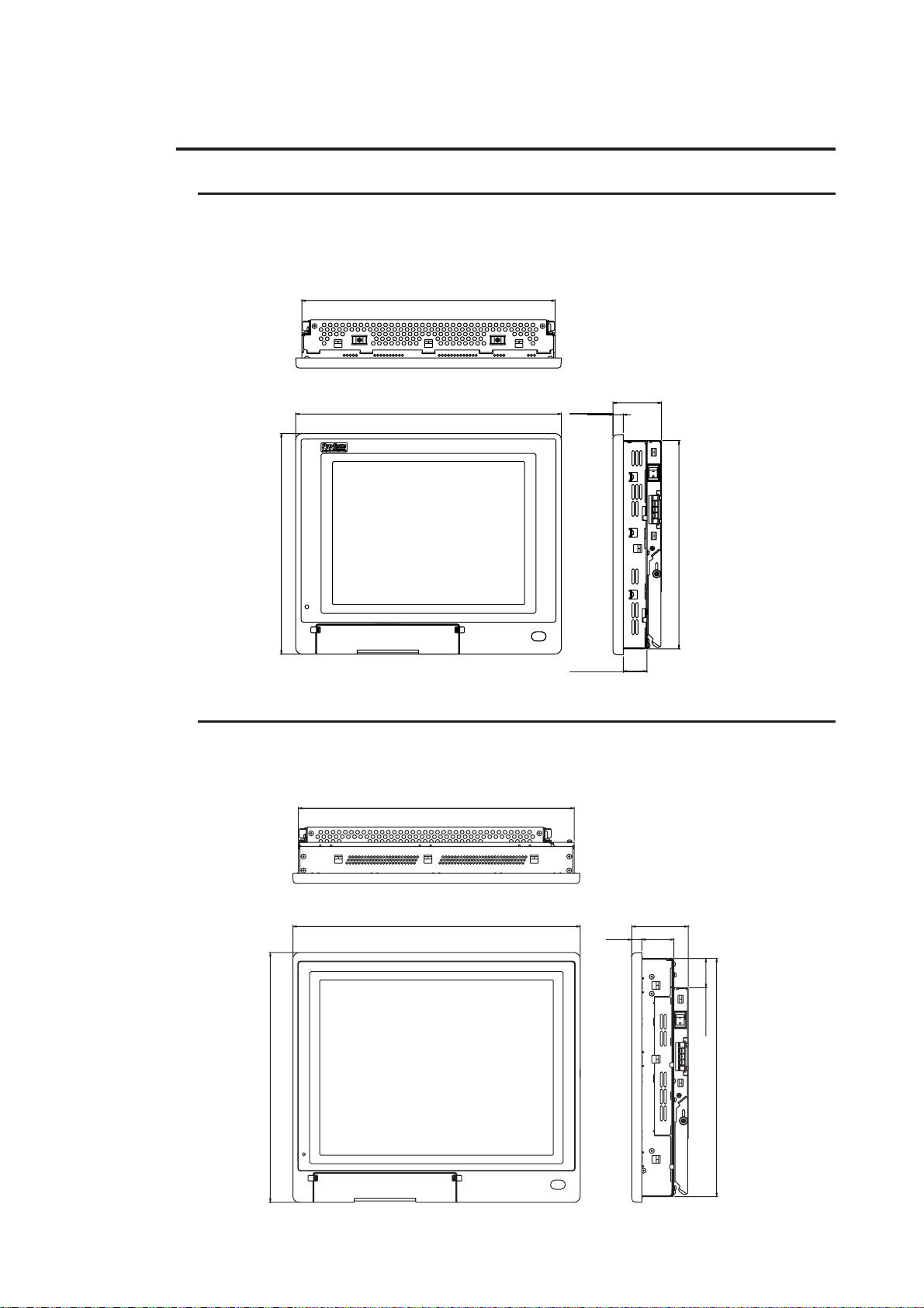
2.4 Display Unit Dimensions
2.4.1 PL-DU6900 External Dimensions
Unit: mm <in.> (Main Unit Only)
Top View
330 <12.99>
Side View
Front View
346 <13.62>
14 <0.55>
63 <2.48>
287 <11.30>
31 <1.22>
2.4.2 PL-DU7900 External Dimensions
Unit: mm <in.> (Main Unit Only)
Top View
359 <14.13>
Front View
374 <14.72>
14<0.55>
271 <10.67>
Side View
74 <2.91>
41 <1.61>
(38 <1.50>)
325<12.8>325<12.8>
325<12.8>325<12.8>
325<12.8>
310 <12.20>
PL-DU6900/PL-DU7900 User Manual 2-5
Page 25
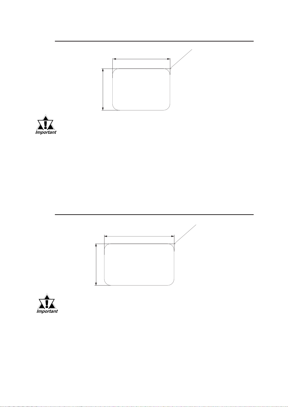
2.4.3 PL-DU6900 Installation Fasteners
Unit: mm <in.>
+0.5
331 <13.03 >
0
0
+0.02
+0.5
0
272 <10.71 >
• Be sure the thickness of the panel is from 1.6mm (0.06in.) to
10mm (0.39 in.)
• Depending on material used for panel surface, you may need to
strengthen the panel surface. Especially, if high levels of vibration
are expected and the DU’s installation surface (i.e. an operation
panel’s door, etc.) can move (i.e. open or close) due consideration
should be given to the DU’s weight.
• To insure that the DU’s water resistance is maintained, be sure to
install the DU into a panel that is flat and free of scratches or dents.
+0.02
0
4-R2 or less
• Be sure all installation tolerances are maintained to prevent the unit from
falling out of its installation panel, or allowing water to enter inside.
2.4.4 PL-DU7900 Installation Fasteners
Unit: mm <in.>
+0.5
360 <14.17 >
0
0
+0.02
+0.5
0
311 12.24 >
• Be sure the thickness of the panel is from 1.6mm (0.06in.) to
10mm (0.39 in.)
• Depending on material used for panel surface, you may need to
strengthen the panel surface. Especially, if high levels of vibrtion
are expected and the DU’s installation surface (i.e. an operation
panel’s door, etc.) can move (i.e. open or close) due consideration
should be given to the DU’s weight.
+0.02
0
4-R2 or less
• To insure that the DU’s water resistance is maintained, be sure to
install the DU into a panel that is flat and free of scratches or dents.
• Be sure all installation tolerances are maintained to prevent the unit from
falling out of its installation panel, or allowing water to enter inside.
Page 26
Chapter
3 Optional Units
3.1 Installation
The following explanation pages describe the installation procedures for the Display
Expansion Board (PL-PE200) and the USB Front Access Unit (PL-US200).
For information about the installation of other option units, please refer to those
unit’s individual [Operation Instructions].
1. Installation
WARNINGS
To avoid electric hazards, be sure to turn the PL’s power OFF
before installing any optional units or expansion boards.
• Use a screwdriver to loosen or tighten the screws. Be careful not to
over-tighten any screws, since it may damage the equipment.
• Be careful when removing or inserting any screws that they do not
fall inside the body of the DU.
3-1PL-DU6900/PL-DU7900 User Manual
Page 27
Chapter 3 - Optional Units
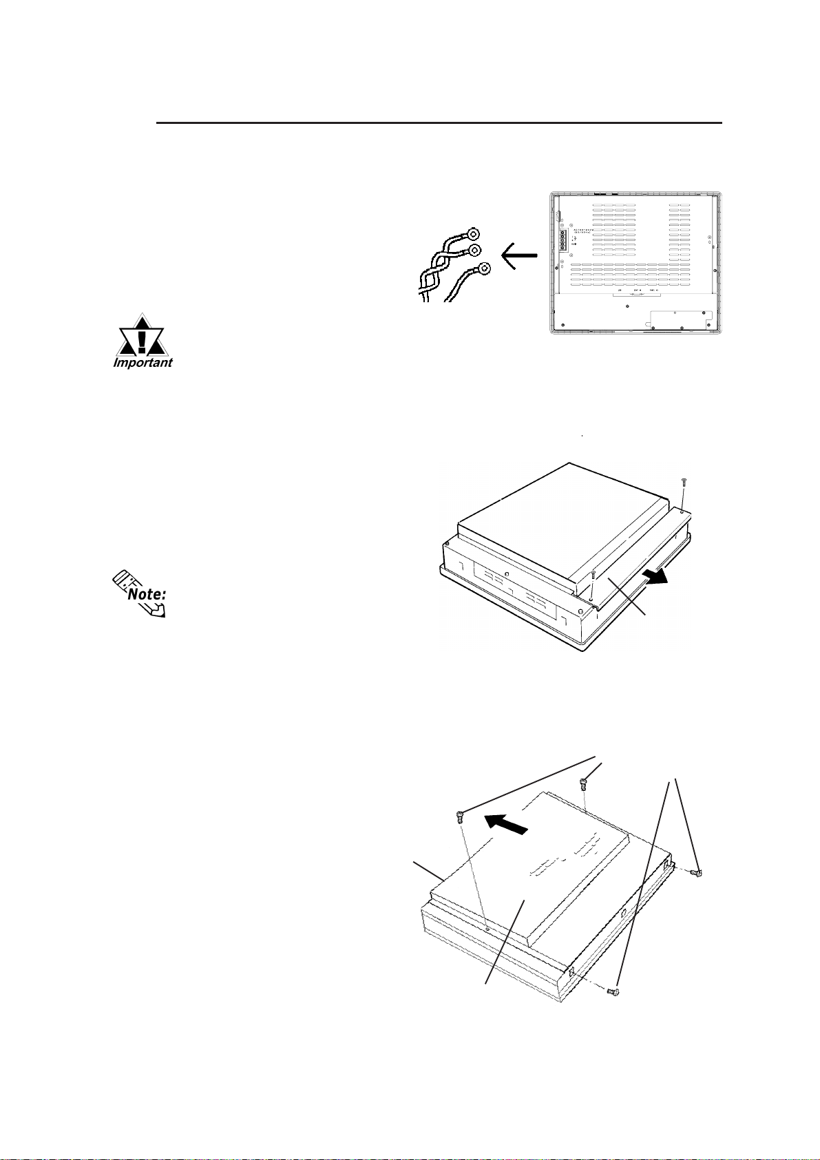
3.1.1 Attaching the Display Expansion Board (PL-PE200)
In this explanation, drawings for the PL-DU7900-T42 drawings are used.
1) Disconnect the DU
power cord terminals
from the DU's power
terminal block.
Be sure to place the
DU unit on a flat, lever
surface prior to installing the PL-PE200. This
will prevent damage to
the DU and the accidental cutting of any of
its power cord terminals.
The PL-DU7900-T42 is
equipped with a Side Cover.
When installing the PLPE200 in a PL-DU7900-T42,
you need to unscrew this
cover's two (2) attachment
screws and remove the cover.
Remove
Power T erminals
DU
Side Cover
Attachment Screws
2) Unscrew the DU’s four
(4) attachment screws
and slide the Rear Part
upwards.
3-2 PL-DU6900/PL-DU7900 User Manual
T op Face
Rear Cover
Page 28
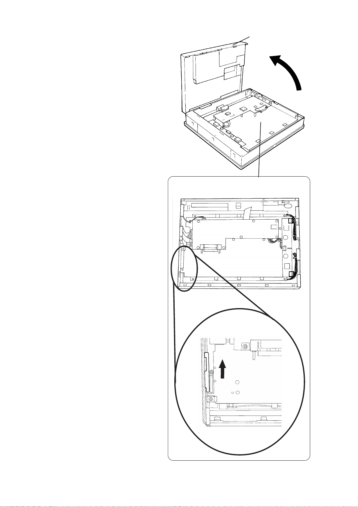
3) Remove the Rear
Cover and expose the
interior of the DU
Front Panel (see Fig.
A.)
4) Loosen the Side
Cover’s screw, and
push the Front Panel’s
Slide in the direction
shown to release it.
(See Fig. B.) Then,
tighten the Side
Cover’s screw.
Chapter 3 - Optional Units
Rear CoverFig. A
Fig. B
PL-DU6900/PL-DU7900 User Manual
Slide
3-3
Page 29
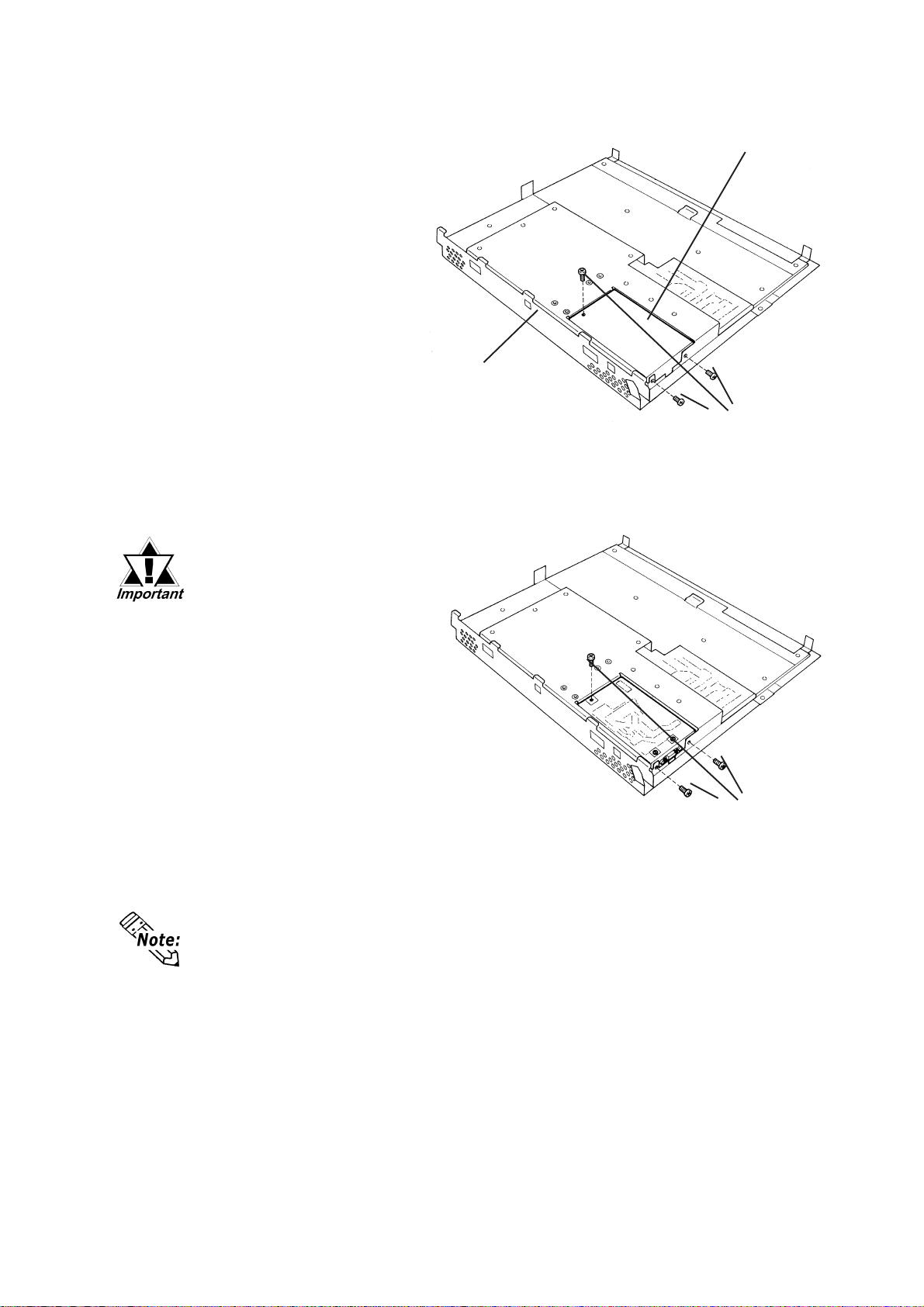
Chapter 3 - Optional Units
5) Unscrew the three (3)
Cover A Attachment
Screws and remove Cover
A (see figure.)
6) After inserting the PL-
PE200, check that the PL
and the PL-PE200 connectors are correctly aligned,
insert the PL-PE200’s three
(3) attachment screws
removed in step 5) and
secure the unit in place.
• Since the PL-PE200 contains precision parts, be
sure to handle it carefully.
Cover A
Rear Part
Attachment
Screws
• Do not push or press on
the PL-PE200 too
strongly, since it may
damage the unit.
7) Reattach the Rear Cover to
the Front Panel, using the
four (4) attachment screws
removed in step 3).
When installing the PL-PE200
in a PL-DU7900-T42, you need
to also re-attach the Side Cover ,
using the two (2) attachment
screws removed in step 2).
Attachment
Screws
3-4 PL-DU6900/PL-DU7900 User Manual
Page 30
Chapter 3 - Optional Units
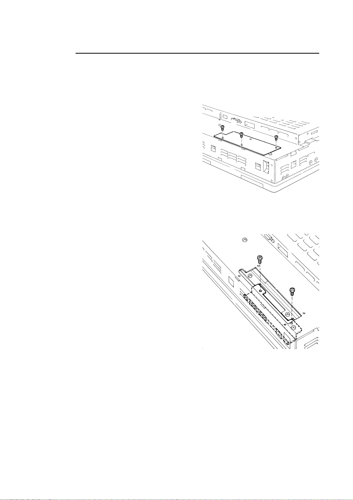
3.1.2 Installing the USB Front Access Unit (PL-US200)
Use the following procedure to install the PL-US200 in the DU.
1)Unscrew the blank panel’s three (3)
attachment screws and remove the
DU rear face’s PL-US200 blank
panel.
2)Unscrew the PL-US200 front blank
panel’s two (2) screws from inside
the DU’s rear face.
PL-DU6900/PL-DU7900 User Manual
3-5
Page 31
Chapter 3 - Optional Units
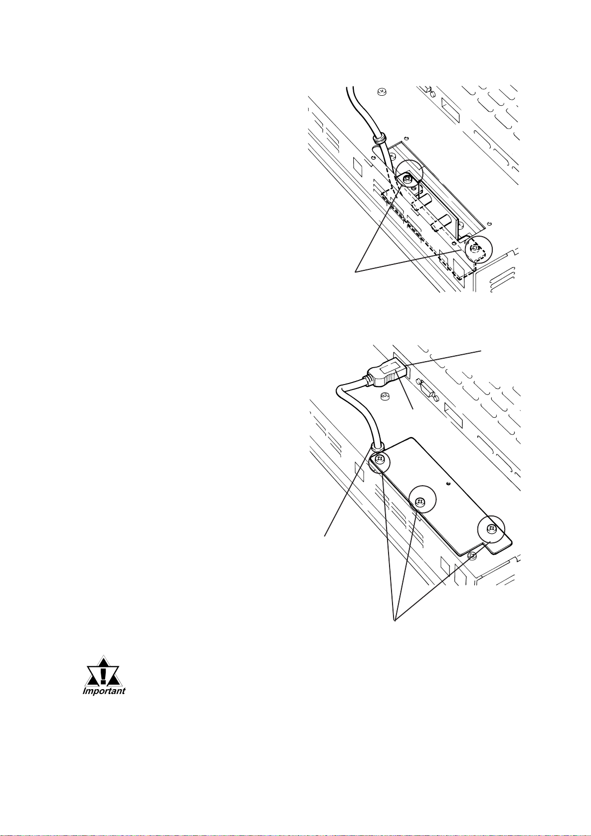
3)Insert the PL-US200 into the PL
and secure it in place with two
(2) attachment screws.
Attachment Screws
4) Insert the PL-US200’s USB
Connector into the DU’s USB
Socket.
5)Insert the PL-US200 cable’s
black Rubber Stopper in the DU
rear panel’s notch. Then, re-
place the PL-US200’s rear
blank panel, rotating it 180°
from its original orientation,
and secure it in place with its
three (3) attachment screws.
USB
Socket
USB
Connector
Rubber
Stopper
Attachment Screws
• Do not pinch the PL-US200 cable against the DU’s chassis or against
other devices.
• Do not pull the PL-US200’s cable too strongly.
3-6 PL-DU6900/PL-DU7900 User Manual
Page 32
1. DU Installation Cautions
2. DU Installation
Chapter
3. Wiring Cautions
4 Installation and Wiring
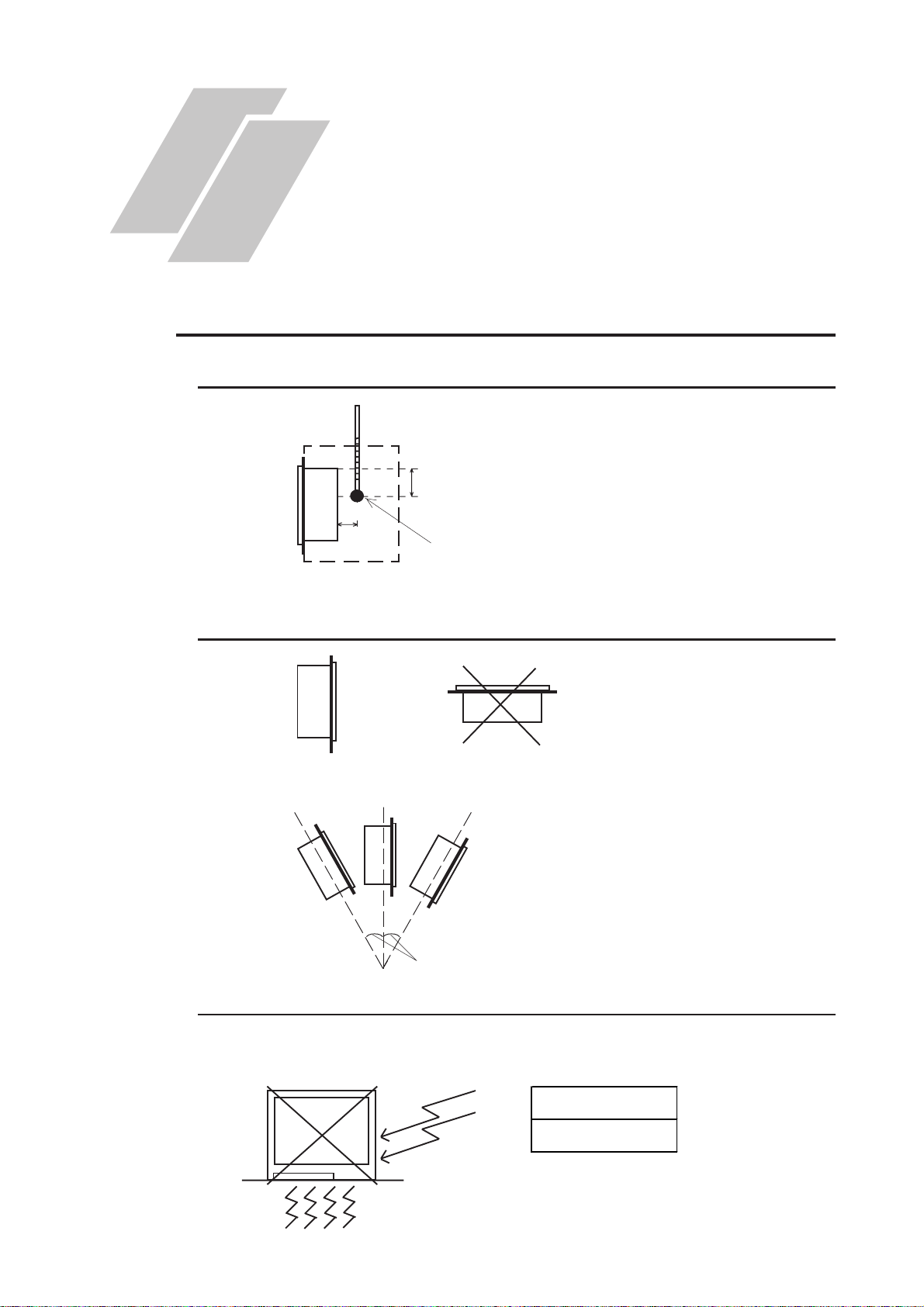
4.1 DU Installation Cautions
4.1.1 Temperature Related Cautions
Be sure to confirm that the area
near the DU will be within the
allowable temperature range by
placing a temperature sensor in
the location shown in the left-side
drawing. If this area’s temperature
exceeds the allowed limit, a
machine breakdown can occur.
Front face
of DU
100mm
30mm
T emperature Sensor
0oC to 50oC
4.1.2 Installation Positioning Cautions
Be sure to install the panel in an
upright (vertical) position.
OK
Vertical Installation Horizontal Installation
Also, be sure that the panel’s
viewing angle is tilted no more
than 30 degrees from parallel to
the operator (i.e. directly in front).
No more than 30 degrees of tilt
4.1.3 Shock / Vibration Related Cautions
Be sure to protect the DU from excessive vibration or jolting. These kinds of
shocks can cause the DU to malfunction.
Sho ck Resistance
2.0G
4-1PL-DU6900/PL-DU7900 User Manual
Page 33
Chapter 4 - Installation and Wiring
4.2 DU Installation
4.2.1 Installation
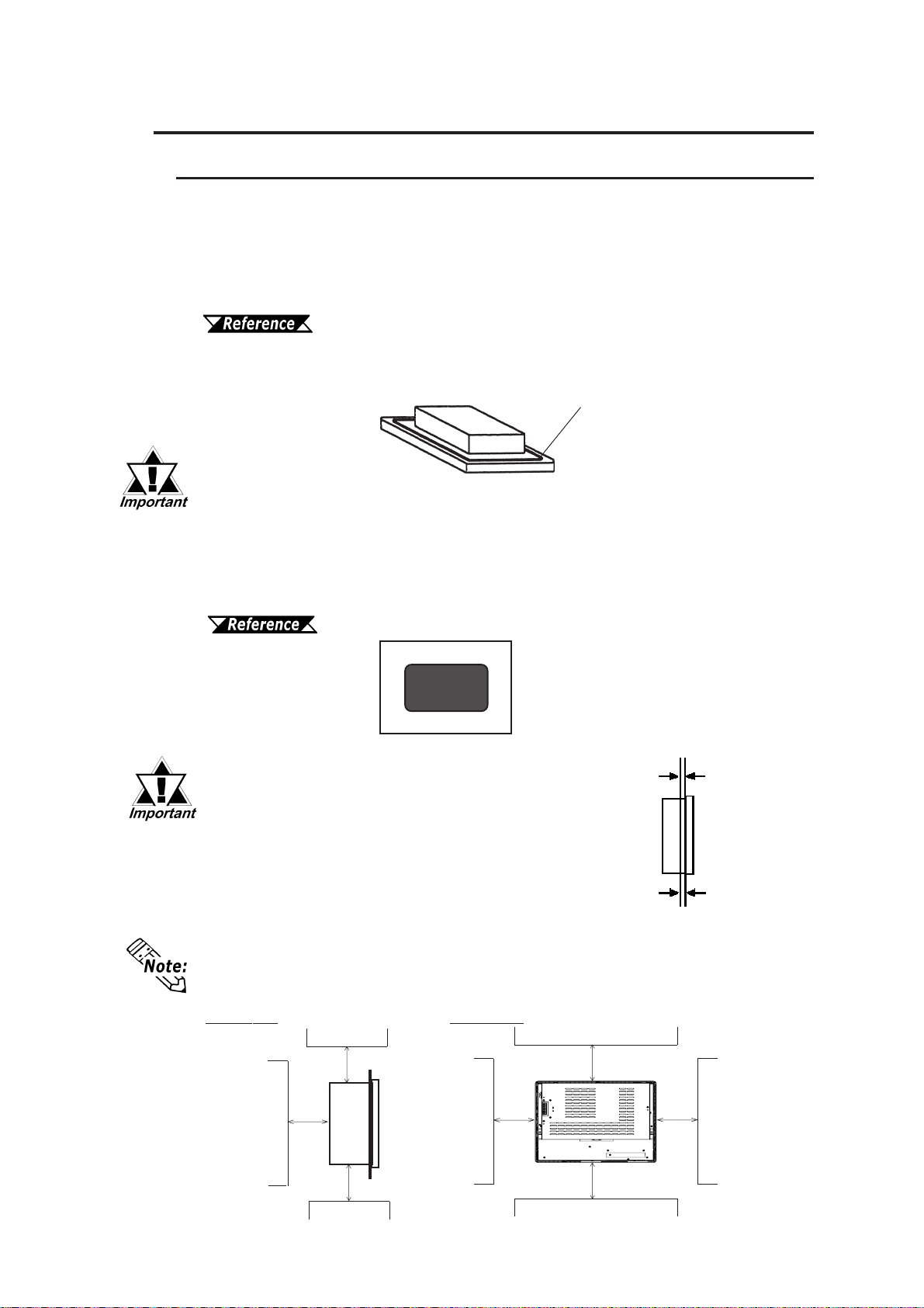
Confirm the Installation Gasket’s Seating
It is strongly recommended that you use the gasket.
Place the DU on a level surface with the display panel facing downward. Check
that the DU’s installation gasket is seated securely into the gasket’s groove, which
runs around the perimeter of the panel’s frame.
For more information about installing the gasket, refer to
5.1.2 Installation Gasket Replacement
Rear
face
Be sure the gasket is in place before installing the DU.
Installation
Gasket
Creating a Panel Cut Out
Create the correct sized opening required to install the DU, using the installation
dimensions given. The moisture resistant gasket, installation fasteners and attach-
ment screws are all required when installing the DU.
2.4 Display Unit Dimensions
Panel
Cut Out
• Check that the installation panel or cabinet's
surface is flat, in good condition and has no
1.6mm to 10.0mm
jagged edges.
• Panel thickness should be from 1.6mm to
10.0mm.
• Be sure to consider the weight of the DU when
designing the panel.
To enhance the DU’s maintainability, operability and ventilation, allow at least 50mm
clearance between the DU and any other objects. (The clearance must be large enough
to allow you to insert or remove expansion boards and to attach connectors.)
Rear ViewSide View
50mm
50mm
50mm
50mm
50mm
50mm
50mm
4-2 PL-DU6900/PL-DU7900 User Manual
Page 34
Chapter 4 - Installation and Wiring
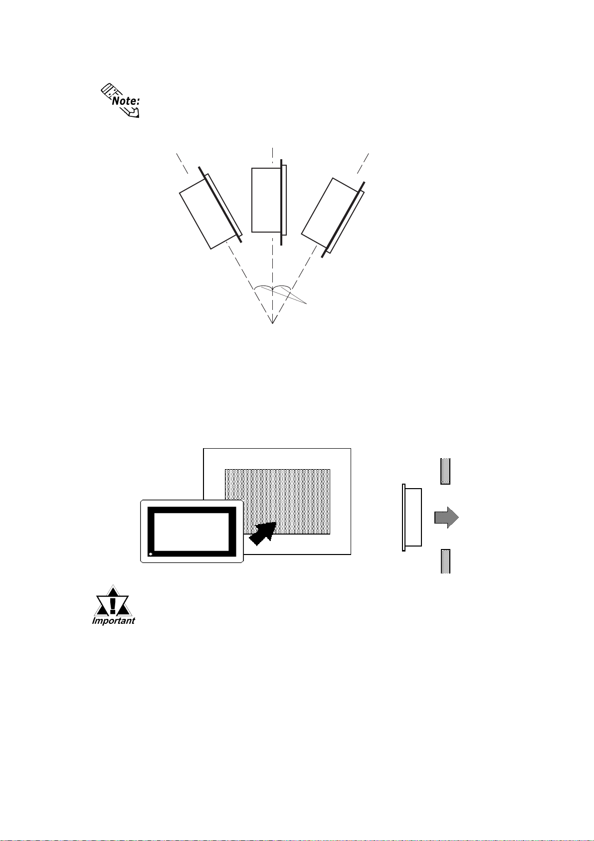
DU Viewing Angle
• The DU must be installed vertically. Also, the DU uses a cooling fan. To operate the
DU correctly, be sure that the panel’s viewing angle is tilted no more than 30 degrees from parallel to the operator (i.e. when the operator is directly in front).
OK
less than 30
from vertical
• Avoid placing the DU next to other devices that might cause overheating.
• Avoid using the DU where the ambient temperature will exceed 50°C.
• Keep the DU away from arc-generating devices such as magnetic switches and non-
fuse breakers.
• Avoid using the DU in environments where corrosive gases are present.
Insert the DU into the Panel Cut Out
OK
o
OK
Panel
Side View
Be sure the installation panel’s actual measurements are the same as
those given in this chapter , otherwise the DU may slip or fall out of the
panel.
PL-DU6900/PL-DU7900 User Manual
4-3
Page 35
Chapter 4 - Installation and Wiring
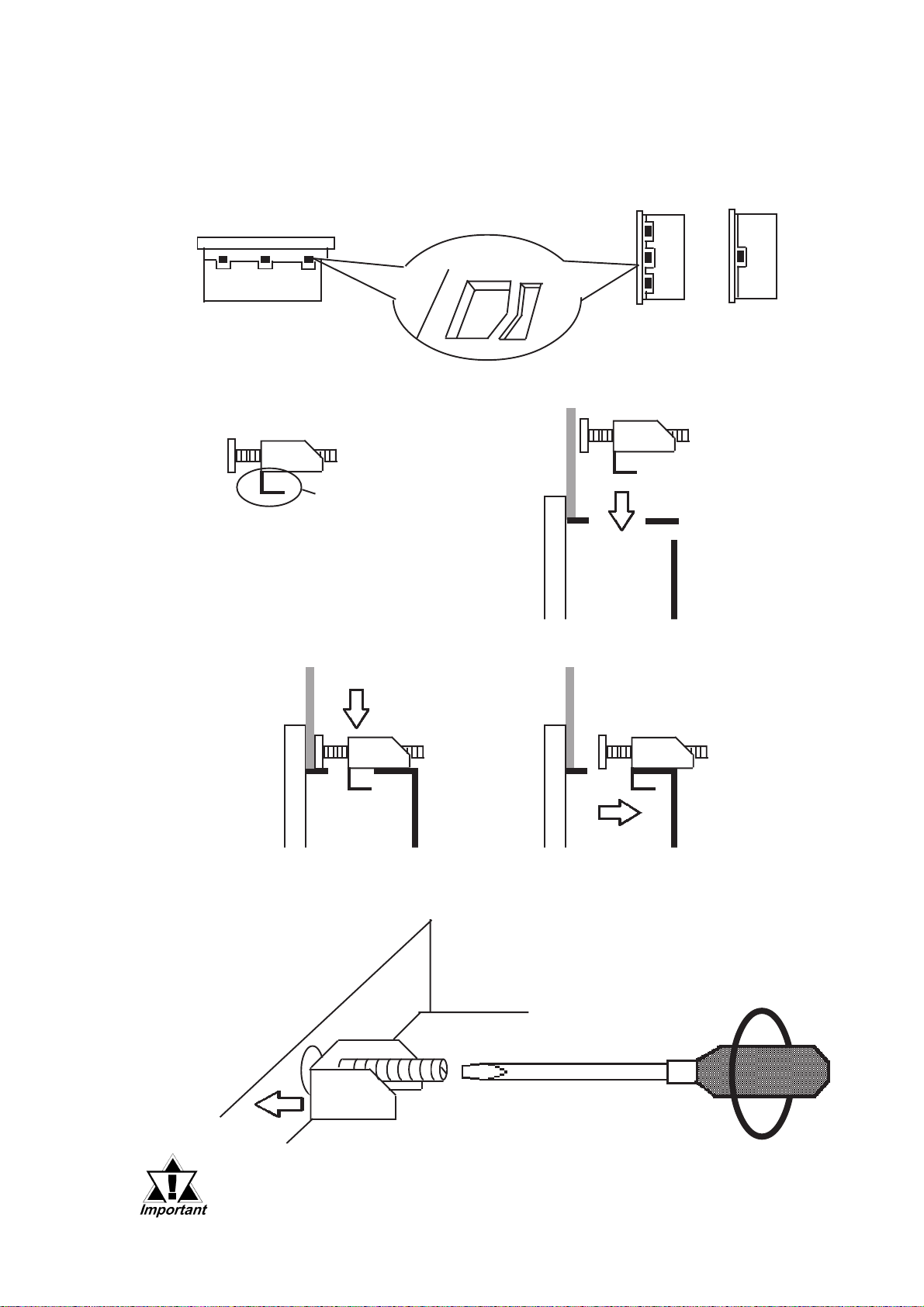
Securing the Installation Fasteners
1) There are eight (8) insertion slots on the top and bottom of the PL-DU6900,
and twelve (12) insertion slots on the top and bottom of the PL-DU7900 where
the metal installation fasteners hook on.
Attachment Hole
Top/Bottom View
2) Insert each fastener into its attachment hole.
Installation Fastener
Panel
Hook
Front Face
3) Slide the fastener backwards until it stops.
PL-DU7900
Side View
(both sides)
Attachment
Hole
PL-DU6900
Side View
(both sides)
Rear Face
4) Use a screwdriver to tighten each bracket’s adjustment screw. To ensure a high
degree of moisture resistance, the torque should be 0.5 to 0.6 N•m.
Panel
DU
▼
▲
Excessive torque may damage the panel or bracket.
4-4 PL-DU6900/PL-DU7900 User Manual
Page 36
Chapter 4 - Installation and Wiring
4.3 Wiring Cautions
4.3.1 Connecting to PL
After connecting the DU to the PL-B900 Series unit and setting up the PL's OS,
you will need to complete the DU's screen settings and touch panel calibration.
For details, refer to BOX-Type Industrial Computer PL-B900/
B910 Series Users Manual.
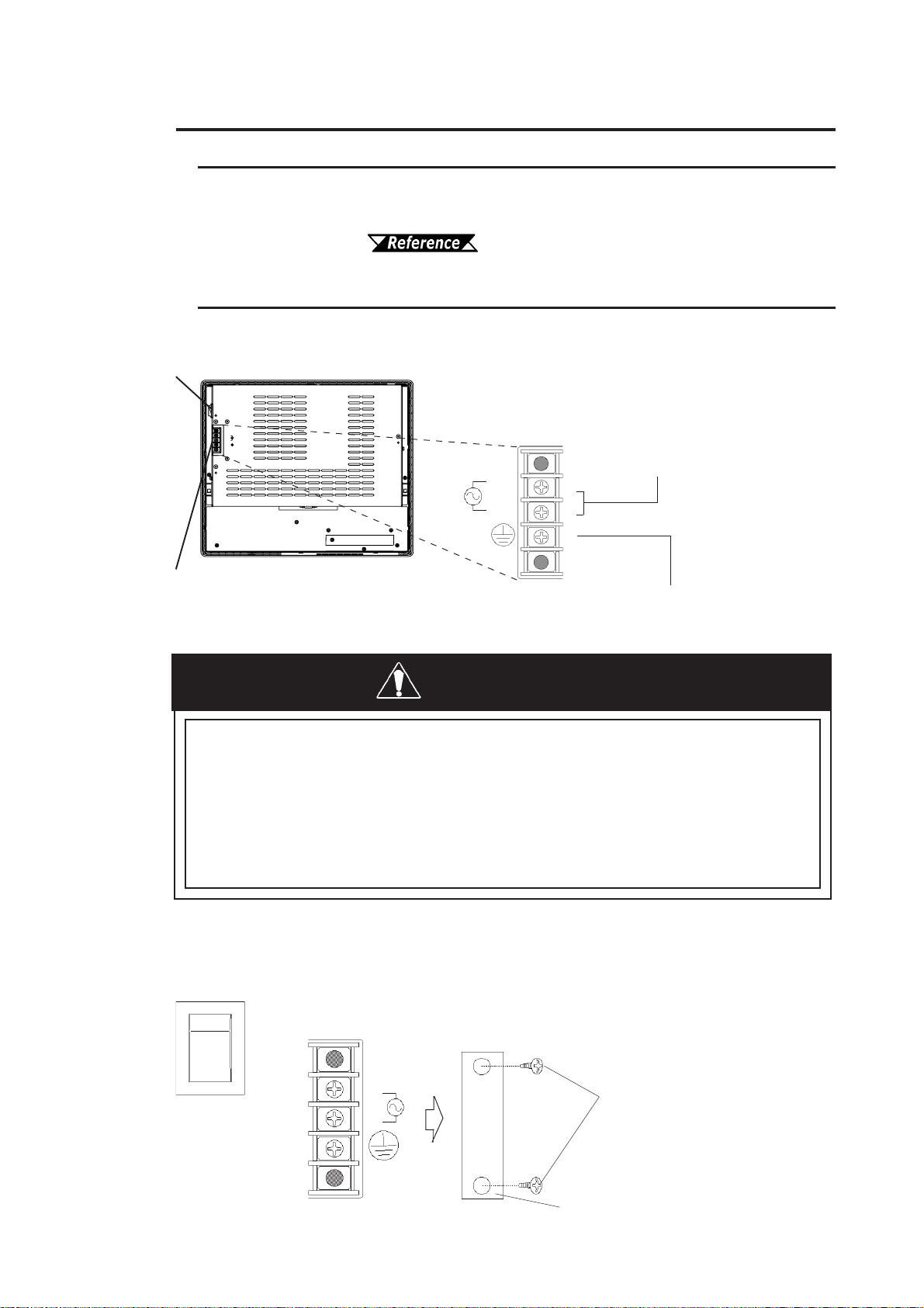
4.3.2 Connecting the Power Cord
(Rear View)
Power Switch
Power Input T erminals
Connecting these two terminals provides AC100V to 240V power.
L= Live and N= Neutral
L
N
(screw size: M3)
Power Terminals
PL-DU6900
FG
This terminal is connected to the
DU’s frame (chassis).
WARNINGS
• To prevent electric shocks, be sure to turn the DU OFF
before connecting the power cord.
• To prevent fires, electrical hazards and equipment dam-
age, be sure to use only the specified power supply voltage when operating the DU.
Use the following steps when connecting the power cord to the DU’s power terminals.
POWER
I
I:ON
o:OFF
1) Confirm that the DU’s power switch is
turned OFF. Then, remove the power
terminal’s transpar ent plastic cover.
o
L
N
FG
PL-DU6900/PL-DU7900 User Manual
Screws
Transparent Cover
4-5
Page 37
Chapter 4 - Installation and Wiring
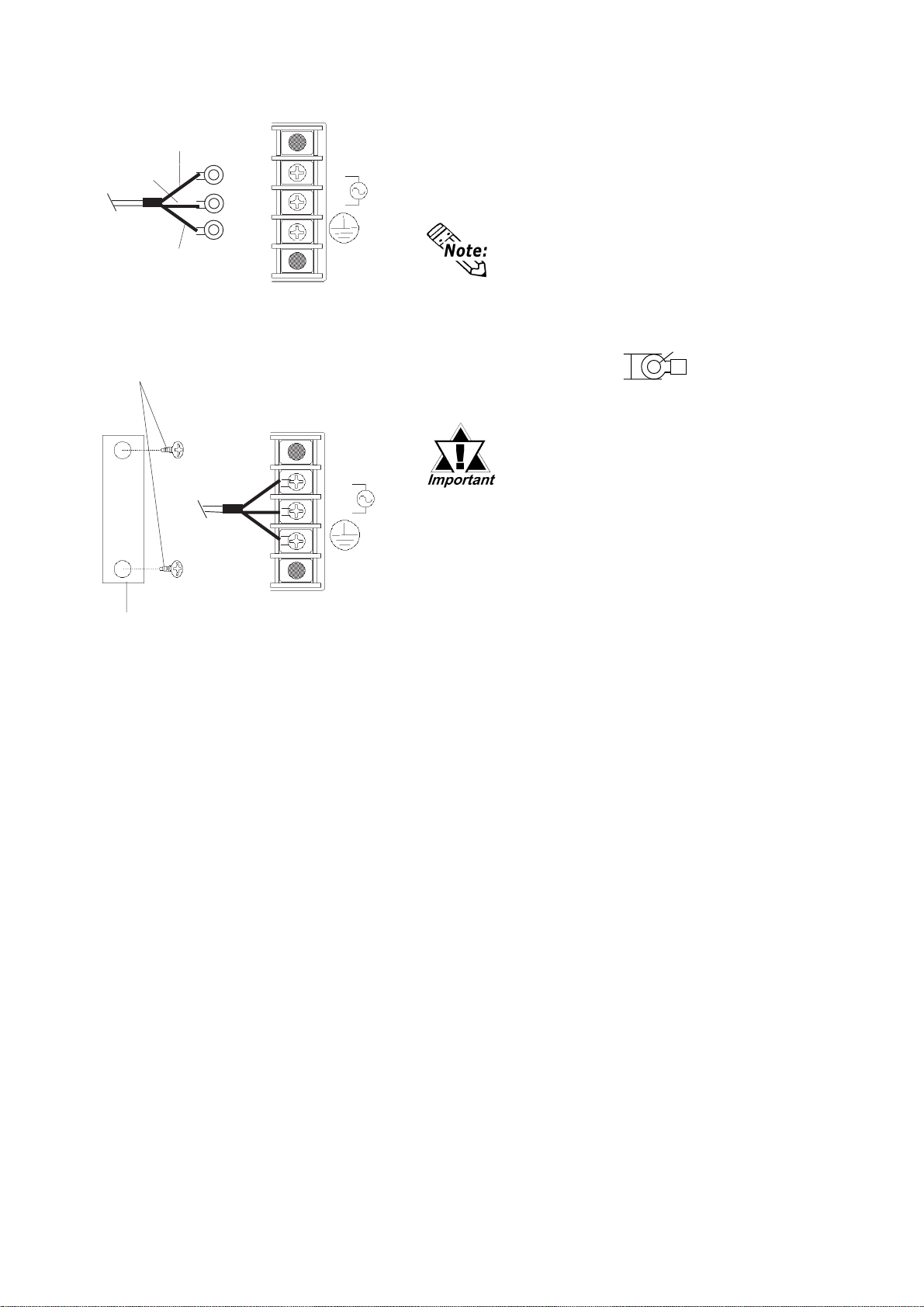
2) Loosen and remove the middle three screws
Black
White
Green/Yellow
Attachment Screws
L
N
FG
L
N
FG
from the terminal strip. Align the crimp
terminals with each screw hole, and tighten the
screws.
• Crimp Terminal Types :
V1.25-3, by J.S.T . or equivalent (JIS standard part number : RAV1.25-3)
• Crimp terminals must be the same as
shown below.
φφ
φ
φφ
3.2 mm or larger
^
Max. 6.0 mm
^
^
• The colors used in the figure
above are for the cord which
came with the DU.
• This power cord is designed only
for AC100V/AC115V use. Be sure
to use a different cable when
using other than AC100V/AC115V
power.
Transparent
Cover
3) Reattach the terminal strip’s transparent cover
and secure it in place with its attatchment
screws.
4-6 PL-DU6900/PL-DU7900 User Manual
Page 38
Chapter 4 - Installation and Wiring
4.3.3 Connecting the DU’s Power Supply
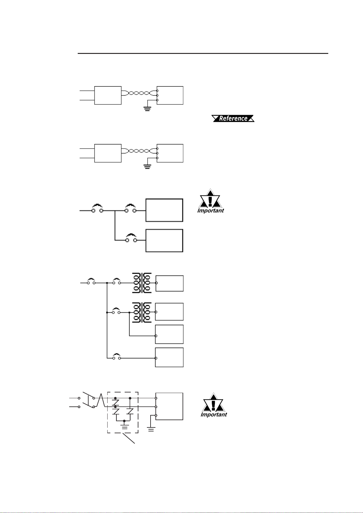
Be sure to follow cautions explained here when connecting the power cord to the
DU’s Power Input Terminals.
Constant
voltage
transformer
Insulating
transformer
Twisted-pair
cable
DU
FG
Twisted-pair
cable
DU
FG
• If voltage fluctuations are expected to
vary beyond the specified range, connect
a constant voltage transformer .
For information about
the specified voltage, refer to
2.1 General Specifications.
• Use a low-noise power supply both
between the lines and between the DU
and its ground. If there is still excess
noise, connect an insulating transformer
(noise-prevention type).
AC 100V
Main power
source
Main power
source
AC200V
DU
power
source
I/O power
source
DU
power
T1
source
T2
I/O power
source
Main circuit
power source
DU
I/O
device
I/O
device
I/O
device
Power
device
DU
Be sure any constant or insulating
transformer used has a capacity of
70VA or more.
• Wire the power cords of the DU, I/O
devices, and power supply devices
separately.
• To improve noise immunity, it is recom-
mended to attach a ferrite core to the
power cord.
• Isolate the main circuit (high voltage,
large current) line, I/O signal lines, and
power cord, and do not bind or group
them together.
• To prevent damage from lightning,
connect a lightning surge absorber.
Lightning surge absorber
AC
E1
Twisted-pair
cable
PL-DU6900/PL-DU7900 User Manual
FG
E2
DU
• Ground the lightning surge
absorber (E1) and the DU
(E2) separately.
• Select a lightning surge
absorber which will not
exceed the allowable
circuit voltage, even when
the voltage rises to the
maximum.
4-7
Page 39

Chapter 4 - Installation and Wiring
4.3.4 Grounding the DU
(a) Dedicated Ground - best
*1
DU
Other
device
*1
(b) Shared Ground - allowed
DU
Other
device
(c) Shared ground - not allowed
DU
Other
device
• Set up a dedicated ground when using the
rear panel’s FG terminal.
• If a dedicated ground is not possible, use a
shared ground, as shown in figure (b).
• The grounding point must be as close to
the DU as possible, and the grounding
wires must be as short as possible. If the
wires must be long, use thick, insulated
wires and run them through conduits.
4.3.5 Cautions When Connecting I/O Signal Lines
• I/O signal lines must be wired separately from the power cord.
• If the power code needs to be wired together with the cord (I/O) signal
lines for any reason, use shielded cables and ground one end of the
shield to the DU’s FG terminal.
• To improve noise immunity, attaching a ferrite core to the power cord is
recommended.
*1 Use a grounding resistance of less than 100 Ω and a 2mm2 or thicker wire, or your country’s
applicable standard. For details, contact your local DU distributor.
4-8 PL-DU6900/PL-DU7900 User Manual
Page 40
Chapter
5 Maintenance
5.1 Regular Cleaning
5.1.1 Cleaning the Display
When the surface or the frame of the display gets dirty, soak a soft cloth in water
with a neutral detergent, wring the cloth tightly, and wipe the display.
• Do not use paint thinner, organic solvents, or a strong acid compound
to clean the unit.
• Do not use hard or pointed objects to operate the touch-screen panel,
since it can damage the panel surface.
1. Regular Cleaning
2. Changing the Backlight
3. Periodic Check Points
Use the optional Screen Protection Sheet when using the DU in extremely dirty or
dusty areas.
5.1.2 Installation Gasket Replacement
The installation gasket protects the DU and improves its water resistance. For
instructions on installing the DU’s gasket, Chapter 4 Installation
and Wiring.
A gasket which has been used for a long period of time may have scratches or dirt on
it, and could have lost much of its water resistance. Be sure to change the gasket periodically (or when scratches or dirt become visible).
5-1PL-DU6900/PL-DU7900 User Manual
Page 41
Chapter 5 - Maintenance
5.2 Changing the Backlight
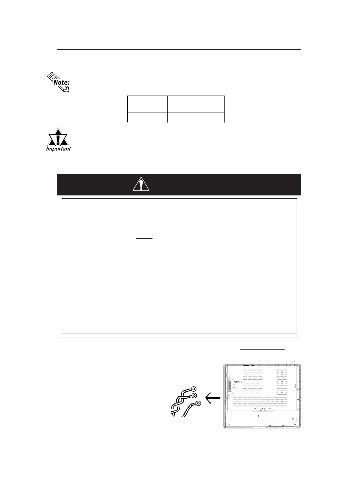
The DU's backlight can be replaced after it has burned out. To replace the backlight, follow the steps shown below.
Please use the following table to identify which backlight model number to use when
ordering your backlight.
If the backlight or the display unit are damaged, the screen display will
go out. Even if the screen goes out, however , there is a possibility that
the touch panel is still operating correctly. Therefore, since any type of
touch panel contact could have an unexpected or dangerous result, be
sure not to touch the screen when this condition occurs.
DU unit Backlight Type
PL-DU6900 GP675T -BL00-MS
PL-DU7900 PL7900T-BL00-MS
WARNINGS
• Whenever changing the backlight, be sure the DU's
power cord has been disconnected.
• When the DU's power has just been turned OFF, the backlight area is still
very hot! Be sure to wear gloves to pre-
vent being burned.
• When the DU's power cord is connected and the DU is
ON, high voltage runs through the wires in the backlight
area—do not touch them!
• Do not try to replace the backlight while the DU is installed in a cabinet or panel. Remove the DU first, then
begin the backlight replacement procedures.
• Do not touch the glass tube. If the glass tube is broken
you may be injured.
Follow the steps shown below to replace the DU's backlight. Be sure to wear
cotton gloves while replacing the backlight to prevent burns.
1) Unplug the DU's power cord
from the main power supply.
If you do not, it may cause an
electric shock.
2) Disconnect the DU power
cord terminals from the DU's
power terminal block.
5-2 PL-DU6900/PL-DU7900 User Manual
Remove
Power Terminals
PL-DU7900
Page 42
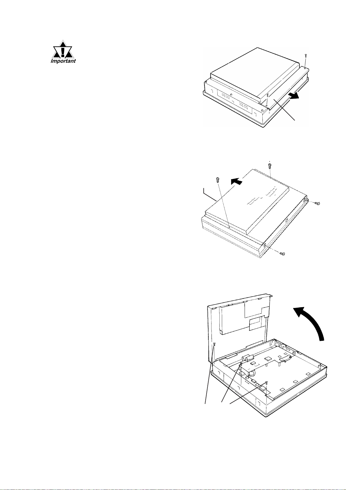
• Be sure to replace the backlight on a flat, level surface.
This will prevent damage to
the DU unit and the accidental cutting of any of its power
cord terminals.
• The PL-DU7900 has a cover.
When replacing the PLDU7900's backlight, you
need to unscrew this cover's
two (2) attachment screws
and remove it.
3) Remove the DU’s four chassis
attachment screws.
4) Hold both sides of the DU’s
front panel section and use your
thumbs to slide (push) the
chassis forward in the direction
shown here (see figure).
Chapter 5 - Maintenance
Cover
Top Face
5) The chassis can then be pivoted
back and open. Remove the three
(3) attachment screws from inside
the Front Unit.
When changing the PL-B6900
backlight, use steps 6) to 13) on
the Page 5-4 to 5-6.
When changing the PL-B7900
backlight, use steps 6) to 14) on
the page 5-7 to 5-8.
PL-DU6900/PL-DU7900 User Manual
Attachment Screws
5-3
Page 43
Chapter 5 - Maintenance
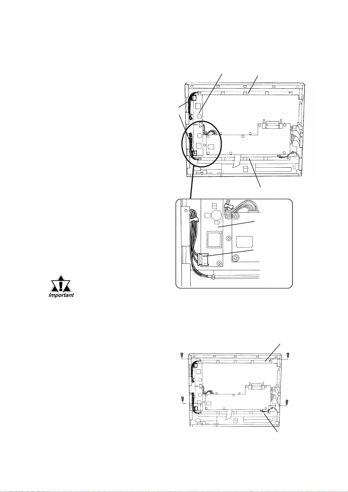
When Changing the PL-DU6900 Backlight
Disconnect both
6)
backlight power
connectors from the
board.
Power
Connectors
Board
Backlight
Backlight
7) Each backlight (upper
and lower) is fixed in
place with two (2)
attachment screws.
Remove these 4
screws.
• Use an"0" sized
Phillips screwdriver
to remove the backlight attachment
screws.
• Be careful not to lose
any of the small attachment screws.
• Do not let any of attachment screws fall
inside the DU unit’s
chassis or front panel
area, since it could
cause an electrical
short when the DU's
power is turned ON
again.
Board
Power
Connector
Backlight
Backlight
5-4 PL-DU6900/PL-DU7900 User Manual
Page 44
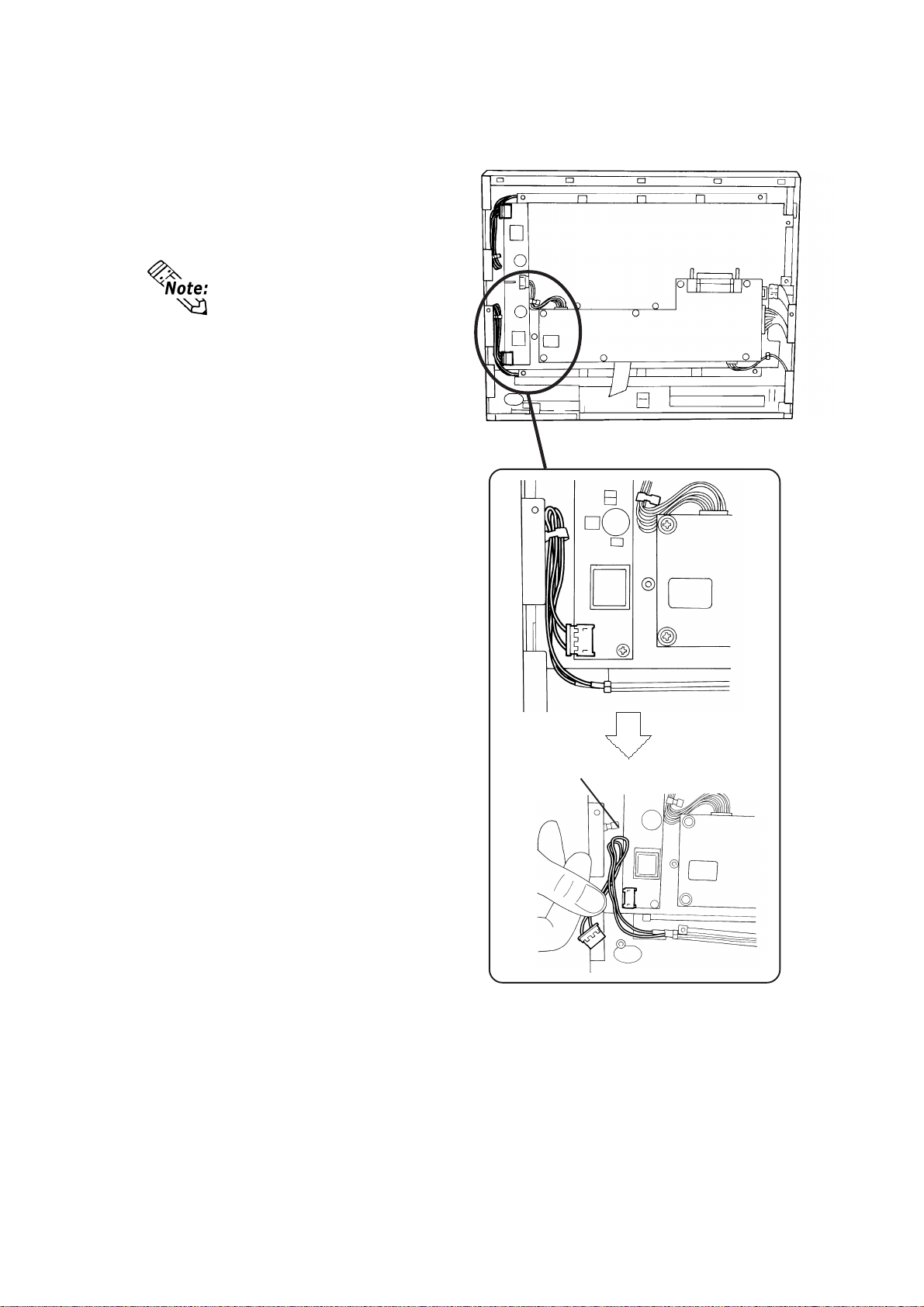
8) Open/release each
plastic cable holder .
Each backlight uses a cable
holder to prevent the cable
from becoming caught or
pinched when the DU’s r ear
cover is opened or closed.
Be sure both cables are secured by their holder before
closing the rear cover.
Chapter 5 - Maintenance
Cable Holder
PL-DU6900/PL-DU7900 User Manual
5-5
Page 45
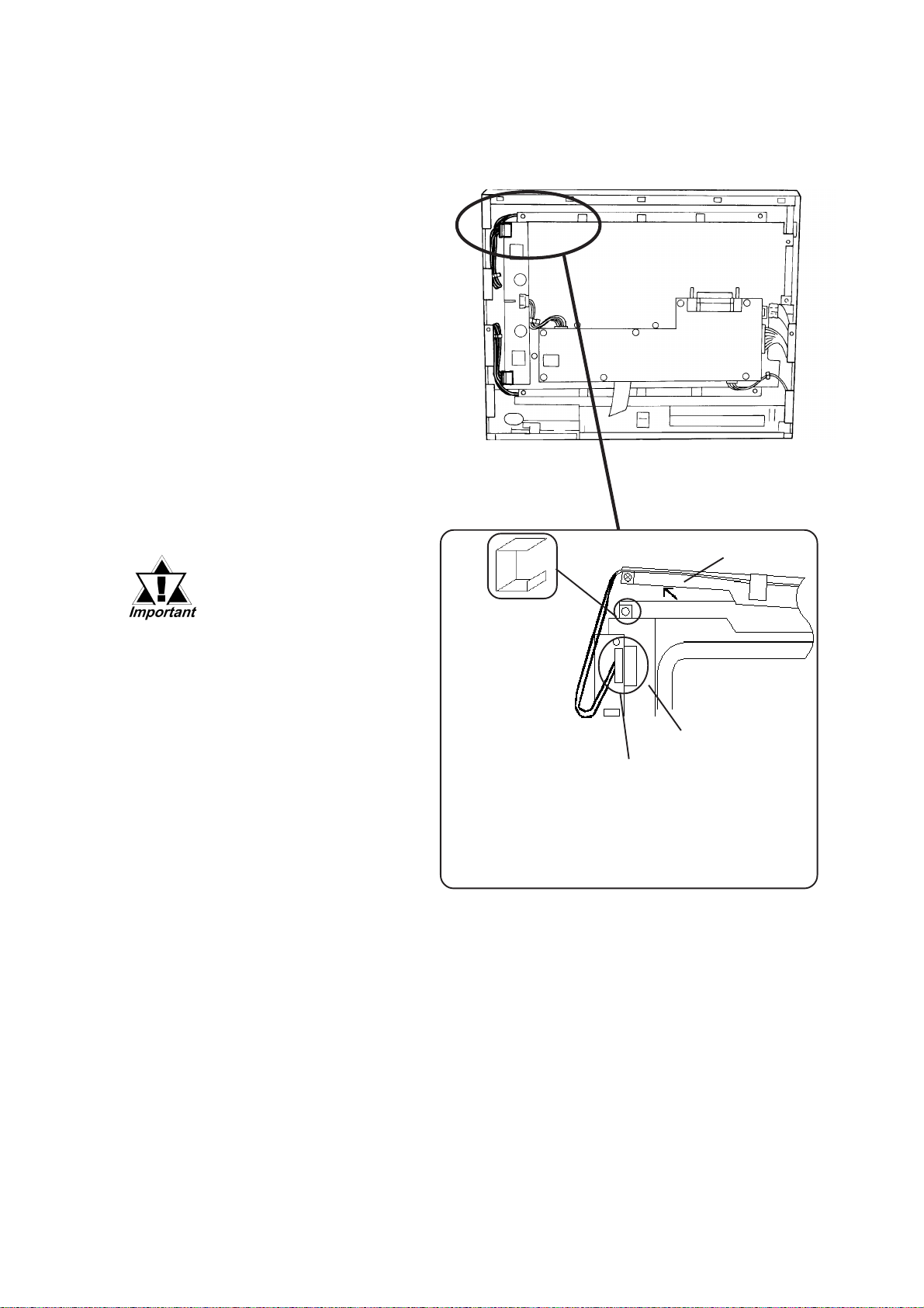
Chapter 5 - Maintenance
9) Remove each backlight
unit.
10) Insert each new back-
light. Be sure to hold the
new backlights with the
metal clips.
11) After installing both new
backlights using steps 9)
to 10), replace and
tighten all attachment
screws (total of 4
screws). Then, reconnect both board
power connectors.
• Be sure to always
change both DU backlights at the same time.
• Be sure that the
backlight’s power cord
connector is inserted
completely into
theboard’s receptacle. If
not, the DU may be damaged.
12) Reattach the rear cover,
being careful not to
pinch any internal
electrical wires.
13) Replace and tighten the
DU Rear face's four
chassis attachment
screws.
When Removing the backlight unit, be
sure not to lose
any of four (4)
metal clips
used to hold
the backlight in
place, or their
attachment
screws.
Backlight
Board
Remove the Connector
5-6 PL-DU6900/PL-DU7900 User Manual
Page 46
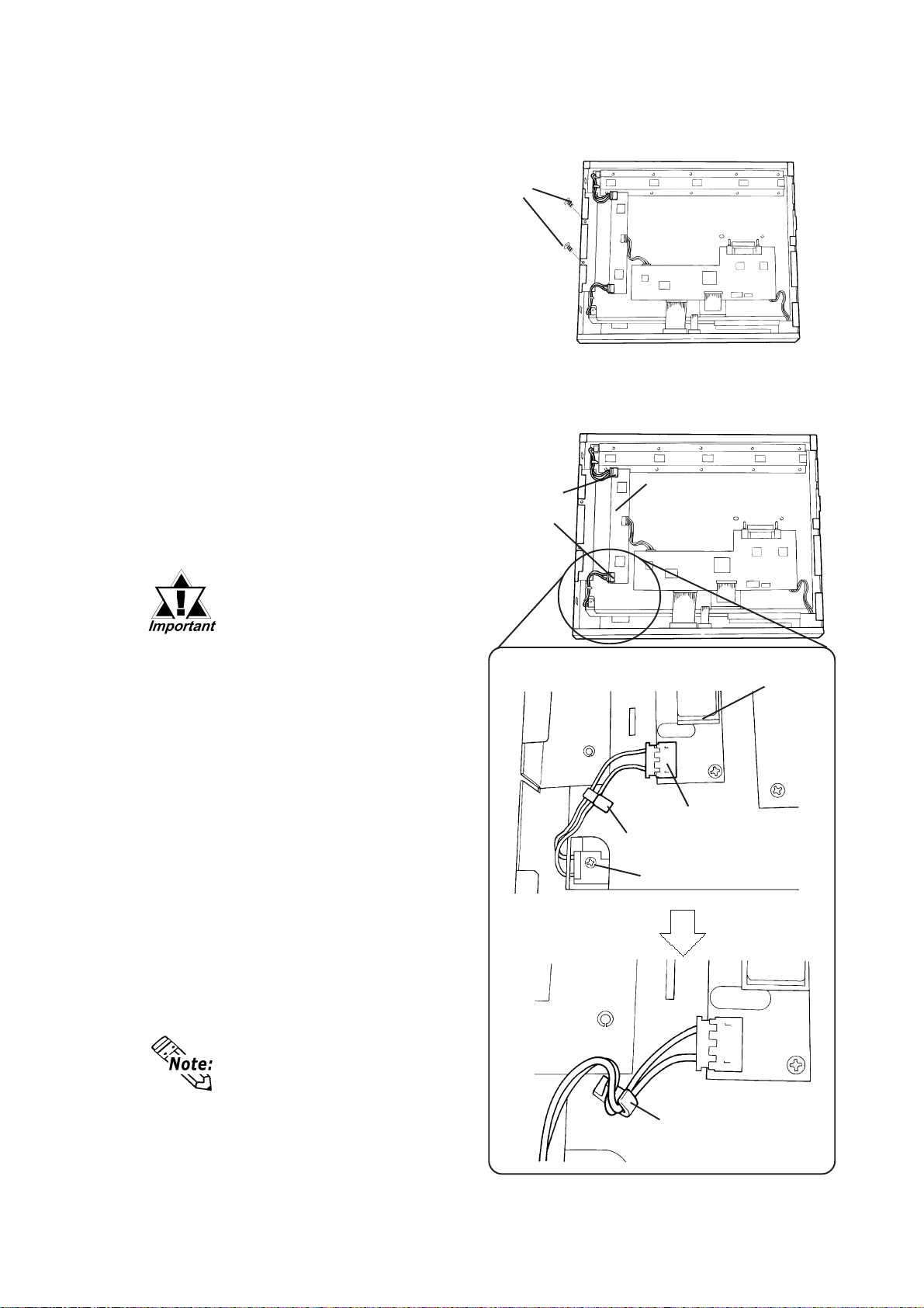
Chapter 5 - Maintenance
When Changing the PL-B7900 Backlight
6) The DU’s LCD display
unit is fixed in place with
two (2) attachment
screws. Remove these
screws.
Disconnect both back-
7)
light power connectors
from the Invertor Board.
8) Each backlight (upper and
lower) is fixed in place
with an attachment screw.
Remove each of these
screws.
• Use a "1" sized Phillips
screwdriver to remove
the backlight attachment screws.
• Be careful not to lose
any of the small attachment screws.
Attachment
Screws
Power
Connectors
Invertor
Board
Invertor
Board
• Do not let any of attachment screws fall inside
the DU unit’s chassis or
front panel area, since it
could cause an electrical short when the DU's
power is turned ON
again.
9) Open/release each plastic
cable holder.
Each backlight uses a cable
holder to prevent the cable
from becoming caught or
pinched when the DU’s rear
cover is opened or closed. Be
sure both cables are secur ed by
their holder before closing the
rear cover.
Power Connectors
Cable Holder (closed)
Attachment Screw
Cable Holder (opened)
PL-DU6900/PL-DU7900 User Manual
5-7
Page 47
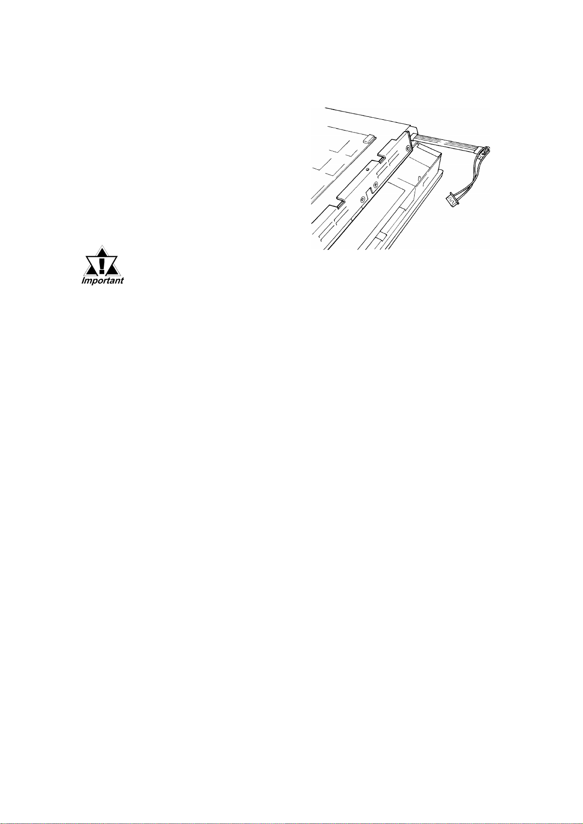
Chapter 5 - Maintenance
10) Remove each backlight unit.
11) Insert each new backlight.
12) After installing both new
backlights using steps 9) to
11), replace and tighten all
backlight and LCD panel
attachment screws (total of 4
screws). Then, re-connect
both board power connectors.
• Be sure to always change
both DU backlights at the
same time.
• Be sure that the backlight’s
power cord connector is inserted completely into the
board’s receptacle. If not, the
DU may be damaged.
13) Reattach the rear cover, being
careful not to pinch any
internal electrical wires.
14) Replace and tighten the DU’s
four chassis attachment
screws.
5-8 PL-DU6900/PL-DU7900 User Manual
Page 48
Chapter 5 - Maintenance
5.3 Periodic Check Points
To keep your DU unit in good working condition, please check the following
points periodically .
DU Operation Environment
• Is the operating temperature within the allowable range?
• Is the operating humidity within the specified range (30% RH to 85% RH)?
• Is the operating atmosphere free of any corrosive gasses?
Electrical Specifications
• Is the input voltage appropriate (AC85V to AC265V 50/60Hz) ?
Related Items
• Are all cables connected properly? Have any become loose?
• Are all mounting brackets holding the unit securely?
• Are there many scratches or traces of dirt on the moisture resistant gasket?
Display Check
• Is the display bright enough ?
When the DU’s backlight needs to be r eplaced, please contact your local DU distributor.
PL-DU6900/PL-DU7900 User Manual
5-9
Page 49

Memo
Page 50

Index
Index
A
About PL-DU*900 Models ...................................... 8
Accessories ............................................................ 1-5
B
backlight type ........................................................ 5-2
Brightness Adjustment Slide ................................. 2-4
C
CE Marking Notes...................................................11
Changing the Backlight ......................................... 5-2
Cleaning the Display ............................................. 5-1
Connecting I/O Signal Lines ................................. 4-8
Connecting the DU's Power Supply ...................... 4-7
Connecting the Power Cord .................................. 4-5
Connecting to PL................................................... 4-5
Crimp Terminal Types ........................................... 4-6
D
Display Area.......................................................... 2-4
Display Specifications........................................... 2-3
Display Unit Dimensions ...................................... 2-5
Documentation Conventions .................................... 8
E
electric hazards ...................................................... 3-1
Electrical Specifications........................................ 2-1
Environmental Specifications ............................... 2-1
Essential Safety Precautions..................................... 2
F
Front Maintenance Cover...................................... 2-4
Full Sized Cover Attachment Dimensions ....1-2, 1-3
Functional Specifications ...................................... 2-3
G
General Safety Precautions ...................................... 5
General Specifications .......................................... 2-1
Grounding.............................................................. 4-8
H
Hardware Reset Switch ......................................... 2-4
I
Icon Meaning............................................................ 2
Insert the DU into the Installation Slot ................. 4-3
Installation ............................................................. 3-1
Installation and Wiring.......................................... 4-1
Installation Cautions.............................................. 4-1
Installation Gasket................................................. 4-2
Installation Gasket Replacement....................4-2, 5-1
Installation Positioning Cautions .......................... 4-1
Introduction ........................................................... 1-1
IrDA....................................................................... 2-4
K
Keyboard Connector ............................................. 2-4
L
LCD Handling Caution ............................................ 4
LCD Usage and Handling ........................................ 5
M
Maintenance .......................................................... 5-1
Maintenance Options.....................................1-2, 1-3
Moisture Resistant Gasket..................................... 4-2
Moisture Resistant Gasket Replacement....... 4-2, 5-1
moisture resistant seal ........................................... 4-2
N
Names and Functions ............................................ 2-4
P
Package Contents ................................................... 10
Panel Installation Opening .................................... 4-2
panel thickness .............................................. 2-6, 4-2
PL-DU7900 Installation Fasteners........................ 2-6
Performance Specifications................................... 2-3
Periodic Check Points ........................................... 5-9
PL Connector......................................................... 2-4
PL Installation ....................................................... 3-1
PL-DU*900 Features................................................ 9
PL-DU*900 Installation ........................................ 4-2
PL-DU6900 External Dimensions ....................... 2-5
PL-DU6900 Installation Fasteners........................ 2-6
PL-DU7900 External Dimensions ....................... 2-5
PL-DU7900 Installation Fasteners........................ 2-6
PL-DU6900/PL-DU7900 User Manual
Index-I
Page 51

Index
Power Input T erminals .......................................... 4-5
Power Switch......................................................... 2-4
Power T erminals.................................................... 2-4
Preface ...................................................................... 1
Prior to Using the DU .............................................. 5
R
Regular Cleaning ................................................... 5-1
S
Securing the Installation Fasteners........................ 4-4
Shock / Vibration Related Cautions...................... 4-1
Specifications ........................................................ 2-1
Status LED............................................................. 2-4
Structural Specifications ....................................... 2-2
System Design ....................................................... 1-1
T
Table of Contents ..................................................... 6
Temperature Related Cautions ......................3-5, 4-1
Touch Panel ........................................................... 2-4
U
UL/c-UL(CSA) Application Notes .........................11
V
Viewing Angle....................................................... 4-3
W
Wiring Cautions..................................................... 4-5
Index-II
PL-DU6900/PL-DU7900 User Manual
 Loading...