


PL-6920/PL-7920 Series
Panel Computer
User Manual
When printing out this PDF manual, since the printer setting can effect the
quality of the printout, be sure your printer’s quality setting is set to “H igh”.

Introduction
The PL-6920/PL-7920 series (PL) of Panel Computers are multipurpose
factory automation (FA) computers, which embody Pro-face’s latest, costeffective architecture. Before using the PL, read this manual thoroughly to
familiarize yourself with the PL’s operation procedures and functions.
Preface
NOTE:
1. It is forbidden to copy the contents of this manual in whole, or in part, without the permission of the Digital Electronics Corporation.
2. The information in this manual is subject to change without notice.
3. This manual was written with care; however, if you should find any error or omissions,
please contact Digital Electronics Corporation and inform them of your findings.
4. Regardless of the above clause, Digital Electronics Corporation shall not be held responsible for any damages or third-party claims for damages or losses resulting from the use
of this product.
Product names used in this manual are the trademarks of their respective manufacturers.
Copyright 2004, Digital Electronics Corporation
©
Windows® 95 OSR2 or later, Windows® 98 SE, Windows NT® 4.0, and Windows
2000 are registered trademarks of the Microsoft Corporation.
®
PL-6920/PL-7920 Series User Manual
1

Preface
Essential Safety Precautions
This manual includes the following cautions concerning procedures that must be
followed to operate the PL correctly and safely . Prior to operating the PL, be sure to
read this manual and any related materials thoroughly to understand the correct operation and functions of this unit.
Safety Icons
To allow you to use the PL correctly, throughout this manual, the following icons
are provided next to operations requiring special attention. These icons are used to
describe the following situations:
Indicates situations where severe bodily
W arning
Caution
injury, death or major equipment damage
may occur .
Indicates situations where slight bodily
injury or machine damage can occur.
WARNINGS
• To avoid the possibility of an electric shock, be sure to
disconnect the power cord to the PL before connecting it
to the main power supply.
• A fire or electrical shock may occur if voltages used with
the PL are beyond the specified range. Be sure to use only
the specified voltage.
• Before opening the PL’s protective cover, be sure to turn
the unit’s power OFF. This is because the PL’s internal
parts carry high voltages.
• To avoid fires or electrical hazards, do not modify the PL in
any way.
• Do not create touch panel switches that are used to either
control or to ensure the safety of equipment and personnel. Mechanical switches, such as an emergency stop
switch, a deadman (two-handed) start switch, etc., must
be installed and operated via a separate control system.
2
PL-6920/PL-7920 Series User Manual

Preface
WARNINGS
• Do not create touch panel switches which could possibly
endanger the safety of humans and equipment. This is due
to the possibility of a malfunction in the PL or its cable(s),
causing the output of a signal that could result in a major
accident. All of a system’s major, safety-related switches
should be designed to be operated separately from the PL.
• After the PL’s backlight burns out, unlike the PL’s
“Standby Mode”, the touch panel is still active. If the operator fails to notice that the backlight is burned out and
touches the panel, a potentially dangerous machine missoperation can occur.
If your PL's backlight suddenly turns OFF, use the following
steps to determine if the backlight is actually burned out.
1) If your PL is
has gone blank, your backlight is burned out.
2) Or , if your PL
screen does not cause the display to reappear, your
backlight is burned out.
• If metal particles, water or other types of liquids contact
any of the PL’s internal parts, immediately turn the unit’s
power OFF, unplug the power cord, and contact either
your PL distributor or the Digital Electronics Corporation.
• Read and understand Chapter 4 “Installation and Wiring”
thoroughly in order to select an appropriate installation
location for the PL.
• Before either plugging in or unplugging a board or inter-
not set to "Standby Mode" and the screen
is set to Standby Mode, but touching the
face connector, be sure to turn the PL’s power OFF.
PL-6920/PL-7920 Series User Manual
3

Preface
WARNINGS
• To prevent a possible explosion, do not install the PL in
areas containing flammable gases.
• The PL is not appropriate for use with aircraft control
devices, aerospace equipment, central trunk data transmission (communication) devices, nuclear power control
devices, or medical life support equipment, due to these
devices’ inherent requirements of extremely high levels of
safety and reliability.
• When using the PL with transportation vehicles (trains,
cars and ships), disaster and crime prevention devices,
various types of safety equipment, non-life support related medical devices, etc. redundant and/or fail-safe
system designs should be used to ensure the proper degree of reliability and safety.
CAUTIONS
• Do not push on the PL’s screen too strongly, with either
your finger or with a hard object. Excessive pressure can
scratch, crack or damage the screen. Also, do not use a
pointed object, such as a mechanical pencil or screwdriver, to press any of the touch panel’s switches, since
they can damage the display.
• If the screen becomes dirty or smudged, moisten a soft
cloth with diluted neutral detergent, wring the cloth well,
and wipe the display. Do
vents.
• Avoid exposing the PL to, or operating the PL in direct
sunlight, high temperatures and humidity, and in areas
where excessive dust and vibration will occur.
4
not use thinner or organic sol-
PL-6920/PL-7920 Series User Manual

Preface
CAUTIONS
• Avoid using the PL in areas where sudden, extreme
changes in temperature can occur. This may cause condensation to form inside the unit, possibly leading to an
accident.
• To prevent the PL from overheating, be sure its air circu-
lation vents are clear and clean, and keep the unit’s
operation area well-ventilated.
• Avoid operating or storing the PL near chemicals, or
where chemicals can come into contact with the unit.
When PL Hard Disk (HDD) data is lost:
• The Digital Electronics Corporation cannot be held re-
sponsible or provide any compensation for damage(s)
caused by the loss of data stored in the PL’s hard disk
drive (HDD). It is therefore strongly suggested that all
important data and software be backed up regularly to
an external data backup device.
• Please be aware that the Digital Electronics Corporation
bears no responsibility for any damages resulting from
the customer’s application of this unit’s hardware or
software.
• Since the PL unit’s hard disk drive (HDD) is a consumable item, i.e. it has a limited lifetime, be sure to back up
its data regularly and prepare a spare HDD unit.
• To prevent file data damage, be sure to shut down the
PL’s OS before turning OFF the main power.
• After turning OFF the PL's power, wait until the internal
HDD stops spinning before turning on the power again
(approx. 5 seconds).
• When the PL unit's standard display is connected to the
PL using the USB connection, wait three (3) seconds
before turning the power ON again.
PL-6920/PL-7920 Series User Manual
5

Preface
LCD Usage and Handling
The PL’s LCD contains a strong irritant. If the panel is ever cracked and the
LCD’s liquid contacts your skin, be sure to wash it with running water for at
least 15 minutes. If any of this liquid should enter your eye, be sure to flush your
eye with running water for more than 15 minutes and see a doctor as soon as
possible.
The brightness of the LCD screen will depend on the screen’s current display
and the LCD’s contrast adjustment. Any brightness variations that result are
normal for LCD displays.
There are minute grid-points (Dark or Light points) on the LCD surface. These
points are not defects and are a part of the PL unit’s design.
The displayed color will look different when viewed from an angle outside the
specified view angle. This is also normal.
When installing this unit, be sure that the screen is viewable from within the
designated viewing angles. The screen image being difficult to see from outside
its recommended viewing angle is normal.
Displaying a single screen image for long periods of time can cause an afterimage
to remain on the screen. To correct this, turn the unit OFF for 5 to 10 minutes,
then ON again. This phenomenon is a common attribute of LCD displays, and
is not a defect. To prevent this effect, you can:
1) Use the Display OFF feature; if the same image is to be displayed for a long
period of time.
2) Change the screen display periodically to prevent the displaying of a single
image for a long period of time.
6
PL-6920/PL-7920 Series User Manual

Preface
Table of Contens
Introduction ..............................................................................................................1
Essential Safety Precautions ...................................................................................2
Table of Contens ......................................................................................................7
Information Symbols...............................................................................................11
PL Series Panel T ypes...........................................................................................11
Package Contents .................................................................................................12
PL Series Features................................................................................................13
UL/c-UL (CSA) Application Notes ..........................................................................14
CE Marking ...........................................................................................................15
Chapter 1 Overview
1-1 Prior To Using the PL...................................................................................1- 1
1 Setting Up the Touch Panel Connection ..................................................1- 2
2 Using the USB Interface .........................................................................1- 2
3 Using the LAN Interface ..........................................................................1- 3
1-2 System Configuration ..................................................................................1- 3
1-3 Options .......................................................................................................1 - 4
Chapter 2 Specifications
2-1 General Specifications ................................................................................2- 1
1 Electrical Specifications ..........................................................................2- 1
2 Environment Specifications .....................................................................2- 2
3 Dimensions.............................................................................................2- 3
2-2 Performance Specifications.........................................................................2- 4
1 Performance Specifications ....................................................................2- 4
2 Display Functions....................................................................................2- 4
3 Expansion Slots ......................................................................................2- 5
4 Clock(RTC) Accuracy..............................................................................2- 5
2-3 Interface Specifications ...............................................................................2- 6
1 Printer Interface (LPT1) ..........................................................................2- 6
2 Keyboard Interface ..................................................................................2- 7
3 Mouse Interface.......................................................................................2- 7
4 RS-232C Interface (COM1/COM2/COM3)...............................................2- 8
5 RAS Interface..........................................................................................2 - 9
6 USB Interface........................................................................................2- 10
PL-6920/PL-7920 Series User Manual
7

Preface
2-4 Part Names and Features .........................................................................2- 1 1
2-5 PL Dimensions..........................................................................................2- 13
1 General Dimensions .............................................................................2- 13
2 External Dimensions (with Installation Fasteners installed) ....................2- 17
3 PL and RS-232C/RS-485 Conversion Unit (PL-RC500) Dimensions.....2- 21
4 Full Sized Cover Attachment Dimensions .............................................2- 25
5 Panel Cut Dimensions..........................................................................2- 26
6 Installation Fasteners.............................................................................2- 28
Chapter 3 Installing Optional Units and Expansion Boards
3-1 Installing Options and Expansion Boards .....................................................3- 1
1 Removing the Rear Maintenance Cover ..................................................3- 2
2 Installing the DIM Module (PL-EM500 / PL-EM128/ PL-EM256) ..............3- 4
3 Installing the FDD Unit (PL-FD200) .........................................................3- 5
4 Installing the FDD Unit (PL-FD210) .........................................................3- 6
5 Removing / Installing the HDD Unit (PL-HD220/PL-HDX920-W2k/ML) ....3- 8
6 Installing an Expansion Board..................................................................3- 9
7 Connecting the CD-ROM Unit (PL-DK200)............................................3- 10
8 Removing the Electric Fan Unit.............................................................3- 11
Chapter 4 Installation and Wiring
4-1 Installing the PL ...........................................................................................4- 1
1 Installation Caution ..................................................................................4- 1
2 Installation Procedures ............................................................................4- 3
4-2 Wiring the PL ..............................................................................................4- 7
1 Connecting the Power Cord ....................................................................4- 7
2 Power Supply Cautions ...........................................................................4- 9
3 Grounding Cautions ..............................................................................4- 10
4 Cautions When Connecting I/O Signal Lines..........................................4- 10
Chapter 5 System Setup
5-1 Setup Procedures .......................................................................................5- 1
5-2 System Parameters.....................................................................................5- 2
1 STANDARD CMOS FEATURES ............................................................5- 2
2 IDE HDD AUTO DETECTION .................................................................5- 4
3 ADVANCED BIOS FEATURES ..............................................................5- 5
4 ADVANCED CHIPSET FEATURES .......................................................5- 8
8
PL-6920/PL-7920 Series User Manual

Preface
5 INTEGRA TED PERIPHERALS .............................................................5- 10
6 POWER MANAGEMENT SETUP.........................................................5- 13
7 PNP/PCI CONFIGURA TION ..................................................................5- 15
8 IRQ Resources......................................................................................5- 16
9 DMA Resources....................................................................................5- 1 7
10PC Health Status ..................................................................................5- 18
11Frequency/V oltage Control ....................................................................5- 20
12Load Fail-Safe Defaults ........................................................................5- 21
13Load Optimized Defaults.......................................................................5- 21
14Set Supervisor Password......................................................................5- 21
15Set User Password ...............................................................................5- 21
16Save & Exit Setup .................................................................................5- 22
17Exit Without Setting ...............................................................................5- 22
Chapter 6 Setting Up Your PL OS
6-1 CD-ROM Contents ...................................................................................... 6-1
1 Diagram.................................................................................................. 6-1
6-2 Setting Up Your PL OS ................................................................................ 6-2
1 Setting Up HDD with no installed OS....................................................... 6-2
2 Setting Up OS preinstalled HDD ............................................................. 6-5
6-3 Installing Drivers .......................................................................................... 6-6
6-4 Application Features ................................................................................. 6-10
1 Uninstalling PL-X920 Driver and Utility .................................................. 6-12
6-5 Windows NT® 4.0 / Windows® 2000 /Windows® XP Cautions..................... 6-12
1 Automatic System Log-On Setup .......................................................... 6-12
2 Using an Uninterrupted Power Supply.................................................... 6-13
3 When Changing the System Design ...................................................... 6-13
4 Changing to the NTFS File System........................................................ 6-14
Chapter 7 Maintenance and Inspection
7-1 Regular Cleaning.........................................................................................7- 1
1 Cleaning the Display ...............................................................................7- 1
2 Installation Gasket Replacement..............................................................7- 2
7-2 Cleaning the Filter .......................................................................................7- 2
7-3 Changing the PL Backlight...........................................................................7- 4
7-4 Periodic Inspection Items...........................................................................7- 12
PL-6920/PL-7920 Series User Manual
9

Preface
Appendices
A-1 Hardware Configuration........................................................................... App-1
1 I/O Map ............................................................................................... App-1
2 Memory Map ....................................................................................... App-2
3 Interrupt Map ....................................................................................... App-3
A-2 RAS Feature ........................................................................................... App-4
1 PL's RAS Features ............................................................................. App-4
2 RAS Feature Details ........................................................................... App-5
3 RAS Feature Overview...................................................................... App-10
A-3 System Monitor ..................................................................................... App-11
1 Setup Procedure............................................................................... App-11
2 System Monitor Property Settings (PL_Wps.exe) ..............................App-12
3 System Monitor Operation (PL_Smon.exe) ....................................... App-13
4 Error Messages ................................................................................ App-15
5 Error Displays When Using Event Viewer .......................................... App-16
A-4 System Monitor/RAS Feature API-DLL..................................................App-18
1 Operation Environment...................................................................... App-18
2 Class Contents..................................................................................App-20
3 Visual C Functions ............................................................................ App-21
4 Visual C Function S pecifications (Det ails).........................................App-22
5 Visual C++ Functions ........................................................................ App-42
6 Visual C++ Function S pecifications (Details).....................................App-43
7 Visual Basic Functions......................................................................App-72
8 Visual Basic Function S pecifications (Det ails)................................... App-73
A-5 Backlight Control API-DLL..................................................................... App-95
1 Operation Environment...................................................................... App-95
2 Class Contents..................................................................................App-97
3 Visual C Functions ............................................................................ App-98
4 Visual C Function S pecifications (Det ails).........................................App-98
5 Visual C++ Functions ...................................................................... App-100
6 Visual C++ Function S pecifications (Details)...................................App-100
7 Visual Basic Functions....................................................................App-103
8 Visual Basic Function S pecifications (Details).................................App-103
A-6 Consent Agreement............................................................................. App-106
10
PL-6920/PL-7920 Series User Manual

Information Symbols
This manual uses the following icons:
Indicates a warning or a product limitation. Be sure to follow the instructions given with this icon to insure the safe operation of the PL.
Contains additional or useful information.
Indicates terms or items that require further explanation. See the footnote
*
on that page.
Indicates pages containing related information.
Preface
1), 2)
PL-X920 Series
Indicates steps used to accomplish a given task. Be sure to follow these
steps in the order they are written.
Refers collectively to the PL-6920, PL-7920 and PL-B920 Series units.
PL Series Panel Types
Model Number:
PL*92 *-T 4 *
A B C D E
A
B
C T TFT Color LCD display
D 4 CE M arking, UL/c-UL (CS A) Approval
E
6 PL-6920 Series Unit
7 PL-7920 Series Unit
0 4-slot type
1 2-slot type
1CPU:700MHz
2CPU:1GHz
PL-6920/PL-7920 Series User Manual
11
Preface
Package Contents
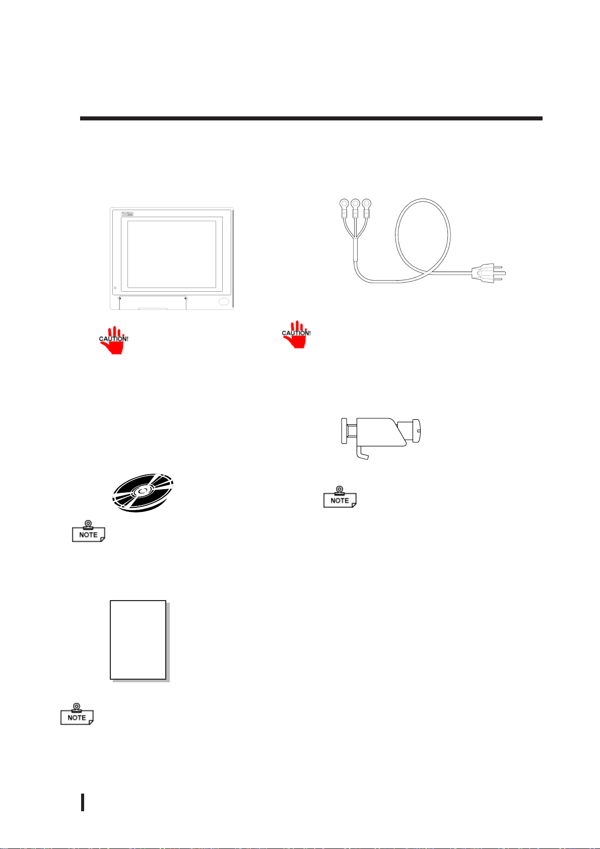
The PL package should include the following items:
PL Unit
(PL-6920/PL-6921/PL-7920/PL-7921)
Be careful when installing the PL not to damage the built-in HDD
CD-ROM (1)
(PL-X920 Series User
Manual & Driver CD)
Power Cord
This cord is designed only for AC100V use.
Any other voltage will require a different
cord.
Installation Brackets
PL-6920Series (8)
PL-7920Series (12)
For details, refer to Chapter 6 - PL Setup
Installation Guide
(English1/Japanese1)
Installation
Guide
If your PL unit contains a built-in accessory, that accessory’s Installation Guide will also
be included in the PL’s packing box. Please check that all items normally included with
that accessory are also included in this box.
12
PL-6920/PL-7920 Series User Manual

Preface
PL Series Features
The PL-6920/PL-7920 series displays are equipped with the following
features:
The Latest, High-Performance Architecture
Designed around the Pentium® III 700MHz CPU or 1GHz, the PL utilizes the type
of high performance architecture that offers you superior compatibility . Add to this
unrivalled support of the Windows® XP and other widely used operating systems.
Bright LCD with a Wide Viewing Angle
The PL’s large TFT LCD display offers excellent visibility and brightness.
Pro-face’s top of the line TFT color LCD allows you to create detailed and
powerful visual images, with excellent brightness, a wide viewing angle, and a
display capable of 64K colors.
Easy Front Panel Installation
The PL is designed to be installed easily into the front of any panel or device. It
is also rugged enough for use in harsh, industrial environments, such as those
found in the factory automation industries and provides protection equivalent
to the IP65f standard.
High Resolution, Analog-Resistance-Film Touch Panel
Standard equipment with the PL is a high resolution 1024 x 1024 touch panel,
and the mouse emulation utility provides mouse-like functionality and pointer
control.
Highly Expandable
Choose from the PL-6921/PL-7921 series unit - with 2 ISA slots, or the PL6920/PL-7920 series unit - with 4 ISA slots. In addition, the 6921/PL-7921 unit
provides a single PCI bus (slot 2), while the PL-6920/PL-7920 unit provides
two PCI buses (slots 2 and 3). Also, these slots can accommodate both Digital’s
own optional boards as well as other commercially available expansion boards.
Digital also offers a wide variety of optional products, such as a -5/-12V DC
power unit, DIM memory modules, etc.
PL-6920/PL-7920 Series User Manual
13

Preface
UL/c-UL (CSA) Application Notes
The PL6920-T4* / PL6921-T4* /PL7920-T4* /PL7921-T4* Series units are
(c)UL 1950 recognized components. (UL File No. E171486). Please pay
special attention to the following instructions when applying for UL/c-UL
(CSA) approval for machinery which includes any of these PL units.
The PL conforms as a component to the following standards:
UL 1950, Third Edition, dated March 1,1998 (Standard for Safety of Infor-
mation Technology Equipment, including Electrical Business Equipment)
CSA-C22.2 No. 950-95 (Standard for Safety of Information Technology Equip-
ment, including Electrical Business Equipment)
PL6920-T4* (UL Registration Model No.: 2780054-04)
PL6921-T4* (UL Registration Model No.: 2780054-03)
PL7920-T4* (UL Registration Model No.: 2780054-02)
PL7921-T4* (UL Registration Model No.: 2780054-01)
- Equipment with a PL mounted in it requires UL/c-UL(CSA) evaluation
for the combination of the PL and equipment.
- The PL must be used as a built-in component of an end-use product.
- Use the PL indoors only.
- When connecting the PL’s power cord, be sure to use a cord that is appro-
priate for the current and voltage used and that has conductive wires that
are 0.75 mm2 or larger.
- With an end-use product which includes the PL, be sure to place the PL’s
Power cut-off switch where the unit’s operator can easily reach it.
- Danger of explosion if backup battery is incorrectly replaced. Replaced
only with same or equivalent type recommended by the manufacturer.
Dispose of used batteries according to the manufacturer’s instructions.
- Be sure the unit the PL is built into uses a UL1950 compatible equipment
structure.
14
PL-6920/PL-7920 Series User Manual

CE Marking
The PL6920-T4* / PL6921-T4* /PL7920-T4* /PL7921-T4*units are CE
marked, EMC compliant products.
<Complies with the following Standards>
Safety
EN60950
EMI
EN55011 (Group1 Class A), EN61000-3-2, EN61000-3-3
EMS (EN61000-6-2)
EN61000-4-2, EN61000-4-3, EN61000-4-4, EN61000-4-5
EN61000-4-6, EN61000-4-8, EN61000-4-11
If following requirements are not met, the PL may fail to meet EN60950 standard
requirements.
- The PL must be used as a built-in component of an end-use product.
- Use the PL indoors only.
- When connecting the PL’s power cord, be sure to use a cord that is appropri-
ate for the current and voltage used and that has conductive wires that are
0.75 mm2 or larger.
- When installing the PL in a metal panel or cabinet, be sure to place the PL’s
Power disconnect device (cut-off switch) where the unit’s operator can easily reach it.
- There is a danger of explosion if the backup battery is incorrectly replaced.
This battery should be replaced only with same or equivalent type recommended by the manufacturer. Dispose of used batteries according to the
manufacturer’s instructions.
- Be sure the cabinet/enclosure the PL is built into uses an EN60950 approved
sheet steel structure.
Preface
PL-6920/PL-7920 Series User Manual
15

Preface
MEMO
16
PL-6920/PL-7920 Series User Manual

Overview
Chapter
1Overview
1-1 Prior To Using the PL
Prior to actual use, be sure to set up your PL as follows.
Using the PL with a Hard Disk Unit Installed
Install Hard Disk
Turn PL ON Refer to 4-2 Wiring the PL
Refer to 3-1-5 Removing/Installing HDD Unit
1-1 Prior To Using the PL
1-2 System Configuration
1-3 Options
Setup System Refer to Chapter 5 System Setup
Install the OS
Setup Preinstalled HDD
(Windows® 2000 Multi Language)
After completing the hardware setup, before any data or applications can be
placed on the drive, the OS (Windows® or MS-DOS®, etc.) must be used to initialize the HDD and create partitions. For details concerning these procedures,
refer to the OS maker’s installation manual.
The PL’s hard disk is designed for use with the Windows
Second Edition, Windows NT®4.0, Windows® 2000, Windows® XP or later OS.
The Mirror Disk unit will operate only with the Windows NT®4.0 operating system. Other operating systems do not support this driver software, etc.
Refer to 6-2-1 Setting UP HDD with no installed
OS
Refer to 6-2-2 Setting UP OS preinstalled HDD
®
95, Windows® 98
After turning the PL OFF, be sure to wait at least 5 seconds before turning ON
again. If the unit is stated within 5 seconds, it may not start up correctly.
PL-6920/PL-7920 Series User Manual
1 - 1

Overview
A
A
1 Setting Up the Touch Panel Connection
The connection method used can be via either a serial (RS-232C) or USB interface. Depending on the type of Touch Panel connection used, the OS types that can be used will
vary.
The PL unit’ s factory setting is “Serial”. When the touch panel connection method is changed
to USB, the following BIOS level System settings must also be changed.
Touch Panel Connection Compatibl e OS Type s
®
98 Second Edition
®
2000
®
XP
®
95
®
98 Second Edition
®
4.0
®
2000
®
XP
USB
Serial (RS-232C)
Windows
Windows
Windows
Windows
Windows
Windows NT
Windows
Windows
System Data Settings
For System Data Setting details, refer to Chapter 5 - System Setup
System Setting Menu Se tting Ite m USB Setting
USB Co nt roller Enabaled
Int egrat ed P eripherals
Onboard Ser ial P or t 4 Disabled
PnP/PCI Configuration
ssign IRQ For USB Enabled
Touch Panel Interface Selector Switch (T-MODE)
Set the Touch Panel I/F Selector Switch (T-MODE) to “U”. For information about the
T ouch Panel Interface (I/F) Selector Switch (T-MODE), refer to 2-4 Part Names and Fea-
tures
Mouse Emulation Software(UPDD)
When installing the Mouse Emulation Software, be sure to select USB.
2 Using the USB Interface
The PL unit's USB interface cannot be used without changing the factory settings.
When connecting peripheral devices to the USB port, change the System Settings as
shown below.
System Setup Menu Menu I te m USB Setting
Integrat ed P e riphe rals USB Cont r oller Enabled
PnP/PCI Configuration
ssign IRQ For USB Enabled
• When using a commercial-type USB hub, additional hubs cannot be
attached to the first hub. Only a single “level” USB hub can be used
when connecting USB devices.
1 - 2
PL-6920/PL-7920 Series User Manual

3 Using the LAN Interface
The PL unit's LAN interface cannot be used without changing the factory settings.
When using the LAN port, change the System Settings as shown below.
System Setup Menu Menu I te m LAN Setting
Int egrated Peripherals Onboard LA N Enabled
1-2 System Configuration
The following chart shows the range of peripheral items connected to the PL.
PL Unit
Screen P r otect ion S heet
Touch Panel
Display Unit (TFT Color)
Peripheral Dev.
Keyboard
Keyboard/Mouse
USB type Dev.
LA N Network
Printer
Peripheral Dev.
USB
1port
PS/2
1port
PS/2
USB
2 Port
10 BASE-T
100 BASE- TX
LPT
RS-232C
3 Port s
Display Module
-
- Expansion slots
- PL-6920/PL-7920:
4 ISA and 2 PCI slots
(Using 2 P CI slots reduces ISA slots to 2)
-
2 ISA and 1 PCI slot
(Using 1 P CI slot reduces I SA s l ots to 1)
Reset Button
AC IN (85V to 265V)
Main M odule
128M B P r e- installed ( standar d)
PL-6921/PL-7921:
Pow er Unit
PL-6920/
PL-7920
<4-slot type>
(Built-in)
(Built in)
IDE
Overview
Front Face FDD
*1
Unit
Exp. DI MM memor y
(64MB/128MB/256MB)
M inus Power
Supply Unit
CD-ROM Drive/
M ir r or Disk Unit
Side-mount
FDD Unit
*1
HDD/CF Car d
Expansion Slot
• This diagram shows only the PL’s internal layout and connectable devices. The user’s actual design may differ.
*1 Only one FDD unit can be used at one time, i.e. either the front panel’s FDD, or the main
unit’s FDD.
PL-6920/PL-7920 Series User Manual
(Built-in)
(Built-in)
HDD/CF Car d
Expansion Slot
Cable Connection
A ttac hed to M ain Unit
Opt ional Items
Commer c ial Items
(Purc hased by User)
1 - 3

Overview
1-3 Options
Expansion Options
Item
DIM Module
HDD Unit
Wi ndows 2000
Multi La ngua ge
Prei nstal l e d HDD
FDD Unit
-5V/-12V
Pow er Supply
CD-ROM Un it PL -DK2 00
CF Card Uni t PL -CF 200
Software
Mirroring Utility
Full-Siz ed Board
Cover
Mouse
Emulation
Software
RS-232C/RS-485
Conversi on Unit
Screen
Protection She e t
CF Ca r d GP 077-CF20
*1
*2
Mode l
number
PL-EM500
PL-EM128 SDRA M (DIMM) Provides 128MB of memory
PL-EM256
PL-HD220
PL- HD X920-
W2K/ML
PL-FD200
PL-FD210
PL-PW100
PL-SM900
PL-FC200
PL-FC210
UPDD
PL-RC500
PL-CS100
GP077-CF30 CF Card(32MB) CF Card Unit (PL-CF200) is required.
Description
SDRAM (DIMM) P r ovides 64MB of memory
SDRAM (DIMM) P r ovides 256MB of memory
20GB 2. 5" HDD Un it ( OS not included)
HDD is a 2.5 inch type unit. Capacity is 20GB. (P L unit 's C: dr ive is
already des ignat ed as 20GB. )
Preins talled OS is Windows 2000 P r ofess ional < S er vice P ack 2>.
(Sold only in combination with t he P L main unit - not s epar ately.)
Windows compatible 3.5” FDD unit ( S ide slot)
Windo ws compatible 3.5” FDD unit ( Fr ont slot - P L- 6920/PL-7920
only)
Provides -5V and - 12V power to PL expans ion slot s . Total for t wo
slots is 200mA.
IDE (A TAPI) compatible CD-ROM drive unit
(Connection cable is included with CD - ROM unit)
Designed ex clusively for 5V type cards .
Provides RA ID Level 1 protection, wit hout Mirror Disk unit .
Used when ISA full-s ized expansion boar d is us ed. (Use d only with
PL-6921/ PL- 7921<2- s lot t ype>.)
Used when ISA full-s ized expansion boar d is us ed. (Use d only with
PL-6920/ PL- 7920<4- s lot t ype>.)
This s of tware adds mous e and keyboard-like f unctionality to t he
Touch Panel.
Conv er ts an RS- 232C int erface to a RS -485 int er face. Attached to
either COM2 or COM3.
Disposa ble overlay sheets for dis play face prot ection and s tain
resis tance. Touch panel sens es Us er 's t ouch t hro ugh
sheet.(5sheets / set)
CF Card(16MB) CF Card Unit (PL-CF200) is required.
1 - 4
*1 The PL’s HDD has a fixed usage lifetime. Be sure to back up data regularly and prepare a
spare drive unit.
* 2Visit our website (http://www.pro-face.com/otasuke/) and download the mouse emula-
tion software(UPDD).
PL-6920/PL-7920 Series User Manual

Maintenance Options
Overview
Item
Mirror Disk Unit
Replacement
HDD
Installation
Fasteners
Installation
Gasket
Model
number
PL-MD200-
MD01
GP070-AT01
PL6900-WP00
PL7900-WP00
Description
Mirror Disk Unit’s replacement HDD (1).
Used to inst all t he PL int o a panel or cabinet . Same as original
equipment fasteners. (4 fasteners/ set)
Used to prevent moisture from entering into the PL’s case from
the f ront face. Same as original equipment gas ket.
PL6920- BL 00 Spa re backlight f or maintenance.
Backlight
PL7900-BL00-
Spare backlight f or maintena nce.
MS
*1 Both the PL-FD200 and the PL-FD210 cannot be used at the same time.
• When using the FDD unit with PL-6920/PL-7920 (4-slot type), either the
side mount FDD unit (PL-FD200) or the front mount FDD unit (PLFD210) is available, not simultaneously.
• The PL is equipped with three IDE interfaces, two (2) of which can be used by
the HDD unit, and one (1) which can be used by either the CD-ROM drive
unit. Physically, even though up to thr ee (3) IDE drive units can be connected
at the same time, IDE interface specifications require that a controller's simultaneous operation be limited to a single master and slave unit, for a total of two
devices.
The following chart shows the combinations available when using two IDE units.
HDD Unit
CD-ROM Dr ive
Unit
CF Card Unit
MS: Combination of 2 units - Master or Slave
M: Used onl y for Master.
S: Used only for Slave.
MS M M S
SS
SMMMS
PL-6920/PL-7920 Series User Manual
1 - 5

Overview
The PL-6920 and PL-7920 Series units can all use commercially available expansion boards
(PCI/ISA compatible) as well as a standard keyboard, mouse,printer, etc. When using a
USB cable, the PL-6920 and PL-7920 Series units can also use USB compatible devices.
However, among the commercially available USB devices, not all will be compatible with
the PL unit.
• Since the PL unit's hard disk drive (HDD) is a consumable item,
i.e. it has a limited lifetime, be sure to back up its data regularly
and prepare a spare HDD unit.
• The Hard Disk lifetime given here may be reduced due to unforeseen environmental factors, however, generally speaking, at an
operating temperature of 20oC the disk should last for 20,000
hours (of operation) or approximately 5 years, whichever comes
first.
Commercially Available Items
• Since the PL expansion slots do not supply DC-5V and DC-12V current. To use
expansion boards requiring DC-5V or DC-12 V, the optional PL-PW100 power
supply should be installed.
• Be sure to use only DIM modules manufactured by Digital. Installing
other DIM modules may result in either damage to or failure of the PL,
and will void your warranty.
• When using USB type devices, be sure they are USB compatible, and be
sure to read that device's installation guide prior to connecting it to the
PL.
1 - 6
PL-6920/PL-7920 Series User Manual
Specifications
Chapter
2-1 General Specifications
2-2 Performance Specifications
2-3 Interface Specifications
2Specifications
2-1 General Specifications
1 Electrical Specifications
2-4 PL External Features
2-5 PL Dimensions
Rated Voltage
Rated Voltage Range
Rated Frequency
Allowable Pause
Duration
Power Consumption
Voltage Endurance
Insulation
Resistance
PL-6920/PL-7920
(4-slot type)
AC 100V to AC 240V
AC 85V to AC 265V
50/60Hz
shorter than 1 cycle
(however, pause occurrences must be more than 1 second apart)
150VA or less 120VA or less
AC 1500V at 20mA for 1 minute
(between the live wire and the grounding (FG) terminal)
Greater than 10MΩ at DC 500V
(between the live wire and the grounding (FG) terminal)
PL-6921/PL-7921
(2-slot type)
PL-6920/PL-7920 Series User Manual
2 - 1

Specifications
(
)
(
)
2 Environment Specifications
PL692*-T41
(CPU:700MHz)
PL792*-T41
(CPU:700MHz)
Ambient Operating
Temperature
PL692*-T42
(CPU:1GHz)
PL792*-T42
(CPU:1GHz)
Ambient Storage Temperature
Amb ient Humidity
(Operat ing and Storage)
Dust Level
o
-10
C to +60 oC
10% RH to 85% RH (no condensation)
Fre e of dust
Pollution Level Pollution Level 2
Maximum wet bulb temperature
Operating Atmosphere
Vibratio n Endurance
Noise Endurance
(Impulse Noise)
o
29
C
Free of corrosive gas
2
19.6m/s
(4.9m/s
: 10 to 25Hz applied in X, Y, and Z directions for 30 minutes each
2
when us ing HDD unit, 9.8m/s2 when using FDD)
Noise Voltage: 1500V(via noise simulator)
Pulse Duration: 50ns, 500ns, 1µs
Rise Time: 1ns
Noise Immunity
(Fi rst t ransient burst noise)
Electrostatic Discharge Immunity
Power Line: 2kV IEC 61000-4-4
COM Port: 1kV IEC 61000-4-4
4kV IE C 61000-4-2
Not using fan
Cabinet
Interior
Panel face
Not using fan
Cabinet
Interior
Panel face
Usi ng Fan
Usi ng Fan
Not using fan* 1
o
C to 40 o C
5
Usi ng Fan
Usi ng Fan
Not using fan* 1
o
C to 40 o C
5
5 o C to 50 o C
(With HDD attached)
*1
o
5
C to 40 o C
(With HDD attached)
o
5
C to 50 o C
With HDD attached
o
5
C to 40 o C
(With HDD attached)
o
C to 45 o C
5
(With HDD attached)
*1
Must use fan
o
5
C to 45 o C
With HDD attached
Must use fan
*1 When the PL’s internal electric fan is removed.
• When using any of the PL’s optional devices, be sure to check that device’s specifications for any special conditions or cautions that may apply to its use.
• When using a full sized expansion board, be sure to check its dimensions and shape,
since they will affect the board’s environment specifications, such for vibration, etc.
• Be aware that not only does the Hard Disk have a fixed lifetime, but that accidents
can always occur. Therefore, be sur e to back up your Hard Disk’s data regularly, or
prepare another Hard Disk unit that can be used for backup.
• The Hard Disk lifetime given here may be reduced due to unforeseen environmental
factors, however , generally speaking, at an operating temperature of 20
o
C the disk should
last for 20,000 hours (of operation) or approximately 5 years, whichever comes first.
• Using the Hard Disk in an environment that is excessively hot and/or humid will
shorten the disk’s usage lifetime. A maximum wet bulb temperature of 29
o
C is rec-
ommended. This is equivalent to the following data.
2 - 2
PL-6920/PL-7920 Series User Manual

Temperature Humidity
at 35oC no higher t han 6 4% R H
o
at 40
C no higher t han 4 4% R H
3 Dimensions
Grounding*1
Rating*2
Cooling
Method
Weigh t (with HDD and
External Dimensions
(excluding projections)
Dimensions Includ ing
Full- s ized Cover
(excluding projections)
Dimensions Includ ing
RS-232C/RS-485
Conver sion Unit
(excluding cable &
projections)
700MHz CPU
Model
1GHz CPU
Model
Specifications
PL-6920 Series PL-7920 Series
PL-6920 PL-6921 PL-7920 PL-7921
Exclusive grounding only. Less than 100Ω , or your country’s applicable
Equivalent to IP65f (JEM1030)
Via heat convection tubes and electric fan
Via both heat convection tubes built in to CPU fan and electric fan
Less than 9.5 kg Less than 8.5 kg Less than 10.5 kg Less than 9.5 kg
W346×H287×
D170mm
W393×H287×
D170mm
W346×H287×
D170mm
W346×H287×
D123mm
W393×H287×
D123mm
W346×H287×
D145mm
W374×H325×
D180mm
W422×H325×
D180mm
W374×H325×
D180mm
W374×H325×
D134mm
W422×H325×
D134mm
W374×H325×
D156mm
*1 4-2-3 Grounding Cautions.
*2 The front face of the PL unit, installed in a solid panel, has been tested using conditions
equivalent to the standard shown in the specification . Even though the PL unit’s level of
resistance is equivalent to the standard, oils that should have no effect on the PL can
possibly harm the unit. This can occur in areas where either vaporized oils are present, or
where low viscosity cutting oils are allowed to adhere to the unit for long periods of time. If
the PL’s front face protection sheet becomes peeled off, these conditions can lead to the
ingress of oil into the PL and separate protection measures are suggested. Also, if nonapproved oils are present, it may cause deformation or corrosion of the front panel’s
plastic cover. Therefore, prior to installing the PL be sure to confirm the type of conditions
that will be present in the PL’s operating environment.
If the installation gasket is used for a long period of time, or if the unit and its gasket are
removed from the panel, the original level of the protection cannot be guaranteed. To
maintain the original protection level, you need to replace the installation gasket regularly.
PL-6920/PL-7920 Series User Manual
2 - 3

Specifications
2-2 Performance Specifications
1 Performance Specifications
CPU
DRAM(SDRAM DIMM)
BIOS
Secon dary Cache
Memory
Graphics
Video Memory
Type
Touch
Panel
Interfaces
Resolution
Interface
Serial
Printer
Keyboard
Mouse
RA S
Disk I/F
*2
USB
*2
LAN
Pentium III (700MHz / 1GHz)
Equipped with 128MB (2 DIMM sockets – max. of 512MB)
AWARD PC/AT Compa tible
25 6KB (built-in)
PL-6920 Series SVGA (800 x 600 dots)
PL-7920 Series XGA (1024×768 dots)
VESA 16 colors/256 colors/64K colors
UMA type
Resistive Film (Analog)
1024×1024
COM4
USB
RS-232C
(w/FIFO)
Com plies with Centronics Standards (ECP/SPP/EPP equivalent) D-Sub 25 pin, female
PS/2 Interface (mini DIN 6 pin, female) front 1port / side 1port
PS/2 Interface (mini DIN 6 pin, female) side 1port
RAS Interface (D-sub 25 pin, male)
FDD Unit
IDE I/F
USB 1.1 com patible front 1port / side 2ports
Satisfies IEEE802.3 standard (auto change to 10BASE-T/100BASE-TX)
When the Mouse Emulation Software (UPDD) is installed, either the
Serial (COM4) interface or the USB interface must be selected.
COM1 D-Sub 9 pin male
COM2 D-Sub 9 pin male (RI/+5V switch poss.)
COM3 D-Sub 9 pin male (RI/+5V switch poss.)
Side Access/ 2 modes/ 3.5” FD
Front Access/ 2 modes/ 3.5” FD
(Available for only PL-6920/PL-7920<4-slot type>)
2.5” HDD I/F
CD-ROM drive unit (PL-DK200)
*1
*1 If the PL unit’s OS is Windows® 95 or W indowsNT® 4.0, only the Serial interface can be used.
*2 BIOS setting must be changed.
2 Display Functions
Display Type
Pixel Density
Dot Pitch
Effective DisplayArea
Display Colors
Backlight’s Life span
Backlight
Contrast Con trol
The PL’s backlight should be replaced by only an authorized repairman. For infor mation about this service, please contact your nearest authorized distributor.
2 - 4
64K colors
More than 50,000 hours at an ambient temperature of 25
CFL (Replaceable)
Not P ossible
5.2.5 Integrated Peripherals
PL-6920 Series PL-7920 Series
TFT Color LCD(12 inchi) TFT Color LCD(15 inchi)
800 x 600 pixels 1024 x 768 pixels
0.3075×0.3075mm 0.297×0.297mm
W246.0 x H184.5 mm W304.1 x H228.1mm
o
C. (Until the
PL-6920/PL-7920 Series User Manual

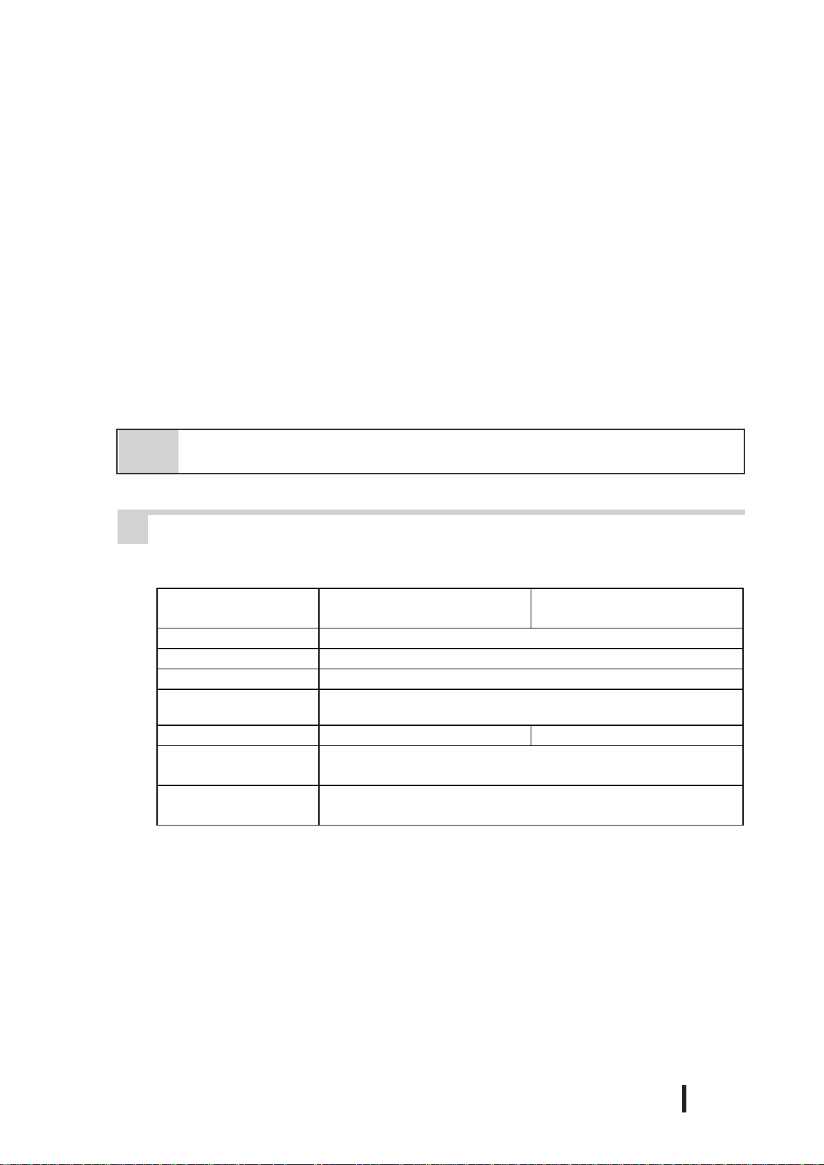
3 Expansion Slots
Specifications
st
1
slot
nd
2
slot
rd
3
slot
th
4
slot
Power
Supply
CPU
700MHz
Model
CPU
1GHz
Model
PL6920/792
0
(4-slot
type)
ISA ISA 163 x 122 mm 163 x 122 mm 20 mm
PCI PCI 250 x 122 mm
ISA ISA 338 x 122 mm
PCI/ISA No ne 250 x 122 mm 338 x 122 mm 25 mm
ISA None 250 x 122 mm 338 x 122 mm 20 mm
5V:4A,
12V:1A
(total for
4 slots)
5V:3.5A,
12V:1A
(total for
4 slots)
PL6921/792
1
(2-slot
type)
5V:2A,
12V:0.5A
(total for
2 slots)
5V:1A,
12V:0.5A
(total for
2 slots)
Without the
Full- s ized
cover
250 x 122 mm 25 mm
Board Size
With the
Full- s ized
cover
Slot
Pitch
Actual
Thickness of
Expansion
Board
Less than
13 mm
Less than
18 mm
Less than
18 mm
Less than
13 mm
• For the 2nd and 3rd slots on the PL-6920/PL-7920<4-slot type>, and the 2nd slot
on the PL-6921/PL-7921<2-slot type>, either the PCI or the ISA type can be used.
Pins 1, 4, 16 and 17 will become O.D when the SPP mode specification is used. If
the mode changes to ECP or EPP, these pins will become T.S
4 Clock(RTC) Accuracy
The PL’s built-in clock (RTC) may have a slight error. With the ambient temperature
mentioned in the specification with no power flow, the allowance is +180 seconds
per month, however, the allowance may vary and could be up to +300 seconds per
month depending on the ambient temperature difference or how old the unit is. If the
clock accuracy is essential for the system, you need to adjust the clock regularly.
Clock(RTC) accuracy +180 seconds per month
PL-6920/PL-7920 Series User Manual
2 - 5

Specifications
2-3 Interface Specifications
If the optional board (that connects to the extended slot (ISA/PCI) has a current
consumption value equal to the specified upper limit value (described in “2.2.3 Expansion Slots”, ensure that the I/O device’s total 5V curr ent consumption value conforms to the following standard:
External I/O Device's Total
Current consum ption*1
PLX920T-41
(CPU:700MHz)
4-slot ty pe
1.5A 1.0A 0.5A 0.5A
PLX921T-41
(CPU:700MHz)
2-slot ty pe
*1 Indicates the total current value being supplied from RS-232C I/F (COM2/COM3), RAS I/F,
USB I/F and Mouse I/F’s +5V terminal.
1 Printer Interface (LPT1)
D-sub 25 Pin (Female)
13 12 11 10 9 8 7 6 5 4 3 2 1
25 24 23 22 21 20 19 18 17 16 15 14
Screw Size: (4-40): Inch Type
PLX920T-42
(CPU:1GHz)
4-slot ty pe
PLX921T-42
(CPU:1GHz)
2-slot ty pe
2 - 6
Pin
SPP/ECP Mode
No.
Signal Name
*1
1
2 DATA0 DATA0
3 DATA1 DATA1
4 DATA2 DATA2
5 DATA3 DATA3
6 DATA4 DATA4
7 DATA5 DATA5
8 DATA6 DATA6
9 DATA7 DATA7
10 ACKNLG ACKNLG Input TTL 23 GND GND
11 BUSY WAIT Input TTL 24 GND GND
12 PE PE Input TTL 25 GND GND
13 SLCT SLCT Input TTL
STRB WRITE
EPP Mode
Signal Name
Direction
In/Output
In/Output
In/Output
In/Output
In/Output
In/Output
In/Output
In/Output
In/Output
Electrical
Specif.
O.D/T.S 14
T.S 15 ERROR ERROR Input TTL
T.S 16
T.S 17
T.S 18 GND GND
T.S 19 GND GND
T.S 20 GND GND
T.S 21 GND GND
T.S 22 GND GND
Pin
SPP/ECP Mode
No.
*1
*1
*1
EPP Mode
Signal Name
AUTOFD DSTRB
INIT INIT
SLCTIN ADSTRB
Signal Name
• Pins 1, 4, 16 and 17 will become O.D when the SPP mode specification is
used. If the mode changes to ECP or EPP, these pins will become T.S
PL-6920/PL-7920 Series User Manual
Direction
In/Output
In/Output
In/Output
Electrical
Specif.
O.D/T.S
O.D/T.S
O.D/T.S

2 Keyboard Interface
Mini - DIN 6 pin (Female)
6
4
2
1
5
3
(The PL’s front and side
connectors are the same)
3 Mouse Interface
Mini - DIN 6 pin (Female)
6
4
2
1
5
3
Specifications
Pin No. Sign a l Name
1 KEY DATA
2NC
3GND
4+5V
5 KEY CLK
6NC
SHIELD GND
Pin No. Signal Name
1 Mouse DATA
2 NC
3 GND
4 +5V
5 Mouse CLK
6 NC
SHIELD GND
PL-6920/PL-7920 Series User Manual
2 - 7

Specifications
4 RS-232C Interface (COM1/COM2/COM3)
Dsub 9 pin (Male)
4321
5
9876
Screw Size: (4-40): Inch Type
Pin No. Signal Name Pin No. Signal Name
1 CD 6 DSR
2 RXD 7 RTS
3 TXD 8 CTS
4 DTR 9 RI
5 GND
*1 COM2 and COM3 can perform RI/+5V changeover
/+5V
The No. 5 pin is the signal ground. Be sure to connect it with the other unit’s SG
(Signal Ground) pin.
Number 9 pin’s [RI/+5V] changeover is COM2 and COM3. COM1 becomes [RI].
To set the changeover for COM2 and COM3, remove the PL’s rear maintenance
cover and use the main function switches, next to the PL’s circuit board. To change
COM2, set main function switch SW2 to ON, and COM2 will change to +5V. The
factory setting is OFF and [RI]. To change COM3, simply turn SW3 to ON.
3-1-1 Removing the Rear Maintenance Cover
2 - 8
Main Function Switch
PL-6920/PL-7920<4-slot type>
(rear maintenance cover removed)
• SW1 and SW4 are reserved. Do not change the factory settings.
• Be sure to confirm the interface specifications of the device you are connecting to
prior to changing these settings. An incorrect setting could cause a unit malfunction or accident.
• Be sure to change these settings only after confirming that the PL ’ s power supply
is turned OFF. Failure to do so could cause a unit malfunction.
PL-6920/PL-7920 Series User Manual

5 RAS Interface
)
D-Sub 25 pin (Male)
1 2 3 4 5 6 7 8 9 10111213
14 15 16 17 18 19 20 21 22 23 24 25
Screw Size: (4-40): Inch Type
Pin No. Signal Name Pin No. Signal Name
1GND14GND
2+5V
(max. 100mA)
3 +12V
(max. 100mA)
4NC17NC
5 RESET INPUT (+) 18 NC
6 DIN 0 (+) 19 NC
7DOUT (-)20 NC
8 DOUT (+) 21 LAMP OUT (-)
9 ALARM OUT (-) 22 LAMP OUT (+)
10 ALARM OUT (+) 23 NC
11 RESET INPUT (-) 24 DIN1 (-)
12 DIN 0 (-) 25 NC
13 DIN 1 (+)
Specifications
15 +5V
16 NC
Be sure to use only the rated voltage level when using the No. 2 [+5V] and No. 3[12V]
for external power output. Failure to do so can lead to a unit malfunction or accident.
For RAS feature details, see Appendix 2 RAS Feature
External Input Signal (Dual use of DIN, Remote Set Input Port)
Input Voltage DC12V to DC24V
Input Current
Operating Voltage ON voltage: 9V (min), OFF voltage:3V (max
7mA
Isolation Method Via photocoupler
(Interface Circuit) (Connection Example)
R
+5V
PC357
1.8kΩ
1/10W
Reset Input(+)pin 5
R
(DC12 to DC24V)
Reset Input(-)pin 11
1.8kΩ
1/10W
DIN0(+)pin 6
DIN1(+)pin 13
Cable
DIN0(-)pin 12
DIN1(-)pin 24
D-sub 25 pin Connector
No polarity - for Sink/
Source input
DC12V to
DC24V
switch or switching
device
• General Purpose Input (DIN) level must be 1.5S or longer to be detected.
• Be sure the voltage value between terminals is controlled via the input voltage,
so that the PL is operated within its recommended range. If the input voltage
exceeds this range, a malfunction or PL damage may occur.
PL-6920/PL-7920 Series User Manual
2 - 9

Specifications
g
)
• With Sink/Source input, even if the D(-), and RESET(-) are positive, and
D(+), RESET(+) are negative, no problems are created. Be sure to operate
the unit within the recommended voltage range.
External Output Signal (DOUT, Alarm Output, Lamp Output Port)
Rated Load Voltage DC12V to DC24V
Maximum Load Current
Maximum Volta
Isolation Method Via photocoupler
(Interface Circuit) (Connection Example)
R
+5V
100mA/point
e Drop between Terminal s 1.5V (at 100mA l oad current
DOUT(+)pin 8
Alarm Output(+)pin 10
Lamp Output(+)pin 22
Load
*1
PC357
SSTA06
4.7kΩ
Alarm Output(-)pin 9
Lamp Output(-)pin 21
Cable
DOUT(-)pin 7
D-sub 25 pin Connector
DC24V
• Be sure to operate the unit within its maximum load current. If the maxi-
mum load current exceeds this range, a malfunction or PL damage may
occur.
• Design your electrical system by adding the load current and voltage values to
the terminal voltage. If load current value used is large, a maximum voltage of
1.5V will exist between the terminals.
• When connecting an induction load, be sure to connect the above drawing's
protection diode(*1).
2 - 10
6 USB Interface
Receptacle
4321
Pin No. Name
1
2
3
4
Vcc
- Data
+ Data
GND
PL-6920/PL-7920 Series User Manual
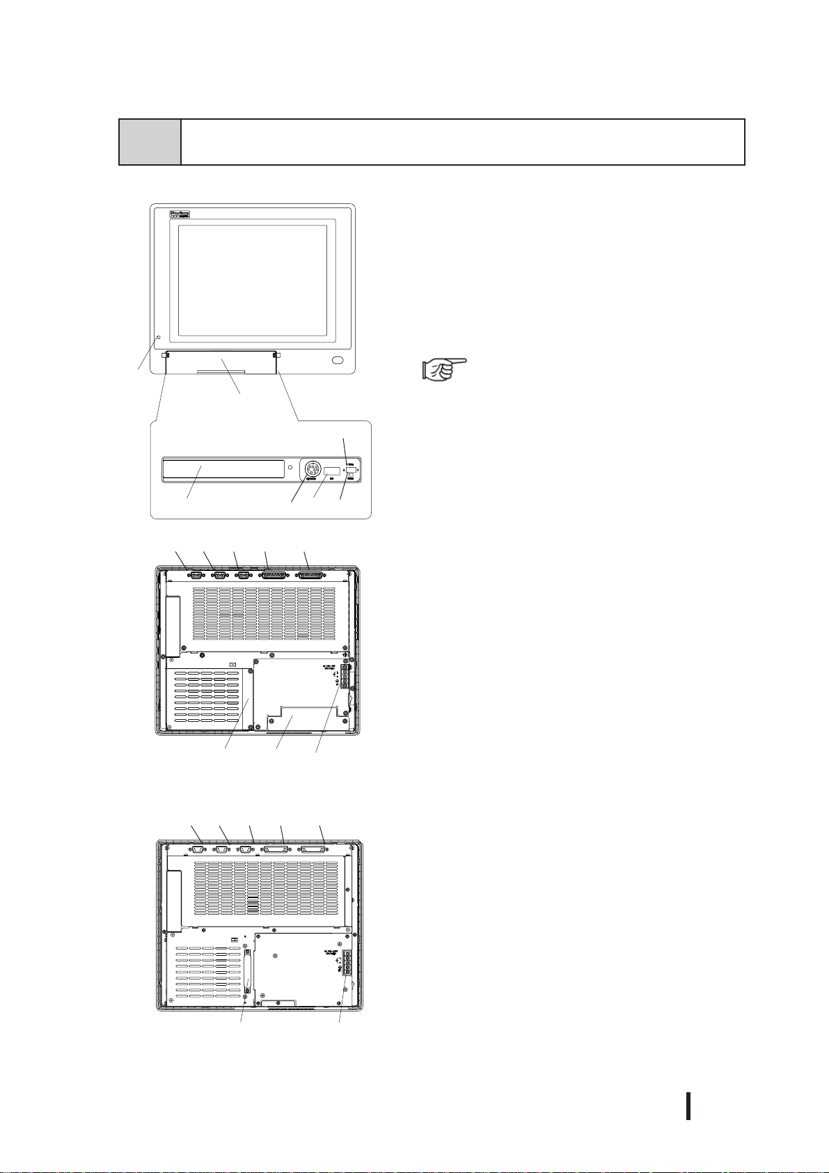
2-4 Part Names and Features
The following explanation uses the PL-6920 Series unit.
A:Display Area/T ouch Panel
Display output area. The built-in SVGA or XGA
controller supports PC compatible architecture.
B:Power Lamp LED/RAS Status Lamp
A
B
C
<
I
nside front maintenance cover>
D
NOD
PL-6920(4-slot type)
N O
PL-6921(2-slot type)
G
E
H
F
MIJ KL
MIJ KL
This LED indicates both the RAS monitor feature’ s
status and the PL’s power status. The status of the
lamp changes according to the alarm type detected
by the RAS feature.
A-2 RAS Feature
C:Front Maintenance Cover
Open this cover to connect the optional FDD unit.
D:Front Mount FDD Slot
Slot for installing the FDD unit (PL-FD200).
(only PL-6920/PL-7920<4-slot type>)
E:Keyboard Connector (KEYBOARD)
A PS/2 compatible keyboard is connected here.
F:USB Connector (USB)
USB 1.1 compatible devices can be connected here.
G:T ouch Panel Interface Selector Switch (T-MODE)
U-Touch data uses the USB I/F(USB)
S-Touch data uses the serial I/F(COM4)
H:Hardware Reset Switch (RESET)
I:RS-232C Connector (COM1)
J:RS-232C Connector (COM2 - RI/+5V changeover)
K:RS-232C Connector (COM3 - RI/+5V changeover)
These RS-232C interfaces (D-sub 9 pin male connectors), allow communication with other computers and connection to peripheral devices.
L:Printer Connector (LPT1)
Centronics standard interface (D-sub 25 pin female
connector), which connects a parallel device, such
as a printer (supports ECP/SPP/EPP).
M:RAS Connector (RAS)
Interface for DIN, DOUT, Watchdog, and Remote
Reset. (D-sub 25 pin male connector)
N:IDE I/F Cover
To connect the optional CD-ROM drive unit (PLDK200), remove this cover and use this connector.
O:Power T erminals
Connect the AC100V/AC240V power terminals here.
Specifications
PL-6920/PL-7920 Series User Manual
2 - 11

Specifications
E
P
F
Q
R
PL-6920(4-slot type)
U
P:Mouse Connector
A PS/2 compatible mouse is connected here.
Q:LAN Connector (10/100BASE-T)
S
Network Interface (meets IEEE802.3 standard /
10BASE-T/100BASE-TX autochangeover).
R:Side Mount FDD Slot
T
Houses the FDD unit.
S:Expansion Slots
T:HDD/CF Card Expansion Unit Slots
Houses an additional HDD unit, or CF Card
Expansion unit.
U:Half Cover
When an optional DIM module or expansion board
is used here, this cover is removed.
V:Power Switch
Use this switch to turn the PL’s power ON or OFF .
W:Rear Maintenance Cover
Remove this cover to install the optional DIM
module, or an expansion board.
V
PL-6920(4-slot type)
PL-6920(4-slot type)
W
2 - 12
PL-6920/PL-7920 Series User Manual

2-5 PL Dimensions
1 General Dimensions
PL-6920
330[12.99]
Specifications
(Unit: mm/in. - excluding projections)
Top View
346[13.62]
Front View
13[0.51]
287[11.30]
170[6.69]
271[10.67]
Side View
PL-6920/PL-7920 Series User Manual
2 - 13

Specifications
PL-6921
330[12.99]
Top View
346[13.62]
123[4.84]
13[0.51]
Front View
287[11.30]
271[10.67]
Side View
2 - 14
PL-6920/PL-7920 Series User Manual

PL-7920
Specifications
(Unit: mm/in. - excluding projections)
359[14.13]
Top View
374[14.72]
Front View
13[0.51]
325[12.80]
180[7.09]
310[12.20]
Side View
PL-6920/PL-7920 Series User Manual
2 - 15

Specifications
PL-7921
(Unit: mm/in. - excluding projections)
359[14.13]
Top View
374[14.72]
Front View
13[0.51]
325[12.80]
134[5.27]
310[12.20]
Side View
2 - 16
PL-6920/PL-7920 Series User Manual

Specifications
2 External Dimensions (with Installation Fasteners installed)
PL-6920
342[13.46]
330[12.99]
165[6.50]
236[9.29]
352[13.86]
170[6.69]
346[13.62]
13[0.51]
8[0.31]
293[11.54]
287[11.30]
10[0.39]
264[10.39]
5[0.20]
271[10.67]
135.5[5.33]
283[11.14]
PL-6920/PL-7920 Series User Manual
2 - 17

Specifications
PL-6921
342[13.46]
330[12.99]
236[9.29]
165[6.50]
352[13.86]
8[0.31]
293[11.54]
346[13.62]
287[11.30]
10[0.39]
264[10.39]
13[0.51]
123[4.84]
5[0.20]
271[10.67]
135.5[5.33]
283[11.14]
2 - 18
PL-6920/PL-7920 Series User Manual

PL-7920
Specifications
371[14.61]
359[14.13]
264[10.39]
26[1.02]
108[4.25] 120[4.72]
332[13.07]
325[12.80]
11[0.43]
381[15.0]
374[14.72]
179.5[7.07]
13[0.51]
180[7.09]
24[0.94]
120[4.72]
108[4.25]
310[12.20]
155[6.10]
322[12.68]
30[1.18]
142[5.59]
PL-6920/PL-7920 Series User Manual
147[5.79]
2 - 19

Specifications
26[1.02]
108[4.25] 120[4.72]
PL-7921
325[12.80]
332[13.07]
371[14.61]
359[14.13]
264[10.39]
11[0.43]
381[15.0]
374[14.72]
179.5[7.07]
13[0.51]
134[5.28]
24[0.94]
120[4.72]
108[4.25]
310[12.20]
155[6.10]
322[12.68]
2 - 20
30[1.18]
142[5.59]
147[5.79]
PL-6920/PL-7920 Series User Manual

Specifications
3
PL and RS-232C/RS-485 Conversion Unit (PL-RC500) Dimensions
(Unit: mm/in. - excluding projections)
PL-6920
330[12.99]
Top View
346[13.62] 13[0.51]
170[6.69]
Front View
60[2.36]
271[10.67]
287[11.30]
55[2.17]
Side View
31[1.22]
90[3.54]
PL-6920/PL-7920 Series User Manual
2 - 21

Specifications
PL-6921
(Unit: mm/in. - excluding projections)
330.0[12.99]
Top View
346[13.62]
Front View
13[0.51]
287[11.30]
123[4.84]
145[5.71]
Side View
271[10.67]
55[2.17]
31[1.22]
2 - 22
60[2.36]
90[3.54]
PL-6920/PL-7920 Series User Manual

PL-7920
359[14.13]
Top View
374[14.72]
Specifications
(Unit: mm/in. - excluding projections)
180[7.09]
13[0.51]
Front View
60[2.36]
120[4.72]
325[12.80]
Side View
310[12.20]
55[2.17]
31[1.22]
PL-6920/PL-7920 Series User Manual
2 - 23

Specifications
PL-7921
(Unit: mm/in. - excluding projections)
359[14.13]
Top View
374[14.72]
Front View
60[2.36]
120[4.72]
13[0.51]
325[12.80]
134[5.27]
156[6.14]
Side View
310[12.20]
55[2.17]
31[1.22]
2 - 24
PL-6920/PL-7920 Series User Manual

Specifications
4 Full Sized Cover Attachment Dimensions
PL-6920 Series
The following explanation uses the PL-6921 unit.
10[0.39]
PL-7920 Series
310[12.20]
Top View
65[2.56]
(Unit: mm/in.)
(PL-6921)
The following explanation uses the PL-7920 unit.
310[12.20]
39[1.53]
Top View
(PL-7920)
66[2.60]
PL-6920/PL-7920 Series User Manual
2 - 25

Specifications
• Prior to installing a full-sized board and the PL’s full-sized cover (PL-FC200/
• When using a full sized expansion board, be sure to check its dimensions and
• There are two types of full-sized covers - one for 4-slot units (PL-6920/7920) and
PL-FC210), be sure that the PL is installed in its attachment panel/cabinet.
Due to dimension differences, a full sized expansion board and PL’s full-sized
cover can not be attached prior to installing the PL into a panel.
shape, since they will affect the board’s environment specifications, such as
for vibration, etc.
one for 2-slot units (PL-6921/7921).
2-slot type PL-FC200
4-slot type PL-FC210
1.3 Optional Items
5 Panel Cut Dimensions
PL-6920 Series
less than
4-R3[0.12]
+0.02
0
[10.71 ]
+0.5
0
272.0
331.0
+0.5
[13.03 ]
0
+0.02
0
(Unit: mm/in.)
2 - 26
PL-6920/PL-7920 Series User Manual

PL-7920 Series
less than
4-R3[0.12]
+0.02
0
[12.24 ]
+0.5
0
311.0
Specifications
(Unit: mm/in.)
360.0
+0.5
[14.17 ]
0
+0.02
0
• Be sure the thickness of the installation panel is from 1.6 to 10 mm.
• All panel surfaces used should be strengthened. Especially, if high levels of
vibration are expected and the PL’s installation surface (i.e. an operation
panel’s door, etc.) can move (i.e.open or close) due consideration should be
given to the PL’s weight.
• To insure that the PL’s water resistance is maintained, be sure to install the PL
into a panel that is flat and free of scratches or dents.
• Be sure all installation tolerances are maintained to prevent the unit from
falling out of its installation panel.
PL-6920/PL-7920 Series User Manual
2 - 27

Specifications
6 Installation Fasteners
(Unit: mm/in.)
16[0.63]
11[0.43]
31[1.22]
M5
19.5[0.77]
10[0.39]
2 - 28
PL-6920/PL-7920 Series User Manual

Installing Optional Units and Expansion Boards
Chapter
3-1 Installing Options and Expansion Boards
3Installing Optional
Units and Expansion Boards
The User can install a variety of optional units and expansion boards made by Digital in the
PL, as well as a number of commercially available ISA-bus compatible boards. This chapter describes both the products that can be installed in the PL and how to install them.
3-1
T o avoid electric hazards, be sure to turn the PL’s power OFF before installing
any optional units or expansion boards.
Installing Options and Expansion Boards
The following explanation pages describe the installation and removal procedures for the
PL’s DIM module (PL-EM500/PL-EM128), FDD unit (PL-FD200/PL-FD210), HDD unit
(PL-HD220/PL-HDX920-W2K/ML), expansion boards, and the CD-ROM drive unit (PLDK200) and the electric FAN Unit.
For information about the installation of other option units, please refer to those unit’s
individual [Installation Guide].
WARNING
Use a screw driver to loosen or tighten the screws. Be careful not to over-tighten
any screws, since it may damage the equipment.
Be careful when removing or inserting any screws inside the body of the PL.
PL-6920/PL-7920 Series User Manual
3 - 1
Installing Optional Units and Expansion Boards
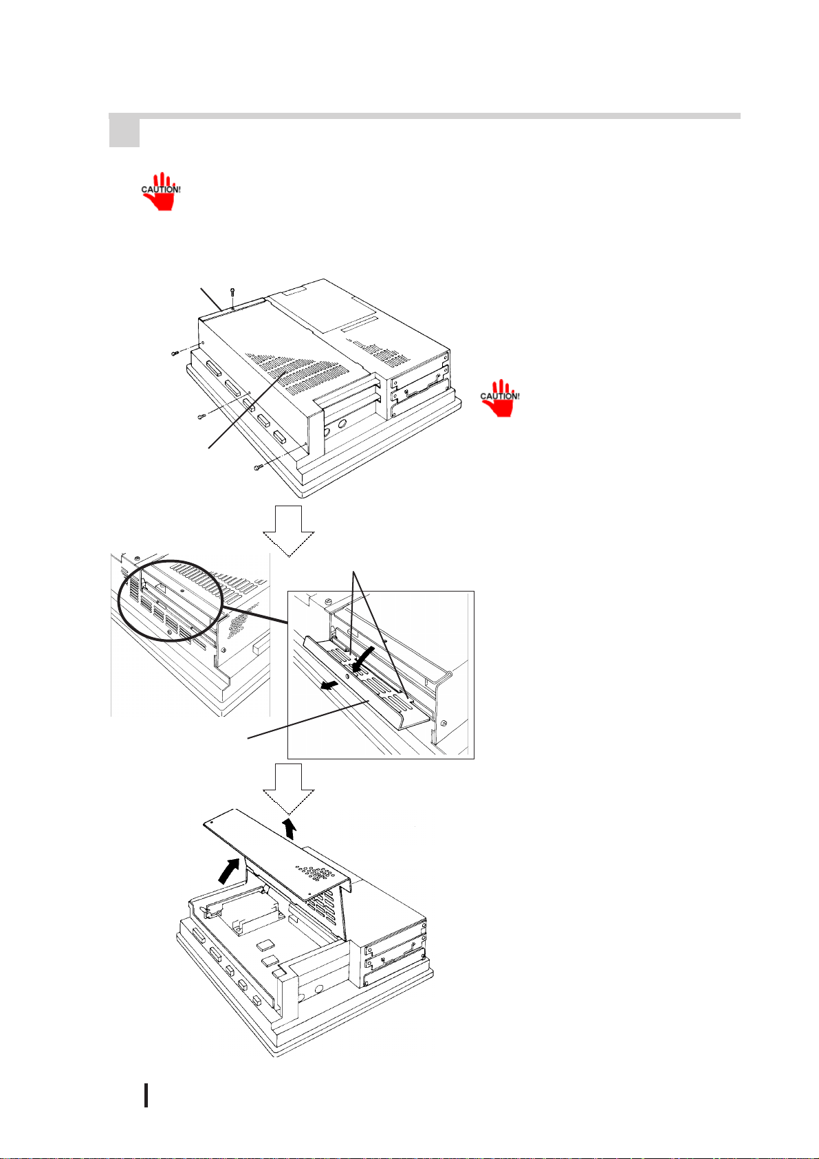
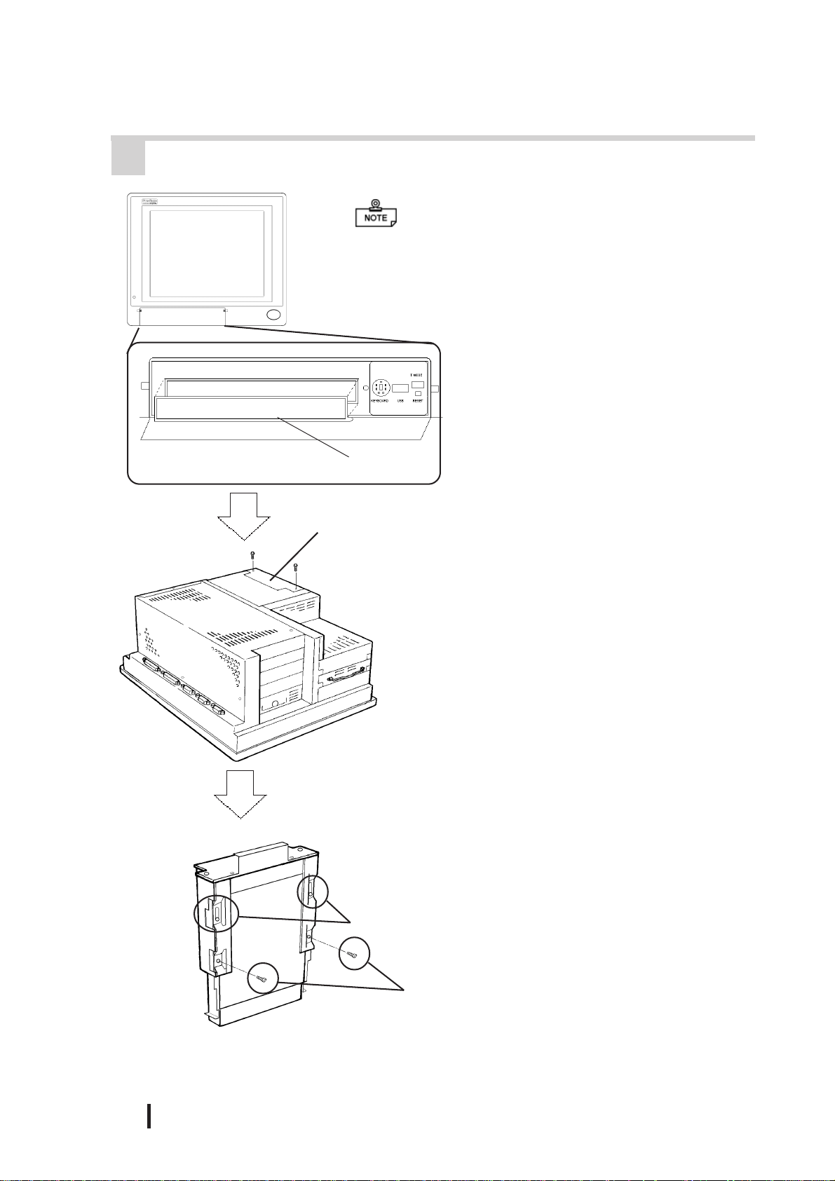
1 Removing the Rear Maintenance Cover
Handle the rear maintenance cover with care, since it is made of aluminum and
is easily bent.
PL-6921/PL-7921 (2 slot type)
Half Cover
Rear Maintenance
Cover
Guide Tabs
1) Unscrew the four attachment screws
used to hold the rear maintenance
cover and half-cover in place.
Remove the half cover, and
then the rear maintenance
cover.
2) Pivot the half cover open and lift
up slightly to free the guide tabs.
Next, remove the half-cover.
3 - 2
Half Cover
3) Remove the rear maintenance cover .
PL-6920/PL-7920 Series User Manual

PL-6920/PL-7920 (4 slot type)
Half Cover
Rear Maintenance
Cover
Installing Optional Units and Expansion Boards
1) Unscrew the attachment screws used
to hold the rear maintenance
cover(4) and half cover(1) in place.
Remove the rear maintenance cover, and then the
half cover.
Guide Tabs
2) Remove the rear maintenance cover.
3) Pivot the half cover open and lift
up slightly to free the guide tabs.
Next, remove the half cover.
Half Cover
PL-6920/PL-7920 Series User Manual
3 - 3

Installing Optional Units and Expansion Boards
2 Installing the DIM Module
• Since DIM module sockets are easy to break, be sur e to install the DIM module
very carefully.
• Do not change the factory installed DIM module’s socket position.
The PL comes with a single, 128MB DIM module pre-installed. There is one more
empty socket that can be used and the procedures that follow describe how to install
a DIM module in that empty socket.
Empty Socket
1) Replace the rear maintenance
2) Install the DIM module for expan-
(PL-EM500 / PL-EM128/ PL-EM256)
cover and the half cover.
3-1-1 Removing the rear maintenance cover
sion on the empty socket.
Built-in DIM Module
Foolproof
Positioning grooves
Foolproof
Positioning pins
3) Adjust the foolproof positioning
grooves so that they align with the
foolproof positioning pins.
4) Insert the DIM module into the
DIM module socket.
3 - 4
PL-6920/PL-7920 Series User Manual

Installing Optional Units and Expansion Boards
5) Push the DIM module down until
the side stoppers lock.
6) Replace the rear maintenance
cover and the half cover and secure
them in place with the attachment
screws.
To Remove the DIM Module
When removing the module from the socket, press down on the socket’s ejector
tabs to release the module.
3 Installing the FDD Unit (PL-FD200)
• The PL-FD200 and the PL-FD210 cannot be used at the same time.
1) Remove the two(2) attachment
screws from the lowermost Expansion Slot Cover, and remove the
cover.
(PL-6921)
2) Insert the FDD unit so that its guide
grooves fit the chassis guide ways.
Push the unit in until its rear connector is connected securely.
PL-6920/PL-7920 Series User Manual
3) Fix the unit in place with its two(2)
attachment screws.
3 - 5
Installing Optional Units and Expansion Boards
4 Installing the FDD Unit (PL-FD210)
• The PL-FD210 can only be installed in the PL-
6920/PL-7920 (4-slot type) unit.
• The PL-FD200 and the PL-FD210 cannot be
used at the same time.
1) Open the front maintenance cover
and remove the FDD’s blank (filler)
panel.
2) Close the front maintenance cover.
FDD’s blank (filler) panel
PL-FD210
Blank Panel
(Rear Face)
Upper Adjustment
Screws
3) Unscrew the two(2) attachment
screws from the PL’s Blank Panel,
and remove the blank panel.
<This step is only for the PL-6920 Series>
4) Loosen the FDD unit chassis two (2)
upper adjustment screws, and remove the unit’s two (2) lower set
screws to allow the FDD unit to
slide forward.
3 - 6
Lower Set
Screws
PL-6920/PL-7920 Series User Manual

Installing Optional Units and Expansion Boards
<This step is only for the PL-6920 Series>
5) Push on either end of the FDD unit
to compress the unit to its shortest
length. Then, re-tighten the two attachment screws to secure the unit
in place.
Push up
PL-6920/PL-7920 Series User Manual
6) Insert the FDD unit so that its guide
grooves align with the chassis
holder guideways. Push the unit
into the PL holder until its connector (middle of unit) is connected
securely.
When installing the PL-FD210,
insert it slowly into the PL’s installation opening and be sure
it is securely attached.
7) Fix the unit in place with its two(2)
attachment screws.
8) Last, replace the Blank Panel (removed in step 3).
3 - 7

Installing Optional Units and Expansion Boards
5 Removing / Installing the HDD Unit
(PL-HD220/PL-HDX920-W2k/ML)
The following procedure is also applicable to the FFD unit(PL-FF210) and
the PL-CF200 CF Card Unit.
Since the HDD units are precision instruments, be sure not
to jar or shake them unnecessarily.
1) Remove the two(2) attachment
screws from the middle Expansion
Slot Cover.
(PL-6921)
HDD/FFD/CF Card
Expansion Slot
2) Grasp the HDD unit’s handle and
pull the unit slowly out of the PL.
Be sure you do not damage the unit.
3) Insert the HDD unit you selected
inside the guideways of the PL and
push it in until its rear connector
is securely connected.
3 - 8
4) Fix the unit in place with its two(2)
attachment screws.
PL-6920/PL-7920 Series User Manual

Installing Optional Units and Expansion Boards
6 Installing an Expansion Board
1) Remove the PL ’ s rear maintenance
cover and the half cover.
3-1-1 Removing the rear maintenance cover
2) Unscrew the attachment screw from
the expansion slot cover, and remove the cover.
dust cover
3) Remove the dust cover.
4) Insert the expansion board into the
expansion slot.
5) Fix the expansion board’s metal positioning strip in place with its attachment screw.
6) Last, secure the rear maintenance
and half covers in place with their
attachment screws.
PL-6920/PL-7920 Series User Manual
3 - 9

Installing Optional Units and Expansion Boards
7 Connecting the CD-ROM Unit (PL-DK200)
PL-6921/PL-7921(2-slot type)
1) Unscrew the two(2) attachment
screws on the IDE I/F cover, then
remove the cover.
Connected to the
CD-ROM
PL-6920/PL-7920 (4-slot type)
2) Connect the CD-ROM unit’s cable
(PL-X920 units) to the IDE I/F.
Be sure that the cable is securely connected before turning ON the power switch.
1) Unscrew the two(2) attachment
screws on the IDE I/F cover, and
remove the cover.
3 - 10
2) Connect the CD-ROM unit’s cable
(PL-X920 units) to the IDE I/F.
Be sure that the cable is securely connected before turning ON the power switch.
PL-6920/PL-7920 Series User Manual

Installing Optional Units and Expansion Boards
8 Removing the Electric Fan Unit
The PL can be operated without the bottom face electric fan unit. The user should,
however, be aware that doing so (i.e. removing the fan unit) will cause the PL’s
ambient temperature to rise. See “2-1-2 Environment Specifications”
The electric Fan cannot be removed from the PL units (PL692*-T42 /
PL792*-T42) which CPU is 1GHz.
PL-6921/PL-7921 (2-slot type)
1) Remove the attachment screw on
the filter cover, and remove the
cover.
Filter Cover
Filter
2) Remove the filter.
3) Remove the two(2) attachment
screws on the fan unit, and take out
the fan unit.
PL-6920/PL-7920 Series User Manual
3 - 11

Installing Optional Units and Expansion Boards
4) Unplug the power cable connector
from the electric fan unit.
5) Unscrew the fan’s two(2) attachment screws, then remove the fan
unit from its metal attachment
plate.
Metal plate
PL-6920/PL-7920 (4-slot type)
Fan Unit
Filter cover
6) Reattach the metal plate and the filter cover to the PL.
1) Remove the filter cover’s attachment screw.
2) Remove the filter cover from the
fan unit, and then remove the fan
unit’s two(2) attachment screws.
3 - 12
PL-6920/PL-7920 Series User Manual

Installing Optional Units and Expansion Boards
3) Remove the fan unit from the PL.
Power Cable Connector
Metal Plate
4) Disconnect the fan unit’s power
cable connector from the PL.
5) Unscrew the two(2) fan unit’s attachment screws and then remove
the fan unit from the metal plate
holding the fan unit.
PL-6920/PL-7920 Series User Manual
Fan Unit
6) Re-attach the metal plate and the
filter cover to the PL.
3 - 13

Installing Optional Units and Expansion Boards
MEMO
3 - 14
PL-6920/PL-7920 Series User Manual

Installation and Wiring
Chapter
4Installation and Wiring
This chapter explains how to install and wire the PL Series, as well as the cautions
required both before and during installation.
4-1 Installing the PL
1 Installation Caution
Panel Face Panel Interior
4-1 Installing the PL
4-2 Wiring the PL
1) Temperature Related Cautions
• The PL should be installed in a vertical position, and forced air cooling should be used, instead of natural air circulation.
100mm
Ambient Operating
Temperature
100mm
30mm
*1 When the PL’s internal electric fan is removed.
30mm
PL692*-T41
(CPU:700MHz)
PL792*-T41
(CPU:700MHz)
PL692*-T42
(CPU:1GHz)
PL792*-T42
(CPU:1GHz)
Cabinet
Interior
Panel face
Cabinet
Interior
Panel face
• To prevent a machine breakdown, be sure to
use the PL within the allowable temperature
range as below-listed. Please check “Ambient Operating Temperature” in the position
drawn on the left. (“Ambient Operating T emperature” indicates both the panel interior and
panel face temperature.)
Usi ng Fan
Usi ng Fan
o
5
C to 40 o C
Usi ng Fan
o
C to 40 o C
5
*1
*1
Not using fan
Not using fan* 1
Usi ng Fan
Not using fan
Not using fan* 1
5 o C to 50 o C (With HDD attached)
o
5
C to 40 o C (With HDD attached)
o
5
C to 50 o C (With HDD attached)
o
5
C to 40 o C (With HDD attached)
o
5
C to 45 o C (With HDD attached)
Must use fan
o
5
C to 45 o C (With HDD attached)
Must use fan
OK
PL-6920/PL-7920 Series User Manual
2) Installation Positioning Cautions
Be sure to install the panel in an upright (vertical) position.
4 - 1

Installation and Wiring
No more than 30 degrees of tilt
Installation Location
• Avoid placing the PL next to other devices that might cause overheating.
• Keep the PL away from arc-generating devices such as magnetic switches and
non-fuse breakers.
• Avoid using the PL in environments where corrosive gases are present.
• To ensure the reliability , operability and ventilation of the PL, be sure to install
it in locations that are more than 50mm away from adjacent structures or
equipment. Also, consider the need for installing or removing expansion
boards, or connectors when designing and installing your PL.
Side View Rear View
Also, be sure that the panel’s viewing angle
is tilted no more than 30 degrees from parallel to the operator (i.e. directly in front).
50mm
50mm
50mm
Vibration and Shocks
50mm
50mm
50mm
50mm
If the PL is moved when its enclosure doors are open, or while it is installed in a
rack equipped with caster wheels, the hard disk can receive excessive vibration or
jolting. Be especially careful at this time.
PL Unit
When using the HDD Up to 4.9m/s2
When using the FDD Up to 9.8m/s2
When using no drives Up to 19.6m/s2
Shock
Resistance
4 - 2
• Be sure not to move the PL unit while the HDD is starting up. This can lead to a
machine breakdown (Even a slight movement of the PL should not be performed).
• When using a fan to cool the PL unit, be sure that the fan does not point directly at
any of the PL’s disk drive units.
PL-6920/PL-7920 Series User Manual

2 Installation Procedures
Follow the steps given below when installing the PL.
Attaching the Installation Gasket
Even if the your PL’s Installation Gasket is not needed to prevent water from
entering the unit, the gasket also acts as a vibration absorber and should always be
attached. To install it, place the PL face down on a soft surface and attach the
gasket to the rear side of the display face, in the plastic bezel’s groove (see picture
below).
• Before mounting the PL into a cabinet or panel, check that the installation
gasket is attached to the unit.
• A gasket which has been used for a long period of time may be scratched or
dirty, and may have lost much of its water resistance. Be sure to change the
gasket at least once a year, or when scratches or dirt become visible.
Installation and Wiring
Note:
• Since the gasket is flexible but not elastic, be careful not to stretch it uneccessarily,
as doing so could tear the gasket.
• Be sure, when pushing the gasket into the installation groove and around the
corners of the PL, that the gasket’s seam is not placed in a corner. Placing the
seam here could eventually cause the gasket to tear.
PL Rear Face
Gasket
Installation
Groove
Part
Gasket seam
• Be sure to place the gasket’s flat, non-grooved side facing down.
• The PL’s bezel has a part attached to it. To prevent the installation gasket from
contacting this part, be sure to press the installation gasket completely into its groove.
• If the installation gasket is not properly inserted into the groove, the gasket’ s
moisture resistance may not be equivalent to IP65f.
• When the installation gasket is properly inserted, approximately
2.0 mm of it will extend outside the groove. Before installing a PL into a
panel, be sure to confirm that the gasket is correctly in place.
PL-6920/PL-7920 Series User Manual
4 - 3

Installation and Wiring
Create a Panel Cut
Create a panel cut for the PL, like that pictured here. Two additional items, the
installation gasket and the installation fasteners are required when installing the PL.
refer to 2-5-5 Panel Cut Dimensions
• To obtain the maximum degree of moisture resistance, be sure to install the PL on a
smooth, flat surface.
• The panel itself can be from 1.6 to 10.0 mm thick.
Strengthening may be required for the panel. Be sur e to consider the weight
of the PL when designing the panel.
Panel
Panel Cut
1.6 - 10.0 mm
> <
> <
PL Viewing Angle
• Be sure that the panel’s viewing angle is tilted no more than 30 degrees from parallel
to the operator (i.e. operator is directly in front).
OK
OKOK
Must be 30 degrees or less
4 - 4
• Avoid placing the PL next to other devices that might cause overheating.
• Avoid using the PL where the ambient temperature will be higher than the allowed
specification.
• Keep the PL away from arc-generating devices such as magnetic switches and nonfuse breakers.
• Avoid using the PL in environments where corrosive gases are present.
PL-6920/PL-7920 Series User Manual

Installation and Wiring
Insert the PL into the installation slot
Mounting panel
Side panel
Be sure the panel cut’s actual measurements are the same as those given
here, otherwise the PL may slip or fall out of the panel.
refer to 2-5-6 Panel Cut Dimensions
Attach and Secure the Rear Installation Fasteners
1) Locate the PL’s attachment holes, located on the top, bottom, and sides of the
PL.
PL-6920 Series (8 attachment holes) PL-7920 Series (12 attachment holes)
Attachment
holes
Top
Side
Attachment holes
Top
Side
PL-6920/PL-7920 Series User Manual
4 - 5

Installation and Wiring
2) Insert each fastener into its attachment hole.
Installation Fastener
Attachment
hole
Rear
of PL
3) Slide the fastener backwards until it stops.
4) Use a screwdriver to tighten the fastener’s adjustment screw. To ensure a high
degree of moisture resistance, the torque should be 0.5N•m.
4 - 6
Excessive torque may damage
the panel or bracket.
PL-6920/PL-7920 Series User Manual
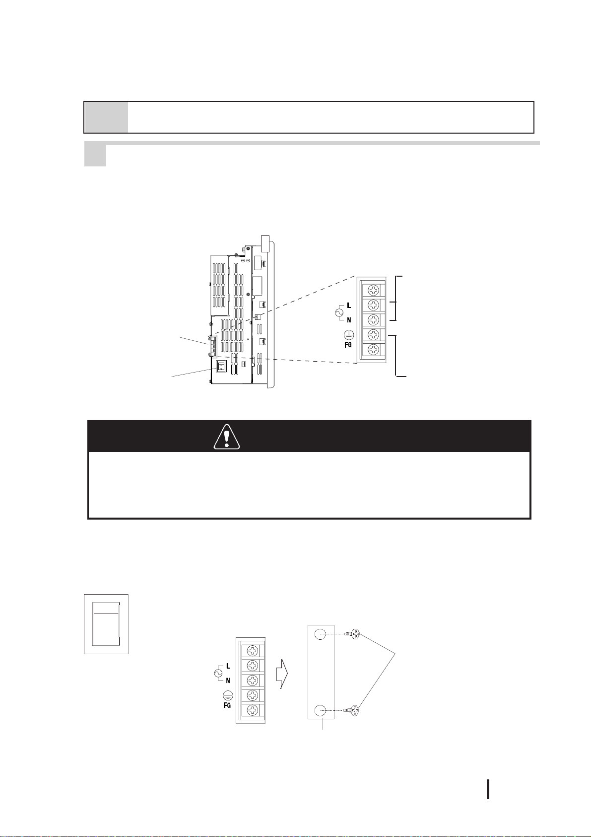
Installation and Wiring
4-2 Wiring the PL
1 Connecting the Power Cord
(Rear of PL)
Power T erminals
Power Input Terminals
Connecting these two terminals provides 100V to 240V
AC power.
L= live and N= Neutral
(screw size: M3)
Power Switch
PL-6921/PL-7921 (2-Slot type)
This terminal is connected
to the PL ’s frame (chassis).
WARNINGS
T o prevent electric shocks, be sure to turn the PL OFF befor e connecting the power cord.
T o avoid the dangers of fire, electric hazards and equipment damage, be sure to use
only the specified power supply voltage when operating the PL.
Use the following steps when connecting the power cord to the PL’s power terminals.
POWER
I
I:ON
o:OFF
o
1) Confirm that the power switch is
turned OFF. Then, remove the
power terminal’s transparent plastic cover.
Screws
PL-6920/PL-7920 Series User Manual
Transparent Cover
4 - 7

Installation and Wiring
Black
2) Loosen and remove the middle three(3)
screws from the terminal strip. Align the
crimp terminals with each screw hole,
and tighten the screws.
White
Green/Yellow
Attachment
Screws
Transparent
Cover
• Crimp Terminal Types :
V1.25-3, by J.S.T. or equivalent (JIS
standard part number : RAV1.25-3)
• Crimp terminals must be the same
as shown below.
φφ
φ
φφ
3.2 mm or larger
^
Max. 6.0 mm
^
^
• The colors in the figure above are
for the cord which came with
the PL.
• This power cord is designed only
for AC100/1 15V use. Be sure to
use a different cord when using
other than AC100/115V power.
3) Reattach the terminal strip’s transparent cover with the attachment screws.
4 - 8
PL-6920/PL-7920 Series User Manual

Installation and Wiring
2 Power Supply Cautions
When connecting the PL unit’s AC power terminals, please be aware of the following:
Constant
voltage
transformer
Insulating
transformer
AC100V
Main power
source
Twisted-pair
cord
Twisted-pair
cord
PL power
source
I/O power
source
PL
FG
PL
FG
PL
I/O
device
• If voltage fluctuations are expected to vary beyond the specified range, connect a constant
voltage transformer.
For information about the specified
voltage, refer to “2-1 General
Specifications”
• Use a low-noise power supply both between the lines and between the PL and its
ground. If there is still excess noise, connect an insulating transformer (noise-prevention type) .
Be sure any constant or insulating
transformer used has a capacity of
200VA or more.
• Wire the power cords of the PL, I/O devices, and power supply devices separately .
Main power
source
AC 200V
Twisted-pair
AC
PL power
source
T1
T2
I/O power
source
Main circuit
power source
cord
E1
Lightning surge absorber
I/O
device
I/O
device
Power
device
PL
FG
E2
PL
• To improve noise immunity , it is recommended
to attach a ferrite core to the power cord.
• Isolate the main circuit (high voltage, large
current) line, I/O signal lines, and power cord,
and do not bind or group them together.
• To prevent damage from lightning, connect a
lightning surge absorber .
• Ground the lightning surge absorber
(E1) and the PL (E2) separately.
• Select a lightning surge absorber
which will not exceed the allowable
circuit voltage, even when the
voltage rises to the maximum.
PL-6920/PL-7920 Series User Manual
4 - 9

Installation and Wiring
3 Grounding Cautions
(a) Dedicated Ground
PL
(b) Shared Ground - allowed
PL
*1
Other
device
*1
Other
device
(c) Shared ground - not allowed
PL
Other
device
• Set up a dedicated ground when using
the rear panel’s FG terminal.
• If a dedicated ground is not possible, use
a shared ground, as shown in figure (b).
• Inside the PL unit, the SG (Signal
Ground) and FG (Frame Ground) terminals are connected to each other.
• When connecting an external device to
PL with the SG terminal, ensure that no
short-circuit loop is created when you set
up the system.
4
• The grounding point must be as close to
the PL as possible, and the grounding
wires must be as short as possible. If the
wires must be long, use thick, insulated
wires and run them through conduits.
Cautions When Connecting I/O Signal Lines
• I/O signal lines must be wired separately from the power circuit cable. If the
power circuit cable needs to be wired together with the input/output (I/O)
signal lines for any reason, use shielded cables and ground one end of the
shield to the PL’s FG terminal.
• To improve noise immunity, it is recommended to attach a ferrite core to the
power cord.
*1 Use a grounding resistance of 100Ω or less, and a 2mm2 or thicker wire, or your
country’s applicable standard. For details, contact your local PL distributor.
4 - 10
PL-6920/PL-7920 Series User Manual

Chapter
5System Setup
This chapter explains how to enter a PL-6920/PL-7920 Series unit's system settings, as well
as the cautions required both before and during set up.
5-1 Setup Procedures
System Setup
5-1 Setup Procedures
5-2 System Parameters
Normally, use only the factory (default) settings.
The following settings are those pre-set at the factory.
1) Connect a keyboard to the PL.
2) Turn the PL's power ON.
3) After the message "Press <DEL> to Enter SETUP" appears, press the [DEL]
key until the following screen appears.
CMOS Setup Utility - Copyright (C) 1984-2001 Award Software
Standard CMOS Features
Advanced BIOS Features
Advanced Chipset Features
Integrated Peripherals
Power Management Setup
PnP/PCI Configurations
PC Health Status
Frequency/Voltage Control
Load Fail-Safe Defaults
Load Optimized Defaults
Set Supervisor Password
Set User Password
Save & Exit Setup
Exit Without Setting
ESC: Quit ↑↓→←: Select Item
F10 : Save & Exit Setup
KEYBOARD ACTION KEYS
Provides a summary of the keyboard keys used to carry out the set up.
SYSTEM SETTING SELECTION AREA
Each of the titles (areas) listed here contains system setting items.
4) Use the arrow keys to move the cursor to the desired selection.
PL-6920/PL-7920 Series User Manual
Time,Date,Hard Disk Type...
5 - 1

System Setup
5-2 System Parameters
1 STANDARD CMOS FEATURES
Selecting the STANDARD CMOS FEATURES menu item produces the
following screen.
CMOS Setup Utility - Copyright (C) 1984-2001 Award Software
Standard CMOS Features
Date (mm:dd:yy): Tue,Jul 2 2001
Time (hh:mm:ss): 14 : 50 : 3
IDE Primary Master [IC25N020ATDA04-0]
IDE Primary Slave [None]
Drive A [1.44M, 3.5 in.]
Drive B [None]
Video [EGA/VGA]
Halt On [All,But Disk/Key]
Base Memory 640K
Externded Memory 129024K
Total Memory 130048K
↑↓→←: Move Enter:Select +/-/PU/PD:Value F10:Save ESC:Exit F1:General Help
F5:Previous Values F6:Fail-Safe Defaults F7:Optimized Defaults
Menu Level
Change the day, month,
year and century
Item Help
Date/Time
This data sets the PL's internal time and date.
Hours :00 - 23
Minutes :00 - 59
Seconds :00 - 59
IDE Primary Master (Slave)
Displays the size of the Hard Disk installed in the PL. Pressing the
[Enter] key will call up the Parameter settings menu.
For details, refer to 5-2-2 IDE HDD Auto Detection
5 - 2
Drive A (B)
This setting determines the format used by the PL's internal floppy disk
drive. The available settings are [None], [720K - 3.5in], [1.44M -
3.5in], or [2.88M, 3.5in]. The factory settings are Drive A [1.44M -
3.5in] and Drive B [None] and recommended for most users.
Video
The selections for the screen (video) mode. The available settings are
[EGA/VGA], [CGA40], [CGA80] and [MONO]. The [EGA/VGA]
selection is factory set and recommended for most users.
PL-6920/PL-7920 Series User Manual

System Setup
Halt On
Designates the type of processing that will be performed when an error
occurs during the Initial Start-Up's Self Test. The [All But Disk /Key]
selection is factory set and recommended for most users.
[All Errors] : Displays all errors and stops the unit.
[No Errors] : Displays all errors and does not stop the unit.
[All,But Keyboard] : Displays all errors, except for those related to
the keyboard, and stops the unit. If the User has
no keyboard connected, please use this setting.
[All,But Diskette] : Displays all errors, except for those related to
the disk drive (FDD), and stops the unit.
[All,But Disk/Key] : Displays all errors, except for those related to the disk
drive (FDD) and keyboard, and then stops the unit.
PL-6920/PL-7920 Series User Manual
5 - 3

System Setup
2 IDE HDD AUTO DETECTION
The Standard CMOS Features menu is used to select the IDE Primary Master
and the IDE Primary Slave.
CMOS Setup Utility - Copyright (C) 1984-2001 Award Software
IDE Primary Master
IDE HDD Auto-Detection [Press Enter]
IDE Primary Slave [Auto]
Access Mode [Auto]
Capacity
Cylinder
Head
Precomp
Landing Zone
Sector
↑↓→←:Move Enter:Select +/-/PU/PD: Value F10:Save ESC:Exit F1:General Help
F5:Previous Values F6:Fail-Safe Defaults F7:Optimized Defaults
IDE HDD Auto-Detection
Menu Level
To auto-detec the HDD's size,
head.... on this channel
Item Help
This setting detects the hard disk connected to the IDE interface.
IDE Primary Master (Slave)
This setting designates the IDE type Hard Disk's parameter setting method. The
available settings are [None], [Auto], or [Manual]. The factory default setting is
[Auto] and is recommended for most users.
5 - 4
Access Mode
This setting designates the IDE type Hard Disk's access mode. The available
settings are [CHS], [LBA], [Large], or [Auto]. The factory default setting is
[Auto] and is recommended for most users.
Capacity/Cylinder/Head/Precomp/Landing Zone/ Sector
These settings designate individual IDE type Hard Disk parameter settings. These
can only be set when the [IDE Primary Master (Slave)] setting is set to [Manual].
When the [IDE Primary Master (Slave)] setting is set to [Auto], these values are
automaticaly detected. Capacity is set automaticaly.
PL-6920/PL-7920 Series User Manual

3 ADVANCED BIOS FEATURES
Selecting the ADVANCED BIOS FEATURES menu item calls up the following screen.
CMOS Setup Utility - Copyright (C) 1984-2001 Award Software
Advanced BIOS Features
Virus Warning [Disabled]
CPU Internal Cache [Enabled]
External Cache [Enabled]
CPU L2 Cache ECC Checking [Enabled]
Processor Number Feature [Enabled]
Quick Power On Self Test [Enabled]
First Boot Device [Floppy]
Second Boot Device [HDD-0]
Third Boot Device [CDROM]
Fourth Boot Device [Disabled]
Swap Floopy Drive [Disabled]
Boot Up Floppy Seek [Enabled]
Boot Up NumLock Status [On]
Gate A20 Option [Fast]
Typematic Rate Setting [Disabled]
x Typematic Rate(Chars/Sec) [6]
x Typematic Delay (Msec) [250]
Security Option [Set up]
PS/2 Mouse Function Ctrl [Enabled]
OS Select For DRAM > 64MB [Non-OS2]
HDD S.M.A.R.T. Capability [Disabled]
Report No FDD For WIN 95 [No]
System Setup
Item Help
Menu Level
Allows you to choose
the VIRUS warning
feature for IDE Hard
Disk boot sector
protection. If this
function is enabled
and someone attempts to
write data into this
area, BIOS will show a
warning message on
screen and an alarm will beep
↑↓→←:Move Enter:Select +/-/PU/PD:Value F10:Save ESC:Exit F1:General Help
F5:Previous Values F6:Fail-Safe Defaults F7:Optimized Defaults
Virus Warning
This setting determines whether to display a warning when a write to the boot
sector is attempted. The available settings are [Enabled] or [Disabled]. The
factory default setting is [Disabled] and is recommended for most users.
CPU Internal Cache
This setting determines the usage of the CPU's internal cache memory. The
available settings are [Disabled] or [Enabled]. The factory default setting is
[Enabled] and is recommended for most users.
External Cache
This setting determines the usage of the external cache memory (L2). The available settings are [Disabled] or [Enabled]. The factory default setting is [Enabled]
and is recommended for most users.
CPU L2 Cache ECC Checking
This setting turns ON or OFF external(L2) Cache Memory's ECC (Error Check
Correction). The available settings are [Disabled] and [Enabled]. The factory
default setting is [Enabled] and is recommended for most users.
Processor Number Feature
This option is for the Pentium® III processor. If this setting is set to Enabled, it will
check the CPU's serial number. If you do not need to know the serial number, set
this option to [Disabled]. If this is turned ON, use the "Serial Number Control
Program" found on Intel's web site to perform the check.
PL-6920/PL-7920 Series User Manual
5 - 5

System Setup
Quick Power On Self Test
This setting determines whether the quick self test is performed when the power is
turned on. The available settings are [Disabled] or [Enabled]. The factory
default setting is [Enabled] and is recommended for most users.
First/ Second/ Third/ Fourth Boot Device
The selections for the search drive sequence of the operating system. The available settings are [Floppy], [HDD-0]
*1
1]
Swap Floppy Drive
This setting swaps Drives A and B. The available settings are [Disabled] or [Enabled].
The factory default setting is [Disabled] and is recommended for most users.
Boot Up Floppy Seek
The setting checks whether the floppy disk drive is installed during the system boot-up
process. The available settings are [Disabled] or [Enabled]. The factory default setting
is [Enabled] and is recommended for most users.
*1
, [LS120], [HD-0], [SCSI], [CDROM], [HDD-
, [ZIP100], [LAN], [ISA-FDD], and [Disabled].
Boot Up Numlock Status
This setting specifies the Numlock key status upon the startup. The available settings
are [On] and [Off]. The factory default setting is [On] and is recommended for most
users.
Gate A20 Option
The available settings are [Normal] and [Fast]. When [Normal] is selected, the Keyboard control will be employed to control Gate A20. When [Fast] is selected, the
Chipset will be employed. The factory default setting is [Fast] and is recommended for
most users.
Typematic Rate Setting
The setting specifies the keyboard speed used when repeating characters.
The available settings are [Enabled] and [Disabled]. The factory default setting is
[Disabled] and is recommended for most users.
* 1This has a different meaning from the expansion slot position codes "HDD0" and
"HDD1" stamped into the side of the PL unit's metal chassis.
HDD-0:
-When only one HDD unit is installed.
The HDD setting is recognized as "HDD-0" and is not related to the Master/Slave
items.
-When 2 HDD units are installed.
An HDD unit designated as the Master HDD is recognized as "HDD-0".
HDD-1:
-When only one HDD unit is installed.
OS cannot be started. Be sure the BIOS setting is "HDD-0".
-When 2 HDD units are installed.
An HDD unit designated as the Slave HDD is recognized as "HDD-1".
5 - 6
PL-6920/PL-7920 Series User Manual

System Setup
Typematic Rate (Chars/ Sec)
This setting specifies the actual typematic rate (repeated character input per second)
when the [T ypematic Rate Setting] option is set to [Enabled]. The settings are used to
determine how many repeats are performed in one second. The factory default setting is
[6] and is recommended for most users.
Typematic Delay (Msec)
When [T ypematic Rate Setting] is set to [Enabled], this setting determines the delay
period until the initial repetition is started. The [250] selection is factory set and is
recommended for most users.
Security Option
This setting designates the area to request a password. If during BIOS setup you are
requested to enter a password, select [Setup]. If during System Startup you are requested to enter a password, select [System]. This setting is NOT available if the
password is not set in the [SET SUPER VISOR PASSWORD] or [SET USER P ASSWORD] areas. The factory default setting is [Setup] and is recommended for most
users.
[SET SUPERVISOR PASSWORD] Refer to 5-2-14 Set Supervisor Password
[SET USER PASSWORD] Refer to 5-2-15 Set User Password
PS/2 Mouse Function Ctrl
The available selections are [Enabled] and [Disabled], [Enabled] is factory
set and recommended for most users.
OS Select For DRAM > 64MB
The available settings are [Non-OS2] and [OS2]. The factory default settting is
[Non-OS2] and is recommended for most users.
HDD S.M.A.R.T Capability
This feature sets the HDD unit's SMART (Self-Monitoring Analysis and
Reporting Technology). The available selections are [Enabled] and
[Disabled], [Disabled] is factory set and recommended for most users.
Report No FDD For WIN 95
This setting determines if the FDD node is reported by BIOS to WIN95. The
available settings are [No] and [Yes]. The factory default setting is [No] and is
recommended for most users.
PL-6920/PL-7920 Series User Manual
5 - 7

System Setup
4 ADVANCED CHIPSET FEATURES
Selecting the ADV ANCED CHIPSET FEATURES menu item calls up the
following screen.
CMOS Setup Utility - Copyright (C) 1984-2001 Award Software
Advanced Chipset Featrues
SDRAM CAS Latency Time [3]
SDRAM Cycle Time Tras/Trc [Auto]
SDRAM RAS-to-CAS Delay [Auto]
SDRAM RAS Precharge Time [Auto]
System BIOS Cacheable [Enabled]
Video BIOS Cacheable [Enabled]
Memory Hole At 15M-16M [Disabled]
CPU Latency Timer [Enabled]
Delayed Transaction [Enabled]
On-Chip Video Window Size [64MB]
↑↓→←:Move Enter:Select +/-/PU/PD:Value F10:Save ESC:Exit F1:General Help
F5:Previous Values F6:Fail-Safe Defaults F7:Optimized Defaults
Menu Level
Item Help
SDRAM CAS Latency Time
Designates the clock counts used, from the enabling of CAS to the start of
the burst transmission. Can be set to either [3] or [2]. Factory default
setting is [3] and strongly recommended for most users.
SDRAM Cycle Time Trans/Trc
Designates the number of SLCK's for an access cycle, i.e. the minumum
required time from when a bank is activated to the activation of an
identical bank. Settings are [7/9], [5/7] or [Auto]. Factory default setting is
[Auto] and strongly recommended for most users.
5 - 8
SDRAM RAS-to-CAS Delay
Designates the timing delay used between RAS and CAS strobe signals.
Settings are [2], [3], or [Auto]. Factory default setting is [Auto] and
strongly recommended for most users.
SDRAM RAS Precharge Time
Designates the pre-charge time value used, to allow RAS to accumulte its
charge before DRAM refresh. Settings are [2], [3], or [Auto]. Factory
default setting is [Auto] and strongly recommended for most users.
System BIOS Cacheable
Sets whether the System BIOS’ Cache is used or not. When the OS is set to
use this cache, the PL unit’s processing speed will increase. Settings
available are [Enabled] and [Disabled]. The factory setting is [Enabled]
and is recommended for most users.
PL-6920/PL-7920 Series User Manual

System Setup
Video BIOS Cacheable
Sets whether the Video BIOS’ Cache is used or not. Settings available are [Enabled] and [Disabled]. The factory setting is [Enabled]. When this feature is
[Enabled], the OS’ BIOS ROM range available for caching is from C0000h F7FFFh, which will improve the video performance. However, if another program
tries to write to this area of memory, a system error may occur.
Memory Hole At 15M-16M
This setting determines whether to designate the memory space from 15MB to
16MB as the buffer area for the ISA bus card. The available settings are [Disabled] and [Enabled]. The factory default setting is [Disabled] and is recommended for most users.
CPU Latency Timer
If Enabled, a deferrable CPU cycle will only be Deferred after it has been in a
Snoop Stall for 31 scans and another ADS# has arrived. If Disabled, changeable
CPU cycles will be changed when an ADS number is received.
Delayed Transaction
Designates the length of the pre-charge time. The available settings are [Enabled]
and [Disabled]. The factory default setting is [Enabled] and is recommended.
On-Chip Video Window Size
Designates the on-chip video window size used by the VGA driver. The available
settings are [Disabled] and [64MB]. The factory default setting is [64MB] and is
recommended for most users.
PL-6920/PL-7920 Series User Manual
5 - 9

System Setup
5 INTEGRATED PERIPHERALS
Selecting INTEGRATED PERIPHERALS SETUP menu item displays the
following screen.
CMOS Setup Utility - Copyright (C) 1984-2001 Award Software
Integrated Peripherals
On-Chip Primary PCI IDE [Enabled]
IDE Primary Master PIO [Auto]
IDE Primary Slave PIO [Auto]
IDE Primary Master UDMA [Auto]
IDE Primary Slave UDMA [Auto]
USB Controller [Disabled]
x USB Keyboard Support Disabled
Init Display First [PCI Slot]
AC97 Audio [Disabled]
Onboard LAN [Disabled]
IDE HDD Block Mode [Enabled]
POWER ON Function [BUTTON ONLY]
x KB Power ON Password Enter
x Hot Key Power On Ctrl-F1
Onboard FDC Controller [Enabled]
Onboard Serial Port 1 [3F8/IRQ4]
Onboard Serial Port 2 [2F8/IRQ3]
Onboard Serial Port 3 [3E8H/IRQ9]
Onboard Serial Port 4 [2E8H/IRQ10]
Onboard Parallel Port [3BC/IRQ7]
Parallel Port Mode [SP P ]
x EPP Mode Select EPP1,7
x ECP Mode Use DMA 3
PWRON After PWR-Fail [ON]
↑↓→←:Move Enter:Select +/-/PU/PD: Value F10:Save ESC:Exit F1:General Help
F5:Previous Values F6:Fail-Safe Defaults F7:Optimized Defaults
Item Help
Menu Level
On-Chip Primary PCI IDE
Designates the internal IDE port's setting. The two selections available
are [Disabled] and [Enabled]. The [Enabled] selection is factory set and
recommended for most users.
IDE Primary Master (Slave) PIO
Designates the Master Drive's Operation Mode. Only after the "Internal
PCI/IDE" has been set to [Primary] can these IDE Primary Master PIO
settings be entered. The two selections available are [Auto], [Mode0],
[Mode1], [Mode2], [Mode3], and [Mode4]. The [Auto] selection is
factory set and recommended for most users. When using the CD-ROM
drive, select [Mode 2].
IDE Primary Master (Slave) UDMA
Designates the Master Drive's UDMA Operation Mode. The two
selections available are [Auto] or [Disabled]. The [Auto] selection is
factory set and recommended for most users.When using the CD-ROM
drive, select [Mode 2].
5 - 10
PL-6920/PL-7920 Series User Manual

System Setup
USB Controller
Select [Enabled] or [Disable] when attaching a USB device. The
[Disabled] selection is factory set and recommended for most users. When
using the USB I/F or
this item to “Enabled”.
If a USB device is connected, change the [USB Controller]
and [PnP/PCI Configration] menu's [Assign IRQ For USB]
settings to [Enabled].
USB Keyboard Support
Select [Enabled] or [Disable] if your system contains a USB controller
and you wish to use a USB keyboard. The available settings are [Disabled] and [Enabled]. The factory default setting is [Disabled]. Either
[Disabled] or [Enabled] can be selected. If, however, the USB Controller
is set to [Disabled], this setting cannot be changed.
If a USB device is connected, change the [USB Controller]
and [PnP/PCI Configration] menu's [Assign IRQ For USB]
settings to [Enabled].
the USB connector for connecting the touch panel, set
Init Display First
When both a PCI and an AGP device are installed, this setting designates
which will output first. Settings are [PCI slot] or [Onboard/AGP]. The
factory default setting is [PCI slot].
AC97 Audio
Enables or disables the 815 chipset family to support AC97 Audio. The
available settings are [Disabled] and [Auto]. The factory default setting
is [Disabled].
Onboard LAN
The available settings are [Disabled] and [Enabled]. The factory default
setting is [Disabled].
IDE HDD Block Mode
This setting determines whether to enable the Block Mode on the HDD supporting the Block Mode. The available settings are [Disabled] and [Enabled].
The factory default setting is [Enabled] and is recommended for most users.
Power ON Function
This feature is not supported.
KB Power ON Password
This feature is not supported.
Hot Key Power ON
This feature is not supported.
PL-6920/PL-7920 Series User Manual
5 - 11

System Setup
Onboard FDC Controller
Designates whether the PL's FDD(Floppy Disk Drive) controller is used or
not. Settings available are [Disabled] or [Enabled]. The [Enabled] selection
is factory set.
Onboard Serial Port 1
Designates the PL's Serial Port 1 I/O address. The selections include
[Disabled], [Auto], [3F8/IRQ4], [2F8/IRQ3], [3E8/IRQ4] and [2E8/IRQ3].
The [3F8/IRQ4] selection is factory set and recommended for most users.
Onboard Serial Port 2
Designates the PL's Serial Port2 I/O address. The selections include
[Disabled], [Auto], [3F8/IRQ4], [2F8/IRQ3], [3E8/IRQ4] and [2E8/IRQ3].
The [2F8/IRQ3] selection is factory set and recommended for most users.
Onboard Serial Port 3
Designates the PL's Serial Port3 address setting. The selections include
[Disabled], [3F8H/IRQ9], [2F8H/IRQ10], [3E8H/IRQ9] or [2E8H/IRQ10].
The [3E8H/IRQ9] selection is factory set and recommended for most users.
Onboard Serial Port 4
Designates the PL's Serial Port3 address setting. The selections include
[Disabled], [3F8H/IRQ9], [2F8H/IRQ10], [3E8H/IRQ9] or [2E8H/IRQ10].
The [2E8H/IRQ10] selection is factory set and recommended for most
users.When using the USB connector for connecting the touch panel, set
this item to “Disabled”.
Onboard Parallel Port
Selects the PL Parallel Port 1's I/O Address. The selections include
[Disabled], [3BC/IRQ7], [378/IRQ7] or [278/IRQ5]. The [3BC/IRQ7]
selection is factory set and recommended for most users.
Parallel Port Mode
Here, the parallel port's operation mode can be selected ([SPP], [EPP1.7],
[EPP1.9], [ECP], or [ECP
recommended for most users. When either [ECP] or [ECP+EPP] is
selected, the [ECP Mode Use DMA] setting can be used.
EPP Mode Select
When [EPP] or [ECP + EPP] mode is selected, this feature allows you to
select the EPP mode protocol. [EPP 1.7] or [EPP 1.9] can be selected.
ECP Mode Use DMA
Designates the ECP mode's DMA channel. [1] and [3] are available
selections, however, this item can be set only when the Parallel Port Mode is
set to either [ECP] or [ECP+EPP].
PWRON After PWR-Fail
This feature is not supported.
+
EPP]). Normally, [SPP] is used and
5 - 12
PL-6920/PL-7920 Series User Manual

6 POWER MANAGEMENT SETUP
Selecting the POWER MANAGEMENT SETUP menu item calls up the
following screen.
CMOS Setup Utility - Copyright (C) 1984-2001 Award Software
Power Management Setup
System Setup
Power Management [ User Define]
Video Off Method [V/H
Video Off In Suspend [Yes]
Suspend Type [Stop Grant]
Suspend Mode [Disabled]
HDD Power Down [Disabled]
Soft-Off by PWR-BTTN [Instant-Off]
Power On by Ring [Disabled]
CPU Thermal-Throttling [50.0%]
**Reload Global Timer Events**
Primary IDE 0 [Disabled]
Primary IDE 1 [Disabled]
FDD,COM,LPT Port [Disabled]
PCI PIRQ[A-D]# [Disabled]
↑↓→←:Move Enter:Select +/-/PU/PD:Value F10:Save ESC:Exit F1:General Help
F5:Previous Values F6:Fail-Safe Defaults F7:Optimized Defaults
SYNC+Blank]
Menu Level
Item Help
Power Management
You can choose from three power management options. These are [User
Define], [Min Saving] or [Max Saving]. The [User Define] selection is
factory set and recommended for most users.
Video Off Method
This setting determines the method to blank the display screen. The available
settings are [Blank Screen], [V/H SYNC+Blank], and [DPMS Supported]. The
[Blank Screen] selection blanks the display. The [V/H SYNC+Blank] blanks
the display and also suspends the Vertical/Horizontal synchronization signal of
the display. The [DPMS Supported] selection controls the operation when a
CRT that supports DPMS is used. The factory default setting is [V/H
SYNC+Blank] and is recommended for most users.
Video Off In Suspend
Designates how the monitor is blanked. The available settings are [Yes] and
[No]. The factory default setting is [Yes].
Suspend Type
Designates the type of suspend method used. The available settings are [Stop
Grant] and [PWRON Suspend]. The factory default setting is [Stop Grant].
Suspend Mode
When enabled, designates the period of time before all devices except the CPU
are shut down. The available settings are [1Min], [2Min], [4Min], [8Min],
[12Min], [20Min], [30Min], [40Min], [1Hour] and [Disabled]. The factory
default setting is [Disabled].
PL-6920/PL-7920 Series User Manual
5 - 13

System Setup
HDD Power Down
Designates the length of time until the motor of the hard disk stops. The
available selections are[1Min] [15Min] and [Disabled]. [Disabled] is
factory set and recommended for most users.
Soft-Off by PWR-BTTN
Set up the power buttons used for software control. Available selections are
[Delay 4 sec] and [Instant-off], however, since the PL unit has no power button
for software control, be sure to select [Instant-off]. Factory setting is [Instantoff].
Power On by Ring
When enabled, the system will boot up when the modem receives a call. When
disabled, the sytstem will ignore all calls received by the modem. The available
settings are [Enabled] and [Disabled]. The factory default setting is [Disabled].
CPU Thermal-Throttling
Designates the CPU THRM-Throttling rate. The available settings are [12.5%],
[25.0%], [37.5%], [50.0%], [62.5%], [75%] and [87.5%]. The factory default
setting is [50.0%].
**Reload Global Timer Events**
This feature sets the event that reloads the timer used to designate the amount
(period) of PL unit idle time prior to changing to energy-saving mode. Thus,
when an event occurs for any of the items in this area that are set to [Enabled],
the system will reload the Timer.
5 - 14
PL-6920/PL-7920 Series User Manual

7 PNP/PCI CONFIGURATION
Selecting the PnP/PCI CONFIGURATION menu item displays the following screen.
CMOS Setup Utility - Copyright (C) 1984-2001 Award Software
PNP/PCI Configurations
System Setup
PNP OS Installed [No]
Reset Configuration Data [Disabled]
Resources Controlled By [Manual]
IRQ Resources [Press Enter]
DMA Resources [Press Enter]
PCI/VGA Palette Snoop [Disabled]
x Assign IRQ For VGA Enabled
Assign IRQ For USB [Disabled]
↑↓→←:Move Enter:Select +/-/PU/PD:Value F10:Save ESC:Exit F1:General Help
F5:Previous Values F6:Fail-Safe Defaults F7:Optimized Defaults
PNP OS Installed
Menu Level
Default is Disabled.
Select Enabled to
reset Extended System
Configuration Data
(ESCD) when you exit
Setup if you have
installed a new add-on
and the system
reconfiguration has
caused such a serious
conflict that the OS
cannot boot
Item Help
Setting used when the user's OS complies with Plug-And-Play standards.
The selection options are either [Yes] or [No]. The [No] setting is
factory set and recommended for most users.
Reset Configuration Data
Designates whether ESCD (Extended System Configuration Data) data
should be erased or not. The two selections available are [Disabled] and
[Enabled]. The [Disabled] selection is factory set and recommended for
most users.
Resources Controlled By
The Plug and Play feature allows you to designate whether the allocation
of I/O Port, IRQ and DMA resources is performed automatically or
manually. The two selections available are [Manual] or [Auto(ESCD)].
If [Auto(ESCD)] is selected, the IRQ Resources and DMA Resources
selection will be disabled. The [Manual] selection is factory set and
recommended for most users.
IRQ Resources
When resources are controlled manually, assign each system interrupt
used a type, that reflects the type of device using the interrupt.
refer to 5-2-8 IRQ Resources
DMA Resources
This menu provides control over the DMA resources used.
refer to 5-2-9 DMA Resources
PCI/VGA Pallet Snoop
However, depending on the VGA or MPEG board used, select [Enabled].
For setup details, refer to that board's installation guide.
PL-6920/PL-7920 Series User Manual
5 - 15

System Setup
Assign IRQ for VGA
Designates whether the VGA interrupt is allocated or not. Set to
[Enabled].
Assign IRQ for USB
The two selections available are [Disabled] and [Enabled]. The
[Disabled] selection is factory set and recommended for most
users.When using the USB I/F or the USB connector for connecting the
touch panel, set this item to “Enabled”.
If a USB device is connected, change the [INTEGRATED PERIPHERALS] menu's [USB Controller] and [Assign IRQ For
USB] settings to [Enabled].
8 IRQ Resources
Select IRQ Resources from the PnP/ PCI Configurations menu and the following
screen will appear .
CMOS Setup Utility - Copyright (C) 1984-2001 Award Software
IRQ Resources
IRQ-3 assigned to [Legacy ISA]
IRQ-4 assigned to [Legacy ISA]
IRQ-5 assigned to [PCI/ISA PnP]
IRQ-7 assigned to [Legacy ISA]
IRQ-9 assigned to [Legacy ISA]
IRQ-10 assigned to [Legacy ISA]
IRQ-11 assigned to [PCI/ISA PnP]
IRQ-12 assigned to [Legacy ISA]
IRQ-14 assigned to [Legacy ISA]
IRQ-15 assigned to [PCI/ISA PnP]
↑↓→←:Move Enter:Select +/-/PU/PD:Value F10:Save ESC:Exit F1:General Help
F5:Previous Values F6:Fail-Safe Defaults F7:Optimized Defaults
IRQ-3 assigned to ~ IRQ-15 assigned to
Menu Level
Legacy ISA for devices
compliant with the
original PC AT bus
specification, PCI/ISA
PnP for devices
compliant with the
Plug and Play standard
whether designed for
PCI or ISA bus
architecture
Item Help
This setting determines the type of device assigned to the IRQ. This function is
available when the [Resource Control By] option under the [PnP/ PCI Configurations] menu is set to [Manual].
[PCI/ISA PnP]..Select to use a PnP-ready PCI or ISA card.
5 - 16
[Legacy ISA] ....Select to use a non-PnP ISA card.
The initial settings are as shown below.
Initial Value Initial Value
IRQ-3 ass igned to Legacy I S A IRQ-10 assigned to Legacy I S A
IRQ-4 ass igned to Legacy I S A IRQ-11 assigned to PCI /IS A PnP
IRQ-5 ass igned to P CI /IS A PnP IRQ-12 assigned t o Legacy I S A
IRQ-7 ass igned to Legacy I S A IRQ-14 assigned to Legacy I S A
IRQ-9 ass igned to Legacy I S A IRQ-15 assigned to PCI /IS A PnP
PL-6920/PL-7920 Series User Manual

9 DMA Resources
Selecting DMA Resources from the PnP/PCI Configuration menu and the following screen will appear.
CMOS Setup Utility - Copyright (C) 1984-2001 Award Software
System Setup
DMA Resources
DMA-0 assigned to [PCI/ISA PnP]
DMA-1 assigned to [PCI/ISA PnP]
DMA-3 assigned to [PCI/ISA PnP]
DMA-5 assigned to [PCI/ISA PnP]
DMA-6 assigned to [PCI/ISA PnP]
DMA-7 assigned to [PCI/ISA PnP]
↑↓→←:Move Enter:Select +/-/PU/PD: Value F10 :Save ESC:Exit F1:General Help
F5:Previous Values F6:Fail-Safe Defaults F7:Optimized Defaults
DMA-0 assigned to ~ DMA-7 assigned to
Menu Level
Legacy ISA for devices
compliant with the
original PC AT bus
specification, PCI/ISA
PnP for devices
compliant with the
Plug and Play standard
whether designed for
PCI or ISA bus
architecture
Item Help
This setting determines the type of device assigned to the port address. This
function is available when the [Resource Control By] option under the [PnP/PCI
Configurations] menu is set to [Manual].
[PCI/ISA PnP]...Select to use a PnP PCI or ISA card.
[Legacy ISA]...Select to use a non-PnP ISA card.
The initial settings are as shown below.
Initial Value Initial Value
DMA -0 as sign ed t o PCI / ISA PnP DMA -5 as sign ed t o PCI /IS A PnP
DMA -1 as sign ed t o PCI / ISA PnP DMA -6 as sign ed t o PCI /IS A PnP
DMA -3 as sign ed t o PCI / ISA PnP DMA -7 as sign ed t o PCI /IS A PnP
PL-6920/PL-7920 Series User Manual
5 - 17

System Setup
10 PC Health Status
Select PC Health Status from the Main Menu and the following screen will
appear.
CMOS Setup Utility - Copyright (C) 1984-2001 Award Software
PC Health Status
System Warning Temperature [Disabled]
CPU Warning Temperature [Disabled]
Warning Voltage IN0(V) [Disabled]
Warning Voltage IN1(V) [Disabled]
Warning Voltage +3.3V [Disabled]
Warning Voltage +5V [Disabled]
Warning Voltage +12V [Disabled]
Warning Voltage -12V [Disabled]
Warning Voltage -5V [Disabled]
FAN1 Speed Limit [Disabled]
FAN2 Speed Limit [Disabled]
↑↓→←:Move Enter:Select +/-/PU/PD: Value F10:Save ESC:Exit F1:General Help
F5:Previous Values F6:Fail-Safe Defaults F7:Optimized Defaults
System Warning Temp
Menu Level
Item Help
This setting designates the system temperature at which a warning will be issued.
The available settings are [40°C/104°F], [45°C/113°F], [50°C/122°F], [55°C/
131°F], [60°C/140°F], [65°C/149°F], [70°C/158°F], [75°C/167°F], [80°C/176°F],
[85°C/185°F] and [Disabled]. The factory default setting is [Disabled].
CPU Warning Temperature
This setting designates the CPU temperature at which a warning will be issued.
The available settings are [40°C/104°F], [45°C/113°F], [50°C/122°F], [55°C/
131°F], [60°C/140°F], [65°C/149°F], [70°C/158°F], [75°C/167°F], [80°C/176°F],
[85°C/185°F] and [Disabled]. The factory default setting is [Disabled].
• When using a PentiumIII 1GHz CPU, select the [75°C/167°F] setting.
When using a PentiumIII 700MHz CPU, select the [85°C/185°F]
setting.
Warning Voltage IN0 (V)
When enabled, this setting determines the allowable range of the voltage of IN0
(Vcore) and designates that a warning will be issued if the temeperature exceeds
that level. The available settings are [+/-6%], [+/-8%] and [Disabled]. The factory
default setting is [Disabled].
Warning Voltage IN1 (V)
When enabled, this setting determines IN1's allowable voltage range and designates that a warning will be issued if the temeperature exceeds that level. The
available settings are [+/-6%], [+/-8%] and [Disabled]. The factory default setting
is [Disabled].
5 - 18
PL-6920/PL-7920 Series User Manual

System Setup
Warning Voltage +3.3V
When enabled, this setting designates that a warning will be issued if the
temeperature exceeds +3.3V's designated range. The available settings are [+/6%], [+/-8%] and [Disabled]. The factory default setting is [Disabled].
Warning Voltage +5V
When enabled, this setting designates that a warning will be issued if the
temeperature exceeds +5V's designated range. The available settings are [+/-6%],
[+/-8%] and [Disabled]. The factory default setting is [Disabled].
Warning Voltage +12V
When enabled, this setting designates that a warning will be issued if the
temeperature exceeds +12V's designated range. The available settings are [+/-6%],
[+/-8%] and [Disabled]. The factory default setting is [Disabled].
Warning Voltage -12V
When enabled, this setting designates that a warning will be issued if the
temeperature exceeds -12V's designated range. The available settings are [+/-6%],
[+/-8%] and [Disabled]. The factory default setting is [Disabled].
Warning Voltage -5V
When enabled, this setting designates that a warning will be issued if the
temeperature exceeds -5V's designated range. The available settings are [+/-6%],
[+/-8%] and [Disabled]. The factory default setting is [Disabled].
FAN1 Speed Limit
When enabled, this setting designates the allowed speed range for FAN1. The
available settings are [-30%], [-50%] and [Disabled]. The factory default setting
is [Disabled]. FAN1 is used for the CPU fan.
FAN2 Speed Limit
When enabled, this setting designates the allowed speed range for FAN2. The
available settings are [-30%], [-50%] and [Disabled]. The factory default setting
is [Disabled]. FAN2 is used for the power supply fan.
PL-6920/PL-7920 Series User Manual
5 - 19

System Setup
11 Frequency/Voltage Control
Selecting the Frequency/Voltage Control menu item produces the following
screen.
CMOS Setup Utility - Copyright (C) 1984-2001 Award Software
Frequency/Voltage Control
Auto Detect DIMM/PCI Clk [Enabled]
Spread Spectrum [Disabled]
Colck By Slight Adjust [100]
↑↓→←:Move Enter:Select +/-/PU/PD: Value F10:Save ESC:Exit F1:General Help
F5:Previous Values F6:Fail-Safe Defaults F7:Optimized Defaults
Auto Detect DIMM/PCI CLK
Menu Level
To auto-detect the
HDD's size, head... on
this channel
Item Help
This setting designates the auto detect of the DIMM/PCI clock. The available
settings are [Enabled] and [Disabled]. The factory default setting is [Enabled] and
strongly recommended for users.
Spread Spectrum
This setting allows you to set the CPU Clock/Spread Spectrum. The available
settings are [Enabled] and [Disabled]. The factory default setting is [Disabled]
and strongly recommended for users.
Clock By Slight Adjust
This setting sets the CPU's clock speed in either of three ranges - 133MHz to
166MHz, 100MHz to 132MHz, or 66MHz to 100MHz, depending on the CPU's
host clock. The available settings are [100] to [132]. The factory default setting is
[100] and strongly recommended for users.
5 - 20
PL-6920/PL-7920 Series User Manual

12 Load Fail-Safe Defaults
When the Menu screen's [Load Fail-Safe Defaults] is selected, you are able to
designated if the minimum number of System Settings is used or not. The
selections are [Y] and [N].
13 Load Optimized Defaults
Selecting [Load Optimized Defaults" designates whether or not you will set up
the PL unit's revert to the PL unit’s factory settings. The selections are [Y] and
[N].
When the PL unit uses its factory settings, the USB interface cannot
be used. For information about connecting the Touch Panel via the
USB connector, refer to 1.1.1 Setting Up the Touch Panel Connection.
For information about connecting the USB I/F, refer to 1.1.2 Using
the USB Interface.
System Setup
14 Set Supervisor Password
This password is used to change system information settings. It is designed to
prevent unapproved users from changing the system information settings.
Entering up to 8 characters here will overwrite the current password.
When you wish to have no password, click on the [Enter] key. Next, the words
"PASSWORD DISABLE" will appear, providing confirmation that the Password is no longer set.
When password input is required, use the [Advanced BIOS Features] area's
[Security Option] feature to enter the password. See 5.2.3 ADVANCED BIOS
FEATURES
15 Set User Password
This password is used to view system information settings. It is designed to
prevent unapproved users from viewing the system information settings.
Entering up to 8 characters here will overwrite the current password.
When you wish to have no password, click on the [Enter] key. Next, the words
"PASSWORD DISABLE" will appear, providing confirmation that the Password is no longer set.
When password input is required, use the [Advanced BIOS Features] area's
[Security Option] feature to enter the password. See 5.2.3 ADVANCED BIOS
FEATURES
PL-6920/PL-7920 Series User Manual
5 - 21

System Setup
• Selecting either "Set Supervisor Password" or "Set User Password"
allows you to view and change System Settings.
• When you enter a setting screen, "Set Supervisor Password" allows
you to view or modify System Settings, however, "Set User Password" allows you to only view System Settings.
16 Save & Exit Setup
This feature saves the settings entered in the Setup Utility and restarts the PL
unit.
17 Exit Without Setting
This feature quits the Setup Utility program without saving any settings entered.
5 - 22
PL-6920/PL-7920 Series User Manual

Setting Up Your PL OS
6-1 CD-ROM Contents
6-2 Setting Up Your PL OS
Chapter
6
Setting Up Your PL OS
Pro-face has prepared the following additional program files which are not supported by
the standard versions of the Windows
®
98 Second Edition, Windows® 2000 and Windows® XP operating systems. These
dows
files are located on the PL unit’s additional CD-ROM.
6-1 CD-ROM Contents
1 Diagram
The following tree-structure diagram shows the contents of the CD-ROM disk.
PL-X920 Series User Manual & Driver CD
[Driver]
[Chipset] Chipset Driver <OS>
[Win95] Windows
[Win98] Windows
[Win2000] Windows
[Display] Display Driver <OS>
[Win95] Windows
[DCOM] Windows95 DCOM Driver
[Win98] Windows
[Win2000] Windows
[WinNT] WindowsNT
[WinXP] Windows
[LAN] LAN Driver <OS>
[Win95] Windows
[Win98] Windows
[Win2000] Windows
[WinNT] WindowsNT
[Manual] <User Manual>
[ENG] PDF Manual (English)
[JPN] PDF Manual (Japanese)
[Reader] <PDF Data Reader>
[ENG] Acrobat Reader (English)
[JPN] Acrobat Reader (Japanese)
[Utility] <PL Utility Tools>
blset.exe Backlight Burnout Detection Program
[Win95] Windows
[Win98] Windows
[Win2000] Windows
[WinNT] WindowsNT
[WinXP] Windows
6-3 Installing Drivers
6-4 Application Features
®
6-5 Windows NT
Windows
®
95 OSR2 or higher, Windows NT® 4.0, Win-
PL Utility Setup <OS>
/ Windows® 2000 /
®
XP Cautions
®
95
®
98 Second Edition
®
2000
®
95
®
98 Second Edition
®
2000
®
4.0
®
XP
®
95
®
98 Second Edition
®
2000
®
4.0
®
95
®
98 Second Edition
®
2000
®
4.0
®
XP
PL-6920/PL-7920 Series User Manual
6 - 1

Setting Up Your PL OS
6-2 Setting Up Your PL OS
Two types of HDD units are available for your PL unit. One type is with no
preinstalled OS, the other has a preinstalled OS. Each type of HDD unit will have
its own setup procedures. This manual's explanation uses an HDD unit with no
proinstalled OS. For instructions of how to set up an HDD unit with a preinstalled
OS, refer to that HDD unit's Installation Guide.
1 Setting Up HDD with no installed OS
Prior to using the PL unit with the Windows® 95/Windows® 98 Second
Edition/WindowsNT® 4.0/Windows® 2000/Windows® XP operating system, certain utility software must be installed.
Installing the HDD Unit
A hard disk unit must be installed in the PL unit. Refer to PL-HD220
Installation Guide.
System Parameters Setup
System Parameters Setup must also be entered into the PL unit. After
these setting are entered, check that the HD drive is correctly recognized
by the PL.
Refer to PL-HD220 Installation Guide.
OS Setup
The PL unit is designed to operate using the following OS types.
The PL unit is designed to operate under the following standard Windows OS versions. PL operation with any other maker’s OS is not
guranteed.
Windows® 95 OSR2 or higher
Windows® 98 Second Edition
6 - 2
Windows NT® 4.0 (Windows Service Pack 3 or higher)
Windows® 2000
Windows® XP Professional
PL-6920/PL-7920 Series User Manual

Setting Up Your PL OS
PL Utility Setup
Use the “PL-X920 Series User Manual & Driver Disk CD” to install the necessary
drivers and utility software.
• To set up the PL, a PS/2 type (Mini DIN) keyboard is required.
• To use the PL unit’s touch panel, the Mouse Emulation Software (UPDD) is required. When installing this software, be sure to designate the COM port as
COM4. Visit our website (http://www.pro-face.com/otasuke/) and download the
Mouse Emulation Software (UPDD).
Installing Software from the CD-ROM
To install the software on the PL, Digital’s CD-ROM drive (PL-DK200) is required.
To set up the correct software for your PL unit’s OS, be sure to use the “Disk1”
folder’s “Setup.exe” file.
®
Ex. When running Windows
*1
D:Utility\Win98
\Disk1\Setup.exe
98 Second Edition, and the CD-ROM drive is “D”:
*1 Windows® 95 OSR2 or higher: “Win95”
Windows
Windows NT
Windows
Windows
®
98 Second Edition: “Win98”
®
4.0 (Windows Service Pack 3 or higher): “WinNT”
®
2000 : “Win2000”
®
XP: “WinXP”
PL-6920/PL-7920 Series User Manual
6 - 3
 Loading...