

Page 1
S SERIES
Active Subwoofers
USER’S MANUAL
MANUALE D’USO
96MAN0130-R E V.28/18
ENGLISH
ITALIANO
Page 2

2
Page 3

SUMMARY - ENGLISH
DISPOSAL OF OLD ELECTRICAL & ELECTRONIC EQUIPMENT ................................................................. 4
GENERAL SAFETY INSTRUCTIONS ........................................................................................................... 4
IN CASE OF FAULT ................................................................................................................................... 4
PACKAGING, SHIPPING AND COMPLAINT .............................................................................................. 4
WARRANTY AND PRODUCTS RETURN .................................................................................................... 4
MAINTENANCE AND DISCLAIMER ......................................................................................................... 5
POWER SUPPLY ...................................................................................................................................... 5
CONFORMITY ......................................................................................................................................... 5
INTRODUCTION ...................................................................................................................................... 6
DESCRIPTION .......................................................................................................................................... 6
INSTRUCTIONS ....................................................................................................................................... 6
1. LINE IN (XLR-JACK combo input) ................................................................................................. 7
2. LINK LEFT (XLR output balanced) ................................................................................................ 7
3. OUT LEFT (XLR output balanced) ................................................................................................ 7
4. INPUT RIGHT (combo XLR-JACK input)........................................................................................ 7
5. LINK RIGHT (XLR output balanced) ............................................................................................. 7
6. OUT RIGHT (XLR output balanced) ............................................................................................. 7
7. GND LIFT switch .......................................................................................................................... 7
8. FILTER switch ............................................................................................................................... 8
9. LEVEL control ............................................................................................................................... 8
10. SIGN/CLIP indicator ................................................................................................................. 8
11. PHASE 0° / 180° switch ............................................................................................................ 8
12. ON indicator ............................................................................................................................ 8
13. POWER switch ......................................................................................................................... 8
14. LINE VOLTAGE selector ............................................................................................................ 8
15. FUSE holder ............................................................................................................................. 8
16. AC~ socket ............................................................................................................................... 9
17. TECHNICAL SPECIFICATION ...................................................................................................... 9
18. ACCESSORIES ........................................................................................................................... 9
Mechanical Dimensions ...................................................................................................................... 17
S10A ................................................................................................................................................. 17
S12A ................................................................................................................................................. 17
S15A ................................................................................................................................................. 18
S18A ................................................................................................................................................. 18
Configurations ..................................................................................................................................... 19
Connectors .......................................................................................................................................... 19
3
Page 4

DISPOSAL OF OLD ELECTRICAL & ELECTRONIC EQUIPMENT
This marking shown on the product or its literature, indicates that it should not be disposed with
other household wastes at the end of its working life. To prevent possible harm to the enviroment
or human health from uncontrolled waste disposal, please separate this from other types of
wastes and recycle it responsibly to promote the sustainable reuse of material resources.
Household users should contact either the retailer where they purchased this product, or their
local government office, for details of where and how they can take this item for environmentally safe
recycling. Business users should contact their supplier and check the terms and conditions of the purchase
contract. This product should not be mixed with other commercial wastes for disposal.
GENERAL SAFETY INSTRUCTIONS
• CAUTION - Before using this product read carefully the following safety instructions. Take a look of this
manual entirely and preserve it for future reference. When using any electric product, basic precautions
should always be taken, including the following:
• To reduce the risk, close supervision is necessary when the product is used near children.
• Protect the apparatus from atmospheric agents and keep it away from water, rain and high humidity places.
• This product should be site away from heat sources such as radiators, lamps and any other device that generate heat.
• Care should be taken so that objects and liquids do not go inside the product.
• The product should be connected to a power supply only of the type described on the operating
instructions or as marked on the product.
IN CASE OF FAULT
• In case of fault or maintenance this product should be inspected only by qualified service personnel when:
• Liquids have spilled inside the product.
• The product has fallen and been damaged.
• The product does not appear to operate normally or exhibits a marked change in performance.
• Do not operate on the product, it has no user-serviceable parts inside.
• Refer servicing to an authorized maintenance centre.
PACKAGING, SHIPPING AND COMPLAINT
• This unit package has been submitted to ISTA 1A integrity tests. We suggest you control the unit
conditions immediately after unpacking it.
• If any damage is found, immediately advise the dealer. Keep all unit packaging parts to allow inspection.
• Proel is not responsible for any damage that occurs during shipment.
• Products are sold “delivered ex warehouse” and shipment is at charge and risk of the buyer.
• Possible damages to unit should be immediately notified to forwarder. Each complaint for manumitted
package should be done within eight days from product receipt.
WARRANTY AND PRODUCTS RETURN
• Proel products have operating warranty and comply their specifications, as stated by manufacturer.
• Proel warrants all materials, workmanship and proper operation of this product for a period of two years
from the original date of purchase. If any defects are found in the materials or workmanship or if the
product fails to function properly during the applicable warranty period, the owner should inform about
these defects the dealer or the distributor, providing receipt or invoice of date of purchase and defect
4
Page 5

detailed description. This warranty does not extend to damage resulting from improper installation,
FCC COMPLIANCE NOTICE
This device complies with part 15 of the FCC rules. Operation is subject to the following two conditions:
may cause undesired
se harmful interference to radio or television reception, which can be determined
misuse, neglect or abuse. Proel S.p.A. will verify damage on returned units, and when the unit has been
properly used and warranty is still valid, then the unit will be replaced or repaired. Proel S.p.A. is not
responsible for any "direct damage" or "indirect damage" caused by product defectiveness.
MAINTENANCE AND DISCLAIMER
• Clean only with dry cloth.
• Proel products have been expressly designed for audio application, with signals in audio range (20Hz to
20kHz). Proel has no liability for damages caused in case of lack of maintenance, modifications, improper
use or improper installation non-applying safety instructions.
• Proel S.p.A. reserves the right to change these specifications at any time without notice.
• Proel S.p.A. declines any liability for damages to objects or persons caused by lack of maintenance,
improper use, installation not performed with safety precautions and at the state of the art.
POWER SUPPLY
• This apparatus should only be connected to power source type specified in this owner’s manual or on the unit.
• If the supplied AC power cable plug is different from the wall socket, please contact an electrician to
change the AC power plug.
• Hold the plug and the wall outlet while disconnecting the unit from AC power.
• If the unit will not be used for a long period of time, please unplug the power cord from AC power outlet.
• To avoid unit power cord damage, please do not strain the AC power cable and do not bundle it, do not
step on it or pinch it by heavy objects.
• The mains plug is used as disconnect device, the disconnect device shall remain readily operable.
CONFORMITY
• The product is in compliance with CE Directive LVD 2014 / 35 / CE as stated in EN 60065 standard.
• The product is in compliance with CE Directive EMC 2014 / 30 / CE as stated in EN 55103-1 and EN
55103-2 standards.
(1) This device may not cause harmful interference, and
(2) this device must accept any interference received, including interference that
operation.
CAUTION: Changes or modifications not expressly approved by the party responsible for compliance could
void the user’s authority to operate the equipment.
NOTE: This equipment has been tested and found to comply with the limits for a Class B digital device, pursuant to part 15 of the FCC
Rules. These limits are designed to provide reasonable protection against harmful interference in a residential installation. This
equipment generates, uses, and can radiate radio frequency energy and, if not installed and used in accordance with the instruction
manual, may cause harmful interference to radio communications. However, there is no guarantee that interference will not occur in
a particular installation. If this equipment does cau
by turning the equipment off and on, the user is encouraged to try to correct the interference by one or more of the following
measures:
• Reorient or relocate the receiving antenna.
• Increase the separation between the equipment and receiver.
• Connect the equipment into an outlet on a circuit different from that to which the receiver is connected.
• Consult the dealer or an experienced radio/TV technician for help.
5
Page 6
INTRODUCTION
Thank you for choosing this PROEL product and for your trust in our brand, synonymous of professionalism,
accuracy, high quality and reliability. All our products are CE approved and designed for continuous use in
professional applications.
DESCRIPTION
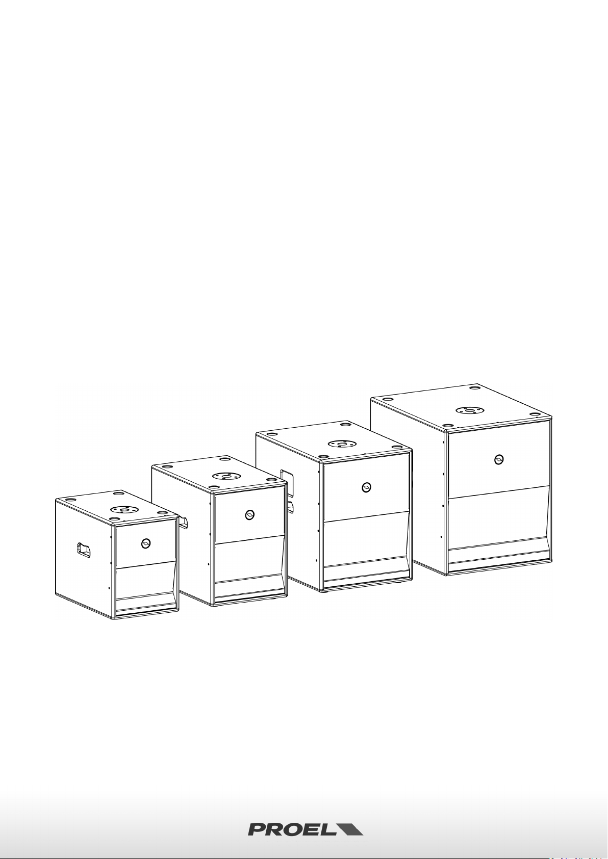
S series is a range of compact and powerful sub-woofers designed to complement PROEL full-range passive or
active speakers. The variety of size, power and SPL offered by the four S models provides the perfect low
extension solution for any speaker model available in the PROEL range.
All the S models feature high-excursion woofers in a Hybrid Band Pass configuration (HBP). This innovative
design provides a higher efficiency compared to direct radiation sub-woofers and, in addition, guarantees a
much better coupling of the tuning ducts with the external air, reducing the distortion and the air turbulence,
for a more defined sound and deep and punchy lows.
The new CLASS D amplifier modules with SMPS (Switch Mode Power Supply) can generate a massive amount
of continuous power in a compact, lightweight and reliable package. All the modules include a STEREO preamp section, 24dB/oct. crossover filters with selectable frequency and PHASE reverse switch.
The cabinets are built with 15 / 18mm plywood and finished with extra-durable polyurethane paint. They
feature two flush handles and four sturdy 75mm wheels for an easy transport (S15 and S18 only).
INSTRUCTIONS
6
Page 7

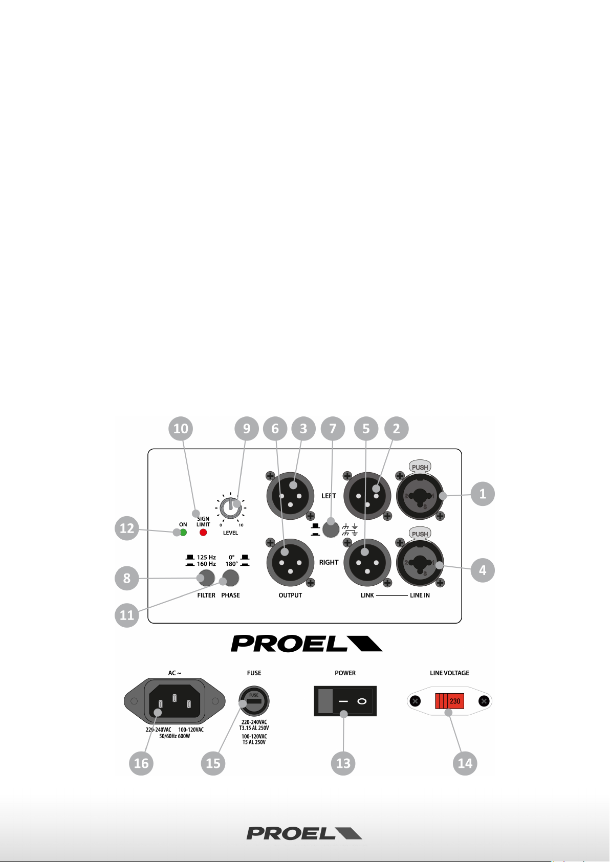
1. LINE IN (XLR-JACK combo input)
This is a female combo connector, which accepts an XLR or a JACK plug from almost any type of equipment
with a balanced or unbalanced output. The XLR input is wired as follows:
Pin 1 = shield or ground
Pin 2 = + positive or "hot"
Pin 3 = - negative or "cold"
The JACK input is wired as follows:
Tip = + positive or "hot"
Ring = - negative or "cold"
Sleeve = shield or ground
When connecting an unbalanced signal, wire them as follows:
Pin2 / Tip = + positive or "hot"
Pin 1-3 / Sleeve = shield or ground
NOTE: whenever possible, use always balanced cables. Unbalanced lines may also be used but they may result
in noise over long cable runs. In any case, avoid using a balanced cable for one channel and an unbalanced
one for the other.
2. LINK LEFT (XLR output balanced)
This is a male XLR connector connected in parallel with the respective line input, so the LINK is wired as the
input. Connect it to the input of another powered speaker to make an array.
3. OUT LEFT (XLR output balanced)
This is a male XLR connector providing a balanced line-level signal. This signal is filtered with a high-pass filter
to connect a satellite speaker. This output is wired as follows:
Pin 1 = shield or ground
Pin 2 = + positive or "hot"
Pin 3 = - negative or "cold"
4. INPUT RIGHT (combo XLR-JACK input)
Same as above. Use both inputs and outputs when connecting a stereo system to a single subwoofer (1 sub +
2 sat). In the case of a mono system (1 sub + 1 sat for each channel) you can use left or right input without
distinction.
5. LINK RIGHT (XLR output balanced)
This is a male XLR connector connected in parallel with the respective line input, so the LINK is wired as the
input. Connect it to the input of another powered speaker to make an array.
6. OUT RIGHT (XLR output balanced)
Same as above. Use both inputs and outputs when connecting a stereo system to a single subwoofer (1 sub +
2 sat). In the case of mono system (1 sub + 1 sat for each channel) you must use the same channel used for
input (left or right).
7. GND LIFT switch
This switch lifts the ground of the balanced audio inputs from the earth-ground of the amplifie r. If you have
HUM noise problems on one or more loudspeakers try to change the position of these switches (often all up
or all down for all the units in the system). Please note that to have an effect all cables must be balanced.
7
Page 8

8. FILTER switch
Use this switch to set the crossover frequency for the internal LOW PASS filter and for the HIGH PASS filter of
LEFT and RIGHT outputs. Choose the crossover frequency by your taste or music genre, or according to the
type of satellite connected.
The crossover frequencies vary between models: 125 / 160 Hz for S10A, 100 / 160 Hz for S12A and S15A, 80 /
125 Hz for S18A.
9. LEVEL control
Rotary level control: it attenuates the level of the signal sent to the subwoofer’s speaker. The attenuation
ranges from “0” fully closed (the signal is completely attenuated) to “10” fully open, nominal level (the signal
is not attenuated in any way, so is fed to the internal amplifier at the same level at which it arrives on input).
10. SIGN/CLIP indicator
GREEN LED illuminates to indicate the presence of the signal at the built-in amplifier input.
RED LED illuminates when the internal amplifier's output is limited. When this LED flashes continuously you
should reduce the input signal level.
11. PHASE 0° / 180° switch
This switch reverses the polarity of the subwoofer. Depending on the placement of the subwoofer relative to
the full-range satellite speakers, you can get a better low-frequency response in the room if you reverse the
polarity of the subwoofer’s signal. Listen in different positions of the venue to find which is the best sounding
setting.
NOTE: ALL SUBWOOFER SPEAKERS MUST BE HAVE THE SAME POLARITY. If you note a lack in lowest frequency
range using more than one subwoofer, probably you have one of them out-of-phase respect to the others. Be
always sure that all these switches are in same position.
12. ON indicator
GREEN LED: when lighted indicates that the amplifier has been turned on and AC power is available.
13. POWER switch
Speaker is "ON" when the switch is in the "I" position. Use this switch to set the speaker power to ON or OFF.
NOTE: When you shut down your equipment, turn off the speaker first. When powering up, turn on the
speaker last.
14. LINE VOLTAGE selector
This switch sets the AC voltage line of your country (usually it is set by factory and isn't necessary to change
it). The 115V setting is for mains line in the range of 100-120V~ and 230V setting is for mains line in the range
of 220-240V~.
WARNING: an incorrect setting of AC LINE VOLTAGE could damage seriously the internal electronics!
15. FUSE holder
Here is placed the mains protection fuse.
REPLACE THE PROTECTION FUSE ONLY WITH SAME TYPE AS SHOWN ON THE PRODUCT.
IF AFTER THE SUBSTITUTION, THE FUSE INTERRUPTS AGAIN THE APPARATUS WORKING, DO NOT
TRY AGAIN THEN CONTACT THE PROEL SERVICE CENTER.
8
Page 9

16. AC~ socket
S10A
S12A
S15A
S18A
System type
Hybrid Band Pass subwoofer
Hybrid Band Pass subwoofer
Hybrid Band Pass subwoofer
Hybrid Band Pass subwoofer
Loudspeaker
10’’ woofer with 2" VC
12’’ woofer with 3" VC
15’’ woofer with 3" VC
18’’ woofer with 4" VC
Amplifier Continuous Power
350 W
600 W
600 W
600 W
Amplifier Peak Power
700 W
1200 W
1200 W
1200 W
Frequency Response
46 Hz - 160 Hz
43 Hz - 160 Hz
40 Hz - 160 Hz
36 Hz - 140 Hz
Max SPL at 1m (peak)
119 dB
127 dB
129 dB
131 dB
Connectors
IN: 2 x NEUTRIK COMBO
IN: 2 x NEUTRIK COMBO
IN: 2 x NEUTRIK COMBO
IN: 2 x NEUTRIK COMBO
Controls
Level
Level
Level
Level
Power Supply
220-240 V~ or 100-120 V~
220-240 V~ or 100-120 V~
220-240 V~ or 100-120 V~
220-240 V~ or 100-120 V~
Consumption
600 W
600 W
600 W
600 W
Cabinet
15/18 mm plywood
15/18 mm plywood
15/18 mm plywood
15/18 mm plywood
Dimensions (W x H x D)
315x420x495mm
360x500x520mm
435x570x560mm
508x630x645mm
Weight
14 kg (30.8lb)
19 kg (41.9 lb)
26 kg (58 lb)
36 kg (79.4 lb)
Here’s where you plug in your speaker’s mains supply cord. You should always use the mains cord supplied
with the speaker. Be sure your speaker is turned off before you plug the mains supply cord into an electrical
outlet.
17. TECHNICAL SPECIFICATION
18. ACCESSORIES
OUT: 2 x NEUTRIK XLR-M
LINK: 2 x NEUTRIK XLR-M
GND lift
X-over frequency
Phase
50/60 Hz with LINE VOLTAGE
selector
Black anti-scratch paint
1.5 mm metal grille
2 handles
1 x pole socket
OUT: 2 x NEUTRIK XLR-M
LINK: 2 x NEUTRIK XLR-M
GND lift
X-over frequency
Phase
50/60 Hz with LINE VOLTAGE
selector
Black anti-scratch paint
1.5 mm metal grille
2 handles
1 x pole socket
OUT: 2 x NEUTRIK XLR-M
LINK: 2 x NEUTRIK XLR-M
GND lift
X-over frequency
Phase
50/60 Hz with LINE VOLTAGE
selector
Black anti-scratch paint
1.5 mm metal grille
2 handles
1 x pole socket
4 x 75 mm wheels
435x570x660mm (wheels)
OUT: 2 x NEUTRIK XLR-M
LINK: 2 x NEUTRIK XLR-M
GND lift
X-over frequency
Phase
50/60 Hz with LINE VOLTAGE
selector
Black anti-scratch paint
1.5 mm metal grille
2 handles
1 x pole socket
4 x 75 mm wheels
508x630x745mm (wheels)
KP210 - Adjustable speaker pole for speaker-subwoofer separation with terminal pieces Ø 35 mm. Supplied
with a bolt locking mechanism incorporating a steel pin for extra safety. Adjustment: 825 - 1320 mm.
9
Page 10

SOMMARIO - ITALIANO
TRATTAMENTO DEL DISPOSITIVO ELETTRICO OD ELETTRONICO A FINE VITA ..................................... 11
AVVERTENZE PER LA SICUREZZA .......................................................................................................... 11
IN CASO DI GUASTO ............................................................................................................................. 11
IMBALLAGGIO, TRASPORTO E RECLAMI .............................................................................................. 11
GARANZIE E RESI .................................................................................................................................. 11
MANUTENZIONE E LIMITAZIONI D’USO ............................................................................................... 12
ALIMENTAZIONE ................................................................................................................................... 12
CONFORMITÀ CE .................................................................................................................................. 12
INTRODUZIONE .................................................................................................................................... 13
DESCRIZIONE ........................................................................................................................................ 13
ISTRUZIONI ........................................................................................................................................... 13
1. INPUT LEFT (ingresso linea combo XLR-JACK) ........................................................................... 14
2. LINK LEFT (uscita bilanciata XLR) ............................................................................................... 14
3. OUT LEFT (uscita bilanciata XLR) ............................................................................................... 14
4. INPUT RIGHT (ingresso linea combo XLR-JACK) ........................................................................ 14
5. LINK RIGHT (uscita bilanciata XLR) ............................................................................................ 14
6. OUT RIGHT (uscita bilanciata XLR) ............................................................................................ 14
7. GND LIFT (interruttore sollevamento massa) ........................................................................... 14
8. FILTER (interruttore frequenza incrocio) ................................................................................... 15
9. LEVEL (controllo di livello) ......................................................................................................... 15
10. SIGN/CLIP (indicatore di segnale e clip limiter) ..................................................................... 15
11. PHASE 0° / 180° (interruttore inversione polarità) ................................................................ 15
12. ON (indicatore di accensione) ............................................................................................... 15
13. POWER (interruttore di accensione) ..................................................................................... 15
14. Selettore tensione di rete LINE VOLTAGE .............................................................................. 15
15. FUSE (portafusibili) ................................................................................................................ 15
16. AC~ (presa di alimentazione di rete) ..................................................................................... 16
17. SPECIFICHE TECNICHE ........................................................................................................... 16
18. ACCESSORI ............................................................................................................................. 16
Dimensioni Meccaniche ....................................................................................................................... 17
S10A ................................................................................................................................................. 17
S12A ................................................................................................................................................. 17
S15A ................................................................................................................................................. 18
S18A ................................................................................................................................................. 18
Configurazioni ...................................................................................................................................... 19
Connettori ............................................................................................................................................ 19
10
Page 11

TRATTAMENTO DEL DISPOSITIVO ELETTRICO OD ELETTRONICO A FINE VITA
Il marchio riportato sul prodotto o sulla documentazione indica che il prodotto non deve essere
smaltito con altri rifiuti domestici al termine del ciclo di vita. Per evitare eventuali danni all’ambiente si
invita l’utente a separare questo prodotto da altri tipi di rifiuti e di riciclarlo in maniera responsabile
per favorire il riutilizzo sostenibile delle risorse materiali. Gli utenti domestici sono invitati a contattare
il rivenditore presso il quale è stato acquistato il prodotto o l’ufficio locale preposto per tutte le
informazioni relative alla raccolta differenziata e al riciclaggio per questo tipo di prodotto. Gli utenti aziendali sono
invitati a contattare il proprio fornitore e verificare i termini e le condizioni del contratto di acquisto. Questo
prodotto non deve essere smaltito unitamente ad altri rifiuti commerciali.
AVVERTENZE PER LA SICUREZZA
• ATTENZIONE – Prima di utilizzare il prodotto, si prega di leggere attentamente le seguenti istruzioni per la sicurezza.
Prendere visione del manuale d’uso e conservarlo per successive consultazioni. Durante l’uso di un prodotto
elettrico devono essere sempre prese precauzioni di base onde evitare danni a cose o persone, incluse le seguenti:
• In presenza di bambini, controllare che il prodotto non rappresenti un pericolo.
• Posizionare l’apparecchio al riparo dagli agenti atmosferici e a distanza di sicurezza dall’acqua, dalla
pioggia e dai luoghi ad alto grado di umidità.
• Collocare o posizionare il prodotto lontano da fonti di calore quali radiatori, griglie di riscaldamento e
ogni altro dispositivo che produca calore.
• Evitare che qualsiasi oggetto o sostanza liquida entri all’interno del prodotto.
• Il prodotto deve essere connesso esclusivamente alla alimentazione elettrica delle caratteristiche
descritte nel manuale d’uso o scritte sul prodotto.
IN CASO DI GUASTO
• In caso di guasto o manutenzione questo prodotto deve essere ispezionato da personale qualificato quando:
• Sostanze liquide sono penetrate all’interno del prodotto.
• Il prodotto è caduto e si è danneggiato.
• Il prodotto non funziona normalmente esibendo una marcato cambio di prestazioni.
• Non intervenire sul prodotto. Rivolgersi a un centro di assistenza autorizzato Proel.
IMBALLAGGIO, TRASPORTO E RECLAMI
• L’imballo è stato sottoposto a test di integrità secondo la procedura ISTA 1A. Si raccomanda di controllare
il prodotto subito dopo l’apertura dell’imballo.
• Se vengono riscontrati danni informare immediatamente il rivenditore. Conservare quindi l’imballo
completo per permetterne l’ispezione.
• Proel declina ogni responsabilità per danni causati dal trasporto.
• Le merci sono vendute “franco nostra sede” e viaggiano sempre a rischio e pericolo del distributore.
• Eventuali avarie e danni dovranno essere contestati al vettore. Ogni reclamo per imballi manomessi
dovrà essere inoltrato entro 8 giorni dal ricevimento della merce.
GARANZIE E RESI
• I Prodotti Proel sono provvisti della garanzia di funzionamento e di conformità alle proprie specifiche,
come dichiarate dal costruttore.
• La garanzia di funzionamento è di 24 mesi dopo la data di acquisto. I difetti rilevati entro il periodo di garanzia
sui prodotti venduti, attribuibili a materiali difettosi o difetti di costruzione, devono essere tempestivamente
11
Page 12

segnalati al proprio rivenditore o distributore, allegando evidenza scritta della data di acquisto e descrizione
del tipo di difetto riscontrato. Sono esclusi dalla garanzia difetti causati da uso improprio o manomissione.
Proel SpA constata tramite verifica sui resi la difettosità dichiarata, correlata all’appropriato utilizzo, e l’effettiva
validità della garanzia; provvede quindi alla sostituzione o riparazione dei prodotti, declinando tuttavia ogni
obbligo di risarcimento per danni diretti o indiretti eventualmente derivanti dalla difettosità.
MANUTENZIONE E LIMITAZIONI D’USO
• Pulire il prodotto unicamente con un panno asciutto.
• I Prodotti Proel sono destinati esclusivamente ad un utilizzo specifico di tipo sonoro: segnali di ingresso di
tipo audio (20Hz-20kHz). Proel declina ogni responsabilità per danni a terzi causati da mancata
manutenzione, manomissioni, uso improprio o installazione non eseguita secondo le norme di sicurezza.
• Proel S.p.A. si riserva di modificare il prodotto e le sue specifiche senza preavviso.
• Proel S.p.A. declina ogni responsabilità per danni a terzi causati da mancata manutenzione, manomissioni, uso
improprio o installazione non eseguita secondo le norme di sicurezza e a regola d'arte.
ALIMENTAZIONE
• Il prodotto deve essere connesso esclusivamente alla alimentazione elettrica delle caratteristiche
descritte nel manuale d’uso o scritte sul prodotto.
• Se la spina in dotazione non combacia con la presa, rivolgersi ad un elettricista per far installare una presa appropriata.
• Quando si scollega l’apparato alla rete tenere saldamente sia la spina che la presa.
• Quando l’unità non viene utilizzata per un periodo prolungato, interrompere l’alimentazione estraendo la
spina dalla presa dell’alimentazione.
• Per evitare il danneggiamento del cavo d’alimentazione dell’apparato, non mettere in trazione il cavo
d’alimentazione e assicurarsi che questo non venga calpestato o schiacciato da oggetti pesanti.
• La spina di alimentazione viene utilizzata come dispositivo di disconnessione dalla rete elettrica e deve
rimanere facilmente raggiungibile.
CONFORMITÀ CE
• I Prodotti Proel sono conformi alla direttiva LVD 2014 / 35 / CE, secondo lo standard EN 60065.
• PROEL S.p.A dichiara che questo prodotto è conforme ai requisiti essenziali ed alle altre disposizioni
pertinenti stabilite dalla direttiva EMC 2014 / 30 / CE, secondo gli standard EN 55103-1 e EN 55103-2.
12
Page 13

INTRODUZIONE
Grazie per aver scelto un prodotto PROEL e della fiducia riposta nel nostro marchio, sinonimo di
professionalità, accuratezza, elevata qualità ed affidabilità. Tutti i nostri prodotti sono conformi alle
normative CE per utilizzazione continua in impianti di diffusione sonora.
DESCRIZIONE
La serie S è una linea di sub-woofers potenti e compatti progettati specificamente per un abbinamento
perfetto con i diffusori full-range PROEL attivi e passivi. La varietà di dimensioni, potenze e SPL offerte dai
cinque modelli della serie è in grado di fornire la perfetta estensione in bassa frequenza per qualunque
modello di diffusore presente nel catalogo PROEL.
Tutti i modelli S utilizzano woofer ad elevata escursione in configurazione Hybrid Band Pass (HBP). Questo
design innovativo è in grado di fornire un’efficienza maggiore rispetto a sub-woofer a radiazione diretta e,
inoltre, garantisce un miglior accoppiamento dei condotti di accordo con l’aria esterna, riducendo la distorsione
e le turbolenze, per un suono più definito ed una risposta alle basse frequenze profonda e dinamica.
I nuovi moduli di amplificazione in CLASSE D con alimentazione Switch Mode leggeri, compatti e affidabili
sono in grado di generare elevati livelli di potenza continua. Tutti i modelli includono una sezione di ingresso
STEREO, filtri di crossover a 24dB/ott. con frequenza selezionabile e selettore di FASE.
I cabinets sono costruiti in legno multistrato da 15/18mm e rivestiti con vernice poliuretanica extra resistente.
Includono due maniglie integrate e ruote da 75mm per il trasporto (S15 e S18).
ISTRUZIONI
13
Page 14

1. INPUT LEFT (ingresso linea combo XLR-JACK)
Connettore combinato che accetta un XLR o un JACK maschio da praticamente tutti gli apparecchi con un
livello di uscita linea bilanciato o sbilanciato. Le terminazioni dell'ingresso XLR sono:
Pin 1 = schermo o massa
Pin 2 = + positivo o "caldo"
Pin 3 = - negativo o "freddo"
Le terminazioni dell'ingresso JACK sono le seguenti:
Tip (punta) = + positivo o "caldo"
Ring (anello) = - negativo o "freddo"
Sleeve (manicotto) = schermo o massa
Quando si collega un segnale sbilanciato, sono le seguenti:
Pin2 / Tip (punta) = + positivo o "caldo"
Pin 1-3 / Sleeve (manicotto) = schermo o massa
NOTA: Qualora possibile, usare sempre cavi bilanciati. Cavi sbilanciati possono essere ugualmente usati ma
potrebbero dare problemi di rumore se molto lunghi. In ogni caso, evitate di usare un cavo bilanciato per un
canale e uno sbilanciato per l’altro.
2. LINK LEFT (uscita bilanciata XLR)
Connettore XLR maschio connesso in parallelo con il rispettivo connettore LINE IN, per cui il LINK è terminato
come il LINE IN. Può essere collegato ad altri altoparlanti amplificati per formare un sistema di rinforzo
sonoro multiplo.
3. OUT LEFT (uscita bilanciata XLR)
Connettore XLR che fornisce un segnale di linea bilanciato. Questo segnale è filtrato con un filtro passa alto
per connettere un diffusore satellite. Le terminazioni di queste uscite sono le seguenti:
Pin 1 = schermo o massa
Pin 2 = + positivo o "caldo"
Pin 3 = - negativo o "freddo"
4. INPUT RIGHT (ingresso linea combo XLR-JACK)
Vedi sopra. Usare entrambi gli ingressi e le uscite quando si collega un sistema stereo ad un singolo
subwoofer (1sub + 2 sat). Nel caso di un sistema mono (1sub + 1 sat per ogni canale) si può usare l'ingresso
LEFT (sinistro) o RIGHT (destro) senza distinzione.
5. LINK RIGHT (uscita bilanciata XLR)
Connettore XLR maschio connesso in parallelo con il rispettivo connettore LINE IN, per cui il LINK è terminato
come il LINE IN. Può essere collegato ad altri altoparlanti amplificati per realizzare un sistema di rinforzo
sonoro multiplo.
6. OUT RIGHT (uscita bilanciata XLR)
Vedi sopra. Usare entrambi gli ingressi e le uscite quando si collega un sistema stereo ad un singolo
subwoofer (1sub + 2 sat). Nel caso di un sistema mono (1sub + 1 sat per ogni canale) è necessario usare la
stessa uscita usata per il segnale in ingresso LEFT (sinistro) o RIGHT (destro).
7. GND LIFT (interruttore sollevamento massa)
Questo interruttore solleva la massa degli ingressi audio bilanciati dalla massa-terra dell'amplificatore. Se si
hanno problemi di ronzio su uno o più altoparlanti provare a cambiare la posizione di questi interruttori:
14
Page 15

perché abbiano effetto spesso occorre siano tutti su o tutti giù per tutti gli amplificatori e che tutti i cavi siano
bilanciati.
8. FILTER (interruttore frequenza di crossover)
Usate questo interruttore per impostare la frequenza di incrocio del filtro crossover interno e di quello delle
uscite OUT LEFT e RIGHT. Scegliere la frequenza di incrocio in base al proprio gusto o al genere musicale,
oppure a seconda del tipo di satellite utilizzato. La frequenza di crossover varia tra i modelli: 125 / 160 Hz per
S10A, 100 / 160 Hz per S12A e S15A, 80 / 125 Hz per S18A.
9. LEVEL (controllo di livello)
Controllo di livello rotativo: attenua il livello del segnale inviato all'altoparlante del subwoofer. L'attenuazione
varia tra completamente chiuso “0” a completamente aperto “10” o livello nominale (il segnale non è
attenuato in nessun modo e viene inviato all'amplificatore interno allo stesso livello con cui arriva
all'ingresso).
10. SIGN/CLIP (indicatore di segnale e clip limiter)
LED VERDE, si accende per indicare la presenza del segnale all'ingresso dell'amplificatore interno.
LED ROSSO, si accende quando l'uscita dell'amplificatore interno è limitata. Quando questo LED lampeggia in
modo continuo è consigliabile ridurre il segnale di ingresso.
11. PHASE 0° / 180° (interruttore inversione polarità)
Questo interruttore inverte la polarità del subwoofer. A seconda della posizione del subwoofer rispetto ai
diffusori satellite si può ottenere una migliore risposta in bassa frequenza se si inverte la polarità del segnale
che pilota il subwoofer. Ascoltando in differenti punti della sala sperimentate quale impostazione di questo
interruttore suona meglio.
NOTA: TUTTI GLI ALTOPARLANTI SUBWOOFER DEVONO AVERE LA MEDESIMA POLARITÀ. Se si nota una
insufficienza di frequenze basse usando più di un subwoofer, probabilmente si è impostato un subwoofer
invertito rispetto agli altri. Assicurarsi sempre che tutti questi interruttori siano nella stessa posizione.
12. ON (indicatore di accensione)
LED VERDE: quando acceso indica che l'altoparlante è stato acceso e l'alimentazione AC è disponibile.
13. POWER (interruttore di accensione)
L'altoparlante è acceso "ON" quando l'interruttore è nella posizione "I". Agite su questo tasto per accendere
o spegnere l'altoparlante.
NOTA: Quando si spegne l'impianto sonoro, spegnere per primi gli altoparlanti. Quando si accende l'impianto
sonoro, accendere gli altoparlanti per ultimi.
14. Selettore tensione di rete LINE VOLTAGE
Questo selettore imposta la tensione di rete della linea elettrica del vostro paese (tipicamente è già
impostato dalla fabbrica e non è necessario cambiarlo). L'impostazione 115V è per le linee elettriche da 100120V~ e l'impostazione 230V è per le linee elettriche da 210-240V~.
ATTENZIONE una sbagliata impostazione della linea elettrica AC LINE VOLTAGE può danneggiare
seriamente l'amplificatore interno.
15. FUSE (portafusibili)
In questo vano è inserito il fusibile di protezione principale di rete.
15
Page 16

RIMPIAZZARE IL FUSIBILE DI PROTEZIONE ESCLUSIVAMENTE CON UN FUSIBILE CON LE MEDESIME
S10A
S12A
S15A
S18A
Sistema
Subwoofer Hybrid Band Pass
Subwoofer Hybrid Band Pass
Subwoofer Hybrid Band Pass
Subwoofer Hybrid Band Pass
Altoparlante
10’’ woofer - 2" VC
12’’ woofer - 3" VC
15’’ woofer - 3" VC
18’’ woofer - 4" VC
Potenza amplif. (continua)
350 W
600 W
600 W
600 W
Potenza amplif. (picco)
700 W
1200 W
1200 W
1200 W
Risposta in Frequenza
46 Hz - 160 Hz
43 Hz - 160 Hz
40 Hz - 160 Hz
36 Hz - 140 Hz
SPL max a 1m (picco)
119 dB
127 dB
129 dB
131 dB
Connettori
IN: 2 x NEUTRIK COMBO
IN: 2 x NEUTRIK COMBO
IN: 2 x NEUTRIK COMBO
IN: 2 x NEUTRIK COMBO
Controlli
Level
Level
Level
Level
Tensione alim. di rete
220-240 V~ o 100-120 V~
220-240 V~ o 100-120 V~
220-240 V~ o 100-120 V~
220-240 V~ o 100-120 V~
Consumo massimo
600 W
600 W
600 W
600 W
Costruzione Cabinet
Legno multistrato 15/18 mm
Legno multistrato 15/18 mm
Legno multistrato 15/18 mm
Legno multistrato 15/18 mm
Dimensioni (L x A x P)
315x420x495mm
360x500x520mm
435x570x560mm
508x630x645mm
Peso
14 kg
19 kg
26.3 kg
36 kg
CARATTERISTICHE RIPORTATE SUL PRODOTTO.
SE DOPO LA SOSTITUZIONE, IL FUSIBILE INTERROMPE NUOVAMENTE IL FUNZIONAMENTO DELL'APPARATO,
NON INSISTERE E CONTATTARE IL SERVIZIO ASSISTENZA PROEL.
16. AC~ (presa di alimentazione di rete)
Inserire in questa presa il cavo di alimentazione di rete, utilizzando esclusivamente il cavo in dotazione.
Accertarsi che l'altoparlante sia spento prima di collegarlo alla rete.
17. SPECIFICHE TECNICHE
18. ACCESSORI
OUT: 2 x NEUTRIK XLR-M
LINK: 2 x NEUTRIK XLR-M
GND lift
X-over frequency
Phase
50/60 Hz con selezione LINE
VO LTAGE
Vernice nera antigraffio
Rete metallica 1.5 mm
2 maniglie
1 flangia per supporto
OUT: 2 x NEUTRIK XLR-M
LINK: 2 x NEUTRIK XLR-M
GND lift
X-over frequency
Phase
50/60 Hz con selezione LINE
VO LTAGE
Vernice nera antigraffio
Rete metallica 1.5 mm
2 maniglie
1 flangia per supporto
OUT: 2 x NEUTRIK XLR-M
LINK: 2 x NEUTRIK XLR-M
GND lift
X-over frequency
Phase
50/60 Hz con selezione LINE
VO LTAGE
Vernice nera antigraffio
Rete metallica 1.5 mm
2 maniglie
1 flangia per supporto
4 ruote 75 mm
435x570x660mm (ruote)
OUT: 2 x NEUTRIK XLR-M
LINK: 2 x NEUTRIK XLR-M
GND lift
X-over frequency
Phase
50/60 Hz con selezione LINE
VO LTAGE
Vernice nera antigraffio
Rete metallica 1.5 mm
2 maniglie
1 flangia per supporto
4 ruote 75 mm
508x630x745mm (ruote)
KP210 - Supporto distanziatore cassa-subwoofer regolabile in acciaio con terminali Ø 35mm. Dotato di
meccanismo di chiusura a vite con pin di sicurezza in acciaio. Regolazione: 825 - 1320 mm.
16
Page 17

Mechanical Dimensions – Dimensioni Meccaniche
S10A
S12A
17
Page 18

S15A
S18A
18
Page 19

Configurations – Configurazioni
Connectors - Connettori
19
Page 20

PROEL S.p.A.
(World Headquarters - Factory)
Via alla Ruenia 37/43
64027 Sant’Omero (Te) – Italy
Tel: +39 0861 81241
Fax: +39 0861 887862
www.proel.com
20
 Loading...