How it Works
Log In / Sign Up
Buy Points
How it Works
FAQ
Contact Us
Questions and Suggestions
Users
Proel
Loading...
P
PLST15H
PLST15HDX
2
PLST50
2
PLSUSX
PLW18W
PLW36W
2
PLWIN60C
PMA120
PPCASE04
PPCASE12W
PR10AL
2
PR10ALBI
PR10PL
2
PR10PLB
PR20AL
PR20ALBI
PR30PL
PREW
prl1400
5
PRL250
prl600
4
prl950
4
PRO100BK
PRO100CR
PROEVAC EVO EV PROM5Z
PRO EVAC SYSTEM
PRONET
PROX
PSA240
PSU110
PSW1800
PSW2600
PXCOVER08N
R
R88
R88L
Raptor
RB13
RM100
RM100G
RM100H
2
RM100KIT
RM100L
RM100M
RM200
RM2000TR
RM300
RM3000TR
RMW10
RMW1000
3
RMW1000H
3
RMW1000M
4
RMW1H
RMW1M
RMW8
RMW821
RSM100BK
RSM240
RSM300
RXTOUR
2
S
S10A
2
S10P
2
S12A
2
S15A
2
S15P
2
S18A
2
S18P
2
SCOOPSCAN 250 A SCARICA
SESSION4
2
Session6 2.1 column array set
SG CLSPOT
SG FLASHLED
SMART plus
SMART V plus
SMOKE MACHINE 1200W
SOURCE
SPIDER 575 PLCP575
SPL100
SPL150
SPL152
SPL250
SPL253
SPLIT100
SPOT 1000 ECLIPSE
S Series
2
STARPOINT 1200
Stone
STRAP100BK
STRING AND WIND
STRING AND WIND INSTRUMENT
Strobo 500
SW110
2
SW110A
SW110A V2
SW110P
SW115
SW115A
SW115HA
3
SW115P
2
SW118A
SW118H
3
Loading...
Loading...
Nothing found
RMW1000M
User Manual
32 pgs
539.99 Kb
0
User Manual [en, it, de, fr, es]
82 pgs
920.02 Kb
0
USER’S MANUAL
32 pgs
455.76 Kb
0
USER’S MANUAL
30 pgs
1.01 Mb
0
Table of contents
Loading...
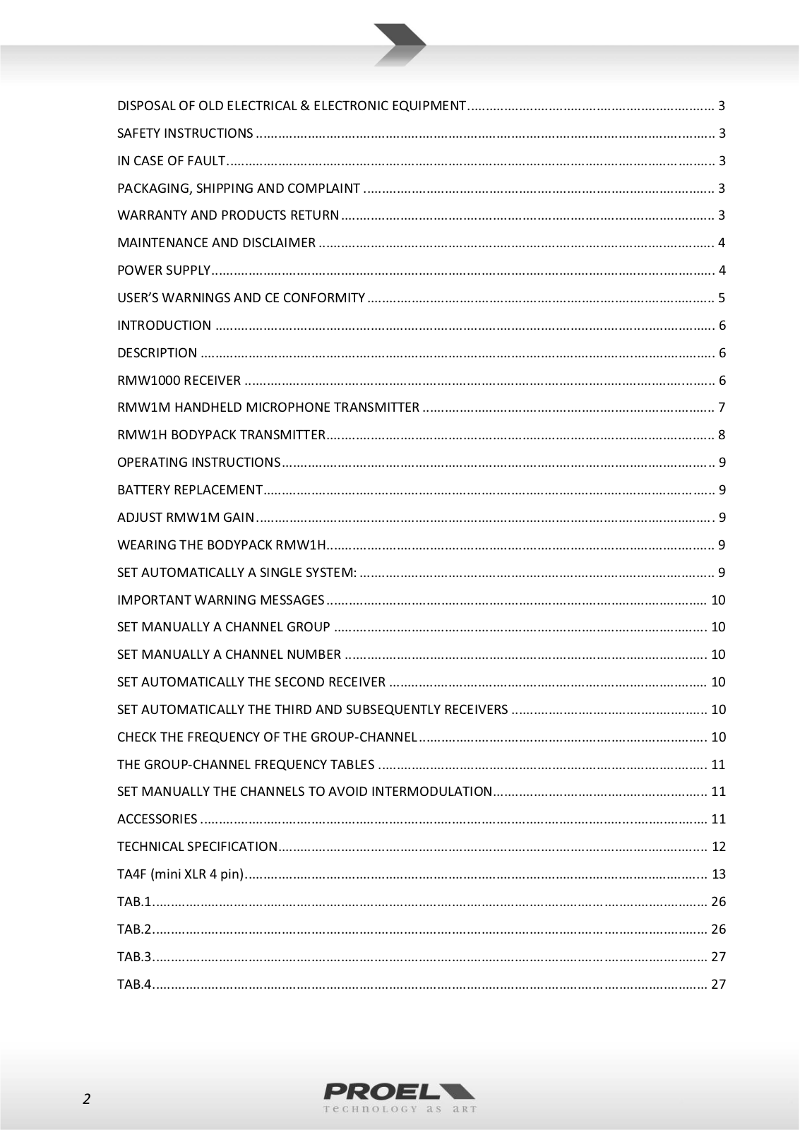
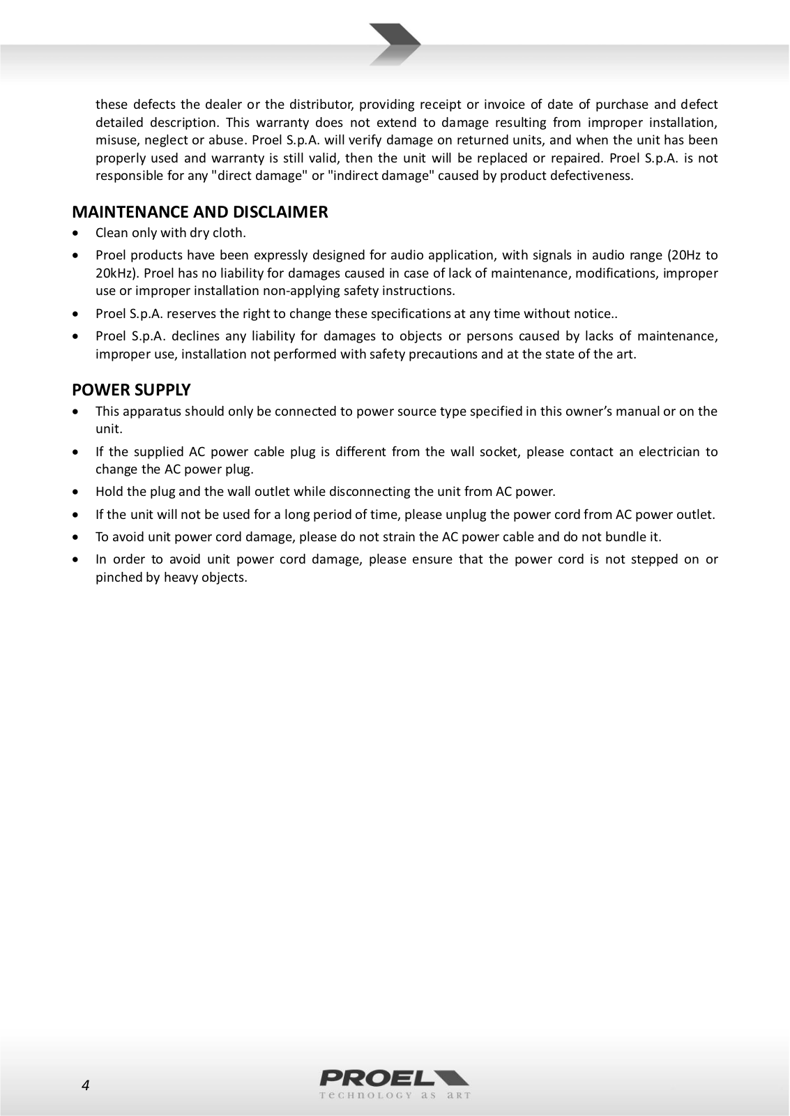
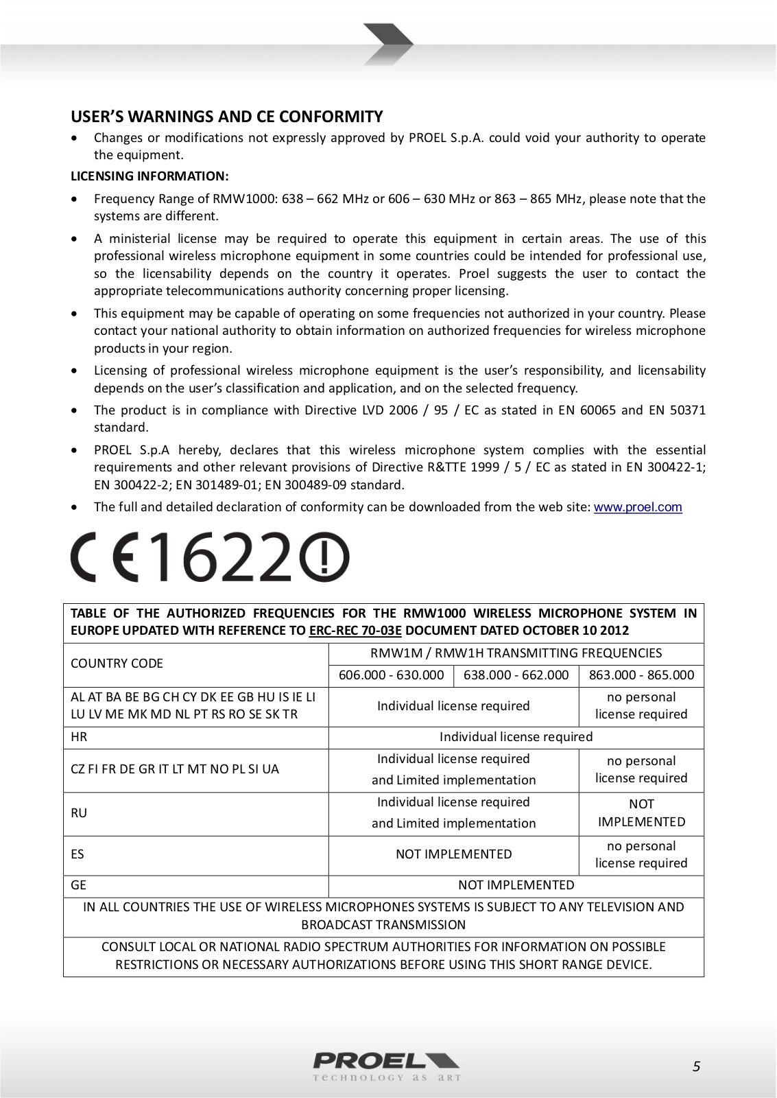
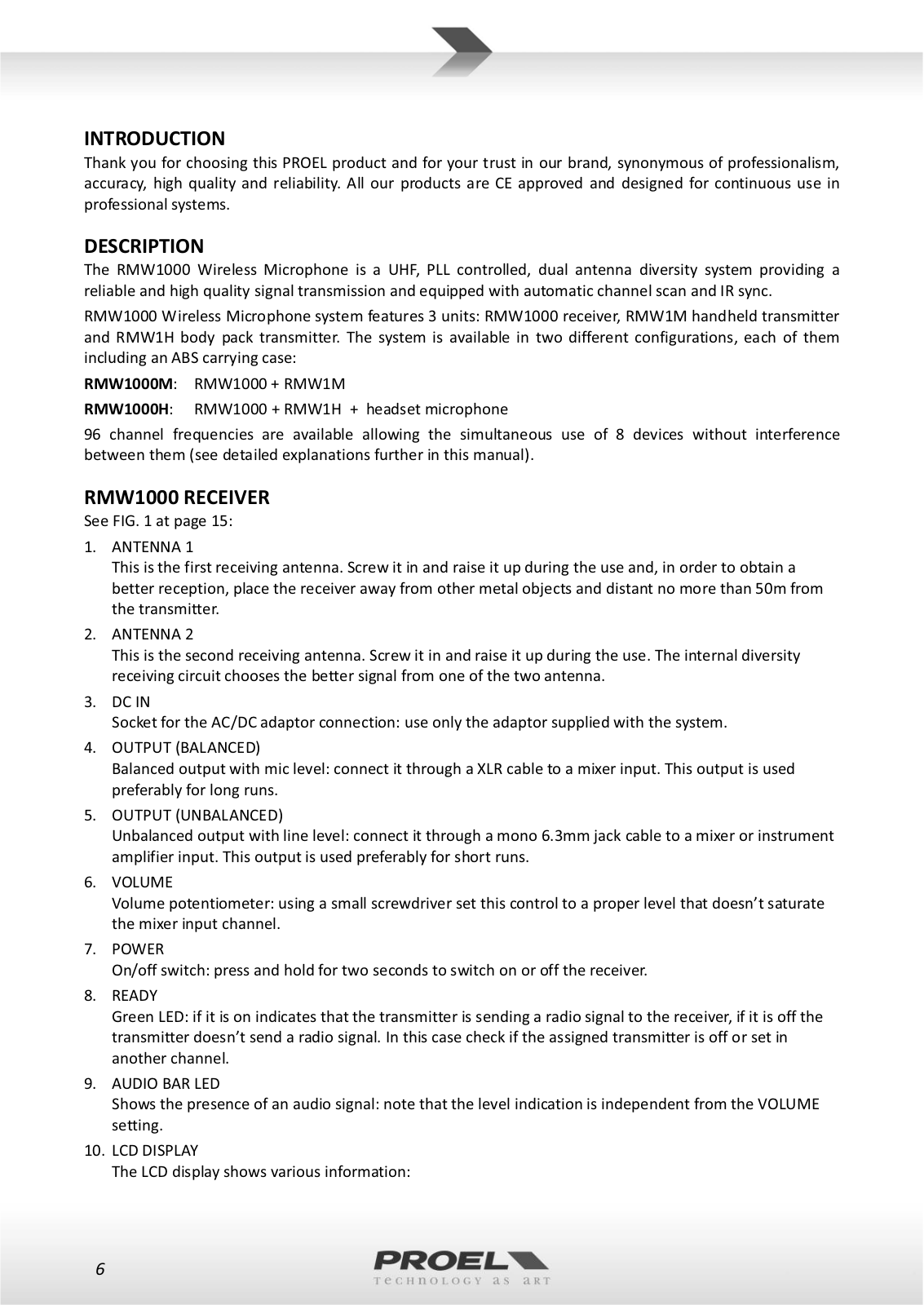
Proel RMW1000M, RMW1000H USER’S MANUAL
...
Proel USER’S MANUAL
Download
Specifications and Main Features
Frequently Asked Questions
User Manual
Download
Loading...
+
hidden pages
Unhide
You need points to download manuals.
1 point = 1 manual.
You can buy points or you can get point for every manual you upload.
Buy points
Upload your manuals
 Loading...