

RMW1000
Wireless Microphone System
USER’S MANUAL
96MAN00082-REV.01/17
ITALIANO
ENGLISH

2
DISPOSAL OF OLD ELECTRICAL & ELECTRONIC EQUIPMENT 3
SAFETY INSTRUCTIONS 3
IN CASE OF FAULT 3
PACKAGING, SHIPPING AND COMPLAINT 3
WARRANTY AND PRODUCTS RETURN 4
MAINTENANCE AND DISCLAIMER 4
POWER SUPPLY 4
USER’S WARNINGS AND CE CONFORMITY 5
INTRODUCTION 6
DESCRIPTION 6
RMW1000 RECEIVER 6
RMW1M HANDHELD MICROPHONE TRANSMITTER 7
RMW1H BODYPACK TRANSMITTER 8
OPERATING INSTRUCTIONS 8
BATTERY REPLACEMENT 8
WEARING THE BODYPACK RMW1H 9
SET AUTOMATICALLY A SINGLE SYSTEM 9
SET MANUALLY A CHANNEL GROUP 9
SET MANUALLY A CHANNEL NUMBER 9
SET AUTOMATICALLY THE SECOND RECEIVER 9
SET AUTOMATICALLY THE THIRD AND SUBSEQUENTLY RECEIVERS 9
CHECK THE FREQUENCY OF THE GROUP-CHANNEL 10
THE GROUP-CHANNEL FREQUENCY TABLES 10
SET MANUALLY THE CHANNELS TO AVOID INTERMODULATION 10
ACCESSORIES 10
TIPS TO IMPROVE WIRELESS SYSTEM PERFORMANCE 11
TECHNICAL SPECIFICATION 11
TA3F (mini XLR 3 pin) 13

3
DISPOSAL OF OLD ELECTRICAL & ELECTRONIC EQUIPMENT
This marking shown on the product or its literature, indicates that it should not be disposed with
other household wastes at the end of its working life. To prevent possible harm to the enviroment
or human health from uncontrolled waste disposal, please separate this from other types of
wastes and recycle it responsibly to promote the sustainable reuse of material resources.
Household users should contact either the retailer where they purchased this product, or their
local government office, for details of where and how they can take this item for environmentally safe
recycling. Business users should contact their supplier and check the terms and conditions of the purchase
contract. This product should not be mixed with other commercial wastes for disposal.
SAFETY INSTRUCTIONS
• CAUTION - Before using this product read carefully the following safety instructions. Take a look of this
manual entirely and preserve it for future reference. When using any electric product, basic precautions
should always be taken, including the following:
• To reduce the risk, close supervision is necessary when the product is used near children.
• Protect the apparatus from atmospheric agents and keep it away from water, rain and high humidity
places.
• This product should be site away from heat sources such as radiators, lamps and any other device that
generate heat.
• Care should be taken so that objects and liquids do not go inside the product..
• The product should be connected to a power supply only of the type described on the operating
instructions or as marked on the product.
IN CASE OF FAULT
• In case of fault or maintenance this product should be inspected only by qualified service personnel
when:
Liquids have spilled inside the product.
The product has fallen and been damaged.
The product does not appear to operate normally or exhibits a marked change in performance.
• Do not operate on the product, it has no user-serviceable parts inside.
• Refer servicing to an authorized maintenance centre.
PACKAGING, SHIPPING AND COMPLAINT
• This unit package has been submitted to ISTA 1A integrity tests. We suggest you control the unit
conditions immediately after unpacking it.
• If any damage is found, immediately advise the dealer. Keep all unit packaging parts to allow inspection.
• Proel is not responsible for any damage that occurs during shipment..
• Products are sold “delivered ex warehouse” and shipment is at charge and risk of the buyer.
• Possible damages to unit should be immediately notified to forwarder. Each complaint for manumitted
package should be done within eight days from product receipt.

4
WARRANTY AND PRODUCTS RETURN
• Proel products have operating warranty and comply their specifications, as stated by manufacturer..
• Proel warrants all materials, workmanship and proper operation of this product for a period of two years
from the original date of purchase. If any defects are found in the materials or workmanship or if the
product fails to function properly during the applicable warranty period, the owner should inform about
these defects the dealer or the distributor, providing receipt or invoice of date of purchase and defect
detailed description. This warranty does not extend to damage resulting from improper installation,
misuse, neglect or abuse. Proel S.p.A. will verify damage on returned units, and when the unit has been
properly used and warranty is still valid, then the unit will be replaced or repaired. Proel S.p.A. is not
responsible for any "direct damage" or "indirect damage" caused by product defectiveness.
MAINTENANCE AND DISCLAIMER
• Clean only with dry cloth.
• Proel products have been expressly designed for audio application, with signals in audio range (20Hz to
20kHz). Proel has no liability for damages caused in case of lack of maintenance, modifications, improper
use or improper installation non-applying safety instructions.
• Proel S.p.A. reserves the right to change these specifications at any time without notice..
• Proel S.p.A. declines any liability for damages to objects or persons caused by lacks of maintenance,
improper use, installation not performed with safety precautions and at the state of the art.
POWER SUPPLY
• This apparatus should only be connected to power source type specified in this owner’s manual or on the
unit.
• If the supplied AC power cable plug is different from the wall socket, please contact an electrician to
change the AC power plug.
• Hold the plug and the wall outlet while disconnecting the unit from AC power.
• If the unit will not be used for a long period of time, please unplug the power cord from AC power outlet.
• To avoid unit power cord damage, please do not strain the AC power cable and do not bundle it.
• In order to avoid unit power cord damage, please ensure that the power cord is not stepped on or
pinched by heavy objects.
5
USER’S WARNINGS AND CE CONFORMITY
TABL
E OF THE AUTHORIZED
FREQUEN
CIES FOR THE
RMW10
00 WIRELESS MICROPHONE
SYSTEM IN
RMW1M
/ RM
W1H
TRANSMITTING FREQUENCIES
551 -581
AL AT BA BE BG CH CY DK EE GB HU IS IE LI
Individual license required
Individual license required
ES NOT IMPLEMENTED
GE NOT IMPLEMENTED
IN
ALL C
OUNTR
IES THE USE OF WIRELESS MICROPHONES SYSTEMS IS SUBJECT TO ANY TELEVISION AND
CONSULT LOCAL OR NATIONAL RADIO SPECTRUM AUTHORITIES FOR INFORMATION ON POSSIBLE
• Changes or modifications not expressly approved by PROEL S.p.A. could void your authority to operate
the equipment.
LICENSING INFORMATION:
• Frequency Range of RMW1000: 551 – 581 MHz.
• A ministerial license may be required to operate this equipment in certain areas. The use of this
professional wireless microphone equipment in some countries could be intended for professional use,
so the licensability depends on the country it operates. Proel suggests the user to contact the
appropriate telecommunications authority concerning proper licensing.
• This equipment may be capable of operating on some frequencies not authorized in your country. Please
contact your national authority to obtain information on authorized frequencies for wireless microphone
products in your region.
• Licensing of professional wireless microphone equipment is the user’s responsibility, and licensability
depends on the user’s classification and application, and on the selected frequency.
• The product is in compliance with Directive LVD 2006 / 95 / EC as stated in EN 60065 and EN 50371
standard.
• PROEL S.p.A hereby, declares that this wireless microphone system complies with the essential
requirements and other relevant provisions of Directive 2014 / 53 / UE as stated in EN 300422-1; EN
300422-2; EN 301489-01; EN 300489-09 standard.
• The full and detailed declaration of conformity can be downloaded from the web site:
EUROPE UPDATED WITH REFERENCE TO ERC-REC 70-03E DOCUMENT DATED OCTOBER 10 2012
COUNTRY CODE
LU LV ME MK MD NL PT RS RO SE SK TR HR
CZ FI FR DE GR IT LT MT NO PL SI UA
RU
BROADCAST TRANSMISSION
Individual license required
and Limited implementation
and Limited implementation
www.proel.com
RESTRICTIONS OR NECESSARY AUTHORIZATIONS BEFORE USING THIS SHORT RANGE DEVICE.

6
INTRODUCTION
Thank you for choosing this PROEL product and for your trust in our brand, synonymous of professionalism,
accuracy, high quality and reliability. All our products are CE approved and designed for continuous use in
professional systems.
DESCRIPTION
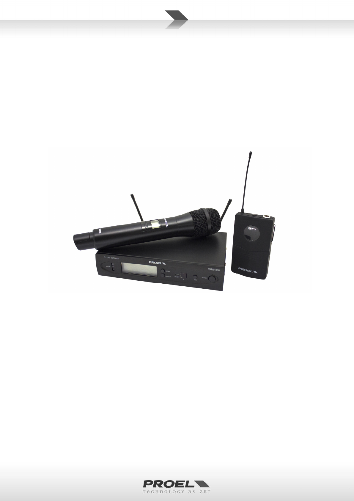
The RMW1000 Wireless Microphone is a UHF, PLL controlled, dual antenna diversity system providing a
reliable and high quality signal transmission and equipped with automatic channel scan and IR sync.
RMW1000 Wireless Microphone system features 3 units: RMW1000 receiver, RMW1M handheld transmitter
and RMW1H body pack transmitter. The system is available in two different configurations, each of them
including an ABS carrying case:
RMW1000M: RMW1000 + RMW1M
RMW1000H: RMW1000 + RMW1H + headset microphone
121 channel frequencies are available allowing the simultaneous use of 6 devices without interference
between them (see detailed explanations further in this manual).
RMW1000 RECEIVER
See FIG. 1 at page 15:
1. ANTENNA 1
This is the first receiving antenna. Screw it in and raise it up during the use and, in order to obtain a
better reception, place the receiver away from other metal objects and distant no more than 50m from
the transmitter.
2. ANTENNA 2
This is the second receiving antenna. Screw it in and raise it up during the use. The internal diversity
receiving circuit chooses the better signal from one of the two antenna.
3. DC IN
Socket for the AC/DC adaptor connection: use only the adaptor supplied with the system.
4. OUTPUT (BALANCED)
Balanced output with mic level: connect it through a XLR cable to a mixer input. This output is used
preferably for long runs.
5. OUTPUT (UNBALANCED)
Unbalanced output with line level: connect it through a mono 6.3mm jack cable to a mixer or instrument
amplifier input. This output is used preferably for short runs.
6. VOLUME
Volume potentiometer: using a small screwdriver set this control to a proper level that doesn’t saturate
the mixer input channel.
7. POWER
On/off switch: press and hold for two seconds to switch on or off the receiver.
8. READY
Green LED: if it is on indicates that the transmitter is sending a radio signal to the receiver, if it is off the
transmitter doesn’t send a radio signal. In this case check if the assigned transmitter is off or set in
another channel.
9. AUDIO BAR LED
Shows the presence of an audio signal: note that the level indication is independent from the VOLUME
setting.
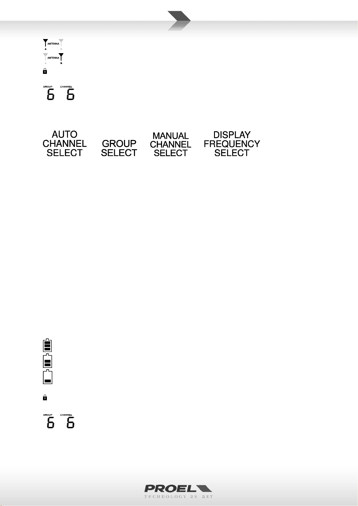
10. LCD DISPLAY
The LCD display shows various information:
7
Antenna A is working and receives the radio signal.
Antenna B is working and receives the radio signal.
The receiver is locked and the buttons have no effect. Press “menu” and “select” together to lock or
unlock the receiver. Locking the receiver and the transmitters prevents unwanted setting changes.
Typically the LCD shows the channel actually in use (see further in this manual for detailed
operating instructions about channel setting and frequency visualization).
11. MENU BUTTON
Pressing this button you can scroll through the menu options:
After pressing it you have 5 second to press the “SELECT” button for choosing one option. If “SELECT”
button is not pressed, the receiver goes back to normal operation (see further on this manual for detailed
operations).
12. SELECT
Pressing this button you can activate or change a value of the correspondent menu option. After pressing
it you have 5 second to press again the “SELECT” button to choose the next option or value. If “SELECT”
button is not pressed, the receiver goes back to normal operation (see further on this manual for detailed
operations).
13. ASC
Pressing this button the receiver sends the channel setting to the microphone or bodypack transmitter
through the IR port.
14. IR
This is the infrared port to send the channel setting.
RMW1M HANDHELD MICROPHONE TRANSMITTER
See FIG. 2 and FIG. 5 at page 16:
15. MICROPHONE GRID
The grid protects the microphone capsule and includes a pop filter. The microphone capsule is dynamic
with a cardioid unidirectional pattern.
16. LCD DISPLAY STATUS LED
The LCD display shows various information:
the batteries are fully charged and you have 6-8 hours of working operation using alkaline batteries.
the batteries are half charged and you have 2-6 hours of working operation using alkaline batteries.
the batteries are almost discharged and you have 0-2 hours of working operation using alkaline
batteries: batteries replacement is suggested as soon as possible.
The transmitter is locked and the buttons have no effect: press “mute” and “select” together to lock
or unlock the transmitter. Locking the transmitter and the receiver prevents unwanted setting changes.
Typically the LCD shows the channel actually in use (see further on this manual for detailed
operating instructions about channel setting).

8
17. STATUS LED
This LED shows the status of the transmitter:
OFF: the transmitter is off or is on but muted.
GREEN: the transmitter is on and operative.
18. IR
After removing the battery cover, you can access the infrared port for receiving the channel setting.
19. BATTERY COMPARTMENT
20. ON – OFF – MUTE
Press and hold this button for 3 seconds and you turn on the transmitter ( LED GREEN ). If you press again
the button the transmitter goes in mute ( LED GREEN OFF ). If you press the button for 3 seconds the
transmitter goes off.
RMW1H BODYPACK TRANSMITTER
See FIG. 8 at page 16:
21. ANTENNA
This is the transmitting antenna: do not force, disconnect or try to replace with another one.
22. BATTERIES COVER
Sliding down the lower part of the bodypack you can access the battery inlet and the IR receiver sensor.
23. AUDIO INPUT
T3AF mini XLR input socket to connect the supplied microphone or other microphone.
24. ON – OFF – MUTE BUTTON
Press and hold this button for 3 seconds and you turn on the transmitter ( LED GREEN ). If you press again
the button the transmitter goes in mute ( LED ORANGE ). Press the button for 3 seconds to switch off the
transmitter.
25. STATUS LED
This LED shows the status of the transmitter:
OFF: the transmitter if turned off .
GREEN: the transmitter is on and operative.
ORANGE: the transmitter is on but muted.
26. IR
After removing the battery cover, you can access the infrared port for receiving the channel setting.
27. GAIN SWITCH
With this switch it’s possible to set the gain of the bodypack microphone: set it at 0dB for speaking
voices and at -10dB for singing voices.
OPERATING INSTRUCTIONS
BATTERY REPLACEMENT
For the Battery replacement use always 2x 1.5V AA size LITHIUM or ALKALINE type for the best
performances. You can use also rechargeable batteries but in this case the operating time is shorter. Good
quality ALKALINE batteries guarantee an operating time of about 8 hour.
To replace the batteries on the RMW1M handheld microphone follow the instructions on FIG.3 and 4,
respecting always the polarity marked inside the battery inlet.
To replace the batteries on the RMW1H bodypack microphone follow the instructions on FIG.8 and 9,
respecting always the polarity marked inside the battery inlet.
Always remember to remove the batteries if you don’t use the microphone for a long period of time: this will
avoid the corrosion of the battery contacts.
9
WEARING THE BODYPACK RMW1H
As show in FIG.10 it’s possible to wear the bodypack to a belt, strap or dress vertically or horizontally and
simply turning the spring on the other side, in any case be careful don’t fold or pull the antenna.
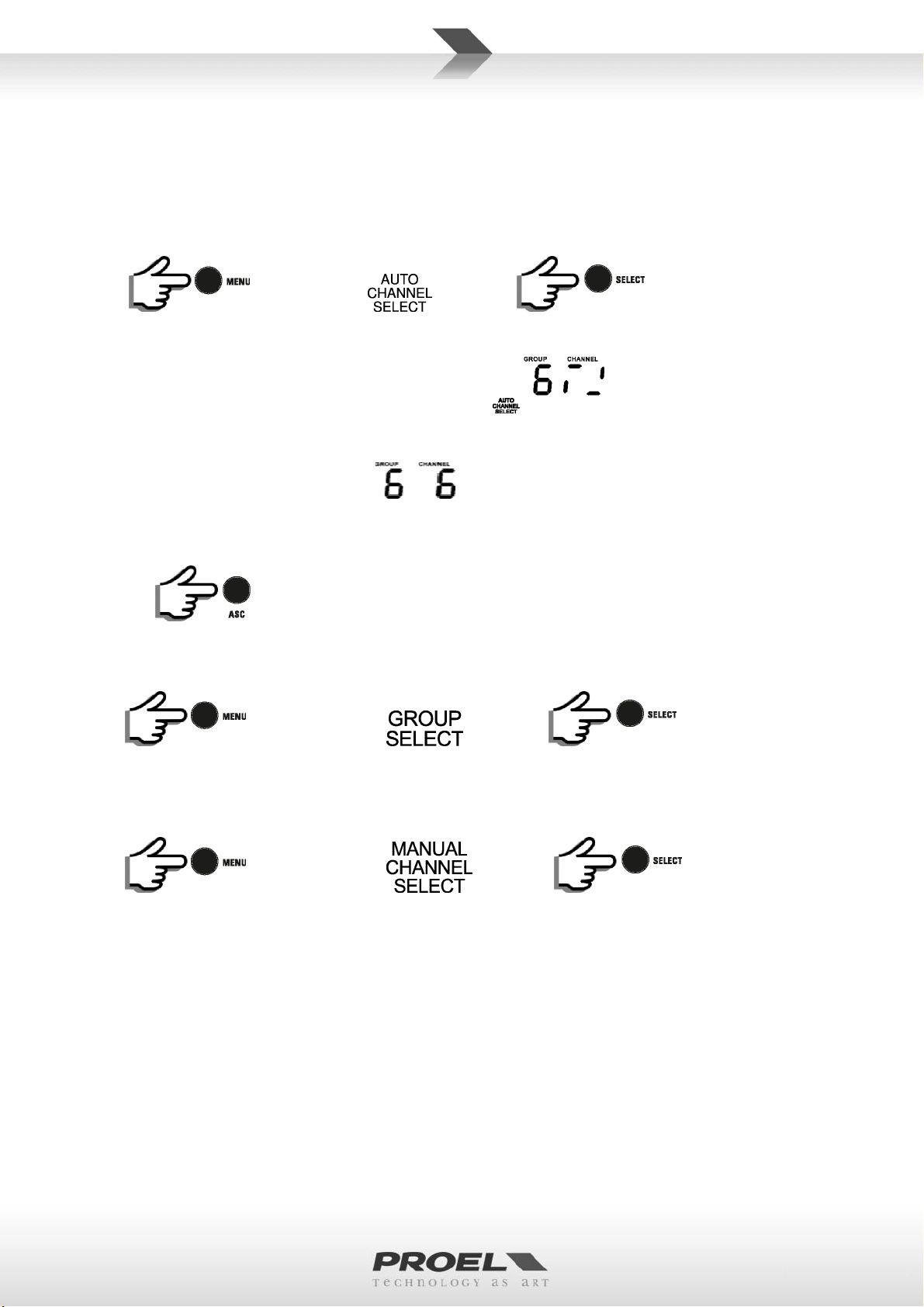
SET AUTOMATICALLY A SINGLE SYSTEM
Be sure that the transmitter is switched OFF.
Press on LCD appears then press , if you don’t press the
button into 5 seconds the receiver goes back to normal operation.
The receiver searches a free channel in the selected group
(note: it searches for a free frequency avoiding previously set channels or TV channels)
and when it is found a fixed channel is set
TURN ON the transmitter and expose its IR to IR of the receiver as show in FIG.11
Press ASC : now the transmitter is programmed to the same channel. In order to be sure check
that you have to see the same channel number on it and that the READY LED on the receiver is ON.
SET MANUALLY A CHANNEL GROUP
Press X 2: on LCD appears , then press to choose the channel
group from 1 to 14.
If you don’t press any button after 5 seconds the transmitter goes back to normal operation.
SET MANUALLY A CHANNEL NUMBER
Press X 3: on LCD appears then press to choose the channel
from 1 to 11.
If you don’t press a button for 5 seconds the transmitter goes back to normal operation.
SET AUTOMATICALLY THE SECOND RECEIVER
After you have set the first receiver and transmitter, leaving ON the first transmitter repeat the operation for
the second receiver and transmitter: the second receiver automatically detects the first transmitter channel,
discards its channel and selects another free channel to set the second transmitter.
SET AUTOMATICALLY THE THIRD AND SUBSEQUENTLY RECEIVERS
Set another group every two receiver-transmitter and, leaving ON the previous transmitters, set the other
receiver-transmitter channels: this method DO NOT AVOID completely THE INTERMODULATION problem but
it reduces its probability.

10
CHECK THE FREQUENCY OF THE GROUP-CHANNEL
Press X 4: on LCD appears , then press and hold,
the correspondent frequency remains on the display until the button is released.
THE GROUP-CHANNEL FREQUENCY TABLES
The TAB.1 shows the channel list and the frequency group in the range 551.000 - 581.000 MHz.
SET MANUALLY THE CHANNELS TO AVOID INTERMODULATION
Starting from the setup of the third radio-mic and so on a problem will occur: INTERMODULATION.
In practice, when three or more transmitters are placed in the same location their transmitting channel
frequencies could be combined together to produce other spurious frequencies. These frequencies can be
revealed from the internal circuitry of the other receivers bring them unusable.
To avoid this problem we have prepared two table (one for each radio range) of compatible frequencies that
avoid the intermodulation problem.
Combining these frequencies of the GROUP-CHANNEL you can choose and set at least 6 channel for each
radio range. The only inconvenient is that to be sure that you are using a right frequency set you have to
program each receiver manually one by one.
ACCESSORIES
The following table shows all the accessories available for the RMW1000 system (for more information visit
the PROEL web site www.proel.com):
Proel code Description
RMADRK1 19” rack adapter for 2 RMW1000 units
RMADRK2 19” rack adapter for single RMW1000 unit
PA UHFSPLITAL Antenna Splitter with booster for 4 RMW1000 units, 1 rack unit
ANT700 4 dB GAIN Yagi directional Antenna for mic stand
HCM10V2 High performance Cardioid Headset Microphone for singers (body colour)
HCM08PRO High performance Omnidirectional Headset Microphone for actors (body colour)
HCM23 Premium Omnidirectional Headset Microphone (body colour)
HCM38 Premium Cardioid Headset Microphone for singers (black colour)
HCS30 High performance Cardioid Miniature Condenser Microphone for Sax and Violin
HCS30+HCSD High performance Cardioid Miniature Condenser Microphone for Classic Guitar
HCS30+HCSA High performance Cardioid Miniature Condenser Microphone for Cello
HCS20 Premium Cardioid Microphone for wind instruments Sax, Clarinet, Trumpet
LCH370 High-quality Cardioid miniature Broadcast Lavalier Microphone
LCH200 Premium Omnidirectional miniature Lavalier Microphone

11
TIPS TO IMPROVE WIRELESS SYSTEM PERFORMANCE
If you encounter interference or dropouts, try the following suggestions:
• Choose a different receiver channel
• Reposition the receiver so there is nothing obstructing a line of sight to the transmitter (including
the audience)
• Avoid placing transmitter and receiver where metal or other dense materials may be present
• Move the receiver to the top of the equipment rack
• Remove nearby sources of wireless interference, such as cell phones, two-way radios, computers,
media players, Wi-Fi devices, and digital signal processors
• Charge or replace the transmitter battery
• Keep transmitters more than two meters apart
• Keep the transmitter and receiver more than 5 meters apart
• During sound check, mark trouble spots and ask presenters or performers to avoid those areas

12
TECHNICAL SPECIFICATION
rms
rms
RMW1000 – UHF PLL 121 Channel Receiver
RF Channels 121 frequency preset
RF Frequency Band UHF: 551-581 MHz
RF Receiver Type PLL UHF Synthesized
RF Modulation type FM (F3E)
RF Sensibility -105 dBm / 12 dB SINAD
RF Image/Spurious Rejection > 70 dB
RF Interference Rejection > 70 dB
RF Frequency Stability ± 0.005% (-10 ÷ +50 °c)
THD Distortion < 0.8%
S/N Ratio > 90 dB
Dynamic Ratio > 105 dB
Frequency Response 50 Hz – 15 KHz (±3 dB)
XLR balanced nominal audio output -10 dBu (245 mV
JACK unbalanced nominal audio output 0 dBu (775 mV
Power Supply 12 V DC 600 mA
Dimensions (WxDxH) 197 x 134 x 42 mm
Weight 0.82 Kg
RMW1M – Handheld Microphone UHF PLL 121 Channels Transmitter
RF Channels 121 frequency preset
RF Frequency Band UHF: 551-581 MHz
RF Power max 10 mW
Modulation method FM (F3E)
RF Max deviation ± 35 KHz compressor-expander system
RF Frequency Stability ± 0.005% (-10 ÷ +50 °c)
Spurious Emission under limits EN 300 422
Frequency Response 50 Hz – 15 KHz (±3 dB)
Microphone type Dynamic Cardioid
Mic sensitivity 0 / -10dB
Power Supply 2x1.5V AA alkaline battery
Dimensions (WxDxH) 64 x 110 x 19 mm
Weight 0.29 Kg
RMW1H – Bodypack UHF PLL 121 Channels Transmitter
RF Channels 121 frequency preset
RF Frequency Band UHF: 551-581 MHz
RF Power max 10 mW
Modulation method FM (F3E)
RF Max deviation ± 35 KHz compressor-expander system
RF Frequency Stability ± 0.005% (-10 ÷ +50 °c)
Spurious Emission under limits EN 300422
Frequency Response 50 Hz – 15 KHz (±3 dB)
Microphone included Headset condenser type Cardioid pattern
Input connector TA3F (mini XLR3 pin)
)
)

13
Connector Pin Assignments Pin 1: Tied to Ground
Pin 2: Tied to +5 V
Pin 3: Tied to Audio
Power Supply 2x1.5V AA alkaline battery
Dimensions (WxDxH) 64 x 110 x 19 mm
Weight 0,1 Kg
TA3F (mini XLR 3 pin)

14
TRATTAMENTO DEL DISPOSITIVO ELETTRICO OD ELETTRONICO A FINE VITA ...................................... 15
AVVERTENZE PER LA SICUREZZA ........................................................................................................... 15
IN CASO DI GUASTO ............................................................................................................................... 15
IMBALLAGGIO, TRASPORTO E RECLAMI ................................................................................................ 15
GARANZIE E RESI .................................................................................................................................... 15
MANUTENZIONE E LIMITAZIONI D’USO ................................................................................................ 16
ALIMENTAZIONE .................................................................................................................................... 16
AVVERTENZE PER L’UTILIZZO E CONFORMITÀ CE ................................................................................. 17
INTRODUZIONE ...................................................................................................................................... 18
DESCRIZIONE ......................................................................................................................................... 18
RICEVITORE RMW1000 .......................................................................................................................... 18
TRASMETTITORE A MANO RMW1M ..................................................................................................... 19
TRASMETTITORE BODYPACK RMW1H ................................................................................................... 20
ISTRUZIONI OPERATIVE ......................................................................................................................... 20
SOSTITUZIONE BATTERIE ....................................................................................................................... 20
COME INDOSSARE IL BODYPACK RMW1H............................................................................................. 20
IMPOSTAZIONE AUTOMATICA DI UN SISTEMA SINGOLO ..................................................................... 21
IMPOSTAZIONE MANUAE DI UN GRUPPO DI CANALI ........................................................................... 21
IMPOSTAZIONE MANUALE DI UN NUMERO DI CANALE ....................................................................... 21
IMPOSTAZIONE AUTOMATICA DEL SECONDO RICEVITORE .................................................................. 21
IMPOSTAZIONE AUTOMATICA DEL TERZO E DEI SUCCESSIVI RICEVITORI ............................................ 21
CONTROLLARE LA FREQUENZA DEL GRUPPO-CANALE ......................................................................... 21
LE TABELLE GRUPPO-CANALE FREQUENZA ........................................................................................... 22
IMPOSTAZIONE MANUALE DEI CANALI PER EVITARE L’INTERMODULAZIONE ..................................... 22
ACCESSORI ............................................................................................................................................. 22
SPECIFICHE TECNICHE ............................................................................................................................ 23
MIGLIORARE LE PRESTAZIONI DEL SISTEMA WIRELESS ........................................................................ 23
TA3F (mini XLR 3 pin) ............................................................................................................................. 24
TAB.1 ...................................................................................................................................................... 25

15
TRATTAMENTO DEL DISPOSITIVO ELETTRICO OD ELETTRONICO A FINE VITA
Il marchio riportato sul prodotto o sulla documentazione indica che il prodotto non deve essere
smaltito con altri rifiuti domestici al termine del ciclo di vita. Per evitare eventuali danni
all’ambiente si invita l’utente a separare questo prodotto da altri tipi di rifiuti e di riciclarlo in
maniera responsabile per favorire il riutilizzo sostenibile delle risorse materiali. Gli utenti
domestici sono invitati a contattare il rivenditore presso il quale è stato acquistato il prodotto o l’ufficio locale
preposto per tutte le informazioni relative alla raccolta differenziata e al riciclaggio per questo tipo di
prodotto. Gli utenti aziendali sono invitati a contattare il proprio fornitore e verificare i termini e le condizioni
del contratto di acquisto. Questo prodotto non deve essere smaltito unitamente ad altri rifiuti commerciali.
AVVERTENZE PER LA SICUREZZA
• ATTENZIONE - Prima di utilizzare il prodotto, si prega di leggere attentamente le seguenti istruzioni per la
sicurezza. Prendere visione del manuale d’uso e conservarlo per successive consultazioni. Durante l’uso
di un prodotto elettrico devono essere sempre prese precauzioni di base onde evitare danni a cose o
persone, incluse le seguenti:
• In presenza di bambini, controllare che il prodotto non rappresenti un pericolo.
• Posizionare l’apparecchio al riparo dagli agenti atmosferici e a distanza di sicurezza dall’acqua, dalla
pioggia e dai luoghi ad alto grado di umidità.
• Collocare o posizionare il prodotto lontano da fonti di calore quali radiatori, griglie di riscaldamento e
ogni altro dispositivo che produca calore.
• Evitare che qualsiasi oggetto o sostanza liquida entri all’interno del prodotto.
• Il prodotto deve essere connesso esclusivamente alla alimentazione elettrica delle caratteristiche
descritte nel manuale d’uso o scritte sul prodotto.
IN CASO DI GUASTO
• In caso di guasto o manutenzione questo prodotto deve essere ispezionato da personale qualificato
quando:
Sostanze liquide sono penetrate all’interno del prodotto.
Il prodotto è caduto e si è danneggiato.
Il prodotto non funziona normalmente esibendo una marcato cambio di prestazioni.
• Non intervenire sul prodotto.
• Rivolgersi a un centro di assistenza autorizzato Proel.
IMBALLAGGIO, TRASPORTO E RECLAMI
• L’imballo è stato sottoposto a test di integrità secondo la procedura ISTA 1A. Si raccomanda di controllare
il prodotto subito dopo l’apertura dell’imballo.
• Se vengono riscontrati danni informare immediatamente il rivenditore. Conservare quindi l’imballo
completo per permetterne l’ispezione.
• Proel declina ogni responsabilità per danni causati dal trasporto.
• Le merci sono vendute “franco nostra sede” e viaggiano sempre a rischio e pericolo del distributore.
• Eventuali avarie e danni dovranno essere contestati al vettore. Ogni reclamo per imballi manomessi
dovrà essere inoltrato entro 8 giorni dal ricevimento della merce.
GARANZIE E RESI
• I Prodotti Proel sono provvisti della garanzia di funzionamento e di conformità alle proprie specifiche,
come dichiarate dal costruttore.
• La garanzia di funzionamento è di 24 mesi dopo la data di acquisto. I difetti rilevati entro il periodo di

16
garanzia sui prodotti venduti, attribuibili a materiali difettosi o difetti di costruzione, devono essere
tempestivamente segnalati al proprio rivenditore o distributore, allegando evidenza scritta della data di
acquisto e descrizione del tipo di difetto riscontrato. Sono esclusi dalla garanzia difetti causati da uso
improprio o manomissione. Proel SpA constata tramite verifica sui resi la difettosità dichiarata, correlata
all’appropriato utilizzo, e l’effettiva validità della garanzia; provvede quindi alla sostituzione o riparazione
dei prodotti, declinando tuttavia ogni obbligo di risarcimento per danni diretti o indiretti eventualmente
derivanti dalla difettosità.
MANUTENZIONE E LIMITAZIONI D’USO
• Pulire il prodotto unicamente con un panno asciutto.
• I Prodotti Proel sono destinati esclusivamente ad un utilizzo specifico di tipo sonoro: segnali di ingresso di
tipo audio (20Hz-20kHz). Proel declina ogni responsabilità per danni a terzi causati da mancata
manutenzione, manomissioni, uso improprio o installazione non eseguita secondo le norme di sicurezza.
• Proel S.p.A. si riserva di modificare il prodotto e le sue specifiche senza preavviso.
• Proel S.p.A. declina ogni responsabilità per danni a terzi causati da mancata manutenzione,
manomissioni, uso improprio o installazione non eseguita secondo le norme di sicurezza e a regola
d'arte.
ALIMENTAZIONE
• Il prodotto deve essere connesso esclusivamente alla alimentazione elettrica delle caratteristiche
descritte nel manuale d’uso o scritte sul prodotto.
• Se la spina in dotazione non combacia con la presa, rivolgersi ad un elettricista per far installare una
presa appropriata.
• Quando si scollega l’apparato alla rete tenere saldamente sia la spina che la presa.
• Quando l’unità non viene utilizzata per un periodo prolungato, interrompere l’alimentazione estraendo la
spina dalla presa dell’alimentazione.
• Per evitare danni alla linea d’alimentazione dell’apparato, non mettere in trazione il cavo d’alimentazione
e non utilizzare un cavo attorcigliato.
• Per evitare il danneggiamento del cavo d’alimentazione dell’apparato, assicurarsi che questo non venga
calpestato o schiacciato da oggetti pesanti.

17
AVVERTENZE PER L’UTILIZZO E CONFORMITÀ CE
TABELLA FREQUENZE AUTORIZZATE PER IL RADIO MICROFONO RMW1000 IN EUROPA AGGIORNATA CON
FREQUENZE DI TRASMISSIONE RMW
1M / RMW1H
551
.000
- 581
.000
AL AT BA
BE BG CH CY DK EE GB HU IS IE LI
CZ FI FR DE GR IT LT MT NO PL SI UA
Licenza individuale richiesta e Implementazione Limitata
RU Licenza individuale richiesta e Implementazione Limitata
ES NON IMPLEMENTATO
GE NON IMPLEMENTATO
IN QUALSIASI NAZIONE L’USO DEI RADIOMICROFONI È SUBORDINATO AD EVENTUALI RADIOTRASMISSIONI
RIFERIRSI SEMPRE ALLE AUTORITA NAZIONALI DELLE FREQUENZE DEL PROPRIO PAESE PER INFORMAZIONI
• Eventuali modifiche di qualsiasi tipo non espressamente autorizzate dalla PROEL S.p.A. possono annullare
il permesso di utilizzo di questo apparecchio.
INFORMATIVA SULLA LICENZA:
• RMW1000 opera nella bande di frequenze: 551 – 581 MHz.
• Una licenza ministeriale è richiesta per l’uso di questo apparecchio. In alcuni paesi potrebbe essere inteso
per uso professionale ed essere soggetto all’ottenimento di una autorizzazione che dipende dal paese in
cui lo si usa. Proel suggerisce all’utilizzatore di contattare l’appropriata autorità alle telecomunicazioni a
proposito della licenza appropriata.
• Questo apparecchio potrebbe essere in grado di funzionare a frequenze non autorizzate nella nazione
e/o regione in cui si trova l’utente, contattare la autorità nazionale alle telecomunicazioni a riguardo delle
frequenze autorizzate per l’uso dei radiomicrofoni nella propria regione.
• Chi usa radiomicrofoni ha la responsabilità di procurarsi la licenza adatta al suo impiego; la concessione di
tale licenza dipende dalla classificazione dell’operatore, dall’applicazione e dalla frequenza selezionata.
• I Prodotti Proel sono conformi alla direttiva LVD 2006 / 95 / EC, secondo lo standard EN 60065 ed EN
50371.
• Il radio-microfonico Proel è conforme ai requisiti essenziali ed alle altre disposizioni pertinenti stabilite
dalla direttiva 2014 / 53 / UE secondo gli standard EN 300422-1; EN 300422-2; EN 301489-01; EN
300489-09.
• La dichiarazione di conformità completa e dettagliata può essere consultata sul sito:
ERC-REC 70-03E DEL 10 OTTOBRE 2012
CODICE NAZIONE
LU LV ME MK MD NL PT RS RO SE SK TR HR
TELEVISIVE
SULLE DISPOSIZIONI DELLE FREQUENZE AUTORIZZATE E PER IL LORO USO A NORMA DI LEGGE
Licenza individuale richiesta
www.proel.com

18
INTRODUZIONE
Grazie per aver scelto un prodotto PROEL e della fiducia riposta nel nostro marchio, sinonimo di
professionalità, accuratezza, elevata qualità ed affidabilità. Tutti i nostri prodotti sono conformi alle
normative CE per utilizzazione continua in impianti di diffusione sonora.
DESCRIZIONE
I radiomicrofoni serie RMW1000 sono sistemi UHF con frequenza controllata da PLL e doppia antenna
diversity, caratterizzati da una trasmissione affidabile e di ottima qualità e dotati di scansione automatica dei
canali e sincronizzazione mediante infrarosso.
Il sistema radio microfonico RMW1000 è composto da 3 parti: ricevitore RMW1000, trasmettitore a mano
RMW1M e trasmettitore tascabile RMW1H. Il sistema è disponibile in 2 diverse configurazioni, ognuna dotata
di una valigetta in ABS per il trasporto:
RMW1000M : RMW1000 + RMW1M
RMW1000H : RMW1000 + RMW1H + microfono headset
Sono disponibili 121 canali/frequenze, che permettono l’uso simultaneo fino a 6 apparati radio senza che
questi interferiscano fra di loro, vedi la spiegazione dettagliata più avanti nel manuale.
RICEVITORE RMW1000
Vedi FIG. 1 a pagina 15:
1. ANTENNA 1
Questa è l’antenna di ricezione 1. Avvitarla e alzarla in posizione verticale durante l’uso. Per una migliore
ricezione posizionare il ricevitore lontano da altri oggetti metallici e a non più di 50m dal trasmettitore.
2. ANTENNA 2
Questa è la seconda antenna di ricezione. Avvitarla e alzarla in posizione verticale durante l’uso. Il circuito
di ricezione interno “diversity” sceglie il miglior segnale da una delle due antenne.
3. DC IN
Connettore per il collegamento dell’adattatore AC/DC: usare esclusivamente l’adattatore fornito nella
confezione.
4. OUTPUT (BALANCED)
Uscita bilanciata livello microfono: collegare mediante un cavo XLR all’ingresso del mixer. Questa è l’uscita
preferita per i collegamenti lunghi.
5. OUTPUT (UNBALANCED)
Uscita sbilanciata livello linea: collegare mediante un cavo jack mono 6.3mm all’ingresso del mixer.
6. VOLUME
Potenziometro Volume: usando un piccolo cacciavite impostare questo controllo ad un livello appropriato
che non saturi il canale di ingresso del mixer.
7. POWER
Interruttore On/off: premere e tener premuto per 2 secondi per accendere/spegnere il ricevitore.
8. READY
LED VERDE: se acceso significa che il trasmettitore sta inviando un segnale radio al ricevitore, se il LED è
spento, controllare se il trasmettitore è spento, o impostato in un’altro canale.
9. AUDIO BAR LED
Visualizza la presenza di un segnale audio: notare che l’indicazione del livello è indipendente
dall’impostazione del VOLUME.
10. LCD DISPLAY
Il display LCD mostra varie informazioni:
L’antenna A sta ricevendo il segnale radio.

19
L’antenna B sta ricevendo il segnale radio.
Il ricevitore è bloccato e i tasti non hanno nessun effetto: premere “menu” e “select” insieme per
bloccare o sbloccare il ricevitore. Bloccando il ricevitore e il trasmettitore si prevengono accidentali
cambiamenti d’impostazione.
Tipicamente il display LCD mostra il canale attualmente in uso (vedi più avanti in questo
manuale per le istruzioni dettagliate sulle impostazioni del canale e la visualizzazione della frequenza).
11. MENU BUTTON
Premendo questo tasto si possono scorrere le opzioni del menu:
Dopo la pressione si hanno 5 secondi per premere il tasto “SELECT” per sceglierne un’opzione, dopodiché
se nessun tasto è stato premuto il ricevitore torna alle operazioni normali (vedi spiegazione dettagliata
più avanti nel manuale).
12. SELECT
Premendo questo tasto si può attivare o cambiare un valore della corrispondente opzione di menu. Dopo
la pressione si hanno 5 secondi per premere nuovamente il tasto “SELECT” per scegliere la successiva,
dopodiché se nessun tasto è stato premuto il ricevitore torna alle operazioni normali (vedi la spiegazione
dettagliata più avanti nel manuale).
13. ASC
Premendo questo tasto il ricevitore invia l’impostazione del canale al trasmettitore microfono o bodypack
mediante la porta IR.
14. IR
Questa è la porta a infrarossi per inviare le impostazioni del canale.
TRASMETTITORE A MANO RMW1M
Vedi FIG. 2 e FIG.5 a pagina 16:
15. GRIGLIA MICROFONO
La griglia protegge la capsula microfonica e incorpora un filtro anti-pop. La capsula microfonica è di tipo
dinamico con figura a cardioide unidirezionale.
16. LCD DISPLAY
Il display LCD display mostra varie informazioni:
le batterie sono completamente cariche e si hanno 6-8 ore di attività usando batterie alcaline.
le batterie sono per metà cariche e si hanno 2-6 ore di attività usando batterie alcaline.
le batterie sono quasi scariche e si hanno 0-2 ore di attività usando batterie alcaline: si suggerisce di
cambiare le batterie al più presto.
Tipicamente il display LCD mostra il canale attualmente in uso (vedi più avanti nel manuale
per le istruzioni dettagliate sulle impostazioni del canale).
17. STATUS LED
Questo LED mostra lo stato del trasmettitore:
OFF: il trasmettitore è acceso ma in mute ( silenziato ) oppure spento.
VERDE: il trasmettitore è acceso e operativo.

20
18. IR
Rimuovendo il coperchio batterie appare la porta a infrarosso per ricevere le impostazioni del canale.
19. VANO BATTERIE
Ruotare il coperchio per accedere al vano batterie ed accedere alla porta a infrarosso.
20. ON –OFF- MUTE
Tenendo premuto questo tasto il trasmettitore si accende , premendo ancora il tasto si può chiudere
(MUTE ) o aprire (UNMUTE - LED GREEN) il microfono. Tenendo premuto il tasto per 3 secondi si può
spegnere il trasmettitore .
TRASMETTITORE BODYPACK RMW1H
Vedi FIG. 8 a pagina 16:
21. ANTENNA
Questa è l’ antenna integrata: non forzarla, non cercare di scollegarla o sostituirla con un’ altra.
22. COPERCHIO VANO BATTERIE
Facendo scorrere la parte bassa del Bodypack si accede al vano batterie e alla porta IR.
23. AUDIO INPUT
T3AF mini XLR presa per ingresso audio per connettere il microfono in dotazione o un’altro tipo.
24. ON o MUTE BUTTON
Premere questo tasto per chiudere (MUTE - LED ORANGE) o aprire (UNMUTE - LED GREEN) il microfono.
Premerlo per 3 secondi per accendere e spegnere il trasmettitore.
25. STATUS LED
Questo LED mostra lo stato del trasmettitore:
OFF: il trasmettitore è spento .
VERDE: il trasmettitore è acceso e operativo.
ARANCIO: il trasmettitore è acceso ma in mute (silenziato).
Premere il tasto per 3 secondi per spegnere il trasmettitore.
26. IR
Rimuovendo il coperchio batterie appare la porta a infrarosso per ricevere le impostazioni del canale
27. REGOLAZIONE GUADAGNO
Switch per impostare il guadagno del microfono Headset, impostarlo a 0dB per il parlato e a -10dB per il
cantato.
ISTRUZIONI OPERATIVE
SOSTITUZIONE BATTERIE
Per la sostituzione delle batterie usare sempre 2x 1.5V tipo AA al LITHIUM o ALKALINE per ottenere I migliori
risultati. Si possono anche usare batterie ricaricabili ma in questo caso il tempo di operatività è inferiore.
Batterie ALKALINE di buona qualità garantiscono un tempo operativo di circa 8 ore.
Per sostituire le batterie sul microfono a mano RMW1M seguire le istruzioni di FIG.3 e 4, rispettando sempre
la polarità segnata all’interno del vano batterie.
Per sostituire le batterie sul trasmettitore bodypack RMW1H seguire le istruzioni di FIG.8 e 9, rispettando
sempre la polarità segnata all’interno del vano batterie.
Ricordarsi sempre di rimuovere le batterie se non si usa il microfono per un lungo periodo di tempo: questo
eviterà la corrosione dei contatti della batteria.
COME INDOSSARE IL BODYPACK RMW1H
Come visibile in FIG.10 è possibile indossare il bodypack a una cintura, cinghia o vestito verticalmente o
orizzontalmente e semplicemente girando la molla dall’altro lato, in ogni caso fare attenzione a non piegare o
tirare l’antenna.

21
IMPOSTAZIONE AUTOMATICA DI UN SISTEMA SINGOLO
Assicurarsi che il trasmettitore sia spento.
Premere su display LCD apparirà quindi premere : se non si
preme il tasto entro 5 secondi il ricevitore ritorna allo stato operativo normale.
Il ricevitore cercherà un canale libero nel gruppo selezionato
(nota: esso cercherà una frequenza libera scartando i canali precedenti o I canali TV)
quando la trova imposta il canale
ACCENDERE il trasmettitore ed esporre il sensore IR al sensore IR del ricevitore, vedi FIG.11.
Premere ASC e il trasmettitore sarà programmato sullo stesso canale: assicurarsi che appaia lo
stesso numero di canale sul display del trasmettitore e che il LED READY sul ricevitore si accenda.
IMPOSTAZIONE MANUAE DI UN GRUPPO DI CANALI
Premere X 2 sul display LCD apparirà quindi premere per
scegliere il gruppo di canali tra 1 e 14.
Se non si preme un tasto entro 5 secondi il trasmettitore ritorna allo stato operativo normale.
IMPOSTAZIONE MANUALE DI UN NUMERO DI CANALE
Premere X 3 sul display LCD apparirà quindi premere per
scegliere il canale da 1 a 16.
Se non si preme un tasto entro 5 secondi il trasmettitore ritorna allo stato operativo normale.
IMPOSTAZIONE AUTOMATICA DEL SECONDO RICEVITORE
Dopo aver impostato il primo ricevitore e trasmettitore, lasciando ACCESO il primo trasmettitore ripetere
l’operazione di impostazione automatica per il secondo ricevitore e trasmettitore: il secondo ricevitore rileva
automaticamente il canale del primo trasmettitore, scarta questo canale e sceglie un altro canale libero per
impostare il secondo trasmettitore.
IMPOSTAZIONE AUTOMATICA DEL TERZO E DEI SUCCESSIVI RICEVITORI
Impostare un’altro gruppo ogni due ricevitori-trasmettitori e, lasciando ACCESI i precedenti trasmettitori,
impostare i successivi canali ricevitore-trasmettitore: questo metodo NON EVITA IL PROBLEMA DELLA
INTERMODULAZIONE completamente ma ne riduce la probabilità.
CONTROLLARE LA FREQUENZA DEL GRUPPO-CANALE
Premere X 4 sul display LCD apparirà quindi premere e tenere premuto

22
la frequenza corrispondente rimane visibile fino a quando il tasto sarà rilasciato.
TABELLA GRUPPO-CANALE FREQUENZA
La TAB.1 mostra la lista di canali e delle frequenze di ciascun gruppo nella gamma del modello 551.000 -
581.000 MHz.
IMPOSTAZIONE MANUALE DEI CANALI PER EVITARE L’INTERMODULAZIONE
A partire dalla impostazione del terzo sistema e successivi si verifica un problema: L’INTERMODULAZIONE.
In pratica quando tre o più trasmettitori sono collocati nel medesimo spazio le loro frequenze di trasmissione
di canale potrebbero combinarsi assieme in modo da produrre altre frequenze spurie: queste frequenze
possono essere rilevate dai circuiti interni degli altri ricevitori rendendoli inutilizzabili.
Per evitare questo problema, è stato inserito in questo manuale una tabella di frequenze compatibili adatte
ad evitare il problema dell’intermodulazione.
Combinando queste frequenze dei GROUP-CHANNEL, si possono scegliere almeno 6 canali per ogni gamma
di frequenze: per essere certi di usare l’esatta frequenza è necessario, però, impostare ogni ricevitore
manualmente.
ACCESSORI
La seguente tabella mostra tutti gli accessori disponibili per il sistema RMW1000 (per maggiori informazioni
visitate il sito web PROEL www.proel.com).
Codice PROEL Descrizione
RMADRK1 Adattatore a rack 19” per 2 unità RMW1000
RMADRK2 Adattatore a rack 19” per una singola unità RMW1000
PA UHFSPLITAL Antenna Splitter con preamplificatore per 4 unità RMW1000, da 1 unità rack
ANT700 Antenna direzionale Yagi da 4 dB di guadagno per asta microfono
HCM10V2 Microfono Headset Cardioide alte prestazioni ideale per cantanti (colore beige)
HCM08PRO Microfono Headset Omni alte prestazioni ideale per attori (colore beige)
HCM23 Microfono Headset Omni Premium (colore beige)
HCM38 Microfono Headset Cardioide Premium per cantanti (colore nero)
HCS30 Microfono a condensatore Cardioide alte prestazioni per Sax e Violino
HCS30+HCSD Microfono a condensatore Cardioide alte prestazioni per Chitarra Classica
HCS30+HCSA Microfono a condensatore Cardioide alte prestazioni per Violoncello
HCS20 Microfono a condensatore Cardioide Premium per strumenti a fiato
LCH370 Microfono a condensatore Cardioide alte prestazioni tipo Lavalier
LCH200 Microfono a condensatore Omni Premium tipo Lavalier

23
MIGLIORARE LE PRESTAZIONI DEL SISTEMA WIRELESS
rms
rms
In presenza di interferenze o perdite di segnale, provate a seguire le seguenti indicazioni:
• Impostare un diverso canale nel ricevitore
• Posizionate il ricevitore in modo che non vi siano ostacoli (pubblico incluso) sulla linea ottica verso il
trasmettitore
• Non collocate né il trasmettitore né il ricevitore in prossimità di oggetti metallici, scaffalature ,impalcature
• Collocate il ricevitore nella parte superiore del rack per apparecchi
• Rimuovete ogni sorgente di interferenza tra i dispositivi radiomicrofonici, quali telefoni cellulari, walkie-
talkie, computer, riproduttori digitali, dispositivi Wi-Fi e processori di segnali digitali
• Controllate lo stato di carica delle batterie del trasmettitore
• Tenete i trasmettitori ad una distanza di oltre due metri uno dall'altro
• Tenete trasmettitore e ricevitore ad una distanza di oltre 5 metri uno dall'altro
• Prima di ogni spettacolo, contrassegnate le zone problematiche e chiedete a presentatori o esecutori di
evitarle
SPECIFICHE TECNICHE
RMW1000 – Ricevitore 121 Canali UHF PLL
Canali RF 121 frequenze preimpostate
Gamma di frequenze RF UHF: 551-581 MHz
Tipo di ricezione RF UHF con sintonizzatore PLL
Tipo di modulazione RF FM (F3E)
Sensibilità RF -105 dBm / 12 dB SINAD
Reiezione immagine RF > 70 dB
Reiezione interferenza RF > 70 dB
Stabilità frequenza RF ± 0.005% (-10 ÷ +50 °c)
Distorsione THD < 0.8%
Rapporto S/N > 90 dB
Rapporto Dinamico > 105 dB
Risposta in frequenza 50 Hz – 15 KHz (±3 dB)
Livello nominale uscita XLR bilanciata -10 dBu (245 mV
Livello nominale uscita JACK sbilanciata 0 dBu (775 mV
Alimentazione 12 V DC 600 mA
Dimensioni (LxPxA) 197 x 134 x 42 mm
Peso 0.82 Kg
RMW1M – Trasmettitore Microfono a mano 121 Canali UHF PLL
Canali RF 121 frequenze preimpostate
Gamma di frequenze RF UHF: 551-581 MHz
Potenza RF max 10 mW
Tipo di modulazione RF FM (F3E)
Max deviazione RF ± 35 KHz con sistema compressore-espansore
Stabilità frequenza RF ± 0.005% (-10 ÷ +50 °c)
Emissioni Spurie RF Sotto i limiti imposti dalla EN 300 422
Risposta in frequenza 50 Hz – 15 KHz (±3 dB)
)
)

24
Tipo di microfono Dinamico Cardioide
Sensibilità Microfono 0 / -10dB
Alimentazione 2x1.5V AA batterie alcaline
Dimensioni (DxA) 52 x 245 mm
Peso 0.29 Kg
RMW1H – Trasmettitore Bodypack 121 Canali UHF PLL
Canali RF 121 frequenze preimpostate
Gamma di frequenze RF UHF: 551-581 MHz
Potenza RF max 10 mW
Tipo di modulazione RF FM (F3E)
Max deviazione RF ± 35 KHz con sistema compressore-espansore
Stabilità frequenza RF ± 0.005% (-10 ÷ +50 °c)
Emissioni Spurie RF Sotto i limiti imposti dalla EN 300422
Risposta in frequenza 50 Hz – 15 KHz (±3 dB)
Microfono incluso Headset Cardioide a condensatore
Connettore di Ingresso TA3F (mini XLR 3 pin)
Assegnazione Pin ingresso Pin 1: Massa
Pin 2: +5 V
Pin 3: Audio in
Alimentazione 2x1.5V AA batterie alcaline
Dimensioni (LxPxA) 64 x 110 x 19 mm
Peso 0,1 Kg
TA3F (mini XLR 3 pin)

25
TAB.1
GROUP 1 2 3 4 5 6 7
CHANNEL
1 557.250 557.225 556.950 556.525 557.450 556.600 556.650
2 560.825 560.800 558.950 557.925 559.025 558.050 559.125
3 562.975 562.950 560.325 559.650 561.800 560.275 560.450
4 564.800 564.775 562.425 560.850 562.950 561.750 562.150
5 566.325 566.300 564.050 563.400 565.125 562.850 563.250
6 567.550 567.525 565.275 564.525 566.575 564.550 564.725
7 569.175 569.150 566.800 566.275 567.725 565.875 566.950
8 571.275 571.250 568.625 567.550 569.800 568.350 568.400
9 572.650 572.625 570.775 569.775 569.450 569.500
10 574.650 574.625 574.350
11 575.750 575.800 575.775
GROUP 8 9 10 11 12 13 14
CHANNEL
1
2
3
4
5
6
7
8
9
10 568.575 579.550
11 569.975 580.975
551.000 562.025 557.400 556.900 557.200 559.850 562.150
553.000 563.425 564.300 558.100 559.800 563.000 567.670
554.375 564.525 572.400 562.200 561.900 565.700 570.400
556.475 566.400 565.300 563.000 567.050 572.500
562.000 567.500 570.100 565.200 569.900 573.450
563.100 568.900 572.100 567.700 572.500 575.300
564.500 570.000 573.200 573.600
565.600 573.825 575.600 575.500
567.475 575.975

26

27

28

29

30
PROEL S.p.A.
(World Headquarters - Factory)
Via alla Ruenia 37/43
64027 Sant’Omero (Te) – Italy
Tel: +39 0861 81241
Fax: +39 0861 887862
www.proel.com
 Loading...