

THEATRE PROJECTOR 1000W
PLFT100PCN – PLFT100FCN

INDICE
INDICE
INDICEINDICE
AVVERTENZA PER LA SICUREZZA DELL’APPARECCHIO...................2
INSTALLAZIONE PROIETTORE....................................................................3
MONTAGGIO LAMPADA...............................................................................3
ALIMENTAZIONE A RETE..............................................................................3
REGOLAZIONE FASCIO..................................................................................4
PORTAGELATINA.............................................................................................4
MANUTENZIONE .............................................................................................4
Tutte le specifiche riportate nel presente manuale sono soggette a variazioni senza
preavviso
Rev. 00 – 49/2007

NEL CONTINUO SFORZO DI MIGLIORARE LA QUALITÀ DEI SUOI PRODOTTI, LA
PROEL SPA PUÒ INTRODURRE CAMBIAMENTI TECNICI NEL CORSO DELLA
PRODUZIONE. PERTANTO LE SPECIFICHE TECNICHE ED IL DISEGNO POSSONO
SUBIRE VARIAZIONI SENZA PREAVVISO. LA PROEL SPA NON È RESPONSABILE DEI
DANNI DERIVANTI DA USO IMPROPRIO O DIVERSO DA QUELLO PREVISTO.
ATTENZIONE !
ATTENZIONE ! LA SICUREZZA DELL’APPARECCHIO È GARANTITA SOLO CON L’USO
ATTENZIONE !ATTENZIONE !
APPROPRIATO DELLE SEGUENTI ISTRUZIONI, PERTANTO È NECESSARIO
CONSERVARLE ACCURATAMENTE
ATTENZIONE !
ATTENZIONE ! PRIMA DI EFFETTUARE QUALSIASI TIPO DI INTERVENTO È
ATTENZIONE !ATTENZIONE !
.
NECESSARIO TOGLIERE TENSIONE.
AVVERTENZA PER LA SICUREZZA DELL’APPARECCHIO
- Non smontare e non apportare modifiche all’apparecchio.
- Evitare che nell’apparecchio penetrino liquidi infiammabili, acqua o oggetti
metallici (IP20).
- Non installare l’apparecchio in luoghi soggetti ad eccessiva umidità.
- Apparecchio non idoneo al montaggio diretto su superfici normalmente
infiammabili.
- Mantenere una distanza di almeno 0,5 m tra il proiettore e le superfici adiacenti
infiammabili.
- L’apparecchio di illuminazione deve essere usato solo se completo del suo
schermo di protezione.
- Gli schermi di protezione, le lenti o i filtri per l’ultr avioletto devono esser e sostituiti
se sono visibilmente danneggiati al punto che la loro efficacia ne sia diminuita,
per esempio da fessure o incisioni profonde.
- La lampada deve essere sostituita se essa è stata danneggiata o deformata dal
calore.
- Mantenere tra la lampada e la superficie illuminata una distanza minima di
almeno 2,5 m.
- Non esporsi direttamente ai raggi della lampada in quanto dannosi agli occhi.
- La lampada raggiunge temperature molto elevate: prima di maneggiarla
assicurarsi che si sia raffreddata (attendere almeno 10 minuti dopo lo
spegnimento della lampada per aprire il vano lampada).
- È consigliato mantenere una buona pulizia delle lenti per mantenere una invariata
resa luminosa nel tempo.
2
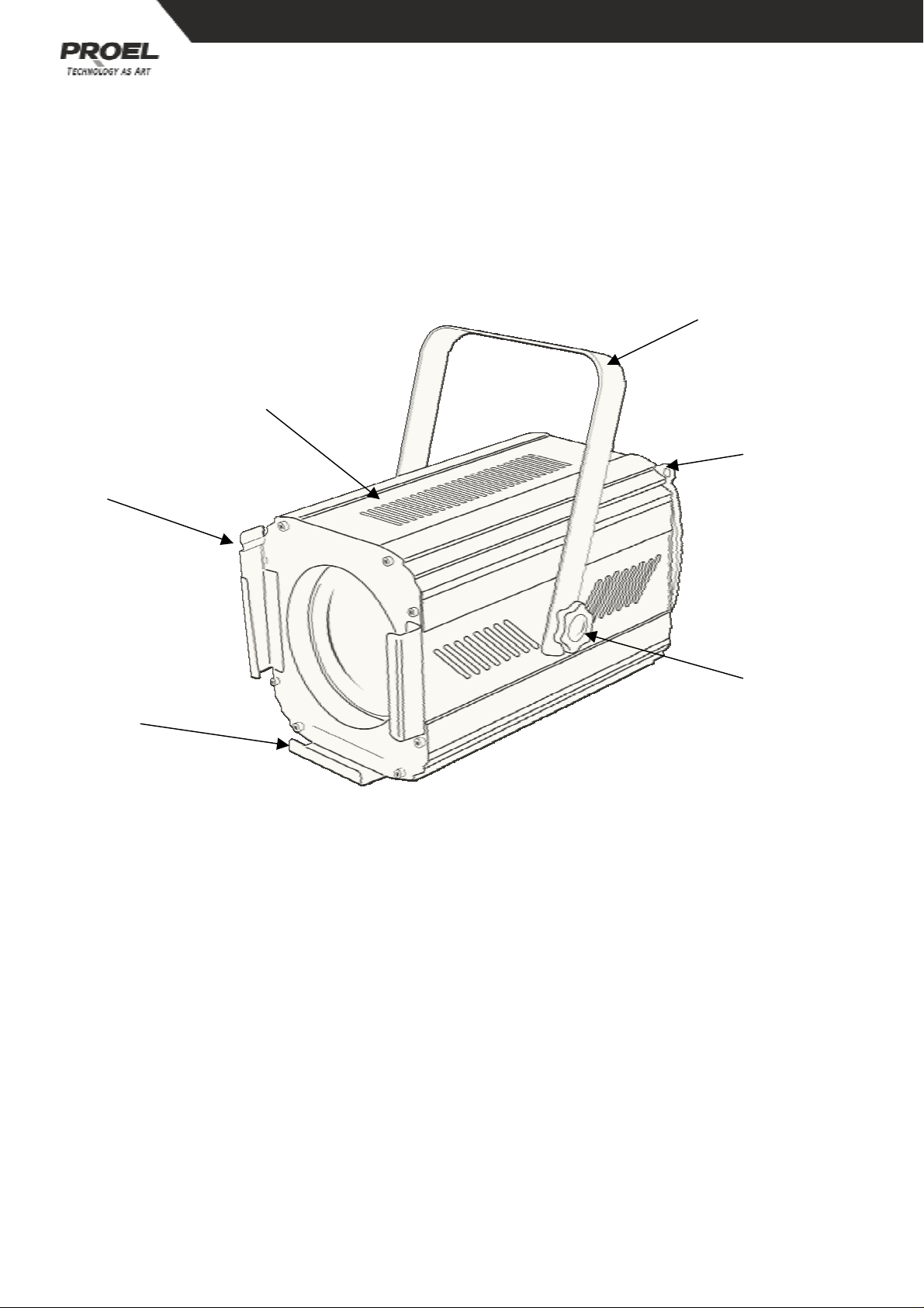
INSTALLAZIONE PROIETTORE
Fissare il proiettore per mezzo dell’apposito foro diametro 11 mm posto sulla
forcella (1). Si deve agganciare il proiettor e tramite la catena di sicurezza fissando la
nell’apposito foro (2). Mediante il pomolo (3) si può regolare l’inclinazione del
proiettore (+ 90°/- 45°). È possibile ruotare la forcella anche verso la parte inferiore
del proiettore.
1
6
2
5
3
4
MONTAGGIO LAMPADA
Aprire lo sportello superiore (6) svitando la vite posto nella parte posteriore del
proiettore. Inserire la lampada T19 1000W nell’apposito portalampada. (Utilizzare
lampade adeguate alla tensione di rete 120V/ 220V/ 240V). Manegg iare la lampada
con cura senza forzare eccessivamente utilizzando un panno per evitare il contatto
diretto del bulbo con le dita. Richiudere lo sportello e riavvitare l’apposita vite.
Cod. lampada PLLP1000T19.
ALIMENTAZIONE A RETE
Alimentare il proiettore mediante la presa in dotazione collegando il filo blu al
neutro (N) della presa, il filo marrone alla fase (L) ed il f ilo giallo - verde al polo di
terra. È obbligatorio che il collegamento di terra ve nga eseguito secondo le norme
in vigore.
3

REGOLAZIONE FASCIO
Tramite il pomolo posto sulla parte bassa del lato posteriore del proiettore, si
regolano le dimensione del fascio luminoso. Girando in senso orario il fascio si
stringe, in senso antiorario il fascio si allarga.
PORTAGELATINA
Nella parte anteriore del proiettore si trova il porta- ge latina (4). Tirare la molla (5) e
sfilare il porta- gelatina. Inserire la gelatina e rimontare il tutto. (Si raccomanda di
utilizzare gelatina ad alta resistenza termica).
MANUTENZIONE
In caso di danneggiamento o rottura delle lenti del proiettore, procedere alla
sostituzione. Sostituire la lampada se danneggiata o nel caso abbia subito delle
deformazioni a causa del calore.
Per avere un buon funzionamento del proiettore è consigliabile effettuare una
pulizia periodica (sei mesi) delle lenti per mantenere una invariata resa luminosa
delle lenti nel tempo. Si raccomanda di non usare nessun tipo di solvente per la
pulizia delle parti in vetro.
4

CONTENTS
CONTENTS
CONTENTSCONTENTS
SAFE USAGE OF THE PROJECTOR.............................................................6
INSTALLING THE PROJECTOR.....................................................................7
FITTING THE LAMP..........................................................................................7
POWER SUPPLY................................................................................................7
BEAM ADJUSTMENT.......................................................................................8
FILTER FRAME...................................................................................................8
MAINTENANCE.................................................................................................8
The specifications related in this manual are subject to modifications without any
advance notice
Rev. 00 – 49/2007

PLEASE NOTE THAT AS PART OF PROEL SPA’S ONGOING COMMITMENT TO
CONTINUOUS PRODUCT DEVELOPMENT, SPECIFICATION ARE SUBJECT TO CHANGE
WITHOUT NOTICE. WHILST EVERY CARE IS TAKEN IN THE PREPARATION OF THIS
MANUAL PROEL SPA RESERVES THE RIGHT TO CHANGE SPECIFICATIONS IN THE
COURSE OF THE PRODUCT IMPROVEMENT. THE PUBLISHERS CANNOT BE HELD
RESPONSIBLE FOR THE ACCURACY OF THE INFORMATION HEREIN, OR ANY
CONSEQUENCE ARISING FROM THEM.
ATTENTION !
ATTENTION ! THIS INSTRUCTION MANUAL CONTAINS IMPORTANT INFORMATION
ATTENTION !ATTENTION !
ABOUT THE INSTALLATION AND USE OF THE PROJECTOR. PLEASE READ AND
FOLLOW THESE INSTRUCTION CAREFULLY.
ATTENTION !
ATTENTION ! ALWAYS ENSURE THAT THE POWER TO THE PROJECTOR IS
ATTENTION ! ATTENTION !
DISCONNECTED BEFORE OPENING THE PROJECTOR COMMENCING ANY
MAINTENANCE WORK.
SAFE USAGE OF THE PROJECTOR
- Do not attempt to dismantle and modify the projector.
- Do not allow contact with water or any other fluids, or metallic objects (IP20).
- Do not install the projector in areas of high humidity.
- The projector is not designed or intended to be mounted directly on the
inflammable surface
- Keep at least 0.5 m distance between the projector and adjacent inflammable
surfaces.
- The projector must only be used complete with its protective grill and/ or front
lens.
- The protective grill, lenses or ultraviolet filter m ust be changed if they are visibly
damaged to the point at which their effectiveness is diminished, for example by
becoming cracked or deeply scratched.
- The lamp must be changed if it becomes damaged or deformed by heat.
- Keep at least 2.5 m between the lamp and the illuminated surfaces.
- Avoid direct exposure to the light from the lamp. The light is armful to the eye.
- The lamp reaches very high temperatures, allow at least 10 minutes for the lamp
to cool completely before attempting to handle it. Ensure the lamp is cool before
attempting to handle it.
- To ensure the reliability of the projector it should be kept clean. The lens and
dichroic filters should also be regularly cleaned to maintain an optimum light
output.
- In locations such as discotheques the objective lens should be cleaned every week
as smoke fluid can condense on it and very quickly reduce the light output.
6

INSTALLING THE PROJECTOR
The projector should be mounted with an M10 bolt through the 11 mm hole in its
bracket (1). For safety the projector should have a secondary fixing with a safety
chain through the fixing eye (2). The projector bracket allows an angle adjustment
of (+ 90°/- 45°) and, once positioned, the knob (3) should be firmly tightened. The
projector mounting bracket can also be easily rotated to be positioned on the
underside of the projector for tripod mounting etc.
1
6
2
5
3
4
FITTING THE LAMP
The lamp access hatch (4) is released by remove the rear screw, located on the rear
of the projector. Insert the T19 1000W lamp into its socket. (Use only the lamp
version that is correct for the mains voltage 120V / 220V / 240V). Insert the lamp
with care and without using excessive force. Use a cloth to hold the lamp and do
not touch the glass of the lamp directly with your hands. Close the access hatch.
Lamp code PLLP1000T19.
POWER SUPPLY
Use the plug provided to connect the mains power to the projector. The blue wire
is neutral (N), the brown wire is live (L), and the yellow and green wire is earth (E).
IMPORTANT: it is essential that each projector is correctly earthed and that
electrical installation conforms to all relevant standards.
7

BEAM ADJUSTMENT
To adjust the beam width turn clockwise and anticlockwise the rear knob on the
rear side of the projector, taking care not to damage the lamp.
Maximum beam width is obtained by rotating the knob anticlockwise. Minimum
beam width by rotating the knob clockwise.
FILTER FRAME
The filter frame (4) is located in the front of the projector. Open the spring latch (5)
and slide the filter frame out. Insert the coloured gel, replace the frame and close
the latch. (It is recommended that only filters with a high temperature capacity are
used).
MAINTENANCE
If the protective grill or any of the lenses becomes dam aged or broken they should
be replaced. If the lamp becomes damaged or deformed in any way it must be
replaced. To ensure the reliability of the projector it should be kept clean. The
lenses should also be
regularly cleaned (at least every six months) to maintain an optimum light output.
DO NOT use any type of solvent on filters or lenses.
8


10

 Loading...