

Page 1
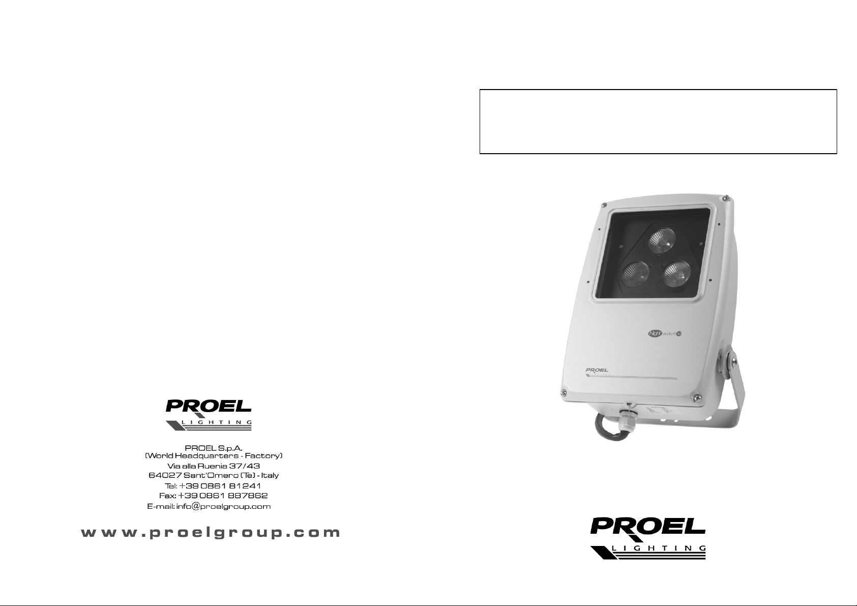
MANUALE UTENTE – USER’S MANUAL
PLAT50
NIGHTWAVE 50
Page 2
DESCRIZIONI DEL PRODOTTO
La presente unità è un sistema di missaggio con DMX-512 RGB a colori per illuminazione da
esterno con grado di protezione IP65. Grazie all’utilizzo di un controller DMX, questa unità
comprende un dimmer a 3 canali che, tramite il DMX, controlla 3 lampade PLLP5012D da
12V/50W. Queste tre lampade miscelate offrono un’ampia gamma di colori.
SPECIFICHE TECNICHE
Alimentazione: AC 230V~50Hz
Lampada: 3 x 64824 FL 220V/50W - Osram
Fusibile: 3.15A/250V
Peso: 4,5 Kg
Dimensione: mm. 390x270x120
ISTRUZIONI
1. Inserire presa di alimentazione generale 230V o 120V per il modello PLAT50US
2. Collegare un controller DMX all’unità tramite i cavi XRL a 3-pin.
3. Seguire attentamente l’impostazione del commutatore delle luci e la modalità di funzionamento
per gli effetti luce desiderati.
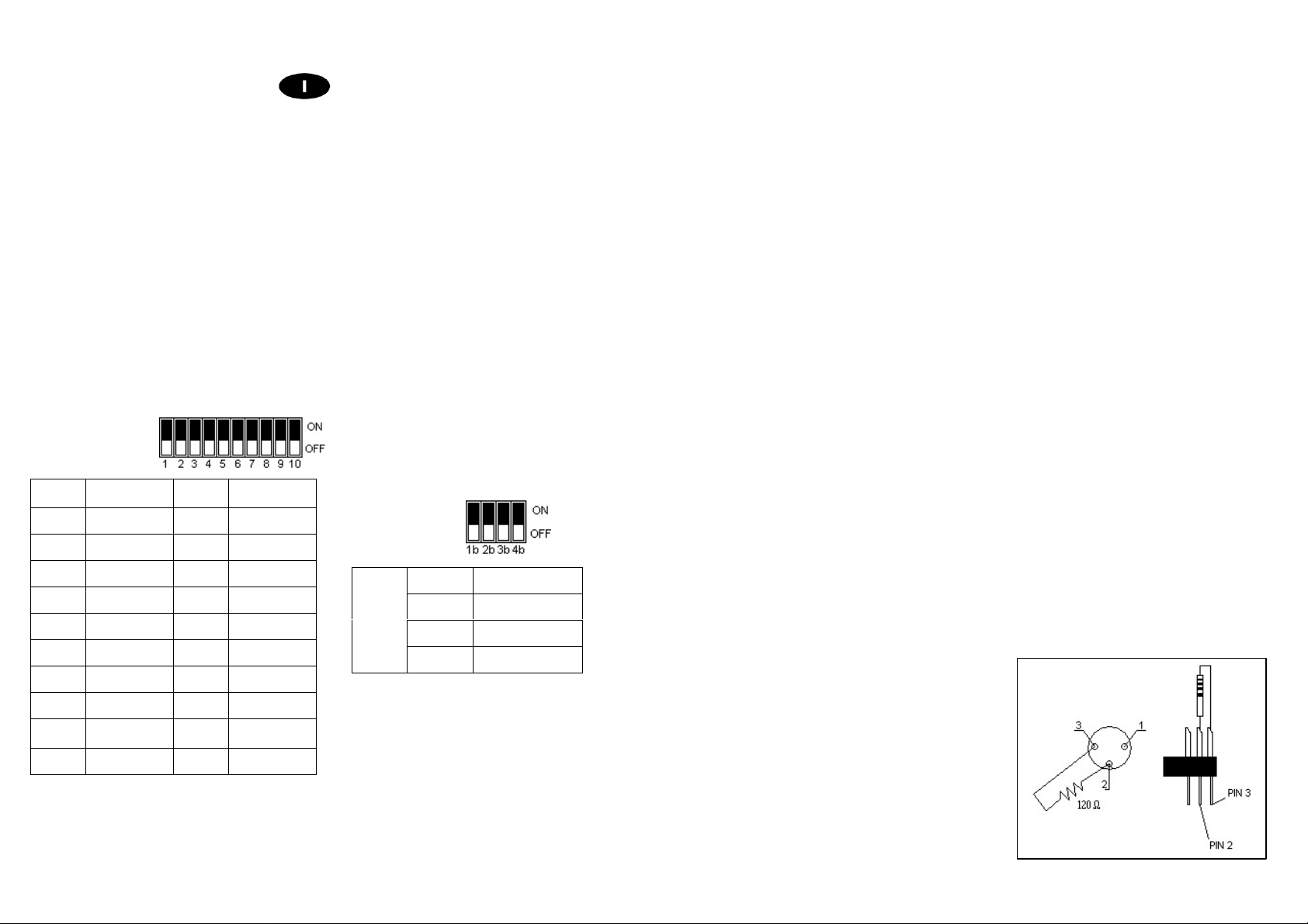
DMX Address Table
START
SWITCH ON
CH
1 1 11 1,2,4
2 2 12 3,4
3 1,2 13 1,3,4
4 3 14 2,3,4
5 1,3 15 1,2,3,4
6 2,3 : :
7 1,2,3 : :
8 4 : :
9 1,4 511
10 2,4 512 10
START
CH
SWITCH ON
1,2,3,4,5,
6,7,8,9
Operating Mode
Switch 1b Color
Switch 2b Color & Bright
MODE
Switch 3b RGB
Switch 4b
Test
APPENDIX:
The color and the intensity can be changed according to the following table:
DMX Value
(Decimal)
0 0 0 0 Black
1-2 100 0 0 Red
3-33 100 (N-2)x3 0 *
34 100 100 0 Red and Green
35-65 100-(N-34)x3 100 0 *
66-69 0 100 0 Green
70-100 0 100 (N-69)x3 *
101 0 100 100 Green and Blue
102-132 0 100-(N-101)x3 100 *
133-136 0 0 100 Blue
137-167 (N-136)x3 0 100 *
168 100 0 100 Red e Blue
169-199 100 0 100-(N-168)x3 *
200-206 100 (N-199)x6 (N-199)x12 *
207 100 50 100 *
208-210 100-(N-207)x12 50+(N-207)x12 100 *
211 50 100 100 *
212-215 50-(N-211)x6 100 100-(N-211)x12 *
216-218 25-(N-215)x6 100 50-(N-215)x6 *
219-222 (N-217)x6 100 25+(N-219)x6 *
223-225 38+(N-223)x6 100 (N-221)x6 *
226-228 50+(N-225)x12 100 25+(N-225)x6 *
229 100 100 50 *
230-232 100 100-(N-229)x12 50+(N-229)x12 *
233 100 50 100 *
234-236 100-(N-233)x12 50-(N-233)x6 100 *
237 50 25 100 *
238-240 50-(N-237)x6 25-(N-237)x6 100 *
241-244 25-(N-239)x6 (N-239)x6 100 *
245-247 (N-243)x6 (N-239)x6 100 *
248-251 25+(N-247)x6 50+(N-247)x12 100 *
252-254 50+(N-251)x12 100 100 *
255 100 100 100 White
NOTE:
1. "N" denotes DMX value (0-255). For example: If DMX value is 239, blue intensity will be 50(239-237)x6=38%, red intensity will be 25-(239-237)x6=13%, green intensity be 100%.
2. "*" denotes unnameable colour.
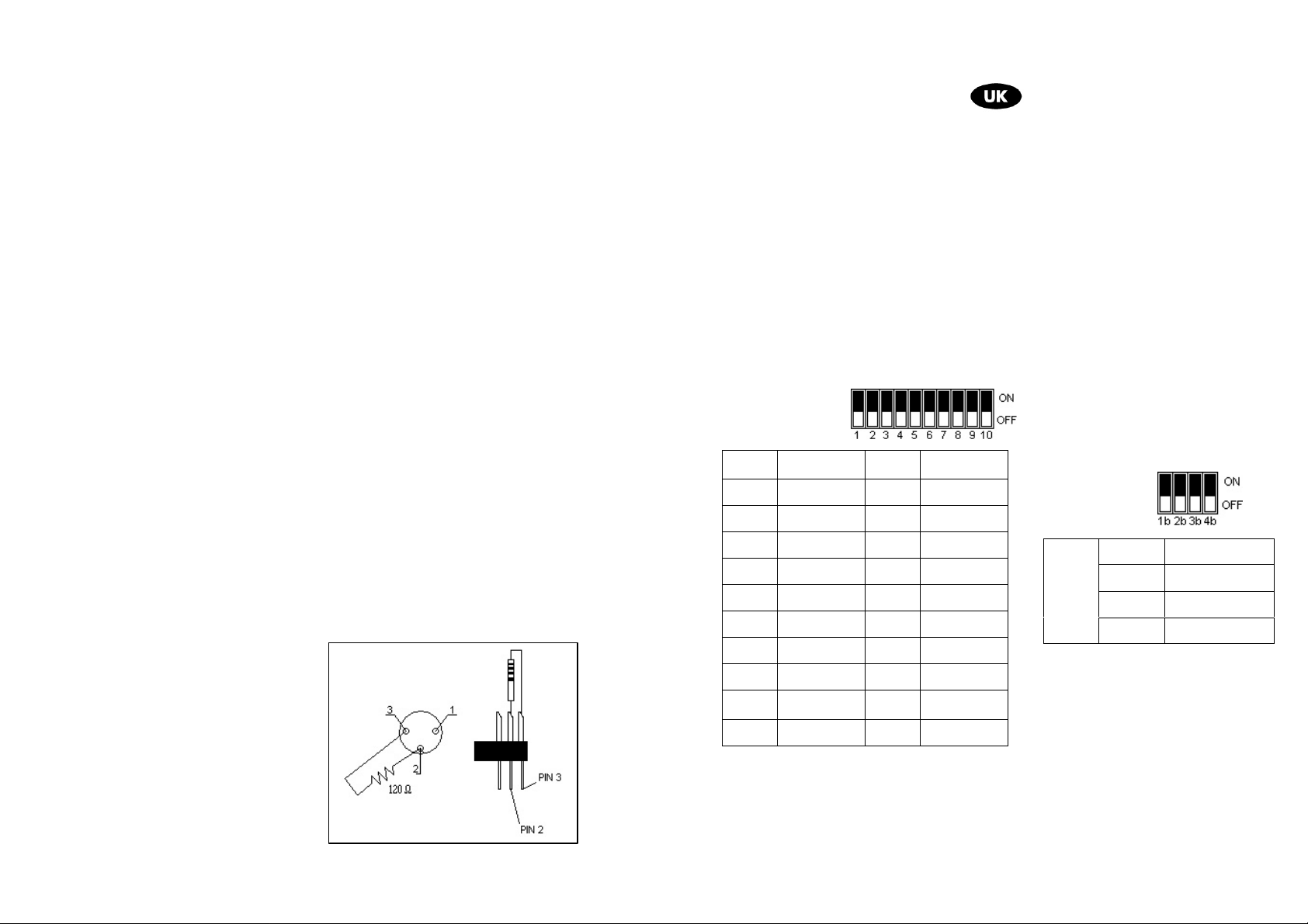
DMX TERMINATION:
For all installation, having long signal cables or in
the presence of electrical noise, for example a
discotheque, it is recommended practice to use a
DMX terminator: this assist in preventing corruption
of the digital control signal by external noise. The
DMX terminator is simply an XLR connector with a
120Ω (Ohm) resistor connected across pins 2 and
3, which is then plugged into the DIGITAL THRU
socket on the last projector in the chain. The
connections are illustrated on the right.
Red
(Intensity 0-100%)
Green
(Intensity 0-100%)
Blue
(Intensity 0-100%)
Colour
Page 3
SETTINGS
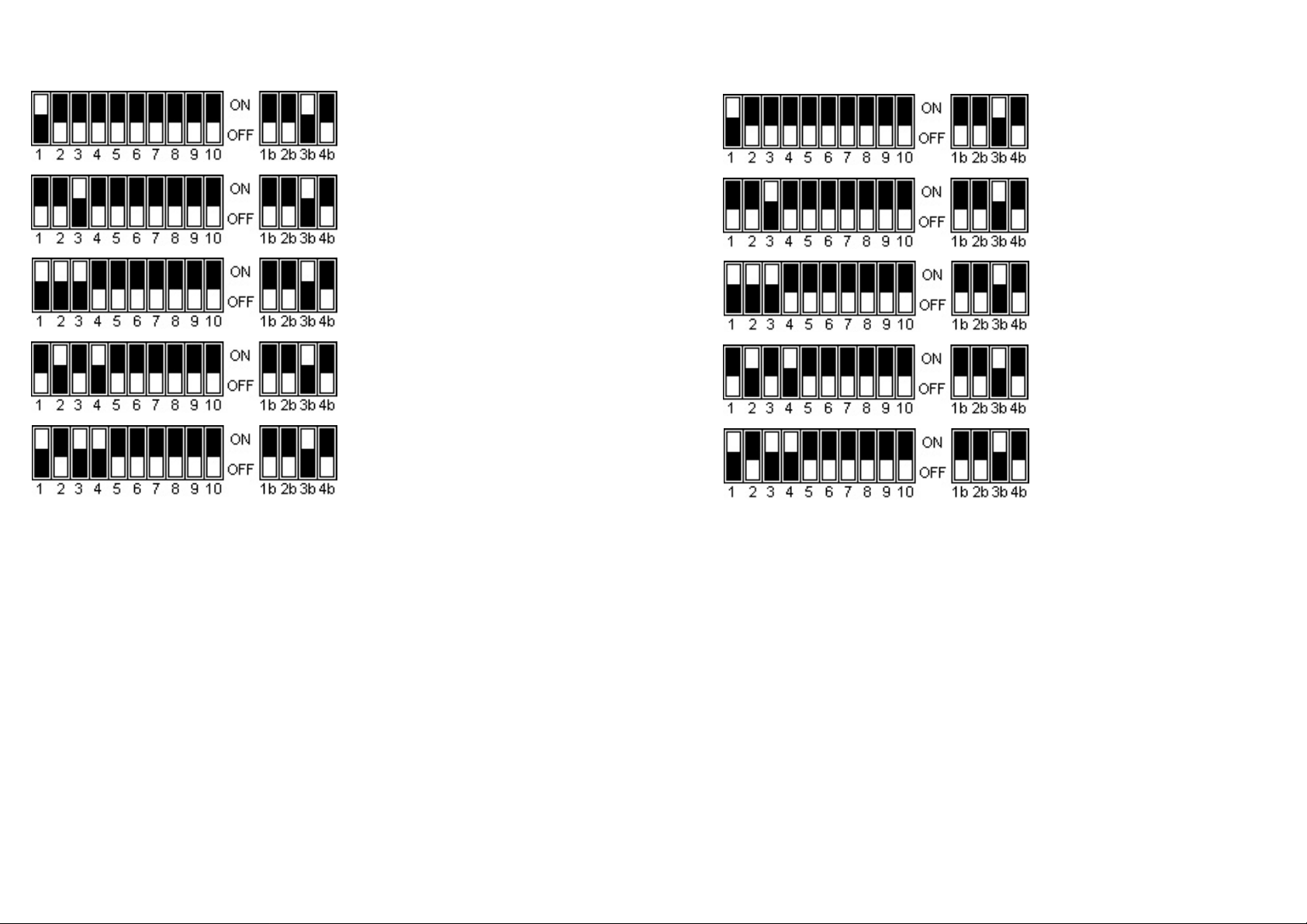
1st lamp
2nd lamp
3rd lamp
4th lamp
5th lamp
4. You can select desired operating mode from Color/Color & Bright/RGB modes.
• COLOR Modr: Assign MODE dip switch 1b to the “ON” position, this pack is set to Color
Mode. The output of the color will be controlled by one DMX channel with the use of a
DMX controller. 0 will give no output and 100 will give you full output.
• COLOR & BRIGHT Modr: Assign MODE dip switch 2b to the “ON” position, this pack is
set to Color & Bright Mode. The output of the color will be controlled by one DMX channel
and the bright will be controlled by another DMX channel.
• RGB Modr: Assign MODE dip switch 3b to the “ON” position, this pack is set to RGB
mode. The output of the blue lighting effect will be controlled by the first DMX channel, the
red will be controlled by the second DMX channel and the green by the third DMX
channel.
• TEST Modr: Assign MODE dip switch 4b to the “ON” position, this pack is set to Test
Mode. The output of the color will be controlled by itself.
CAUTION
5. This product must be earthed.
6. Very hot lamp, wait at least 15 minutes before opening the covers and removing lamp from the
fixture.
7. Disconnect the main power before opening the cover.
8. This product must be installed by a qualified electrician in accordance with all applicable
regulations.
IMPOSTAZIONI
1° faro
2° faro
3° faro
4° faro
5° faro
4. E’ possibile selezionare la modalità di funzionamento desiderata tramite Color/Color e
Bright/RGB.
• Modalità COLOR: Assegnando all’interruttore MODE Switch 1b la posizione ON, la
modalità Color viene impostata. L’emissione del colore viene controllata da un canale
DMX con l’utilizzo di un controller DMX. 0 indica l’assenza di emissione, 100 l’emissione
totale.
• Modalità COLOR & BRIGHT: Assegnando all’interruttore MODE Switch 2b la posizione
“ON”, la modalità Color & Bright viene attivata. L’emissione del colore verrà regolata da
un canale DMX e la luminosità da un altro.
• Modalità RGB: MODE Switch 3b in posizione “ON” consente di attivare la modalità RGB.
L’emissione dell’effetto luce blu verrà regolata dal primo canale DMX, il rosso dal secondo
e il verde dal terzo canale DMX.
• Modalità TEST: MODE Switch 4b in posizione “ON” attiva la modalità TEST. L’emissione
AVVERTENZE
5. Questo prodotto deve essere collegato a massa.
6. Lampada molto calda, attendere almeno 15 minuti prima di procedere all’apertura del coperchio
7. Disconnettere l’alimentazione generale prima di aprire il coperchio.
8. E’ necessario che il prodotto venga installato da elettricisti qualificati secondo le norme di
del colore verrà regolata autonomamente.
e alla rimozione della lampada dall’impianto.
applicazione dello stesso.
Page 4
APPENDICE
E’ possibile modificare il colore e l’intensità in base allo schema seguente:
Valore DMX
(Decimale)
0 0 0 0 Nero
1-2 100 0 0 Rosso
3-33 100 (N-2)x3 0 *
34 100 100 0 Rosso e Verde
35-65 100-(N-34)x3 100 0 *
66-69 0 100 0 Verde
70-100 0 100 (N-69)x3 *
101 0 100 100 Verde e Blu
102-132 0 100-(N-101)x3 100 *
133-136 0 0 100 Blu
137-167 (N-136)x3 0 100 *
168 100 0 100 Rosso e Blu
169-199 100 0 100-(N-168)x3 *
200-206 100 (N-199)x6 (N-199)x12 *
207 100 50 100 *
208-210 100-(N-207)x12 50+(N-207)x12 100 *
211 50 100 100 *
212-215 50-(N-211)x6 100 100-(N-211)x12 *
216-218 25-(N-215)x6 100 50-(N-215)x6 *
219-222 (N-217)x6 100 25+(N-219)x6 *
223-225 38+(N-223)x6 100 (N-221)x6 *
226-228 50+(N-225)x12 100 25+(N-225)x6 *
229 100 100 50 *
230-232 100 100-(N-229)x12 50+(N-229)x12 *
233 100 50 100 *
234-236 100-(N-233)x12 50-(N-233)x6 100 *
237 50 25 100 *
238-240 50-(N-237)x6 25-(N-237)x6 100 *
241-244 25-(N-239)x6 (N-239)x6 100 *
245-247 (N-243)x6 (N-239)x6 100 *
248-251 25+(N-247)x6 50+(N-247)x12 100 *
252-254 50+(N-251)x12 100 100 *
255 100 100 100 Bianco
NOTE
1. "N" indica il valore del DMX (0-255). Per esempio: Se il valore del DMX è 239, l’intensità del blu
sarà 50-(239-237)x6=38%, l’intensità del rosso sarà 25-(239-237)x6=13%, l’intensità del verde
sarà 100%.
2. "*" indica il colore anonimo.
TERMINAZIONE SEGNALE DMX:
Per installazioni dove il cavo di segnale deve
percorrere lunghe distanze o dove vi sono disturbi
elettrici, per esempio in discoteca, è consigliato
l’uso di una terminazione DMX. Il terminatore DMX
è semplicemente un connettore XLR con collegato
ad esso una resistenza da 120Ω (Ohm) tra i piedini
2 e 3. La resistenza viene innestata nella presa
DIGITAL THRU dell’ultimo proiettore della catena.
La connessione è illustrata a destra.
Rosso
(Intensità 0-100%)
Verde
(Intensità 0-100%)
Blu
(Intensità 0-100%)
Colore
PRODUCT DESCRIPTIONS
This unit is a DMX-512 RGB colour mixing system suitable for external use with IP65 protection
degree. Thanks to the use of a DMX controller, this unit serves as a 3 channel dimmer pack which
controls 3 PLLP5012D 12V/50W lamps by DMX. These three mixed lamps can provide a huge
range of colours.
TECHNICAL SPECIFICATIONS
Power Input: AC 230V~50Hz
Lamp type: 3 x 64824 FL 220V/50W - Osram
Fuse: 3.15A/250V
Weight: 4,5 Kg
Size: mm. 200x153x134
PRODUCT INSTRUCTIONS
1. Plug the main power, 230v or 120v power switch for PLAT50US model.
2. Plug in a DMX controller to your unit via 3-pin XRL cables.
3. Please follow the Dip Switch setting and operating mode for desired lighting effect.
DMX Address Table
START
SWITCH ON
CH
1 1 11 1,2,4
2 2 12 3,4
3 1,2 13 1,3,4
4 3 14 2,3,4
5 1,3 15 1,2,3,4
6 2,3 : :
7 1,2,3 : :
8 4 : :
9 1,4 511
10 2,4 512 10
START
CH
SWITCH ON
1,2,3,4,5,
6,7,8,9
Operating Mode
Switch 1b Colour
Switch 2b Color & Bright
MODE
Switch 3b RGB
Switch 4b
Test
 Loading...