

Page 1
USER MANUAL
NEOS10PX
passive loudspeaker
KEY FEATURES
• Premium transducers
• Rotatable asymmetric HF horn
• HF driver protec on
• Plywood cabinets with die-cast handles, dual-angle pole holder and mul ple fl ying points
INTRODUCTION
NEOS PX series represents the highest expression of PROEL GROUP Research & Development applied in loudspeaker systems. A natural evolu on
of the NEOS Series, it incorporates the latest technologies developed by PROEL in advanced sound reinforcement systems able to provide premium
sound, maximum performance and up-to-date features.
The NEOS PX are designed for the use both as high-performance mobile systems for live applica ons and for advanced fi xed installa ons.
The NEOS PX are able to provide an excep onal sound defi ni on together with very high dynamics and low distor on in an ultra-compact
package.
The NEOS PX passive fi lters are provided with a protec on on circuit for the HF driver, which has a two-step opera on: the fi rst step reduces the
power accordingly to the music content and without an audible eff ect; if a too high power level is present for a long period of me, the second
step shut the HF driver off .
TECHNICAL SPECIFICATION
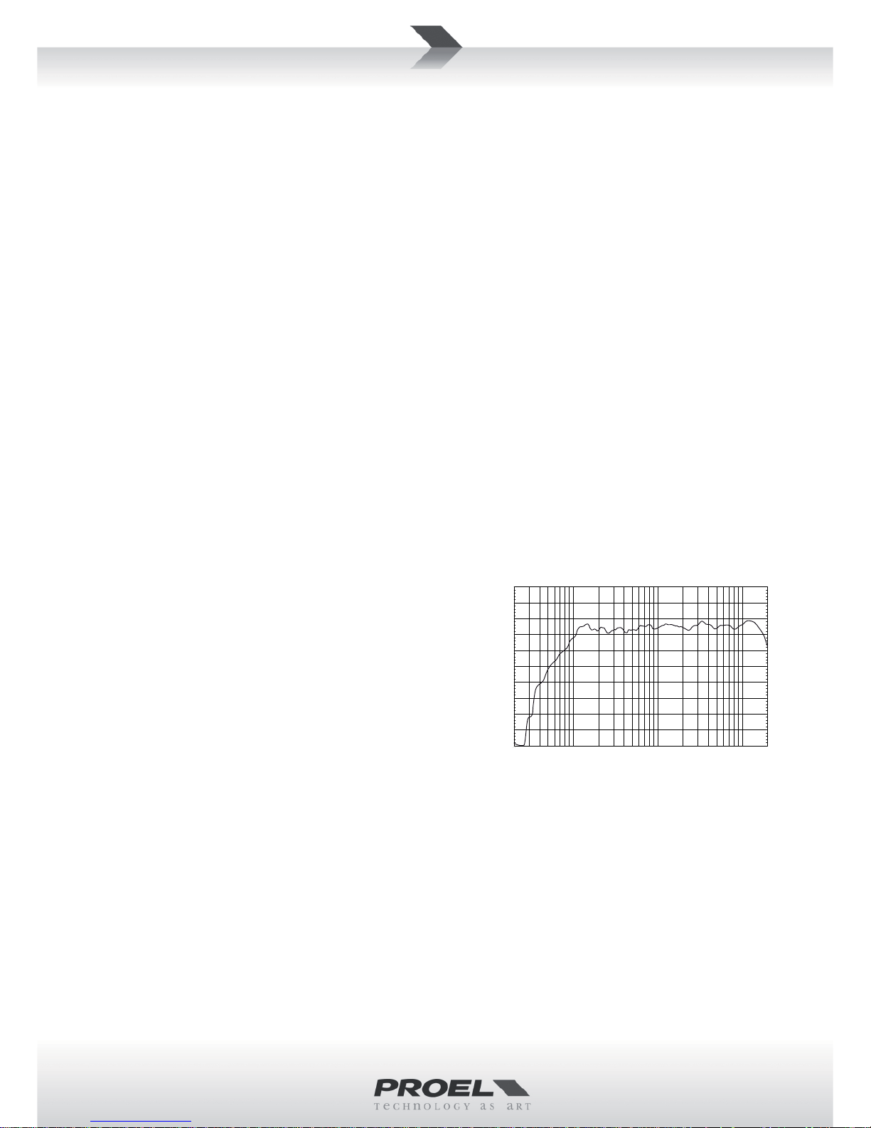
AcousƟ cal Frequency Response Diagram
System type Full range 2-way, vented
Low frequency driver 10’’ woofer - 2” VC
High frequency driver 1’’ compression driver - tanium diaphragm
Frequency response 70 Hz - 20 kHz
Horn type Asymmetrical rotatable horn
Coverage 100°>80° H x 60° V
Max SPL 124 dB
Electrical
Nominal Impedance 8 ohm
Power Handling Con nuous 250 W
Power Handling Peak 500 W
Sensi vity 97 dBspl @ 1W / 1m
Passive Crossover Frequency 2500 Hz
Connectors IN - LINK: Speakon® (NL4MP)
Controls FULL-RANGE / BI-AMP opera on (internal jumper)
Mechanical
Construc on 15 and 18 mm birch plywood
Finish An -scratch black paint
Flying hardware 4 x M10 - top, bo om, rear
Trapezoidal taper 10°
Monitor taper 42°
Pole holder 1 bo om dual angle (0° / 7.5°)
Dimensions (W x H x D) 355 x 520 x 310 mm
Weight 16 kg (35.2 lbs)
10k5k2k
1k
500200100502020 20kHz
110.0
dBSPL
100.0
90.0
80.0
70.0
60.0
Page 2
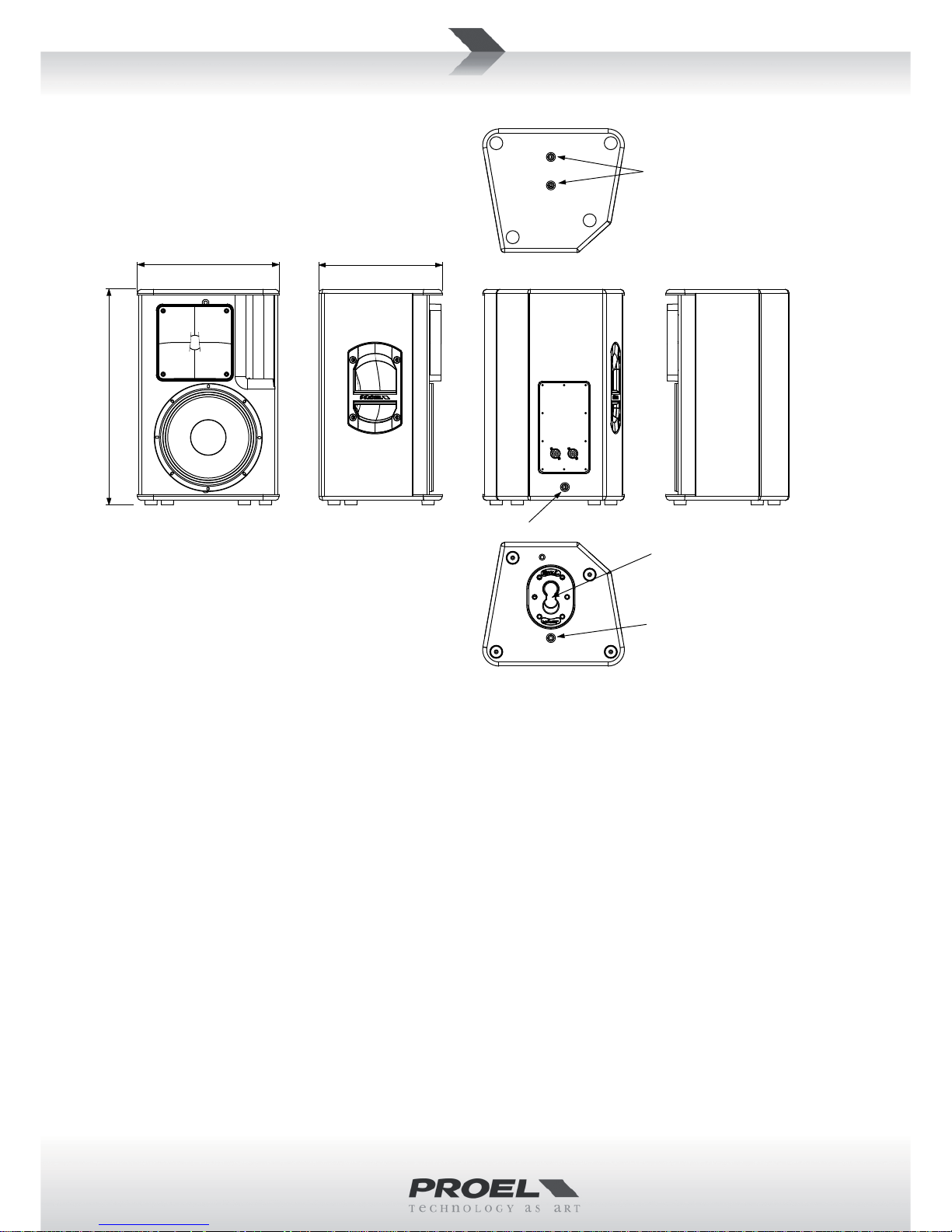
MECHANICAL DRAWING
35.0 cm
13.8"
30.5 cm
12"
53.0 cm
20.9"
Dual Angle Pole Holder
M10 Flying Point
M10 Flying Point
M10 Flying Point
OPTIONAL ACCESSORIES
ASO25 2 in 4 out analog loudspeaker processor for speaker suspending:
PC240 2 in 4 out digital loudspeaker processor PLH295 M10 Ø 50 mm Truss mount coupler
PC260 2 in 6 out digital loudspeaker processor AC169A M10 black shoulder eyebolt
COVERNE10 Loudspeaker so bag AC171 L = 75 cm / 30 inch Aircra cable sling
FRE300BK Loudspeaker ground stand AC172 L = 1.5 m / 4.9 Aircra cable sling
KP210BK Sub-Speaker pole AC173 Screw pin anchor shackle
KPPTL10 Loudspeaker wall stand
KPTFL10PB Loudspeaker free aiming ground stand
NL4FX Neutrik Speakon® PLUG
see www.proel.com for detailed descrip on and other available accessories.
SPARE PARTS
NL4MP Neutrik Speakon® panel socket
91CR0062 Crossover module
98NEOS10WZ8 10’’ woofer - 2” VC
98DRICN8 1’’ compression driver - tanium diaphragm
Page 3

REAR PANEL
INPUT - External amplifi er power input. The signal is fi ltered by a passive crossover. The connec ons depend by the confi gura on se ngs
accordingly the following table:
INPUT
FULL RANGE BI-AMP
1+ / 1- INPUT 1+ / 1- LOW
2+ / 2- INTERNALLY N.C. 2+ / 2- HIGH
LINK - Power signal output, to connect the unit to another speaker. The INPUT and LINK connectors are parallel to each other.
PRODUCT LABEL - In this label are wri en the most important data informa on about the passive loudspeaker, model, impedance, maximum
applicable con nuous power, serial number.
FULL RANGE / BI-AMP MODE - The speaker system can operate both in FULL RANGE and BI-AMP mode:
In FULL RANGE mode a built- in crossover fi lter allows the loudspeaker to be powered by a single amplifi er.
The BI-AMP mode requires a dedicated amplifi er for each speaker (woofer and HF driver), even if the internal crossover is not excluded we
recommend the use of an external crossover or processor before the amplifi ers.
The mode selec on can be done by an internal jumper (see fi gure 1), which can be accessible by removing the rear connec on plate. The factory
se ng is FULL-RANGE mode.
FIGURE 1: TO SET THE LOUDSPEAKER AS BI-AMP,
REMOVE THE REAR PANEL, LOCATE THE JUMPER AND
MOVE IT IN THE OTHER SIDE OF THE CROSSOVER
CIRCUIT.
Page 4

LIMITED WARRANTY
Proel warrants all materials, workmanship and proper opera on of this product for a period of two years from the original date of purchase. If any defects are found
in the materials or workmanship or if the product fails to func on properly during the applicable warranty period, the owner should inform about these defects the
dealer or the distributor, providing receipt or invoice of date of purchase and defect detailed descrip on. This warranty does not extend to damage resul ng from
improper installa on, misuse, neglect or abuse. Proel S.p.A. will verify damage on returned units, and when the unit has been properly used and warranty is s ll
valid, then the unit will be replaced or repaired. Proel S.p.A. is not responsible for any “direct damage” or “indirect damage” caused by product defec veness.
• This unit package has been submi ed to ISTA 1A integrity tests. We suggest you control the unit condi ons immediately a er unpacking it.
• If any damage is found, immediately advise the dealer. Keep all unit packaging parts to allow inspec on.
• Proel is not responsible for any damage that occurs during shipment.
• Products are sold “delivered ex warehouse” and shipment is at charge and risk of the buyer.
• Possible damages to unit should be immediately no fi ed to forwarder. Each complaint for package tampered with should be done within eight days from product
receipt.
SAFETY INSTRUCTIONS
– To reduce the risk, close supervision is necessary when the product is used near children.
– Protect the apparatus from atmospheric agents and keep it away from water, rain and high humidity places.
– This product should be site away from heat sources such as radiators, lamps and any other device that generate heat.
– This product should be located so that its loca on or posi on does not interfere with its proper ven la on and hea ng dissipa on.
– Care should be taken so that objects and liquids do not go inside the product.
– The product should be connected to a power supply mains line only of the type described on the opera ng instruc ons or as marked on the product. Connect the
apparatus to a power supply using only power cord included making always sure it is in good condi ons.
– WARNING: The mains plug is used as disconnect device, the disconnect device shall remain readily operable.
– Do not cancel the safety feature assured by means of a polarized line plug (one blade wider than the other) or with a earth connec on.
– Make sure that power supply mains line has a proper earth connec on.
– Power supply cord should be unplugged from the outlet during strong thunderstorm or when le unused for a long period of me.
CE CONFORMITY
Proel products comply with direc ve 2004/108/EC (EMC), as stated in EN 55103-1 and EN 55103-2 standards and with direc ve 2006/95/CE (LVD), as stated in EN
60065 standard.
PROEL S.p.A. (World Headquarter) - Via alla Ruenia 37/43 - 64027 Sant’Omero (Te) - ITALY
Tel: +39 0861 81241 Fax: +39 0861 887862 www.proel.com
 Loading...