

M1622USB
16-CH 4-BUS MIXER
WITH FX AND USB
USER MANUAL
MANUALE D'USO
BENUTZERHANDBUCH
NOTICE D'UTILISATION
MANUAL DE USO
ﻡﺍﺩﺧﺗﺳﻻﺍ ﻝﻳﻟﺩ
FCC COMPLIANCE NOTICE
This device complies with part 15 of the FCC rules. Opera on is subject to the following two condi ons:
(1) This device may not cause harmful interference, and
(2) this device must accept any interference received, including interference that may cause undesired opera on.
CAUTION: Changes or modifi ca ons not expressly approved by the party responsible for compliance could void
the user’s authority to operate the equipment.
NOTE: This equipment has been tested and found to comply with the limits for a Class B digital device, pursuant to
part 15 of the FCC Rules. These limits are designed to provide reasonable protec on against harmful interference in
a residen al installa on. This equipment generates, uses, and can radiate radio frequency energy and, if not installed
and used in accordance with the instruc on manual, may cause harmful interference to radio communica ons.
However, there is no guarantee that interference will not occur in a par cular installa on. If this equipment does
cause harmful interference to radio or television recep on, which can be determined by turning the equipment off
and on, the user is encouraged to try to correct the interference by one or more of the following measures:
• Reorient or relocate the receiving antenna.
• Increase the separa on between the equipment and receiver.
• Connect the equipment into an outlet on a circuit diff erent from that to which the receiver is connected.
• Consult the dealer or an experienced radio/TV technician for help.
This marking shown on the product or its literature, indicates that it should not be disposed with other household wastes at the end of
its working life. To prevent possible harm to the environment or human health from uncontrolled waste disposal, please separate this
from other types of wastes and recycle it responsibly to promote the sustainable reuse of material resources. Household users should
contact either the retailer where they purchased this product, or their local government offi ce, for details of where and how they can
purchase contract. This product should not be mixed with other commercial wastes for disposal.
The informa on contained in this publica on has been carefully prepared and checked. However no responsibility will be taken for any errors. All
rights are reserved and this document cannot be copied, photocopied or reproduced in part or completely without wri en consent being obtained
in advance from PROEL. PROEL reserves the right to make any aesthe c, func onal or design modifi ca on to any of its products without any prior
no ce. PROEL assumes no responsibility for the use or applica on of the products or circuits described herein.
termini e le condizioni del contra o di acquisto. Questo prodo o non deve essere smal to unitamente ad altri rifi u commerciali.
take this item for environmentally safe recycling. Business users should contact their supplier and check the terms and condi ons of the
The lightning fl ash with arrowhead symbol within an equilateral triangle is intended to alert the user to the presence of uninsulated
“dangerous voltage” within the product’s enclosure, that may be of suffi cient magnitude to cons tute a risk of electric shock to persons.
The exclama on point within an equilateral triangle is intended to alert the user to the presence of important opera ng and maintenance
(servicing) instruc ons in the literature accompanying the appliance.
Il marchio riportato sul prodo o o sulla documentazione indica che il prodo o non deve essere smal to con altri rifi u domes ci al
termine del ciclo di vita. Per evitare eventuali danni all’ambiente si invita l’utente a separare questo prodo o da altri pi di rifi u e di
riciclarlo in maniera responsabile per favorire il riu lizzo sostenibile delle risorse materiali. Gli uten domes ci sono invita a conta are
il rivenditore presso il quale è stato acquistato il prodo o o l’uffi cio locale preposto per tu e le informazioni rela ve alla raccolta
diff erenziata e al riciclaggio per questo po di prodo o. Gli uten
Il simbolo del lampo con freccia in un triangolo equilatero intende avver re l'u lizzatore per la presenza di "tensioni pericolose" non isolate
all'interno dell'involucro del prodo o, che possono avere una intensità suffi ciente a cos tuire rischio di scossa ele rica alle persone.
Il punto esclama vo in un triangolo equilatero intende avver re l'u lizzatore per la presenza di importan istruzioni per l'u lizzo e la
manutenzione nella documentazione che accompagna il prodo o.
aziendali sono invita a conta are il proprio fornitore e verifi care i
Le informazioni contenute in questo documento sono state a entamente reda e e controllate. Tu avia non è assunta alcuna responsabilità per
eventuali inesa ezze. Tu i diri sono riserva e questo documento non può essere copiato, fotocopiato, riprodo o per intero o in parte senza
previo consenso scri o della PROEL. PROEL si riserva il diri o di apportare senza preavviso cambiamen e modifi che este che, funzionali o di
design a ciascun proprio prodo o. PROEL non assume alcuna responsabilità sull’uso o sul l’applicazione dei prodo o dei circui qui descri .
Hausmüll entsorgt werden darf. Aus Umweltschutzgründen bi en wir den Anwender, das Gerät von anderem Müll getrennt zu entsorgen
und dem Recycling zuzuführen, damit die Rohstoff e umweltverträglich wiederverwertet werden können. Private Anwender wenden sich
dazu bi e an den Händler, bei dem sie das Produkt gekau haben, oder an eine örtliche Behörde, die Informa onen zur Mülltrennung
und zum Recycling dieser Art von Geräten geben kann. Gewerbliche Anwender werden gebeten, sich an den Zulieferer zu wenden und
die Vertragsbedingungen des Kaufvertrags zu überprüfen. Das Gerät darf nicht zusammen mit anderem Gewerbemüll entsorgt werden.
Das Symbol mit einem Pfeilblitz in einem gleichsei gen Dreieck warnt den Anwender vor „gefährlicher Spannung“ ohne Isolierung im
Gehäuse des Geräts. Diese kann hoch genug sein, um Stromschlaggefahr zu verursachen.
Das Ausrufezeichen in einem gleichsei gen Dreieck weist den Anwender auf wich ge Anweisungen zum Gebrauch und zur Instandhaltung
des Geräts in den beiligenden Unterlagen hin.
Die Angaben in diesem Dokument wurden sorgfäl g zusammengestellt und kontrolliert. Für mögliche Ungenauigkeiten übernehmen wir dennoch
keine Ha ung. Alle Rechte vorbehalten. Das Dokument darf ohne vorherige schri liche Genehmigung von PROEL nicht ganz oder in Teilen kopiert
oder reproduziert werden. PROEL behält sich das Recht vor, ohne Vorankündigung Änderungen an der Gestaltung, an den Funk onen oder
am Design aller ihrer Produkte vorzunehmen. PROEL ha et nicht für den Gebrauch oder die Verwendung der hier beschriebenen Geräte oder
elektrischen Systeme.
La marque reportée sur le produit ou sur la documenta on indique que l'appareil ne doit pas être éliminé avec d'autres déchets domes ques au
terme du cycle de sa vie. Afi n d'éviter tout dommage à l'environnement, l'u lisateur est invité à séparer cet appareil des autres types de déchets
et de le recycler de manière responsable pour favoriser la réu lisa on durable des ressources matérielles. Les u lisateurs domes ques sont invités
à contacter le revendeur où l'appareil a été acheté ou le service local préposé afi n d'obtenir toutes les informa ons rela ves au tri sélec f et au
du contrat d'achat. Cet appareil ne doit pas être éliminé avec d'autres déchets commerciaux.
recyclage pour ce type de produit. Les u lisateurs des entreprises sont invités à contacter leur fournisseur et à vérifi er les termes et les condi ons
Le symbole d'un éclair avec une fl èche dans un triangle équilatéral est des né à aver r l'u lisateur de la présence de « tensions dangereuses » non
isolées dans le boî er de l'appareil, lesquelles peuvent avoir une intensité suffi sante pour cons tuer un risque de choc électrique pour les personnes.
Le point d'exclama on dans un triangle équilatéral est des né à aver r l'u lisateur de la présence d'instruc ons importantes en vue de l'u lisa on
et de la maintenance de l'appareil dans la documenta on qui l'accompagne.
Les informa ons contenues dans ce document ont été rédigées avec a en on et contrôlées. Toutefois, la société PROEL n'assume aucune responsabilité en cas
d'inexac tude. Tous les droits sont réservés et ce document ne peut être copié, photocopié, reproduit en en er ou en par e, sans avoir obtenu au préalable le
consentement écrit de la société PROEL. PROEL se réserve le droit d'apporter, sans préavis, des changements et des modifi ca ons esthé ques, fonc onnelles ou
de design à tous ses produits. PROEL n'assume aucune responsabilité quant à l'u lisa on ou l'applica on des appareils ou des circuits décrits dans ce e no ce.
La marca reproducida en el producto o en la documentación indica que el producto no se debe eliminar con otros desechos domés cos al fi nal de su
ciclo de vida ú l. Para evitar posibles daños al medio ambiente se invita al usuario a separar este producto de otros pos de desechos y reciclarlo de
forma responsable para favorecer el uso sostenible de los recursos materiales. Los usuarios domés cos deben ponerse en contacto con el revendedor
donde han comprado el producto o la ofi cina local encargada, para conocer todas las informaciones correspondientes a la recogida selec va y al
contrato de compra. Este producto no se debe eliminar junto con otros desechos comerciales.
Las informaciones contenidas en este documento se han redactado y controlado atentamente. Sin embargo, el fabricante se exime de toda responsabilidad
por posibles inexac tudes. Todos los derechos reservados; por tanto este documento no se puede copiar, fotocopiar, reproducir total o parcialmente sin la
autorización previa escrita por parte de PROEL. PROEL si reserva el derecho de realizar sin previo aviso cambios esté cos, funcionales o de diseño a cualquier
producto suyo. PROEL no se asume ninguna responsabilidad por el uso o la aplicación de los productos o de los circuitos que se describen aquí.
.ﺩﺍﻭﻣﻟﺍ ﺭﺩﺎﺻﻣﻟ ﺔﻣﺍﺩﺗﺳﻣﻟﺍ ﻡﺍﺩﺧﺗﺳﻻﺍ ﺓﺩﺎﻋﺇ ﻰﻠﻋ ﻊﻳﺟﺷﺗﻠﻟ ﺔﻟﻭﺅﺳﻣ ﺔﻘﻳﺭﻁﺑ ﻩﺭﻳﻭﺩﺗ ﺓﺩﺎﻋﺇﻭ ﺕﺎﻳﺎﻔﻧﻟﺍ ﻥﻣ ﻯﺭﺧﻷﺍ ﻉﺍﻭﻧﻷﺍ ﻥﻋ ﺞﺗﻧﻣﻟﺍ ﺍﺫﻫ ﻝﺻﻔﺑ ﻡﻭﻘﻳ ﻥﺃ ﻡﺩﺧﺗﺳﻣﻟﺍ ﻥﻣ ﻭﺟﺭﻧ ﺔﺋﻳﺑﻟﺍ
ﺓﺩﺎﻋﺇﻭ ﺕﺎﻳﺎﻔﻧﻠﻟ ﺯﻳﺎﻣﺗﻣﻟﺍ ﻊﻣﺟﻟﺎﺑ ﺔﻘﻠﻌﺗﻣﻟﺍ ﺕﺎﻣﻭﻠﻌﻣﻟﺍ ﻊﻳﻣﺟ ﻥﻋ ﻝﻭﺅﺳﻣﻟﺍ ﻲﻠﺣﻣﻟﺍ ﺏﺗﻛﻣﻟﺍ ﻭﺃ ﻪﻧﻣ ﺞﺗﻧﻣﻟﺍ ءﺍﺭﺷ ﻡﺗ ﻱﺫﻟﺍ ﺔﺋﺯﺟﺗﻟﺍ ﻊﺋﺎﺑﺑ ﺍﻭﻠﺻﺗﻳ ﻥﺃ ﻝﺯﺎﻧﻣﻟﺍ ﻲﻓ ﻥﻳﻣﺩﺧﺗﺳﻣﻟﺍ ﻥﻣ ﻭﺟﺭﻧ
ﻊﻣ ﺞﺗﻧﻣﻟﺍ ﺍﺫﻫ ﻥﻣ ﺹﻠﺧﺗﻟﺍ ﻡﺩﻋ ﺏﺟﻳ .ءﺍﺭﺷﻟﺍ ﺩﻘﻋ ﻁﻭﺭﺷﻭ ﺩﻭﻧﺑ ﻥﻣ ﻖﻘﺣﺗﻟﺍﻭ ﻡﻬﺗﺻﺎﺧ ﺩﺭﻭﻣﻟﺎﺑ ﺍﻭﻠﺻﺗﻳ ﻥﺃ ﺕﺎﻛﺭﺷﻟﺍ ﻲﻓ ﻥﻳﻣﺩﺧﺗﺳﻣﻟﺍ ﻥﻣ ﻭﺟﺭﻧ .ﺕﺎﺟﺗﻧﻣﻟﺍ ﻥﻣ ﻉﻭﻧﻟﺍ ﺍﺫﻫ ﺭﻳﻭﺩﺗ
reciclaje para este po de producto. Se invita a las empresas a ponerse en contacto con su proveedor y controlar los términos y las condiciones del
El símbolo del relámpago con fl echa en un triángulo equilátero ene la intención de adver r al usuario respecto a la presencia de "tensiones peligrosas"
no aisladas dentro de la envoltura del producto, que pueden tener una intensidad sufi ciente para cons tuir riesgo de descarga eléctrica a las personas.
El punto exclama vo en un triángulo equilátero ene la intención de adver r al usuario respecto a la presencia de importantes instrucciones para el
uso y el mantenimiento en la documentación que acompaña el producto.
ﻰﻠﻋ ﺭﺍﺭﺿﺃ ﺔﻳﺃ ﺏﻧﺟﺗﻟ .ﻲﺿﺍﺭﺗﻓﻻﺍ ﻩﺭﻣﻋ ﺔﻳﺎﻬﻧ ﻲﻓ ﻯﺭﺧﻷﺍ ﺔﻳﻟﺯﻧﻣﻟﺍ ﺕﺎﻳﺎﻔﻧﻟﺍ ﻊﻣ ﻪﻧﻣ ﺹﻠﺧﺗﻟﺍ ﻡﺗﻳ ﻻ ﻥﺃ ﺏﺟﻳ ﺞﺗﻧﻣﻟﺍ ﻥﺄﺑ ﻖﺋﺎﺛﻭﻟﺍ ﻰﻠﻋ ﻭﺃ ﺞﺗﻧﻣﻟﺍ ﻰﻠﻋ ﺓﺭﻭﻛﺫﻣﻟﺍ ﺔﻣﻼﻌﻟﺍ ﻝﺩﺗ
.ﻯﺭﺧﻷﺍ ﺔﻳﺭﺎﺟﺗﻟﺍ ﺕﺎﻳﺎﻔﻧﻟﺍ
ﻝﻛﺷﻳﻟ ﺔﻳﻓﺎﻛ ﺓﻭﻘﺑ ﺩﻬﺟﻟﺍ ﺍﺫﻫ ﻥﻭﻛﻳ ﻥﺃ ﻥﻛﻣﻳﻭ ،ﺞﺗﻧﻣﻟﺍ ﺔﻳﻭﺎﺣ ﻝﺧﺍﺩ ﻝﻭﺯﻌﻣ ﺭﻳﻏ "ﺭﻳﻁﺧ ﺩﻬﺟ" ﺩﻭﺟﻭ ﻥﻣ ﻡﺩﺧﺗﺳﻣﻟﺍ ﺭﻳﺫﺣﺗ ﻲﻧﻌﻳ ﻉﻼﺿﻷﺍ ﻱﻭﺎﺳﺗﻣ ﺙﻠﺛﻣ ﻲﻓ ﻡﻬﺳﺑ ﻕﺭﺑﻟﺍ ﺯﻣﺭ ﻥﺇ
.ﺞﺗﻧﻣﻟﺍ ﻊﻣ ﺔﻘﻓﺭﻣﻟﺍ ﻖﺋﺎﺛﻭﻟﺍ ﻲﻓ ﺔﻧﺎﻳﺻﻟﺍﻭ ﻡﺍﺩﺧﺗﺳﻼﻟ ﺔﻣﻬﻣ ﺕﺎﻣﻳﻠﻌﺗ ﺩﻭﺟﻭ ﻥﻣ ﻡﺩﺧﺗﺳﻣﻟﺍ ﺭﻳﺫﺣﺗ ﻉﻼﺿﻷﺍ ﻱﻭﺎﺳﺗﻣ ﺙﻠﺛﻣ ﻲﻓ ﺏﺟﻌﺗﻟﺍ ﺔﻣﻼﻋ ﻲﻧﻌﺗ
ﺭﻳﻭﺻﺗ ﻭﺃ ﺦﺳﻧ ﺯﻭﺟﻳ ﻻﻭ ،ﺔﻅﻭﻔﺣﻣ ﻕﻭﻘﺣﻟﺍ ﻊﻳﻣﺟ .ﺎﻬﻳﻓ ﺔﻗﺩﻠﻟ ﺹﻘﻧ ﻱﺃ ﻥﻋ ﺔﻳﻟﻭﺅﺳﻣ ﺔﻳﺃ ﺔﻛﺭﺷﻟﺍ ﻝﻣﺣﺗﺗ ﻻ ،ﻙﻟﺫ ﻊﻣﻭ .ﺔﻳﺎﻧﻌﺑ ﺎﻬﻧﻣ ﻖﻘﺣﺗﻟﺍﻭ ﺔﻘﻳﺛﻭﻟﺍ ﻩﺫﻫ ﻲﻓ ﺓﺩﺭﺍﻭﻟﺍ ﺕﺎﻣﻭﻠﻌﻣﻟﺍ ﺩﺍﺩﻋﺇ ﻡﺗ
ﻭﺃ ﺔﻳﻔﻳﻅﻭ ﻭﺃ ﺔﻳﻟﺎﻣﺟ ﺕﻼﻳﺩﻌﺗﻭ ﺕﺍﺭﻳﻳﻐﺗ ﺔﻳﺃ ءﺍﺭﺟﺇ ﻲﻓ ﻖﺣﻟﺎﺑ PROEL ﻅﻔﺗﺣﺗ .PROEL ﻥﻣ ﺏﻭﺗﻛﻣﻭ ﻖﺑﺳﻣ ﺢﻳﺭﺻﺗ ﻰﻠﻋ ﻝﻭﺻﺣﻟﺍ ﻥﻭﺩﺑ ﺎﻳﺋﺯﺟ ﻭﺃ ﺎﻳﻠﻛ ﺔﻘﻳﺛﻭﻟﺍ ﻩﺫﻫ ﺝﺎﺗﻧﺇ ﺓﺩﺎﻋﺇ ﻭﺃ
.ﺔﻘﻳﺛﻭﻟﺍ ﻩﺫﻫ ﻲﻓ ﺓﺭﻭﻛﺫﻣﻟﺍ ﺭﺋﺍﻭﺩﻟﺍ ﻭﺃ ﺕﺎﺟﺗﻧﻣﻟﺍ ﻝﺎﻣﻌﺗﺳﺍ ﻭﺃ ﻡﺍﺩﺧﺗﺳﺍ ﻥﻋ ﺔﻳﻟﻭﺅﺳﻣ ﺔﻳﺃ PROEL ﻝﻣﺣﺗﺗ ﻻ .ﻖﺑﺳﻣ ﺭﺍﺫﻧﺇ ﻥﻭﺩﺑ ﺎﻬﺗﺎﺟﺗﻧﻣ ﻥﻣ ﺞﺗﻧﻣ ﻱﺃ ﻰﻠﻋ ﺔﻳﻣﻳﻣﺻﺗ
.ﺹﺎﺧﺷﻸﻟ ﺔﻳﺋﺎﺑﺭﻬﻛﻟﺍ ﺕﺎﻣﺩﺻﻟﺍ ﻲﻓ ﺏﺑﺳﺗﻠﻟ ﺍﺭﻁﺧ
INDEX
INDICE
FCC COMPLIANCE NOTICE . . . . . . . . . . . . . . . . . . . . . . . 2
TECHNICAL SPECIFICATIONS . . . . . . . . . . . . . . . . . . . . . 4
MECHANICAL DIMENSIONS . . . . . . . . . . . . . . . . . . . . . . 5
LAYOUT . . . . . . . . . . . . . . . . . . . . . . . . . . . . . . . . . . . . . . 6
CONTROL PANEL (FIG.1) . . . . . . . . . . . . . . . . . . . . . . . . . 7
CONTROL PANEL (FIG.2) . . . . . . . . . . . . . . . . . . . . . . . . . 8
CONNECTIONS . . . . . . . . . . . . . . . . . . . . . . . . . . . . . . . . 8
CONFIGURATION EXAMPLE . . . . . . . . . . . . . . . . . . . . . . 9
ENGLISH LANGUAGE . . . . . . . . . . . . . . . . . . . . . . . . . . . 10
SAFETY AND PRECAUTIONS . . . . . . . . . . . . . . . . . . . . . 10
IN CASE OF FAULT . . . . . . . . . . . . . . . . . . . . . . . . . . . . . 10
CE CONFORMITY . . . . . . . . . . . . . . . . . . . . . . . . . . . . . . 10
PACKAGING, SHIPPING AND COMPLAINT . . . . . . . . . . 10
WARRANTY AND PRODUCTS RETURN . . . . . . . . . . . . . 10
INSTALLATION AND DISCLAIMER . . . . . . . . . . . . . . . . . 10
POWER SUPPLY AND MAINTENANCE . . . . . . . . . . . . . 10
GENERAL INFORMATION . . . . . . . . . . . . . . . . . . . . . . . 11
OPERATING INSTRUCTIONS (FIG. 1 / 2) . . . . . . . . . . . . 11
INHALT
FCC COMPLIANCE NOTICE . . . . . . . . . . . . . . . . . . . . . . . 2
TECHNISCHE DATEN . . . . . . . . . . . . . . . . . . . . . . . . . . . . 6
MECHANISCHE ABMESSUNGEN . . . . . . . . . . . . . . . . . . . 8
LAYOUT . . . . . . . . . . . . . . . . . . . . . . . . . . . . . . . . . . . . . . 9
MISCHPULT (ABB.1) . . . . . . . . . . . . . . . . . . . . . . . . . . . 10
MISCHPULT (ABB.2) . . . . . . . . . . . . . . . . . . . . . . . . . . . 11
ANSCHLÜSSE . . . . . . . . . . . . . . . . . . . . . . . . . . . . . . . . . 11
KONFIGURATIONSBEISPIEL . . . . . . . . . . . . . . . . . . . . . . 12
DEUTSCHE SPRACHE . . . . . . . . . . . . . . . . . . . . . . . . . . . 31
SICHERHEITSHINWEISE . . . . . . . . . . . . . . . . . . . . . . . . . 31
BEI EINEM DEFEKT . . . . . . . . . . . . . . . . . . . . . . . . . . . . 31
CE-KONFORMITÄT . . . . . . . . . . . . . . . . . . . . . . . . . . . . . 31
VERPACKUNG, TRANSPORT UND REKLAMATIONEN . . 31
GARANTIE UND RÜCKGABE . . . . . . . . . . . . . . . . . . . . . 31
INSTALLATION UND VERWENDUNGSEINSCHRÄNKUNGEN . . 31
STROMVERSORGUNG UND INSTANDHALTUNG . . . . . 31
ALLGEMEINE INFORMATIONEN . . . . . . . . . . . . . . . . . . 32
BEDIENUNGSANLEITUNG (ABB. 1 / 2) . . . . . . . . . . . . . 32
FCC COMPLIANCE NOTICE . . . . . . . . . . . . . . . . . . . . . . . 2
SPECIFICHE TECNICHE . . . . . . . . . . . . . . . . . . . . . . . . . . 4
DIMENSIONI MECCANICHE . . . . . . . . . . . . . . . . . . . . . . 5
LAY-OUT . . . . . . . . . . . . . . . . . . . . . . . . . . . . . . . . . . . . . 6
PANNELLO DI CONTROLLO (FIG.1) . . . . . . . . . . . . . . . . . 7
PANNELLO DI CONTROLLO (FIG.2) . . . . . . . . . . . . . . . . . 8
CONNESSIONI . . . . . . . . . . . . . . . . . . . . . . . . . . . . . . . . . 8
ESEMPIO CONFIGURAZIONE . . . . . . . . . . . . . . . . . . . . . 9
LINGUA ITALIANA . . . . . . . . . . . . . . . . . . . . . . . . . . . . . 19
AVVERTENZE PER LA SICUREZZA . . . . . . . . . . . . . . . . . 19
IN CASO DI GUASTO . . . . . . . . . . . . . . . . . . . . . . . . . . . 19
CONFORMITÀ CE . . . . . . . . . . . . . . . . . . . . . . . . . . . . . . 19
IMBALLAGGIO, TRASPORTO E RECLAMI . . . . . . . . . . . 19
GARANZIE E RESI . . . . . . . . . . . . . . . . . . . . . . . . . . . . . 19
INSTALLAZIONE E LIMITAZIONI D’USO . . . . . . . . . . . . . 19
ALIMENTAZIONE E MANUTENZIONE . . . . . . . . . . . . . . 19
INFORMAZIONI GENERALI . . . . . . . . . . . . . . . . . . . . . . 20
ISTRUZIONI OPERATIVE (FIG. 1 / 2) . . . . . . . . . . . . . . . 20
INDEX
FCC COMPLIANCE NOTICE . . . . . . . . . . . . . . . . . . . . . . . 2
SPÉCIFICATIONS TECHNIQUES . . . . . . . . . . . . . . . . . . . . 6
DIMENSIONS MÉCANIQUES . . . . . . . . . . . . . . . . . . . . . . 8
LAY-OUT . . . . . . . . . . . . . . . . . . . . . . . . . . . . . . . . . . . . . 9
PANNEAU DE COMMANDE (FIG.1) . . . . . . . . . . . . . . . . 10
PANNEAU DE COMMANDE (FIG.2) . . . . . . . . . . . . . . . . 11
CONNEXIONS . . . . . . . . . . . . . . . . . . . . . . . . . . . . . . . . 11
EXEMPLE DE CONFIGURATION . . . . . . . . . . . . . . . . . . . 12
LANGUE FRANÇAISE . . . . . . . . . . . . . . . . . . . . . . . . . . 40
MISES EN GARDE DE SÉCURITÉ . . . . . . . . . . . . . . . . . . 40
EN CAS DE PANNE . . . . . . . . . . . . . . . . . . . . . . . . . . . . . 40
CONFORMITÉ CE . . . . . . . . . . . . . . . . . . . . . . . . . . . . . . 40
EMBALLAGE, TRANSPORT ET RÉCLAMATIONS . . . . . . 40
GARANTIES ET RETOURS . . . . . . . . . . . . . . . . . . . . . . . 40
INSTALLATION ET LIMITES D'UTILISATION . . . . . . . . . . 40
ALIMENTATION ET MAINTENANCE . . . . . . . . . . . . . . . 40
INFORMATIONS GÉNÉRALES . . . . . . . . . . . . . . . . . . . . 41
INSTRUCTIONS DE FONCTIONNEMENT (FIG. 1 / 2) . . 41
ÍNDICE
FCC COMPLIANCE NOTICE . . . . . . . . . . . . . . . . . . . . . . . 2
CARACTERÍSTICAS TÉCNICAS . . . . . . . . . . . . . . . . . . . . . 7
DIMENSIONES MECÁNICAS . . . . . . . . . . . . . . . . . . . . . . 8
LAY-OUT . . . . . . . . . . . . . . . . . . . . . . . . . . . . . . . . . . . . . 9
PANEL DE CONTROL (FIG.1) . . . . . . . . . . . . . . . . . . . . . 10
PANEL DE CONTROL (FIG.2) . . . . . . . . . . . . . . . . . . . . . 11
CONEXIONES . . . . . . . . . . . . . . . . . . . . . . . . . . . . . . . . . 11
EJEMPLO DE CONFIGURACION . . . . . . . . . . . . . . . . . . 12
IDIOMA ESPAÑOL . . . . . . . . . . . . . . . . . . . . . . . . . . . . . 49
ADVERTENCIAS PARA LA SEGURIDAD . . . . . . . . . . . . . 49
EN CASO DE AVERÍA . . . . . . . . . . . . . . . . . . . . . . . . . . . 49
CONFORMIDAD CE . . . . . . . . . . . . . . . . . . . . . . . . . . . . 49
EMBALAJE, TRANSPORTE Y RECLAMACIONES . . . . . . . 49
GARANTÍAS Y DEVOLUCIONES . . . . . . . . . . . . . . . . . . . 49
INSTALACIÓN Y LIMITACIONES DE USO . . . . . . . . . . . . 49
ALIMENTACIÓN Y MANTENIMIENTO . . . . . . . . . . . . . . 49
INFORMACIÓN GENERAL . . . . . . . . . . . . . . . . . . . . . . . 50
INSTRUCCIONES OPERATIVAS (FIG. 1 / 2) . . . . . . . . . . 50
4
ﺱﺭﻬﻔﻟﺍ
2 .................................... FCC COMPLIANCE NOTICE
7 ............................................................... ﺔﻳﻧﻘﺗﻟﺍ ﺕﺎﻔﺻﺍﻭﻣﻟﺍ
8 ................................................................ﺔﻳﻛﻳﻧﺎﻛﻳﻣﻟﺍ ﺩﺎﻌﺑﻷﺍ
9 .......................................................................... ﻡﻳﻣﺻﺗﻟﺍ
10 .......................................................(1 ﻝﻛﺷﻟﺍ) ﻡﻛﺣﺗﻟﺍ ﺔﺣﻭﻟ
11 .......................................................(2 ﻝﻛﺷﻟﺍ) ﻡﻛﺣﺗﻟﺍ ﺔﺣﻭﻟ
11 .....................................................................ﺕﻼﻳﺻﻭﺗﻟﺍ
12 ................................................... ﺔﺋﻳﻬﺗﻟﺍ ﻭﺃ ﻥﻳﻭﻛﺗﻟﺍ ﻥﻋ ﻝﺎﺛﻣ
58 ..........................................................................ﺔﻳﺑﺭﻌﻟﺍ
58 .................................................. ﺔﻣﻼﺳﻟﺎﺑ ﺔﺻﺎﺧﻟﺍ ﺕﺍﺭﻳﺫﺣﺗﻟﺍ
58 .................................................................ﻝﻁﻌﻟﺍ ﺔﻟﺎﺣ ﻲﻓ
58 ....................................................................CE ﺔﻘﺑﺎﻁﻣ
58 ............................................ ﻯﻭﺎﻛﺷﻟﺍﻭ ﻝﻘﻧﻟﺍﻭ ﻑﻳﻠﻐﺗﻟﺍﻭ ﺔﺋﺑﻌﺗﻟﺍ
58 ...............................................................ﺩﺋﺍﻭﻌﻟﺍﻭ ﻥﺎﻣﺿﻟﺍ
58 .............................................. ﻡﺍﺩﺧﺗﺳﻻﺍ ﻰﻠﻋ ﺩﻭﻳﻘﻟﺍﻭ ﺏﻳﻛﺭﺗﻟﺍ
58 ............................................................... ﺔﻧﺎﻳﺻﻟﺍﻭ ﺔﻳﺫﻐﺗﻟﺍ
59 .................................................................ﺔﻣﺎﻋ ﺕﺎﻣﻭﻠﻌﻣ
59 ............................................. (2 / 1 ﻝﻛﺷﻟﺍ) ﻝﻳﻐﺷﺗﻟﺍ ﺕﺎﻣﻳﻠﻌﺗ

TECHNICAL SPECIFICATIONS SPECIFICHE TECNICHE
MODEL M1622USB Connectors MODELLO M1622USB Conne ori
MONO INPUT CHANNELS CANALI INGRESSO MONO
Mic Input Sensi vity from 0 to -60 dBu
Mic Input Impedance 2 Kohm Impedenza Ingresso Mic 2 Kohm
Line Input Sensi vity from +20 to -40 dBu
Line Input Impedance 10 Kohm Impedenza Ingresso Line 10 Kohm
LO CUT 75Hz, 18dB/oct. FILTRO LO-CUT 75Hz, 18dB/oct.
EQ HIGH (shelving) ±15 dB @ 12KHz EQ ALTI (shelving) ±15 dB @ 12KHz
EQ MID (peaking) ±15 dB @ 2.5KHz from 100 Hz to 8 KHz EQ MEDI (peaking) ±15 dB @ 2.5KHz da 100 Hz a 8 KHz
EQ LOW (shelving) ±15 dB @ 80Hz EQ BASSI (shelving) ±15 dB @ 80Hz
STEREO INPUT CHANNELS CANALI INGRESSO STEREO
Mic Input Sensi vity from 0 to -40 dBu
Mic Input Impedance 2 Kohm Impedenza Ingresso Mic 2 Kohm
Line Input Sensi vity from +20 to -20 dBu
Line Input Impedance 10 Kohm Impedenza Ingresso Line 10 Kohm
EQ HIGH (shelving) ±15 dB @ 12 KHz EQ ALTI (shelving) ±15 dB @ 12KHz
EQ HI-MID (peaking) ±15 dB @ 3 KHz EQ MEDIO-ALTI (peaking) ±15 dB @ 3 KHz
EQ LO-MID (peaking) ±15 dB @ 500 Hz EQ MEDIO-BASSI (peaking) ±15 dB @ 500 Hz
EQ LOW (shelving) ±15 dB @ 80Hz EQ BASSI (shelving) ±15 dB @ 80Hz
MASTER SECTION SEZIONE MASTER
MAIN MIX nom. out level +4 dBu Balanced Jack / XLR-M Livello nom. MAIN MIX +4 dBu Jack Bilanciato / XLR-M
MAIN MIX INSERT 0 dBu TRS Jack INSERT MAIN MIX 0 dBu TRS Jack
MIX/AUX Assignable EQ graphic 7 band MIX/AUX EQ Assegnabile graphic 7 band
GROUP nom. out level +4 dBu Balanced Jack Livello nom. GROUP +4 dBu Jack Bilanciato
C.ROOM nom. out level 0 dBu Unbalanced Jack Livello nom. C.ROOM 0 dBu Jack Sbilanciato
AUX nom. out level 0 dBu Unbalanced Jack Livello nom. AUX 0 dBu Jack Sbilanciato
2 - TRK nom. out level 0 dBu Unbalanced Rca Livello nom. 2 - TRK OUT 0 dBu Rca Sbilanciato
2 - TRK nom. in level 0 dBu Unbalanced Rca Livello nom. 2 - TRK IN 0 dBu Rca Sbilanciato
PHONES min. impedance 32 ohm
PHONES max. out level (2x) 193 mW Livello max. PHONES (2x) 193 mW
USB IN/OUT, 16bit / 48KHz
DIGITAL EFFECT PROCESSOR - PROFEX DIGITAL EFFECT PROCESSOR - PROFEX
Presets 256 (16 presets x 16 varia ons) Presets 256 (16 preset x 16 variazioni)
A/D and D/A converters 24 bit A/D and D/A converters 24 bit
DSP resolu on 24 bit DSP resolu on 24 bit
Controls 2-digit display, PRESET dial, PEAK LED, TAP DELAY
and MUTE with switch, footswitch and LED
GENERAL SPECIFICATIONS SPECIFICHE GENERALI
Max level all outputs +22 dBu Livello Massimo Uscite +22 dBu
Crosstalk meas. at 1 KHz > 82 dB Diafonia mis. a 1 KHz > 82 dB
HUM & N unweighted < -93 dBu HUM & N non pesato < -93 dBu
THD+N at +4dB, 1kHz < 0,008 % THD+N a +4dB, 1kHz < 0,008 %
Dimensions (W x H x D) 465 x 91 x 462 mm Dimensioni (L x A x P) 465 x 91 x 462 mm
Weight 6.50 kg Peso 6,50 kg
POWER REQUIREMENTS ALIMENTAZIONE
Mains Supply Voltage: 110-240 VAC (±10%) 50 / 60 Hz
available with Europe mains cord (Shucko plug),
US mains cord (NEMA 5-15P plug),
UK mains cord (BS1363 plug)
Consump on 75 W Assorbimento 75 W
Balanced XLR-F
Balanced Jack
Balanced XLR-F
Balanced Jack
Stereo Jack
Type B
Sensibilità Ingresso Mic da 0 a -60 dBu
Sensibilità Ingresso Line da +20 a -40 dBu
Sensibilità Ingresso Mic da 0 a -40 dBu
Sensibilità Ingresso Line da +20 a -20 dBu
Impedenza min. PHONES 32 ohm
USB IN/OUT, 16bit / 48KHz
Controlli 2 display LED, sele ore PRESET, PEAK LED, TAP
DELAY e MUTE con tasto, pedale e LED
Tensione di Rete: 110-240 VAC (±10%) 50 / 60 Hz
disponibile con cavo rete Europa (spina Shucko),
cavo rete Sta Uni (spina NEMA 5-15P),
cavo rete Regno Unito (spina BS1363)
XLR-F Bilanciato
Jack Bilanciato
XLR-F Bilanciato
Jack Bilanciato
Jack Stereo
Tipo B
5

TECHNISCHE DATEN
MODELL M1622USB Anschlüsse
MONO-EINGANGSKANÄLE
Eingangsempfi ndlichkeit MIC
Eingangsimpedanz Mic
Eingangsempfi ndlichkeit
Eingangsimpedanz
FILTER LO-CUT
Hochfrequenz-EQ (Kuhschwanzfi lter)
MITTELFREQUENZ-EQ (Peakfi lter)
NIEDERFREQUENZ-EQ (Kuhschwanzfi lter)
Eingangsempfi ndlichkeit MIC
Eingangsimpedanz Mic
Eingangsempfi ndlichkeit
Eingangsimpedanz
Hochfrequenz-EQ (Kuhschwanzfi lter)
Mi elfrequenz-EQ (Peakfi lter)
MITTELFREQUENZ-EQ (Peakfi lter)
NIEDERFREQUENZ-EQ (Kuhschwanzfi lter)
Bemessungspegel MAIN MIX
INSERTBUCHSE MAIN MIX
Zuweisbarer MIX/AUX EQ
Bemessungspegel GRUPPE
Bemessungspegel C.ROOM
Bemessungspegel AUX
Bemessungspegel 2 - TRK OUT
Bemessungspegel 2 - TRK IN
Min. Impendanz PHONES
Max. Pegel PHONES
USB
DIGITAL-EFFEKT-PROZESSOR - PROFEX
Voreinstellungen
A/D und D/A Umwandler
DSP Aufl ösung
Regler
Maximalpegel der Ausgänge
Übersprechdämpfung bei 1 KHz > 82 dB
Restrauschen, nicht gewichtet < -93 dBu
THD+N bei +4dB, 1kHz < 0,008 %
Abmessungen (B x H x T) 465 x 91 x 462 mm
Gewicht 6,50 kg
Netzspannung: 110-240 VAC (±10%) 50 / 60 Hz
Leistungsaufnahme 75 W
6
von 0 bis -60 dBu
2 Kohm
von +20 bis -40 dBu
10 Kohm
75Hz, 18dB/oct.
±15 dB @ 12KHz
±15 dB @ 2.5KHz von 100 Hz bis 8 KHz
±15 dB @ 80Hz
STEREO-EINGANGSKANÄLE
von 0 bis -40 dBu
2 Kohm
von +20 bis -20 dBu
10 Kohm
±15 dB @ 12KHz
±15 dB @ 3 KHz
±15 dB @ 500 Hz
±15 dB @ 80Hz
MASTER-BEREICH
+4 dBu Klinkenstecker symmetrisch /
0 dBu TRS Klinkenstecker
7 Band Graphik
+4 dBu symmetrischer Klinkenstecker
0 dBu unsymmetrischer
0 dBu unsymmetrischer
0 dBu unsymmetrischer RCA (Cinch)
0 dBu unsymmetrischer RCA (Cinch)
32 Ohm
(2x) 193 mW
IN/OUT, 16bit / 48KHz
256 (16 presets (Voreinstellungen) x 16 Varia onen)
2 LED-Displays, Wahlschalter PRESET, PEAK LED, TAP DELAY und
MUTE mit Taste, Pedal und LED
ALLGEMEINE DATEN
STROMVERSORGUNG
verfügbar mit Netzkabel Europa ( Schukostecker),
Netzkabel USA (Stecker NEMA 5-15P),
Netzkabel Großbritannien (Stecker BS1363)
symmetrischer Klinkenstecker
symmetrischer Klinkenstecker
24 bit
24 bit
+22 dBu
symmetrischer XLR-F
symmetrischer XLR-F
XLR-M
Klinkenstecker
Klinkenstecker
Stereo-Klinkenstecker
Typ B
SPÉCIFICATIONS TECHNIQUES
MODÈLE M1622USB Connecteurs
CANAUX ENTRÉE MONO
Sensibilité Entrée Mic de 0 à -60 dBu
Impédance Entrée Mic 2 Kiloohms
Sensibilité Entrée Line de +20 à -40 dBu
Impédance Entrée Line 10 Kiloohms
FILTRE LO-CUT 75 Hz, 18 dB/oct.
EQ HAUTES (shelving) ±15 dB @ 12 KHz
EQ MOYENNES (peaking) ±15 dB @ 2.5 KHz de 100 Hz à 8 KHz
EQ BASSES (shelving) ±15 dB @ 80 Hz
CANAUX ENTRÉE STÉRÉO
Sensibilité Entrée Mic de 0 à -40 dBu
Impédance Entrée Mic 2 Kiloohms
Sensibilité Entrée Line de +20 à -20 dBu
Impédance Entrée Line 10 Kiloohms
EQ HAUTES (shelving) ±15 dB @ 12 KHz
EQ MOYENNES-HAUTES (peaking)
EQ MOYENNES-BASSES (peaking)
EQ BASSES (shelving) ±15 dB @ 80Hz
Niveau nominal MAIN MIX
INSERT MAIN MIX
MIX/AUX EQ A ribuable
Niveau nominal GROUP
Niveau nominal C.ROOM
Niveau nominal AUX
Niveau nominal 2 - TRK OUT
Niveau nominal 2 - TRK IN
Impédance min. PHONES 32 ohms
Niveau max. PHONES (2x) 193 mW
USB IN/OUT, 16bits /
DIGITAL EFFECT PROCESSOR - PROFEX
Presets 256 (16 preset x 16 varia ons)
A/D and D/A converters 24 bits
DSP resolu on 24 bits
Commandes 2 écrans LED, sélecteur PRESET, PEAK LED, TAP
Niveau maximal des sor es
Diaphonie mesurée à 1 KHz
HUM & N non pesé
THD+N a +4 dB, 1 kHz
Dimensions (L x H x P)
Poids 6,50 kg
Tension de réseau : 110-240 VAC (±10 %) 50 / 60 Hz
Absorp on 75 W
±15 dB @ 3 KHz
±15 dB @ 500 Hz
SECTION MASTER
+4 dBu Jack Symétrique/ XLR-M
0 dBu TRS Jack
graphic 7 band
+4 dBu Jack Symétrique
0 dBu Jack Asymétrique
0 dBu Jack Asymétrique
0 dBu RCA Asymétrique
0 dBu RCA Asymétrique
48KHz
DELAY et MUTE avec touche, pédale et LED
SPÉCIFICATIONS GÉNÉRALES
465 x 91 x 462 mm
ALIMENTATION
disponible avec câble de réseau Europe (fi che
Schuko), câble de réseau États-Unis (fi che NEMA
5-15P), câble de réseau Royaume-Uni (fi che
XLR-F Symétrique
Jack Symétrique
XLR-F Symétrique
Jack Symétrique
Jack Stéréo
Type B
+22 dBu
> 82 dB
< -93 dBu
< 0,008 %
BS1363)

CARACTERÍSTICAS TÉCNICAS
MODELO M1622USB Conectores
CANALES DE ENTRADA MONO
Sensibilidad entrada Mic de 0 a -60 dBu
Impedancia entrada Mic 2 Kohm
Sensibilidad entrada Line de +20 a -40 dBu
Impedancia entrada Line 10 Kohm
FILTRO LO-CUT 75 Hz, 18 dB/oct.
EQ ALTOS (shelving) ±15 dB @ 12KHz
EQ MEDIOS (peaking) ±15 dB @ 2.5KHz de 100 Hz a 8 KHz
EQ BAJOS (shelving) ±15 dB @ 80Hz
CANALES DE ENTRADA ESTÉREO
Sensibilidad entrada Mic de 0 a -40 dBu
Impedancia entrada Mic 2 Kohm
Sensibilidad entrada Line de +20 a -20 dBu
Impedancia entrada Line 10 Kohm
EQ ALTOS (shelving) ±15 dB @ 12KHz
EQ MEDIO-ALTOS (peaking)
EQ MEDIO-BAJOS (peaking)
±15 dB @ 3 KHz
±15 dB @ 500 Hz
EQ BAJOS (shelving) ±15 dB @ 80Hz
SECCIÓN MASTER
Nivel nom. MAIN MIX +4 dBu Jack Balanceado /
INSERT MAIN MIX 0 dBu TRS Jack
MIX/AUX EQ Asignable graphic 7 band
Nivel nom. GROUP +4 dBu Jack balanceado
Nivel nom. C.ROOM 0 dBu Jack Desbalanceado
Nivel nom. AUX 0 dBu Jack Desbalanceado
Nivel nom. 2 - TRK OUT 0 dBu Rca desbalanceado
Nivel nom. 2 - TRK IN 0 dBu Rca desbalanceado
Impedancia mín. PHONES 32 ohm
Nivel máx. PHONES (2x) 193 mW
USB
IN/OUT, 16 bits / 48 kHz
DIGITAL EFFECT PROCESSOR - PROFEX
Presets 256 (16 presets x 16 variaciones)
A/D and D/A converters 24 bit
DSP resolu on 24 bit
Controles 2 visualizadores de ledes, selector PRESET, PEAK
LED, TAP DELAY y MUTE con botón, pedal y ledes
CARACTERÍSTICAS GENERALES
Nivel máximo salidas +22 dBu
Diafonía mez. a 1 KHz > 82 dB
HUM & N no pesado < -93 dBu
THD+N a +4 dB, 1 kHz < 0,008 %
Dimensiones (L x A x P) 465 x 91 x 462 mm
Peso 6.50 kg
ALIMENTACIÓN
Tensión eléctrica: 110-240 VCA (±10%) 50 / 60 Hz
disponible con cable Europa (enchufe Schuko),
cable Estados Unidos (enchufe NEMA 5-15P),
cable Reino Unido (enchufe BS1363)
Consumo 75 W
XLR-F Balanceado
Jack balanceado
XLR-F Balanceado
Jack balanceado
XLR-M
Jack Estéreo
Tipo B
M1622USBﺕﻼﺻﻭﻣﻟﺍ
MONO ﻞﺧﺩ ﺕﺍﻮﻨﻗ
ﻥﺯﺍﻭﺗﻣ XLR-F
ﻥﺯﺍﻭﺗﻣ ﺱﺑﻘﻣ
STEREO ﻞﺧﺩ ﺕﺍﻮﻨﻗ
ﻥﺯﺍﻭﺗﻣ XLR-F
ﻥﺯﺍﻭﺗﻣ ﺱﺑﻘﻣ
ﺯﺗﺭﻫ 500 @ ﻝﺑﻳﺳﻳﺩ ±15
ﺮﺘﺳﺎﻣ ﻊﻄﻘﻣ
ﻭﻳﺭﺗﺳﺍ ﺱﺑﻘﻣ
B ﻉﻭﻧﻟﺍ
PROFEX - ﻲﻤﻗﺭ ﺮﻴﺛﺄﺘﺑ ﺞﻟﺎﻌﻣ
LEDﻭ ﺔﺳﺍﻭﺩ ،ﺭﺯﺑ ،MUTEﻭ DELAY
NEMA ﺱﺑﺎﻗ) ﻲﻛﻳﺭﻣﺃ ﺔﻛﺑﺷ ﻙﻠﺳ (Shucko ﺱﺑﺎﻗ) ﻲﺑﻭﺭﻭﺃ ﺔﻛﺑﺷ
(BS1363 ﺱﺑﺎﻗ) ﻲﻧﺎﻁﻳﺭﺑ ﺔﻛﺑﺷ ﻙﻠﺳ ،(5-15P
ﺯﺗﺭﻫ
ﺔﻣﺎﻌﻟﺍ ﺕﺎﻔﺻﺍﻮﻤﻟﺍ
ﺔﻳﺬﻐﺘﻟﺍ
ﺔﻳﻧﻘﺗﻟﺍ ﺕﺎﻔﺻﺍﻭﻣﻟﺍ
ﻞﻳﺩﻮﻤﻟﺍ
ﻥﻭﻓﻭﺭﻛﻳﻣﻟﺍ ﻝﺧﺩ ﺔﻳﺳﺎﺳﺣﻝﺑﻳﺳﻳﺩ ﺓﺩﺣﻭ -60 ﻰﻟﺇ 0 ﻥﻣ
ﻥﻭﻓﻭﺭﻛﻳﻣﻟﺍ ﻝﺧﺩ ﺔﻗﻭﺎﻌﻣﻡﻭﺃ ﻭﻠﻳﻛ 2
ﻁﺧﻟﺍ ﻝﺧﺩ ﺔﻳﺳﺎﺳﺣﻝﺑﻳﺳﻳﺩ ﺓﺩﺣﻭ -40 ﻰﻟﺇ +20 ﻥﻣ
Line ﻝﺧﺩ ﺔﻗﻭﺎﻌﻣﻡﻭﺃ ﻭﻠﻳﻛ 10
LO-CUT ﺭﺗﻠﻓ.ﻑﺎﺗﻛﻭﺃ/ﻝﺑﻳﺳﻳﺩ18 ,ﺯﺗﺭﻫ75
(EQ ALTI (shelvingﺯﺗﺭﻫ ﻭﻠﻳﻛ12 @ ﻝﺑﻳﺳﻳﺩ ±15
(EQ MEDI (peakingﺯﺗﺭﻫ ﻭﻠﻳﻛ2.5 @ ﻝﺑﻳﺳﻳﺩ ±15ﺯﺗﺭﻫ ﻭﻠﻳﻛ 8 ﻰﻟﺇ ﺯﺗﺭﻫ 100 ﻥﻣ
(EQ BASSI (shelvingﺯﺗﺭﻫ80 @ ﻝﺑﻳﺳﻳﺩ ±15
ﻥﻭﻓﻭﺭﻛﻳﻣﻟﺍ ﻝﺧﺩ ﺔﻳﺳﺎﺳﺣﻝﺑﻳﺳﻳﺩ ﺓﺩﺣﻭ -40 ﻰﻟﺇ 0 ﻥﻣ
ﻥﻭﻓﻭﺭﻛﻳﻣﻟﺍ ﻝﺧﺩ ﺔﻗﻭﺎﻌﻣﻡﻭﺃ ﻭﻠﻳﻛ 2
ﻁﺧﻟﺍ ﻝﺧﺩ ﺔﻳﺳﺎﺳﺣﻝﺑﻳﺳﻳﺩ ﺓﺩﺣﻭ -20 ﻰﻟﺇ +20 ﻥﻣ
Line ﻝﺧﺩ ﺔﻗﻭﺎﻌﻣﻡﻭﺃ ﻭﻠﻳﻛ 10
(EQ ALTI (shelvingﺯﺗﺭﻫ ﻭﻠﻳﻛ12 @ ﻝﺑﻳﺳﻳﺩ ±15
(EQ MEDIO-ALTI (peakingﺯﺗﺭﻫ ﻭﻠﻳﻛ 3 @ ﻝﺑﻳﺳﻳﺩ ±15
EQ MEDIO-BASSI
((peaking
(EQ BASSI (shelvingﺯﺗﺭﻫ80 @ ﻝﺑﻳﺳﻳﺩ ±15
ﻲﺳﻳﺋﺭﻟﺍ ﻁﻳﻠﺧﻟﺍ ﻲﻣﺳﻻﺍ ﻯﻭﺗﺳﻣﻟﺍﻝﺑﻳﺳﻳﺩ ﺓﺩﺣﻭ +4XLR-M / ﻥﺯﺍﻭﺗﻣ ﺱﺑﻘﻣ
ﻲﺳﻳﺋﺭﻟﺍ ﻁﻳﻠﺧﻟﺍ ﻝﺧﺩﻝﺑﻳﺳﻳﺩ ﺓﺩﺣﻭ 0TRS Jack
ﻥﻳﻳﻌﺗﻠﻟ ﻝﺑﺎﻗ MIX/AUX EQﻲﻣﻭﺳﺭ 7 ﻕﺎﻁﻧ
ﺔﻋﻭﻣﺟﻣﻟﺍ ﻲﻣﺳﻻﺍ ﻯﻭﺗﺳﻣﻟﺍﻝﺑﻳﺳﻳﺩ ﺓﺩﺣﻭ +4ﻥﺯﺍﻭﺗﻣ ﺱﺑﻘﻣ
C.ROOM ﻲﻣﺳﻻﺍ ﻯﻭﺗﺳﻣﻟﺍﻝﺑﻳﺳﻳﺩ ﺓﺩﺣﻭ 0ﻥﺯﺍﻭﺗﻣ ﺭﻳﻏ ﺱﺑﻘﻣ
AUX ﻲﻣﺳﻻﺍ ﻯﻭﺗﺳﻣﻟﺍﻝﺑﻳﺳﻳﺩ ﺓﺩﺣﻭ 0ﻥﺯﺍﻭﺗﻣ ﺭﻳﻏ ﺱﺑﻘﻣ
TRK OUT - 2 ﻲﻣﺳﻻﺍ ﻯﻭﺗﺳﻣﻟﺍﻝﺑﻳﺳﻳﺩ ﺓﺩﺣﻭ 0ﻥﺯﺍﻭﺗﻣ ﺭﻳﻏ Rca
TRK IN - 2 ﻲﻣﺳﻻﺍ ﻯﻭﺗﺳﻣﻟﺍﻝﺑﻳﺳﻳﺩ ﺓﺩﺣﻭ 0ﻥﺯﺍﻭﺗﻣ ﺭﻳﻏ Rca
PHONES ـﻟ ﺔﻳﻣﺳﻻﺍ ﺔﻗﻭﺎﻌﻣﻟﺍﻡﻭﺃ 32
PHONES ـﻟ ﻰﺻﻗﻷﺍ ﻯﻭﺗﺳﻣﻟﺍ2x) 193 mW)
USB ﻭﻠﻳﻛ48 / ﺕﺑIN/OUT, 16
ﺔﻣﺩﻘﺗﻣﻟﺍ ﺕﺍﺩﺍﺩﻋﻹﺍ(ﻊﻳﻭﻧﺗ x 16 ﻡﺩﻘﺗﻣ ﺩﺍﺩﻋﺇ 16) 256
D/Aﻭ A/D ﺕﻻﻭﺣﻣﺕﺑ 24
DSP ﺔﻗﺩﺕﺑ 24
ﻡﻛﺣﺗﻟﺍ PRESET، PEAK LED, TAP ءﺎﻘﺗﻧﺍ ﺡﺎﺗﻔﻣ ،LED ﺔﺷﺎﺷ 1
ﺝﺭﺧﻠﻟ ﻰﺻﻗﺃ ﻯﻭﺗﺳﻣﻝﺑﻳﺳﻳﺩ ﺓﺩﺣﻭ +22
ﺯﺗﺭﻫ ﻭﻠﻳﻛ 1 ﻰﺗﺣ ﻉﻭﻧﺗﻣ ﺵﻳﻭﺷﺗﻝﺑﻳﺳﻳﺩ 82 <
ﻥﻭﺯﻭﻣ ﺭﻳﻏ HUM & Nﻝﺑﻳﺳﻳﺩ ﺓﺩﺣﻭ -93 >
ﺯﺗﺭﻫ ﻭﻠﻳﻛ1 ,ﻝﺑﻳﺳﻳﺩTHD+N a +4% 0,008 >
(ﻉﺎﻔﺗﺭﻻﺍ ×ﺽﺭﻌﻟﺍ ×ﻝﻭﻁﻟﺍ) ﺩﺎﻌﺑﻷﺍﻡﻠﻣ 462 × 91× 465
ﻥﺯﻭﻟﺍﻡﺟﻛ 6,50
:ﺔﻛﺑﺷﻟﺍ ﺩﻬﺟ ﻙﻠﺳﺑ ﺭﻓﻭﺗﻣ ﺯﺗﺭﻫ 60 / 50 (±10%) ﺩﺩﺭﺗﻣ ﺭﺎﻳﺗ ﺕﻟﻭﻓ 110-240
ﻙﻼﻬﺗﺳﻻﺍﺕﺍﻭ 75
7
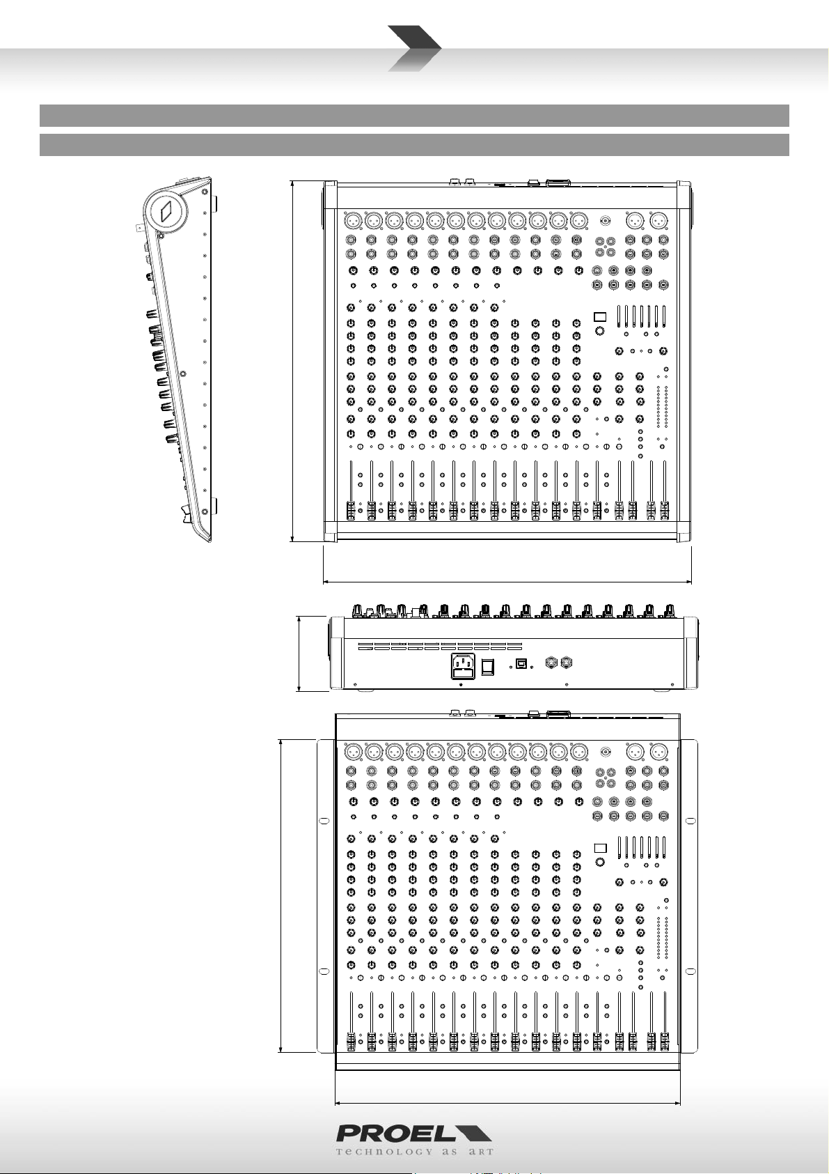
MECHANICAL DIMENSIONS
DIMENSIONI MECCANICHE
MECHANISCHE ABMESSUNGEN
DIMENSIONS MÉCANIQUES
DIMENSIONES MECÁNICAS
18.2"
46.2 cm
ﺔﻳﻛﻳﻧﺎﻛﻳﻣﻟﺍ ﺩﺎﻌﺑﻷﺍ
9.1 cm
15.6"
39.7 cm
46.5 cm
18.3"
3.60"
(9U RACK)
43.7 cm
17.2"
8
LAYOUT
LAY-OUT
LAYOUT
LAY-OUT
LAY-OUT
ﻡﻳﻣﺻﺗﻟﺍ
9
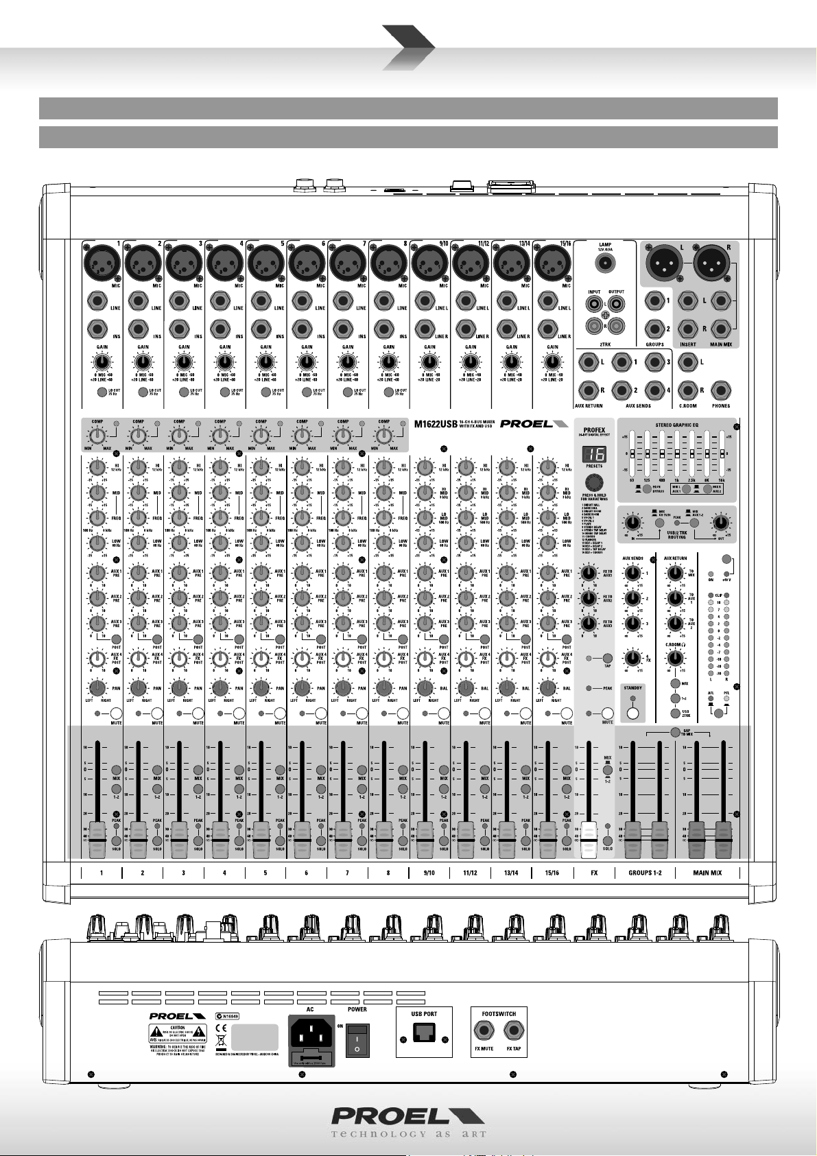
CONTROL PANEL (FIG.1)
PANNELLO DI CONTROLLO (FIG.1)
MISCHPULT (ABB.1)
PANNEAU DE COMMANDE (FIG.1)
1
2
3
4
23
24
25
26
5
6
7
8
7
27
PANEL DE CONTROL (FIG.1)
68
61 62 64
69
63
50
30
70
46
47
71
65
48
49
(1 ﻝﻛﺷﻟﺍ) ﻡﻛﺣﺗﻟﺍ ﺔﺣﻭﻟ
81
66
60
57 58 59
79
59
80
9
10
11
12
13
14
15
16
17
18
19
28
10
11
12
13
14
15
29
17
18
19
31
32
33
34
36
38
40
43
44
45
37
72
54
51
52
53
78
77
76
75
55
83
82
73
74
56
10
20
21
22
20
21
22
41
42
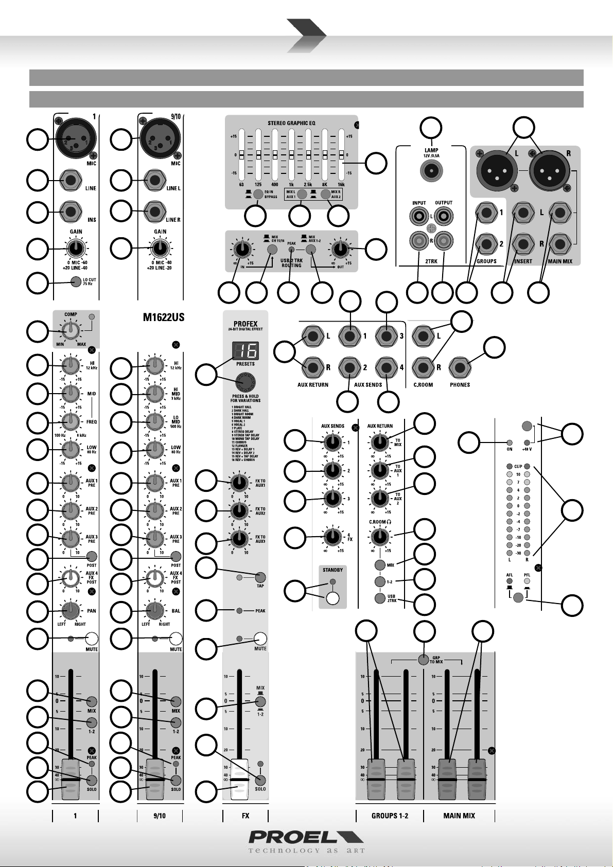
CONTROL PANEL (FIG.2)
PANNELLO DI CONTROLLO (FIG.2)
MISCHPULT (ABB.2)
PANNEAU DE COMMANDE (FIG.2)
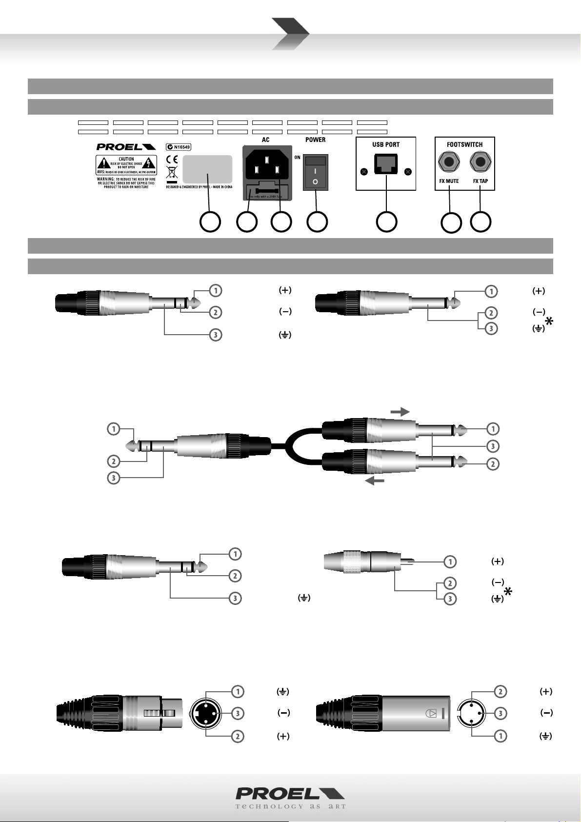
CONNECTIONS
CONNEXIONS
LINE IN, various OUT
LINE IN, various OUT
Jack (balanced)
LINE IN, OUT vari
Jack (balanced)
Jack (bilanciato)
verschiedene LINE IN und OUT
Klinkenstecker (symmetrisch)
LINE IN, OUT divers
Jack (symétrique)
LINE IN, OUT varios
Jack (balanceado)
PANEL DE CONTROL (FIG.2)
87
86
CONEXIONES
Ɵp - hot
ring - cold
sleeve - ground
ﺓﺩﺩﻌﺗﻣ ﺝﻭﺭﺧ ﻁﺧ ،ﻝﻭﺧﺩ ﻁﺧ
LINE IN, OUT vari
(ﻥﺯﺍﻭﺗﻣ) ﺕﻭﺻ ﻝّﺻﻭﻣ
Jack (bilanciato)
(2 ﻝﻛﺷﻟﺍ) ﻡﻛﺣﺗﻟﺍ ﺔﺣﻭﻟ
8485 35
67
ANSCHLÜSSECONNESSIONI
ﺕﻼﻳﺻﻭﺗﻟﺍ
LINE IN, various OUT
LINE IN, various OUT
Jack (unbalanced)
*note: connect both cold and ground to
Jack (unbalanced)
make cable from balanced to unbalanced
*note: connect both cold and ground
LINE IN, OUT vari
to make cable from balanced to unbalanced
Jack (sbilanciato)
*nota: conne ere insieme cold e ground
per cavi da bilanciato a sbilanciato
verschiedene LINE IN und OUT
Klinkenstecker (unsymmetrisch)
*hinweis: bei Verbindung von symmetrisch zu
unsymmetrisch Cold und Masse zusammen anschließen
LINE IN, OUT divers
Jack (asymétrique)
*note : brancher ensemble cold et ground
pour câbles de symétrique à asymétrique
SEND
39
Ɵp - hot
cold
ground
LINE IN, OUT vari
Jack (sbilanciato)
*nota: conneƩere insieme cold e ground
per cavi da bilanciato a sbilanciato
LINE IN, OUT varios
Jack (desbalanceado)
*nota: conecte juntos cold y ground para
cables de balanceado a desbalanceado
ﺓﺩﺩﻌﺗﻣ ﺝﻭﺭﺧ ﻁﺧ ،ﻝﻭﺧﺩ ﻁﺧ
(ﻥﺯﺍﻭﺗﻣﺭﻳﻏ) ﺕﻭﺻﻠّﺻﻭﻣ
ً
ﺎﻌﻣ ﻲﺿﺭﻷﺍ ﻭ ﺩﺭﺎﺑﻟﺍ ﻁﺑﺭﺍ :*!ﻪﺑﺗﻧﺍ
ﻥﺯﺍﻭﺗﻣﻟﺍ ﺭﻳﻏ ﻰﺗﺣﻭ ﻥﺯﺍﻭﺗﻣﻟﺍ ﻥﻣ ﺔﻳﺍﺩﺑ ﺕﻼﺑﺎﻛﻠﻟ
Ɵp - send
ring - return
sleeve - ground
INSERT
INSERT
Stereo Jack
Jack stereo
INSERT
Jack stereo
PHONES
PHONES
Stereo Jack
PHONES
Stereo Jack
Jack stereo
DE
DE
INSERT
Jack stéréo
PHONES
Stereo-Klinkenstecker
PHONES
Jack stéréo
INSERT
Jack estéreo
ﻝﺧﺩﺍ
ﻭﻳﺭﻳﺗﺳ ﺕﻭﺻ ﻝّﺻﻭﻣ
PHONES
Jack estéreo
ﻑﺗﺍﻭﻫ
ﻭﻳﺭﻳﺗﺳ ﺕﻭﺻ ﻝّﺻﻭﻣ
INSERT
Stereo Jack
PHONES
Jack stereo
Ɵp - leŌ
ring - right
sleeve - ground
ground
(2x) Mono Jack
(2x) Jack mono (2x) Mono Jack
(2x) Jack Mono
2TRK IN, OUT
Jack (unbalanced)
*note: connect both cold e ground to
make cable from balanced to unbalanced
2TRK IN, OUT
Jack (sbilanciato)
*nota: conne ere insieme cold e ground
per cavi da bilanciato a sbilanciato
2TRK IN, OUT
Jack (unbalanced)
*note: connect both cold and ground to
make cable from balanced to unbalanced
RETURN
DE
(2x) Mono Jack
(2x) Mono Jack
ﻱﺩﺭﻓ ﺕﻭﺻ ﻝّﺻﻭﻣ (2x)
hot
cold
ground
2TRK IN, OUT
Klinkenstecker (unsymmetrisch)
*hinweis: bei Verbindung von symmetrisch zu
unsymmetrisch Cold und Masse zusammen anschließen
2TRK IN, OUT
Jack (asymétrique)
*note : brancher ensemble cold et ground
pour câbles de symétrique à asymétrique
2TRK IN, OUT
Jack (sbilanciato)
*nota: conneƩere insieme cold e ground
per cavi da bilanciato a sbilanciato
2TRK IN, OUT
Jack (desbalanceado)
*nota: conecte juntos cold y ground para
cables de balanceado a desbalanceado
ﺝﺭﺧﻣ ،ﻝﺧﺩﻣ TRK 2
(ﻥﺯﺍﻭﺗﻣﺭﻳﻏ) ﺕﻭﺻﻠّﺻﻭﻣ
ً
ﺎﻌﻣ ﻲﺿﺭﻷﺍ ﻭ ﺩﺭﺎﺑﻟﺍ ﻁﺑﺭﺍ :*!ﻪﺑﺗﻧﺍ
ﻥﺯﺍﻭﺗﻣﻟﺍ ﺭﻳﻏ ﻰﺗﺣﻭ ﻥﺯﺍﻭﺗﻣﻟﺍ ﻥﻣ ﺔﻳﺍﺩﺑ ﺕﻼﺑﺎﻛﻠﻟ
Ɵp - send
sleeve - ground
Ɵp - return
hot
MAIN MIX OUT
Balanced female XLR
MAIN MIX OUT
MAIN MIX OUT
XLR bilanciato femmina
Balanced female XLR
MAIN MIX OUT
XLR symmetrisch, weiblich
MAIN MIX OUT
XLR symétrique femelle
MAIN MIX OUT
XLR balanceado hembra
ﻲﺳﻳﺋﺭﻟﺍ ﻲﺟﺭﺎﺧﻟﺍ ﺝﺯﻣﻟﺍ
ﻰﺛﻧﺃ ﻥﺯﺍﻭﺗﻣ XLR
MAIN MIX OUT
XLR bilanciato femmina
cold
hot
MIC INPUT
Balanced male XLR
MIC INPUT
MIC INPUT
XLR bilanciato maschio
Balanced male XLR
MIC INPUT
XLR symmetrisch, männlich
MIC INPUT
XLR symétrique mâle
MIC INPUT
XLR balanceado macho
MIC INPUT
ﻝﺎﺧﺩﺇ ﻥﻭﻓﻭﺭﻛﻳﻣ
ﺭﻛﺫ ﻥﺯﺍﻭﺗﻣ XLR
XLR bilanciato maschio
cold
ground
11
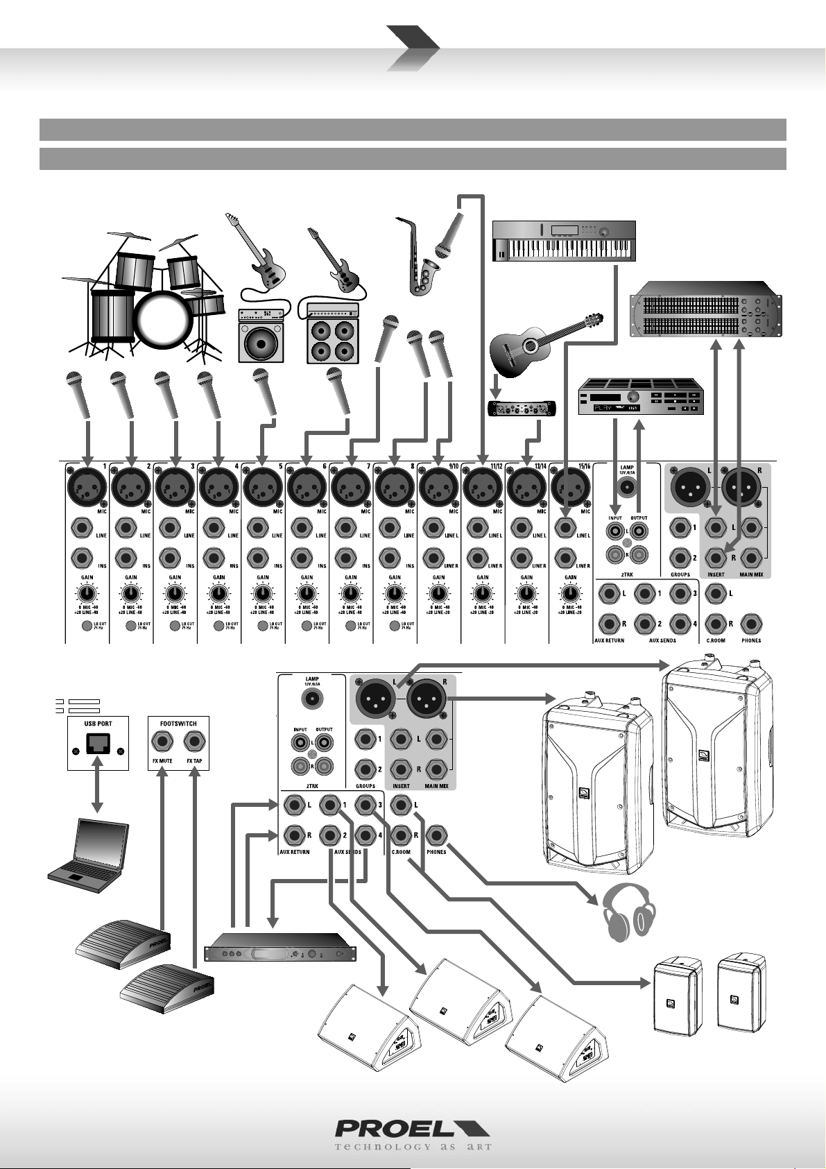
CONFIGURATION EXAMPLE
ESEMPIO DI CONFIGURAZIONE
KONFIGURATIONSBEISPIEL
EXEMPLE DE CONFIGURATION
DRUM KIT
ELECTRIC BASS
EJEMPLO DE CONFIGURACION
SAX MIC
ELECTRIC GUITAR
VOCAL MIC
CHOIR MICS
ﺔﺋﻳﻬﺗﻟﺍ ﻭﺃ ﻥﻳﻭﻛﺗﻟﺍ ﻥﻋ ﻝﺎﺛﻣ
KEYBOARD
DUAL 31 BAND EQUALIZER
ACOUSTIC
GUITAR
CD / MP3 / DVD RECORDER
AND PLAYER WITH AUDIO IN/OUT
DIBOX
PERSONAL COMPUTER
WITH USB 2.0 PORT
12
normally
open
temporary
pedals
(proel: GF29)
external sound processor
WD12A wedge monitor
or other stage monitors
FLASH12HDA
acƟve processed speaker
or other AUDIO SYSTEM
HEADPHONES
FLASH5A desktop monitors
or other AUDIO SYSTEM
ENGLISH LANGUAGE
SAFETY AND PRECAUTIONS
• CAUTION: before using this product read carefully the following safety instruc ons. Take a look of this manual en rely and preserve it for
future reference.
When using any electric product, basic precau ons should always be taken, including the following:
– To reduce the risk, close supervision is necessary when the product is used near children.
– Protect the apparatus from atmospheric agents and keep it away from water, rain and high humidity places.
– This product should be site away from heat sources such as radiators, lamps and any other device that generate heat.
– Care should be taken so that objects and liquids do not go inside the product.
– The product should be connected to a power supply mains line only of the type described on the opera ng instruc ons or as marked on the
product. Connect the apparatus to a power supply using only power cord included making always sure it is in good condi ons.
–
WARNING: The mains plug is used as disconnect device, the disconnect device shall remain readily operable.
– Power supply cord should be unplugged from the outlet during strong thunderstorm or when le unused for a long period of me.
– Do not place objects on the product’s power cord or place it in a posi on where anyone could trip over, walk on or roll anything over it. Do not
allow the product to rest on or to be installed over power cords of any type. Improper installa ons of this type create the possibility of fi re hazard
and/or personal injury.
IN CASE OF FAULT
• In case of fault or maintenance this product should be inspected only by qualifi ed service personnel when:
– There is a fl aw either in the connec ons or in the supplied connec ng cables.
– Liquids have spilled inside the product.
– The product has fallen and been damaged.
– The product does not appear to operate normally or exhibits a marked change in performance.
– The product has been lost liquids or gases or the enclosure is damaged.
• Do not operate on the product, it has no user-serviceable parts inside, refer servicing to an authorized maintenance centre.
CE CONFORMITY
• Proel products comply with direc ve 2004/108/EC (EMC), as stated in EN 55013 standard and with direc ve 2006/95/CE (LVD), as stated in EN
60065 standard.
• Under the EM disturbance, the ra o of signal-noise will be changed above 10dB.
PACKAGING, SHIPPING AND COMPLAINT
• This unit package has been submi ed to ISTA 1A integrity tests. We suggest you control the unit condi ons immediately a er unpacking it.
• If any damage is found, immediately advise the dealer. Keep all unit packaging parts to allow inspec on.
• Proel is not responsible for any damage that occurs during shipment.
• Products are sold “delivered ex warehouse” and shipment is at charge and risk of the buyer.
• Possible damages to unit should be immediately no fi ed to forwarder. Each complaint for package tampered with should be done within eight
days from product receipt.
WARRANTY AND PRODUCTS RETURN
• Proel products have opera ng warranty and comply their specifi ca ons, as stated by manufacturer.
• Proel warrants all materials, workmanship and proper opera on of this product for a period of two years from the original date of purchase. If
any defects are found in the materials or workmanship or if the product fails to func on properly during the applicable warranty period, the owner
should inform about these defects the dealer or the distributor, providing receipt or invoice of date of purchase and defect detailed descrip on.
This warranty does not extend to damage resul ng from improper installa on, misuse, neglect or abuse. Proel S.p.A. will verify damage on returned
units, and when the unit has been properly used and warranty is s ll valid, then the unit will be replaced or repaired. Proel S.p.A. is not responsible
for any "direct damage" or "indirect damage" caused by product defec veness.
INSTALLATION AND DISCLAIMER
• Proel products have been expressly designed for audio applica on, with signals in audio range (20Hz to 20kHz). Proel has no liability for damages
caused in case of lack of maintenance, modifi ca ons, improper use or improper installa on non-applying safety instruc ons.
• Proel S.p.A. reserves the right to change these specifi ca ons at any me without no ce.
• Proel S.p.A. declines any liability for damages to objects or persons caused by lacks of maintenance, improper use, installa on not performed
with safety precau ons and at the state of the art.
POWER SUPPLY AND MAINTENANCE
• Clean only with dry cloth.
• Before connec ng the product to the mains outlet make certain that the mains line voltage matches that shown on the rear of the product, a
tolerance of up to ±10% is acceptable.
• CHECK THE CONDITION OF THE PROTECTION FUSE, ACCESSIBLE OUTWARD, ONLY WITH THE APPARATUS SWITCHED OFF AND
DISCONNECTED FROM THE MAINS LINE OUTLET.
• REPLACE THE PROTECTION FUSE ONLY WITH SAME TYPE AS SHOWN ON THE PRODUCT.
• IF AFTER THE SUBSTITUTION, THE FUSE INTERRUPTS AGAIN THE APPARATUS WORKING, DO NOT TRY AGAIN THEN CONTACT
THE PROEL SERVICE CENTER.
13

GENERAL INFORMATION
Thank you for having chosen a PROEL product.
The new models in the M Series have been updated with new and improved features, repacked into a new stylish
package. While keeping the superior audio quality, the full set of features and the highest number of MIC inputs in the
category that have been the hallmarks of the previous M Series, the M models feature the new PROEL 24bit PROFEX
DSP, one of the fi nest digital eff ect of its class, providing 256 studio-grade algorithms (including mono and stereo TAP
DELAY) and a convenient 2 digit LED display.
Designed and engineered in Italy by PROEL, M mixers are hosted in an ultra-rugged stylish metal case with ABS sides,
providing extended durability for a stage-proof use. As in the previous series, all the models include both a padded
carrying bag and metal brackets for 19” rack moun ng.
M1622USB, off ering 16 inputs and 12 microphone channels, has been fi ed not only with one more AUX send and
with the USB rou ng, but also with an easy-to-use COMPRESSOR sec on on each MONO channel.
OPERATING INSTRUCTIONS (FIG. 1 / 2)
1. MIC Input
This is a female XLR connector, which accepts a balanced microphone input from almost any type of microphone. The
XLR inputs are wire as follows:
Pin 1 = shield or ground
Pin 2 = + posi ve or “hot”
Pin 3 = - nega ve or “cold”
2. LINE Input
This is a ¼” (6.3mm) jack connector, which accepts a balanced or unbalanced line level input signal from almost any
source. When connec ng a balanced signal, wire them as follows:
Tip = + posi ve or “hot”
Ring = - nega ve or “cold”
Sleeve = shield or ground
When connec ng an unbalanced signal, wire them as follows:
Tip = + posi ve or “hot”
Sleeve = shield or ground
3. INSERT Input-output
This is where you connect serial eff ects such as compressors, equalizers, de-essers or fi lters. The send is low-impedance
(150 ohms), capable of driving any line-level device. The return is high-impedance (10k ohms) and can be driven by
almost any device. Specialty “Y” cables, developed just for these jacks, are widely available on shops. Proel suggested
type is DHT540 (1.8 mt - 5.9 ). See also connec on chapter on this manual.
4. MONO CHANNEL GAIN Control
The gain control adjusts the input sensi vity of the mic and line inputs. This allows the signal from mics and instruments
to be adjusted to op mal internal levels. If the signals are plugged into the XLR input there is a 0 dB of gain with the
knob turned all way down, rising up to 60 dB of gain fully up. When connected to the jack input of any channels, there
is 20 dB of a enua on all way down and 40 dB of gain fully up, with a unity gain (0 dB) if centered.
5. LO CUT switch
This switch cuts bass frequencies below 75 Hz at a rate of 18 dB per octave. We recommend that you use the LO CUT
fi lter on every microphone applica on except kick drum, bass guitar, bassy synth patches, or recordings. These aside,
there isn’t much down there that you want to hear, and fi ltering it out makes the low stuff you do want much more
crisp and tasty. Not only that, but the LO CUT fi lter can help reduce the possibility of feedback in live situa ons and
it helps to conserve the amplifi er power. Another way to use the LO CUT fi lter is in combina on with the LOW EQ on
vocals during live performances. Many mes, bass shelving EQ can really benefi t voices. Trouble is, adding LOW EQ also
boosts stage rumble, mic handling clunks, and breath pops. LO CUT removes all those problems so you can add LOW
EQ without losing a woofer.
6. COMP compressor control and LED
Each mono channel features a single-control compressor, able to adjust the overall dynamic range of the signal and to
increase its loudness. When rota ng the control to the right, the loudest signals are reduced in order to avoid clipping,
while the quietest parts are boosted, producing a smooth, unifi ed sound with no excessive peaks or distor on.
The adjacent LED lights when the eff ect is engaged.
NOTE: Avoid se ng the compression too high, as the higher average output level that results may lead to feedback.
14

7. EQ sec on HIGH control
This control gives you up to 15dB boost or cut at 12KHz with a “SHELVING” curve shape. Use it to increase or reduce
the sound “clarity” or “brightness”.
8. EQ sec on MID control
This control gives you up to 15 dB boost or cut at the frequency determined by the FREQ knob (see FREQ next) with a
"PEAKING" curve shape. Use it to add or reduce the sound "presence".
9. EQ sec on FREQ control
This knob ranges from 100 Hz to 8 kHz and determines the center frequency for the MID EQ. This allows you to zero in
on the precise narrow band of frequencies you want to have aff ected by the MID EQ.
10. EQ sec on LOW control
This control gives you up to 15dB boost or cut at 80Hz with a “SHELVING” curve shape. Use it to increase or reduce the
sound “punch”.
11. AUX 1 control (pre)
This control sends the channel signal to the AUX 1 output. This signal is always pre-fader, i.e. it is independent by the
posi on of the FADER LEVEL control.
12. AUX 2 control (pre)
This control sends the channel signal to the AUX 2 output. This signal is always pre-fader, i.e. it is independent by the
posi on of the FADER LEVEL control.
13. AUX 3 control (pre/post)
This control sends the signal to the AUX 3 output. This signal is normally pre-fader, but it could be set post-fader pressing
the POST switch: in this case the signal level depends on the posi on of the channel FADER.
14. POST switch
Push this switch to set the AUX 3 control post-fader or release it to set the AUX 3 pre-fader. The pre-fader se ng is
preferable if you want to use the AUX 3 send as stage monitor, in order to have your stage mix independent from MAIN
MIX.
15. AUX 4 FX control (send to FX post)
This control sends the signal to the AUX 4 output and to the internal DIGITAL EFFECT PROCESSOR. This signal is postfader, in other words it depends on the posi on of the channel FADER.
16. PAN control
It adjusts the amount of channel signal sent to the le versus the right outputs. Use it to posi on the sound origin in a
panoramic stereo scene.
17. MUTE switch
When you engage a channel’s mute switch, its signal disappears from these outputs: MAIN MIX, GROUPS 1-2, AUX 1,
AUX 2, AUX 3, AUX4/FX.
NOTE: the input channel signal is not completely muted by this switch, so you can listen to it thru headphones and
C.ROOM outputs ac ng on the SOLO bu on in PFL mode only (see SOLO MODE).
18. MIX switch
Engaging this switch you assign the channel signal to the MAIN MIX bus regulated by the MAIN MIX faders. Typically,
the MIX switch will be engaged on all channels except those assigned separately to GROUPS 1-2.
19. 1-2 switch
Engaging this switch you assign the channel signal to the GROUPS 1-2 bus regulated by the GROUPS 1-2 faders. You
can use the GROUPS 1-2 jacks as separate outputs or, engaging the switch GRP TO MIX, to create a submix for a set of
channels (all the drums channels, for instance): in this case you can control the assigned GROUPS 1-2 signals together
and independently from the rest of the mix.
20. PEAK detector and SOLO ac ve
This LED has two func ons:
If the PEAK LED lights permanently this means that you have ac vated the SOLO switch of this channel.
If the PEAK LED fl ashes this means that the input signal is near to the CLIPPING point.
IMPORTANT: if the LED PEAK fl ashes reduce the level of the input signal using the GAIN control.
21. SOLO switch
This switch allows you to hear signals through your headphones or control room outputs and to display the level on LED
meters. Use the SOLO in live sets to pre-listen channels before they are fed into the mix or just to check out a par cular
channel any me during a session. You can solo as many channels at a me as you like.
IMPORTANT: The solo signal is pre-fader if SOLO MODE is in PFL posi on, so what you check is the signal entering the
15

channel. The solo signal is post-fader if SOLO MODE is in AFL posi on, so what you check is the signal sent from the
channel fader to the MAIN MIX.
22. FADER LEVEL control
It adjusts the level of the channel signal and sends it to the MAIN MIX and/or to the GROUPS 1-2 buses.
23. MIC MONO Input
This is a female XLR connector, which accepts a balanced microphone input from almost any type of microphone. Wiring
is the same of previous paragraphs.
24. LINE L MONO Input
This is a ¼” (6.3mm) jack connector, which accepts a balanced or unbalanced line level input signal from almost any line
source. If the LINE R jack is not inserted, this channel operates like a MONO channel with this input as a single signal
source. Wiring is the same of previous paragraphs.
25. LINE R Input
This is a ¼” (6.3mm) jack connector, which accepts a balanced or unbalanced line level input signal from almost any line
source. This is used only in presence of LINE L jack input to use the channel as STEREO.
26. STEREO CHANNEL GAIN Control
The gain control adjusts the input sensi vity of the mic and line inputs. This allows the signal from mics and instruments
to be adjusted to op mal internal levels. If the signals are plugged into the XLR input there is a 0 dB of gain with the
knob turned all way down, rising up to 40 dB of gain fully up. When connected to the jack input of any channels, there
is 20 dB of a enua on all way down and 20 dB of gain fully up, with a unity gain (0 dB) if centered.
27. EQ sec on HI MID control
This control gives you up to 15 dB boost or cut at 3 KHz with a "PEAKING" curve shape. Use it to add or reduce the
sound "clarity".
28. EQ sec on LO MID control
This control gives you up to 15 dB boost or cut at 500 Hz with a "PEAKING" curve shape. Use it to add or reduce the
sound "presence".
29. BAL control
It adjusts the amount of channel signal sent to the le versus the right outputs if the channel is used as MONO, or it
fades the LEFT or RIGHT signal amount if the channel is used as STEREO.
30. PRESETS selector and display
The internal PROFEX digital eff ect processor is built around a powerful DSP and 24bit AD/DA converters. It includes 16
diff erent presets of studio-grade eff ect algorithm, each one featuring 16 diff erent varia ons of the internal parameters,
for a total of 256 eff ects available.
HOW TO USE THE PROFEX EFFECT:
- rotate the SELECTOR knob to choose the type of eff ect (preset) you want to use;
- to select a varia on of the preset, press and hold the knob un l the display fl ashes;
- rotate the knob and choose one of the 16 varia ons available;
- press and hold again the knob un l the display stops fl ashing to confi rm the selec on and to return back to the
preset selec on;
- send the signal to the eff ect with the AUX control (10) of the channel you want to add the eff ect to;
- rotate the FX LEVEL (25) knob un l you hear the eff ect added to the original signal;
- adjust the AUX controls (10) just before the signal input clipping indicated by the peak led (22);
- re-adjust the FX LEVEL (25) knob to combine the wet eff ected signal with the natural dry signal.
NOTE: the preset and the varia on selected in the PROFEX eff ect are kept in the memory even if you turn off the
mixer.
PRESET DESCRIPTION:
p 1. BRIGHT HALL - This type of reverb simulates the ambience of a grand concert hall. Dense, smooth reverb with
long pre delay and a lot of high frequency refl ec ons. Works well with vocals, electric and acous c guitars, strings.
The VARIATIONS vary the decay me and the hall size from bigger [1] to smallest [16].
p 2. DARK HALL - This type of reverb simulates the ambience of a grand concert hall. Dense, smooth reverb with long
pre delay and a few of high frequency refl ec ons. Works well with vocals, guitars, woodwinds.
The VARIATIONS vary the decay me and the hall size from bigger [1] to smallest [16].
p 3. BRIGHT ROOM - This type of reverb reproduces the more in mate ambience of natural room acous cs. Feature
a lot of early refl ec ons with a lot of high frequency. Works well with vocals, woodwinds, strings, drums.
The VARIATIONS vary the decay me and the room size from bigger [1] to smallest [16].
16

p 4. DARK ROOM - This type of reverb reproduces the more in mate ambience of natural room acous cs. Feature a
lot lot of early refl ec ons with a few of high frequency. Works well with vocals, fi ngered guitars, drums.
The VARIATIONS vary the decay me and the room size from bigger [1] to smallest [16].
p 5. VOCAL 1 (STAGE REVERB) - Amazing reverb designed for vocals with a long tail.
The VARIATIONS vary the decay me from long tail [1] to short tail [16], alterna ng plate, spring or hall types of
reverb.
p 6. VOCAL 2 (CLUB REVERB) - Amazing reverb designed for vocals with a dense tail.
The VARIATIONS vary the decay me from long tail [1] to short tail [16], alterna ng tape, hall or spring types of
reverb.
p 7. PLATE - This is a simula on of metal plate reverb, as used on classic recordings from the ‘70s and ‘80s.
The VARIATIONS vary the decay me from long tail [1] to short tail [16].
p 8. STEREO DELAY - Echo eff ect with ping-pong of le and right channels.
The VARIATIONS vary from long delay mes [1] to short delay mes [16].
p 9. STEREO TAP DELAY - Like STEREO DELAY above with me set by the user TAP bu on (22) just below.
The VARIATIONS vary from 5% [1] to 90% [16] of feedback quan ty.
p 10. MONO TAP DELAY - Typical mono delay with me set by the user TAP bu on (22) just below.
The VARIATIONS vary from 0% [1] to 75% [16] of feedback quan ty.
p 11. CHORUS - Typical modula on eff ect, provides a so , ethereal sweeping eff ect. Perfect for enhancement of
electric and acous c guitar and bass. Also adds a drama c eff ect to vocals, par cularly group harmonies and choirs.
The VARIATIONS increase the modula on frequency from 0.5Hz [1] to 5Hz [16].
p 12. FLANGER - Typical modula on eff ect, creates a strong sweeping eff ect, par cularly eff ec
guitar, lead and rhythm.
The VARIATIONS increases the modula on frequency from 0.2Hz [1] to 3Hz [16].
p 13. REVERB+DELAY 1 - Typical vocal hall reverb and stereo delay combined together.
The VARIATIONS vary from long tail [1] to short tail [16].
p 14. REVERB+DELAY 2 - Typical vocal hall reverb and mono delay combined together.
The VARIATIONS vary from long tail [1] to short tail [16].
p 15. REVERB+TAP DELAY - Typical vocal hall reverb and mono TAP delay combined together.
The mono delay me is set by the user TAP bu on (22) just below.
The VARIATIONS vary from long tail [1] to short tail [16] and from 0% to 75% of feedback quan ty [1-16].
p 16. REV+CHORUS - Typical vocal reverb and chorus eff ect combined together.
The VARIATIONS vary from long tail [1] to short tail [16] and increases the modula on frequency from 0.5Hz to 5Hz
[1-16].
31. FX TO AUX1 level control
It adjusts the level of the internal eff ect signal sent to the AUX 1 output.
32. FX TO AUX2 level control
It adjusts the level of the internal eff ect signal sent to the AUX 2 output.
33. FX TO AUX3 level control
It adjusts the level of the internal eff ect signal sent to the AUX 3 output.
34. TAP bu on and LED
When “TAP DELAY” eff ects (p 9, 10, 15) are selected, by pushing at least two mes this bu on it’s possible to set the
desired delay me, according to music rhythm. The TAP LED fl ashes in sync with the delay me set.
35. FX TAP jack input
¼” (6.3mm) unbalanced (TS) jack for temporary, normally open footswitch (not supplied - suggested footswitch is the
PROEL model GF29). When “TAP DELAY” eff ects (p 9, 10, 15) are selected, by pressing at least two mes the footswitch
it’s possible to set the desired delay me, according to music rhythm.
36. PEAK detector
If the peak LED fl ashes this means that the signal is too high, near to the clipping of the eff ect input stage. In this case,
reduce the level of the AUX4 / FX channel sends (15) or AUX SEND 4 FX master send (37).
37. AUX SEND 4 FX LEVEL control
It adjusts the master level of AUX4 jack output and also the signal sent to internal eff ect. Use it to reduce the level of
signal sent to the internal eff ect if the PEAK LED is fl ashing. This control ranges from off through unity (the center detent
posi on) on up to 15 dB of extra gain (fully clockwise).
38. MUTE bu on
Engage this switch if you want to mute the signal from the internal eff ect.
NOTE: the eff ect can be turned on/off also by means of a footswitch connected to the FX MUTE jack socket.
ve on rock electric
17

39. FX MUTE jack input
You can connect a footswitch to MUTE the mixer internal eff ect (suggested footswitch is PROEL model GF29).
40. MIX / 1-2 switch
This switch assigns the FX output signal to the MAIN MIX bus (if dis-engaged) or to the GROUP 1-2 bus (if engaged).
Typically, it is set to MIX if the internal eff ect is used only for channels assigned to MIX bus or to 1-2 if the internal eff ect
is used only for channels assigned to 1-2 bus.
41. FX SOLO switch and LED
This switch allows you to hear the signals of FX send (PFL) or FX return (AFL) through your headphones or control room
outputs and to display the level on LED meters.
42. FX LEVEL control
It adjusts the level of the internal eff ect signal sent to the MAIN MIX or GROUPS 1-2 outputs.
43. AUX 1 SEND LEVEL control
It adjusts the general level of the AUX 1 SEND output. This control ranges from off to +15 dB of gain when fully clockwise.
44. AUX 2 SEND LEVEL control
It adjusts the general level of the AUX 2 SEND output. This control ranges from off to +15 dB of gain when fully clockwise.
45. AUX 3 SEND LEVEL control
It adjusts the general level of the AUX 3 SEND output. This control ranges from off to +15 dB of gain when fully clockwise.
46. AUX SEND 1 jack output
This jack connector sends out unbalanced line-level signals made of the sum of the input channel’s AUX 1 sends, usually
for connec ng to the inputs of an external eff ect devices or stage monitor amplifi ers.
47. AUX SEND 2 jack output
This jack connector sends out unbalanced line-level signals made of the sum of the input channel’s AUX 2 sends, usually
for connec ng to the inputs of an external eff ect devices or stage monitor amplifi ers.
48. AUX SEND 3 jack output
This jack connector sends out unbalanced line-level signals made of the sum of the input channel’s AUX 3 sends, usually
for connec ng to the inputs of an external eff ect devices or stage monitor amplifi ers. This signal can be pre or post fader,
it depends how POST switch (14) of each channel is set, usually all bu ons are set as pre or post.
49. AUX SEND 4 jack output
This jack connector sends out unbalanced line-level signals made of the sum of the input channel’s AUX 4 sends, usually
for connec ng to the inputs of an external eff ect devices. This signal is post-fader, or in other words it depends on the
posi on of the channel’s FADER.
50. AUX RETURN jack input
Unbalanced jack connectors of the auxiliary stereo input (note: the L input can be used as MONO if R input is le
unconnected). This input can be used for the return signal from outboard eff ects or for connec ng any instrument or
equipment with a line output.
51. AUX RETURN TO MIX level control
It adjusts the level of the AUX RETURN inputs and send it to the MAIN MIX.
52. AUX RETURN TO AUX 1 level control
It adjusts the level of the AUX RETURN inputs and send it to the AUX 1 output.
53. AUX RETURN TO AUX 2 level control
It adjusts the level of the AUX RETURN inputs and send it to the AUX 2 output.
54. GROUPS 1-2 FADER control
The GROUP 1-2 FADERS control the level of the GROUP 1-2 bus to its outputs or, if "GRP TO MIX" switch is down, to the
MAIN MIX bus.
55. GRP TO MIX switch
This switch assigns the GROUP 1-2 bus to the MAIN MIX bus. As explained earlier, pushing down this switch you can use
the GROUP 1-2 as sub-mix groups, enabling you to control the level of several channels with one knob.
56. MAIN MIX FADER level control
The MAIN MIX FADER controls the output level just before the MAIN MIX outputs. When the fader is fully down the
MAIN MIX is off , the “0” marking indicates a +4 dBu nominal output level. Typically this fader is set near the “0” label
and le alone, but it can be used for song fadeouts or quick system-wide mutes.
NOTE: the MAIN OUT is a true balanced output that can send the signal on a balanced line with or without a phantom
power ac ve. So the M1622USB mixer can also be used as a combina on mixer + DI box for sending the signals to a
18

bigger main mixer console.
57. GROUPS 1-2 jack output
These JACK connectors provide an unbalanced line-level signal from the GROUPS 1-2 stereo bus signal overall controlled
by the GROUPS 1-2 FADER level control.
58. MAIN MIX INSERT Input output
This is where you connect serial eff ects before the MAIN MIX FADER control. These serial eff ects usually are compressors
or equalizers. The send is low-impedance (150 ohms), capable of driving any line-level device. The return is highimpedance (10k ohms) and can be driven by almost any device. Specialty “Y” cables, designed just for this applica on,
are widely available on shops. Specialty “Y” cables, developed just for these jacks, are widely available on shops. Proel
suggested type is DHT540 (1.8 mt - 5.9 ). See also connec on chapter on this manual.
59. MAIN MIX L & R xlr and jack output (balanced)
These XLR and jack connectors provide a balanced line-level signal that represents the fully mixed stereo signal
controlled by the MAIN MIX fader. Connect these to the inputs of your power amplifi er, powered speaker or processors
(equalizers, mul -band compressors and so on).
60. 2TRK inputs
Use these unbalanced RCA connectors to patch the output of a player, such as an analog tape deck, MP3 player, CD/DVD
player or a Personal Computer.
61. USB/2TRK IN level control
It adjusts the level of the 2TRK INPUT and USB input (audio signal from PC).
62. MIX - CH15/16 switch
This switch routes the 2TRK IN or USB input signal directly to MAIN MIX outputs or to the channel 15/16. Rou ng the
signal to channel 15/16, you can use all features of the stereo channel before sending the signal to the MAIN MIX:
equaliza on, aux sends and the internal eff ect processor.
63. 2 TRK OUT PEAK detector
If the peak LED fl ashes mean that the signal is too high, near to the clipping the output stage. In this case, reduce the
level of the USB/2TRK OUT level control.
64. MIX - AUX 1-2 switch
This switch selects which signal is sent to the 2TRK OUT and to the USB port. Choosing the MAIN MIX signal you can
record a whole mix session such as a live performance. Choosing AUX 1-2 you can record ll two diff erent instruments
in two diff erent tracks of your DAW recording so ware, rou ng them thru AUX 1 and AUX 2 respec vely and using the
MAIN MIX for monitoring.
65. USB/2TRK OUT level control
It adjust the level of signal sent to the 2TRK OUTPUT and to the USB port. This control is a er the MAIN MIX fader
control.
66. 2TRK outputs
Use these unbalanced RCA connectors to send out the MAIN MIX or AUX 1/2 signals to a recorder, such as an analog
tape or an A/D converter connected to a Personal Computer.
67. USB PORT socket
It routes the 2TRK OUT and the 2TRK IN through the USB port in crystal-clean, 16-bit, 44.1 kHz stereo digital audio. Use
the M1622USB as a high-quality soundcard for recording and playback with Windows and Macintosh computers.
VERY IMPORTANT INFORMATIONS:
- The M1622USB internal USB soundcard needs a personal computer with a USB 2.0 port and a Windows (XP or later)
or Mac OSX (10.3 or later) Opera ng Systems.
- The internal USB soundcard DOESN'T REQUIRE A DEDICATE SOFTWARE DRIVER to work with Windows or Mac OSX.
- For in/out signal rou ng inside the computer and the DAW so ware refer to the documenta on included with the
computer and DAW so ware.
- Tipically, a er you have connected the USB cable and powered on the mixer, the M1622USB soundcard is visible from
the computer and DAW so ware as: "USB Audio CODEC" (or with a similar name, depending on the OS version).
68. EQ IN / BYPASS switch
Engaging this switch you bypass the 7-band STEREO graphic equalizer, whether is used on MIX outputs or on AUX
sends.
69. MIX L / AUX 1 switch
This bu on assigns the LEFT channel of the 7-band STEREO graphic equalizer to MIX LEFT (switch released) or to AUX
1 send (bu on pressed). Use the equalizer on the MIX outputs to correct the response of your main speaker system or
19

use it on the AUX's sends to avoid feedbacks on stage monitors.
IMPORTANT: press always both MIX L / AUX1 and MIX R / AUX2 switches to assign both the equalizers channels at the
same me to MIX outputs LEFT & RIGHT or to AUX's sends 1 & 2.
70. MIX R / AUX 2 switch
This bu on assigns the RIGHT channel of the 7-band STEREO graphic equalizer to MIX RIGHT (switch released) or to
AUX2 send (bu on pressed). Use it ALWAYS together with MIX L / AUX 2 bu on.
71. STEREO GRAPHIC EQ slider
These sliders gives you up to 15 dB boost or cut at 63 Hz, 125 Hz, 400 Hz, 1 KHz, 2.5 KHz, 8 KHz and 16 KHz.
72. STAND-BY switch
Engage the STAND-BY switch and instantly the en re MAIN MIX is switched off . You can use this switch as a MASTER
MUTE while you are wai ng for the gig to start. Since the 2TRK IN input it's s ll assigned to the MAIN MIX when the
STAND-BY bu on is pressed, you can also play some music during the intermission. When it's me to start the gig, just
release the bu on and all musicians will be ready to play.
73. L & R LEVEL METERS
The level meters are made of two columns of of twelve LEDs with three colours to indicate diff erent ranges of signal
level:
• green = shows the normal opera ve level of the signal (from -30 to +4 dBu)
• yellow = shows the nominal opera ve level of the signal (from +7 to +10 dBu)
• red = shows a high signal level (near +20 dBu CLIP level).
If the SOLO switch is dis-engaged, the meters display what is selected by (75) (76) and (77) switches, choosing between
MAIN MIX (post fader), GROUP 1-2 (post fader) or 2TRK IN.
If one or more SOLO switches are engaged, the meters display the solo informa on. If the SOLO MODE is set as PFL
(pre fader level) the meters show only a mono signal on both column, if it is set as AFL (a er fader level) they show the
stereo signal a er the channel FADER and PAN controls.
NOTE: in order to obtain a proper visualiza on, we recommend to press only one switch at a me.
74. SOLO MODE switch
Allows to select if the listening and the visualiza on of the channels selected with the SOLO bu ons are PRE FADER
(PFL) or POST FADER (AFL).
- PFL: PRE-FADER LEVEL, the input signal, already controlled by the channel EQ, is shown on the LED METERS and sent
to the C.ROOM/PHONES outputs. The PFL mode has to be used for se ng the right level of the input signal (usually
around 0 dB) and to avoid input satura on and distor on.
- AFL: AFTER-FADER LEVEL, the input signal, already controlled by the channel EQ and by the channel fader, is shown on
the LED METERS and sent to the C.ROOM/PHONES outputs.
75. 2TRK to C.ROOM switch
Push this switch to send the 2TRK input signal and USB input signal to C.ROOM and PHONES outputs.
76. MIX to C.ROOM switch
Push this switch to send the MIX bus signal to C.ROOM and PHONES outputs.
77. 1-2 to C.ROOM switch
Push this switch to send the GROUP 1-2 bus signal to C.ROOM and PHONES outputs.
NOTE: for a correct opera on we suggest to choose these three switches (75) or (76) or (77) one a me.
IMPORTANT: these switches also select which signal is displayed on LED METERS when none channel is soloed.
78. C.ROOM/PHONES LEVEL control
This controls the CONTROL ROOM and PHONES output’s level.
NOTE: The signal at these outputs is the same.
79. C.ROOM jack outputs
These JACK connectors provide an unbalanced line-level signal that can be used to monitor the MAIN MIX / GRP 1-2 /
USB 2TRK IN program or what is soloed.
80. PHONES stereo jack output
STEREO JACK connector for the headphones output: only stereo headphones with a minimum impedance of 32 Ohms
should be connected to this output.
81. LAMP 12V / 0.5A socket
This BNC connector provides +12V power supply for gooseneck lamps. Use only lamps with MAX 5W power consump on.
PROEL suggested types are SDC670 or SDC670LED.
20

82. +48V phantom switch and LED
This switch ac vates (LED on) and deac vates (LED off ) the phantom power on MIC Inputs. Most professional condenser
microphones require phantom power, which is a lower DC voltage delivered to the microphone on pin 2 and 3 of the
XLR microphone connector. Dynamic microphones do not require phantom power, however phantom power will not
harm most dynamic microphones should you plug one in while the phantom power is on. Check the manual of your
microphone to fi nd out for sure whether or not phantom power can damage it.
83. ON led
Indicates when the mixer is switched on.
84. POWER switch
Make sure that all master output knobs are turned all the way down when powering your mixer up or down.
85. AC~ socket
Here’s where you plug in your mixer’s mains supply cord. You should always use the mains cord supplied with the mixer.
Be sure your mixer is turned off before you plug the mains supply cord into an electrical outlet.
86. FUSE holder
Here is placed the mains protec on fuse. Please follow the instruc ons on page 10 of this manual to replace it.
87. PRODUCT LABEL
In this label are wri en the most important informa on about the mixer, model, line voltage, consump on, serial
number.
21

LINGUA ITALIANA
AVVERTENZE PER LA SICUREZZA
• ATTENZIONE: Durante le fasi di uso o manutenzione, devono essere prese alcune precauzioni onde evitare danneggiamen alle stru ure
meccaniche ed ele roniche del prodo o.
Prima di u lizzare il prodo o, si prega di leggere a entamente le seguen istruzioni per la sicurezza. Prendere visione del manuale d’uso e
conservarlo per successive consultazioni:
– In presenza di bambini, controllare che il prodo o non rappresen un pericolo.
– Posizionare l’apparecchio al riparo dagli agen atmosferici e a distanza di sicurezza dall’acqua, dalla pioggia e dai luoghi ad alto grado di umidità.
– Collocare o posizionare il prodo o lontano da fon di calore quali radiatori, griglie di riscaldamento e ogni altro disposi vo che produca calore.
– Evitare che qualsiasi ogge o o sostanza liquida entri all’interno del prodo o.
– Il prodo o deve essere connesso esclusivamente alla rete ele rica delle cara eris che descri e nel manuale d’uso o scri e sul prodo o, usando
esclusivamente il cavo rete in dotazione e controllando sempre che sia in buono stato, in par colare la spina e il punto in cui il cavo esce dal prodo o.
–
ATTENZIONE: Se il cavo rete viene scollegato dall'apparecchio per spegnerlo, il cavo rete rimarrà opera vo in quanto la sua spina è ancora
collegata alla rete ele rica.
– Disconne ere il prodo o dalla rete ele rica durante for temporali o se non viene usato per un lungo periodo di tempo.
– Non disporre ogge sul cavo di alimentazione, non disporre i cavi di alimentazione e segnale in modo che qualcuno possa incianparci. Altresì
non disporre l’apparecchio sui cavi di altri appara . Installazioni inappropriate di questo po possono creare la possibilità di rischio di incendio
e/o danni alle persone.
IN CASO DI GUASTO
• In caso di guasto o manutenzione questo prodo o deve essere ispezionato da personale qualifi cato quando:
– Ci sono dife sulle connessioni o sui cavi di collegamento in dotazione.
– Sostanze liquide sono penetrate all’interno del prodo o.
– Il prodo o è caduto e si è danneggiato.
– Il prodo o non funziona normalmente esibendo una marcato cambio di prestazioni.
– Il prodo o perde sostanze liquide o gassose o ha l’involucro danneggiato.
• Non intervenire sul prodo o. Rivolgersi a un centro di assistenza autorizzato Proel.
CONFORMITÀ CE
• I Prodo Proel sono conformi alla dire va 2004/108/EC (EMC), secondo lo standard EN 55013 ed alla dire va 2006/95/CE (LVD), secondo lo
standard EN 60065.
• Se so oposto a disturbi EM, il rapporto segnale-rumore può essere superiore a 10dB.
IMBALLAGGIO, TRASPORTO E RECLAMI
• L’imballo è stato so oposto a test di integrità secondo la procedura ISTA 1A. Si raccomanda di controllare il prodo o subito dopo l’apertura dell’imballo.
• Se vengono riscontra danni informare immediatamente il rivenditore. Conservare quindi l’imballo completo per perme erne l’ispezione.
• Proel declina ogni responsabilità per danni causa dal trasporto.
• Le merci sono vendute “franco nostra sede” e viaggiano sempre a rischio e pericolo del distributore.
• Eventuali avarie e danni dovranno essere contesta al ve ore. Ogni reclamo per imballi manomessi dovrà essere inoltrato entro 8 giorni dal ricevimento.
GARANZIE E RESI
• I Prodo Proel sono provvis della garanzia di funzionamento e di conformità alle proprie specifi che, come dichiarate dal costru ore.
• La garanzia di funzionamento è di 24 mesi dopo la data di acquisto. I dife rileva entro il periodo di garanzia sui prodo vendu , a ribuibili a materiali
dife osi o dife di costruzione, devono essere tempes vamente segnala al proprio rivenditore o distributore, allegando evidenza scri a della data
di acquisto e descrizione del po di dife o riscontrato. Sono esclusi dalla garanzia dife causa da uso improprio o manomissione. Proel SpA constata
tramite verifi ca sui resi la dife osità dichiarata, correlata all’appropriato u lizzo, e l’eff e va validità della garanzia; provvede quindi alla sos tuzione o
riparazione dei prodo , declinando tu avia ogni obbligo di risarcimento per danni dire o indire eventualmente derivan dalla dife osità.
INSTALLAZIONE E LIMITAZIONI D’USO
• I Prodo Proel sono des na esclusivamente ad un u lizzo specifi co di po sonoro: segnali di ingresso di po audio (20Hz-20kHz). Proel declina ogni
responsabilità per danni a terzi causa da mancata manutenzione, manomissioni, uso improprio o installazione non eseguita secondo le norme di sicurezza.
• La Proel S.p.a. si riserva di modifi care il prodo o e le sue specifi che senza preavviso.
• Proel declina ogni responsabilità per danni a terzi causa da mancata manutenzione, manomissioni, uso improprio o installazione non eseguita
secondo le norme di sicurezza e a regola d'arte.
ALIMENTAZIONE E MANUTENZIONE
• Pulire il prodo o unicamente con un panno asciu o.
• Prima di collegare l'apparecchio alla presa di corrente, accertatevi che la tensione di rete corrisponda a quella indicata sul retro dell’apparato, è
consen to un margine del ±10% rispe o al valore nominale.
• CONTROLLARE LO STATO DEL FUSIBILE DI PROTEZIONE ACCESSIBILE DALL'ESTERNO ESCLUSIVAMENTE AD APPARATO SPENTO E
DISCONNESSO DALLA RETE ELETTRICA.
• RIMPIAZZARE IL FUSIBILE DI PROTEZIONE ESCLUSIVAMENTE CON UN FUSIBILE CON LE MEDESIME CARATTERISTICHE RIPORTATE
SUL PRODOTTO.
• SE DOPO LA SOSTITUZIONE, IL FUSIBILE INTERROMPE NUOVAMENTE IL FUNZIONAMENTO DELL'APPARATO, NON INSISTERE E
CONTATTARE IL SERVIZIO ASSISTENZA PROEL.
22

INFORMAZIONI GENERALI
Grazie per aver scelto un prodo o PROEL.
I nuovi modelli della serie M sono sta aggiorna con nuove e migliori cara eris che e con un design innova vo e
originale. Oltre a mantenere i pun di forza della precedente serie M, tra cui la qualità audio superiore, un set completo
di funzioni e il maggiore numero di ingressi MIC della categoria, tu i nuovi modelli serie M dispongono del nuovo DSP
PROEL a 24bit PROFEX, uno dei migliori eff e digitali u lizza su mixer compa , che include 256 algoritmi di qualità
studio (inclusi TAP DELAY mono e stereo) ed un u le display LED a 2 digit.
Proge a ed ingegnerizza in Italia da PROEL, i mixer M sono alloggia in telai di metallo ultra-robus ed elegan
con fi anchi in ABS, in grado di garan re un uso prolungato a prova di palco. Tu i modelli includono sia una borsa da
trasporto imbo ta che ada atori per il montaggio in rack da 19”.
Il nuovo mixer M1622USB, dispone di 16 ingressi di cui 12 microfonici come il modello precedente, include una mandata AUX
in più e una fl essibile ges one del segnale USB del computer e dotato inoltre di un COMPRESSORE per ogni ingresso MONO.
ISTRUZIONI OPERATIVE (FIG. 1 / 2)
1. MIC (ingresso microfono)
È un conne ore femmina XLR, in grado di acce are un segnale microfonico bilanciato da ogni po di microfono.
L’ingresso XLR ha i seguen terminali:
Pin 1 = schermo o massa
Pin 2 = + posi vo o “caldo”
Pin 3 = - nega vo o “freddo”
2. LINE (ingresso linea)
È un conne ore femmina da ¼” (6.3mm) po jack, in grado di acce are un segnale a livello linea bilanciato o sbilanciato
da ogni po di sorgente. Quando si collega un segnale bilanciato, le terminazioni sono le seguen :
Tip (punta) = + posi vo o “caldo”
Ring (anello) = - nega vo o “freddo”
Sleeve (manico o) = schermo o massa
Quando si collega un segnale sbilanciato, le terminazioni sono le seguen :
Tip (punta) = + posi vo o “caldo”
Sleeve (manico o) = schermo o massa
3. INSERT (ingresso-uscita eff e o)
A questo conne ore possono essere collega eff e seriali quali compressori, equalizzatori, de-essers o fi ltri. La mandata
è a bassa impedenza (150 ohms), capace di pilotare ogni po di disposi vo con livello linea. Il ritorno è ad alta impedenza
(10k ohms) e può essere collegato ad ogni po di disposi vo con livello linea. Speciali cavi “Y”, realizza appositamente
per questa uscita jack, sono disponibili presso i negozi. Proel suggerisce il po DHT540 (1.8 mt - 5.9 ). Consultare anche
il capitolo delle connessioni in questo manuale.
4. GAIN (controllo guadagno)
Il controllo GAIN regola la sensibilità di ingresso dell’ingresso MIC o LINE. Questo perme e di regolare il segnale in
ingresso da microfoni o strumen al livello o male interno del mixer. Se il segnale è collegato all’ingresso XLR si hanno 0
dB di guadagno con la manopola girata al minimo e fi no a 60 dB girandola verso il massimo. Quando collegato all’ingresso
jack si hanno 20 dB di a enuazione con la manopola girata al minimo e 40 dB di guadagno se girata al massimo, con un
guadagno unitario (0 dB) se posta al centro.
5. LO CUT (fi ltro elimina bassi)
Questo tasto elimina le basse frequenze al di so o dei 75 Hz con 18 dB per o ava. L’uso del fi ltro LO CUT è consigliato
su ogni microfono ecce o la grancassa, il basso, sinte zzatori o tracce pre-registrate. Infa , tranne che per ques
strumen , per tu gli altri al di so o di tale frequenza in genere non c’è nulla da ascoltare, eliminandoli i bassi restan
al di sopra dei 75Hz saranno più incisivi e piacevoli. Non solo ma dal vivo, in abbinamento al EQ LOW e in par colare
sulle voci, l’uso del fi ltro LO CUT riduce la possibilità di rientri (feedback) e preserva la potenza dell’amplifi catore. LO CUT
elimina i rumori da maneggiamento dei microfoni, da vibrazioni del palco e dal respiro, rendendo possibile aumentare
i bassi con EQ LOW per dare maggior vigore alla voce.
6. COMP compressor control and LED
Ciascun canale mono include un compressore a controllo singolo, in grado di regolare il range dinamico del segnale e
di aumentarne l'intensità. Ruotando il controllo verso destra, i segnali di livello più elevato vengono limita per evitare
clipping, mentre le par di livello più basso vengono incrementate, producendo un suono omogeneo e uniforme, senza
picchi eccessivi o distorsioni.
Il LED adiacente si accende quando ,superata una certa soglia, si abilita la compressione.
NOTA: Evitare di usare compressioni troppo elevate, infa alzandosi il volume medio del segnale potrebbero
23

manifestarsi fenomeni di feedback.
7. EQ HI (equalizzatore controllo al )
Questo controllo perme e di guadagnare o a enuare fi no a 15dB a 12KHz con una curva di po “SHELVING”. Da usarsi
per aumentare o ridurre la “chiarezza” o “brillanza” del suono.
8. EQ MID (eq. controllo intesità medi)
Questo controllo perme e di guadagnare o a enuare fi no a 15 dB alla frequenza determinata dalla manopola FREQ
(vedi qui di seguito) con una curva po "PEAKING". Da usarsi per aumentare o ridurre la "presenza" del suono.
9. EQ FREQ (eq. controllo frequenza medi)
Questo controllo perme e di variare la frequenza del controllo MID da 100Hz a 8KHz, perme endo di focalizzare con
precisione la stre a banda di frequenze su cui il controllo MID EQ agisce.
10. EQ LOW (equalizzatore controllo bassi)
Questo controllo perme e di guadagnare o a enuare fi no a 15dB a 80Hz con una curva di po “SHELVING”. Da usarsi
per aumentare o ridurre il “vigore” del suono.
11. AUX 1 (controllo livello ausiliario 1 pre)
Questo controllo invia il segnale all’uscita ausiliaria AUX 1. Questo segnale è pre-fader e può essere impostato
indipendentemente dalla posizione del controllo FADER LEVEL.
12. AUX 2 (controllo livello ausiliario 2 pre)
Questo controllo invia il segnale all’uscita ausiliaria AUX 2. Questo segnale è pre-fader e può essere impostato
indipendentemente dalla posizione del controllo FADER LEVEL.
13. AUX 3 (controllo livello ausiliario 3 pre/post)
Questo controllo invia il segnale all’uscita ausiliaria AUX 3. Questo segnale è normalmente pre-fader e può essere
impostato post-fader premendo il tasto POST: in questo caso dipenderà dalla posizione del controllo FADER LEVEL.
14. POST (tasto assegnazione post fader)
A tasto premuto si imposta il controllo AUX 3 come post-fader, a tasto sollevato si imposta AUX 3 come pre-fader.
Quest’ul ma impostazione è quella consigliata se si intende usare la mandata AUX 3 con un monitor di palco, per avere
il missaggio di palco indipendente dal MAIN MIX.
15. AUX 4 FX POST (controllo livello ausiliario 4 e/o eff e o)
Questo controllo invia il segnale all’uscita ausiliaria AUX 4 e all’eff e o interno (PROFEX digital eff ect processor). Questo
segnale è post-fader o in altre parole dipende dalla posizione del FADER di canale.
16. PAN (controllo panoramico)
Regola la quan tà del segnale da inviare alle uscite sinistra o destra. Da usarsi per posizionare il suono in una scena
panoramica stereo.
17. MUTE (tasto canale spento)
Quando si preme il tasto MUTE il segnale scompare dalle uscite MAIN MIX, GROUPS 1-2, AUX 1, AUX 2, AUX 3, AUX4 / FX.
NOTA: il segnale di ingresso del canale non è completamente silenziato da questo tasto e può essere ancora ascoltato
a raverso le uscite PHONES e C.ROOM azionando il tasto SOLO in modalità PFL (vedi SOLO MODE).
18. MIX (tasto assegnazione al MIX)
A vando questo interru ore si assegna il segnale del canale al bus MAIN MIX regolato dal fader MAIN MIX. Solitamente
l'interru ore MIX è a vato su tu i canali ecce o quelli assegna separatamente al bus GROUPS 1-2.
19. 1-2 (tasto assegnazione a GROUPS 1-2)
A
vando questo interru ore si assegna il segnale del canale al bus GROUPS 1-2 regolato dai fader GROUPS 1-2. Si
possono usare i GROUPS 1-2 come uscite separate o, a vando il tasto GRP TO MIX, per creare un submix per un gruppo
di canali (per esempio tu i canali della ba eria): in questo caso i segnali assegna al GROUPS 1-2 saranno controlla
insieme e indipendentemente dal resto del mix.
20. PEAK (rilevatore di picco)
Il LED PEAK lampeggia quando il segnale di ingresso e prossimo alla distorsione.
IMPORTANTE: se il LED PEAK lampeggia, ridurre il livello del segnale di ingresso usando il controllo del guadagno
GAIN (4).
21. SOLO (tasto a vazione preascolto)
Questo tasto rende possibile il preascolto dei segnali dei canali alle cuffi e e all’uscita C.ROOM e la visualizzazione del
livello sui LED meter. Usare il SOLO durante un’esibizione dal vivo per pre-ascoltare i segnali prima del missaggio o anche
per controllare se un canale è a posto durante il concerto. Premendo più tas SOLO si possono controllare anche più
canali simultaneamente.
IMPORTANTE: il segnale SOLO è pre-fader se SOLO MODE è in posizione PFL, quindi si tra a del segnale in ingresso nel
24

canale. Il segnale SOLO è post-fader se SOLO MODE è in posizione AFL, quindi si tra a del segnale inviato dal canale
al MAIN MIX.
22. FADER LEVEL (controllo di livello del canale)
Regola il livello del segnale del canale e lo invia ai bus MAIN MIX e/o GROUPS 1-2.
23. MIC LINE L/MONO (ingresso mic/linea)
È un conne ore femmina XLR, in grado di acce are con un conne ore XLR un segnale microfonico bilanciato da ogni
po di microfono. Quando viene usato questo ingresso, il canale opera come un canale microfonico mono. I terminali
sono gli stessi dei canali mono.
24. LINE L/MONO (ingresso linea sinistro)
È un conne ore da ¼” (6.3mm) po jack, in grado di acce are un segnale a livello linea bilanciato o sbilanciato da
ogni po di sorgente. Se il jack LINE R non è inserito, il canale opera come un canale MONO con questo ingresso come
sorgente unica.
25. LINE R (ingresso linea R)
È un conne ore da ¼” (6.3mm) po jack, in grado di acce are un segnale a livello linea bilanciato o sbilanciato da ogni
po di sorgente. È usato solo in presenza del jack LINE L per usare il canale in modalità STEREO.
26. GAIN (controllo guadagno)
Il controllo GAIN regola la sensibilità di ingresso dell’ingresso MIC o LINE. Questo perme e di regolare il segnale in
ingresso da microfoni o strumen al livello o male interno del mixer. Se il segnale è collegato all’ingresso XLR si hanno 0
dB di guadagno con la manopola girata al minimo e fi no a 40 dB girandola verso il massimo. Quando collegato all’ingresso
jack si hanno 20 dB di a enuazione con la manopola girata al minimo e 20 dB di guadagno se girata al massimo, con un
guadagno unitario (0 dB) se posta al centro.
27. EQ HI MID (eq. controllo medio-al )
Questo controllo perme e di guadagnare o a enuare fi no a 15 dB a 3 KHz con una curva po "PEAKING". Da usarsi per
aumentare o ridurre la "chiarezza" del suono.
28. EQ LO MID (eq. controllo medio-bassi)
Questo controllo perme e di guadagnare o a enuare fi no a 15 dB a 500 Hz con una curva po "PEAKING". Da usarsi
per aumentare o ridurre la "presenza" del suono.
29. BAL (controllo bilanciamento)
Regola la quan tà del segnale da inviare alle uscite sinistra o destra se il canale è usato in MONO, oppure riduce la
quan tà di segnale destro e sinistro se il canale è usato in STEREO.
30. PRESETS (sele ore e display eff e o)
L’eff e o interno (PROFEX digital eff ect processor) è basato su un potente DSP e su conver
16 preset con algoritmi di eff e o studio-grade, ognuno dei quali dispone di 16 varian dei parametri, per un totale di
256 eff e disponibili.
COME USARE l’EFFETTO PROFEX:
- ruotare il sele ore per scegliere il po di eff e o (preset) che si vuole usare;
- per selezionare una variazione del preset, premere per almeno due secondi la manopola fi no a quando il display lampeggia;
- quindi ruotare la manopola per scegliere una delle 16 variazioni;
- premere di nuovo per almeno due secondi la manopola fi nché il display sme e di lampeggiare per confermare la
variazione e tornare alla selezione dei preset;
- inviare il segnale all’eff e o usando il controllo AUX (10) del canale a cui si vuole aggiungere l’eff e o;
- ruotare la manopola FX LEVEL (25) fi no ad udire l’eff e o,
- regolare i controlli AUX (10) prima della saturazione del segnale indicata dal LED di picco (22),
- regolare nuovamente la manopola FX LEVEL (25) per combinare il segnale dell’eff e o con il segnale naturale.
NOTA: il PROFEX man ene in memoria il preset e la variazione seleziona anche se il mixer viene spento.
DESCRIZIONE DEI PRESET:
p 1. BRIGHT HALL - Questo po di riverbero simula l’ambiente di una grande sala da concerto. Denso e armonioso
riverbero con una coda lunga e molte rifl essioni di alte frequenze. Ada o a voci, chitarre ele riche e acus che, archi.
Le variazioni cambiano il tempo di decadimento e la grandezza della sala da grande [1] a piccola [16].
p 2. DARK HALL - Questo po di riverbero simula l’ambiente di una grande sala da concerto. Denso e armonioso
riverbero con una coda lunga e poche rifl essioni di alte frequenze. Ada o a voci, chitarre, fi a .
Le variazioni cambiano il tempo di decadimento e la grandezza della sala da grande [1] a piccola [16].
p 3. BRIGHT ROOM - Questo po di riverbero riproduce un più in mo ambiente acus co di una stanza. Cara erizzato
da veloci e sparpagliate prime rifl essioni con molte alte frequenze. Ada o a voci, fi
Le variazioni cambiano il tempo di decadimento e la grandezza della stanza da grande [1] a piccola [16].
tori AD/DA a 24bit. Include
a , archi, percussioni.
25

p 4. DARK ROOM - Questo po di riverbero riproduce un più in mo ambiente acus co di una stanza. Cara erizzato
da veloci e sparpagliate prime rifl essioni con poche alte frequenze. Ada o a voci, chitarre pizzicate, percussioni.
Le variazioni cambiano il tempo di decadimento e la grandezza della stanza da grande [1] a piccola [16].
p 5. VOCAL 1 (STAGE REVERB) - Riverbero modellato per voci con coda lunga.
Le variazioni cambiano il tempo di decadimento da lungo [1] a corto [16] alternando le varie pologie di riverberi
plate, spring o hall.
p 6. VOCAL 2 (CLUB REVERB) - Riverbero modellato per voci con coda densa.
Le variazioni cambiano il tempo di decadimento da lungo [1] a corto [16] alternando le varie pologie di riverberi
tape, hall o spring.
p 7. PLATE - Questa è una simulazione del classico riverbero “plate”, usato nelle registrazioni degli anni ‘70 e ‘80.
Le variazioni cambiano il tempo di decadimento da lungo [1] a corto [16].
p 8. STEREO DELAY - Eff e o eco con ping-pong sui canali sinistro e destro.
Le variazioni vanno da un tempo di ripe zione lungo [1] a uno corto [16].
p 9. STEREO TAP DELAY - Come lo STEREO DELAY qui sopra con il tempo impostabile con il tasto TAP (22) posto so o.
Le variazioni cambiano la quan tà delle ripe zioni (feedback) dal 5% [1] al 90% [16].
p 10. MONO TAP DELAY - Tipico eco mono con tempo impostabile con il tasto TAP (22) posto so o.
Le variazioni cambiano la quan tà delle ripe zioni (feedback) dal 0% [1] al 75% [16].
p 11. CHORUS - Tipico eff e o modulato provvisto di una soffi ce ed eterea ondulazione di frequenza. Perfe o per
esaltare chitarre e bassi ele rici ed acus ci. Esaltante anche su voci, in par colare gruppi o cori.
La variazione aumenta la frequenza di modulazione da 0.5 Hz [1] a 5 Hz [16].
p 12. FLANGER - Tipico eff e o modulato cara erizzato da una decisa spazzolata in frequenza. Usato in par colare su
chitarre ele riche ed acus che, sia soliste che ritmiche.
La variazione aumenta la frequenza di modulazione da 0.2 Hz [1] a 3 Hz [16].
p 13. REVERB+DELAY 1 - Tipico riverbero per voce e stereo delay combina assieme.
Le variazioni cambiano il tempo di decadimento da lungo [1] a corto [16].
p 14. REVERB+DELAY 2 - Tipico riverbero per voce e mono delay combina assieme.
Le variazioni cambiano il tempo di decadimento da lungo [1] a corto [16].
p 15. REVERB+TAP DELAY - Tipico riverbero per voce po hall e mono TAP delay combina assieme.
Il tempo del mono delay è impostabile con il tasto TAP (22) posto so
Le variazioni cambiano il tempo di decadimento da lungo [1] a corto [16] e la quan tà delle ripe zioni (feedback) dal
0% al 75% [1-16].
p 16. REV+CHORUS - Tipico riverbero per voce e eff e o chorus combina assieme.
Le variazioni cambiano il tempo di decadimento da lungo [1] a corto [16] ed aumentano la frequenza di modulazione
da 0.5Hz a 5Hz [1-16].
31. FX TO AUX1 (livello eff e o su AUX 1)
Regola il livello del segnale dell’eff e o interno verso l’uscita AUX1.
32. FX TO AUX2 (livello eff e o su AUX 2)
Regola il livello del segnale dell’eff e o interno verso l’uscita AUX2.
33. FX TO AUX3 (livello eff e o su AUX 3)
Regola il livello del segnale dell’eff e o interno verso l’uscita AUX3.
34. TAP (pulsante con LED per impostare il tempo)
Quando un eff e o “TAP DELAY” è selezionato (p 9, 10, 15), premendo almeno due volte questo pulsante è possibile
impostare il tempo di ripe zione desiderato, secondo il ritmo musicale e visualizzato dal LED.
35. TAP DELAY (ingresso jack per pedale)
¼” (6.3mm) jack sbilanciato (TS) per un pedale footswitch con conta o temporaneo normalmente aperto (non fornito
- un pedale suggerito è il modello PROEL GF29). Quando un eff e o “TAP DELAY” è selezionato (p 9, 10, 15), premendo
almeno due volte il pedale è possibile impostare il desiderato tempo di ripe zione, secondo il ritmo musicale.
36. PEAK (rilevatore di picco)
Segnala un livello di ingresso troppo alto, prossimo al clipping l’ingresso dell’eff e o. In questo caso, ridurre il livello
delle mandate AUX FX.
37. AUX 4 / FX (controllo livello AUX4 e ingresso FX)
Regola il livello generale dell'uscita jack AUX 4 ed anche il segnale inviato all'eff e o interno. Da u lizzare per evitare
l'accensione del LED PEAK dell'eff e o interno. Questo controllo varia tra spento al minimo, passando per guadagno
nullo nella posizione centrale, fi no a un guadagno di 15 dB se ruotato al massimo.
38. MUTE (pulsante per silenziare l’eff e o)
Premere questo pulsante se si vuole silenziare il segnale proveniente dall’eff e o interno. NOTA: l’eff
o.
e o può anche
26

essere acceso o spento tramite un pedale connesso alla presa jack FX MUTE.
39. FX MUTE (ingresso jack per pedale)
Conne ere un pedale footswitch per silenziare (MUTE) l’eff e o interno del mixer (un pedale suggerito è il modello
PROEL GF29).
40. MIX / 1-2 (tasto assegnazione FX)
Questo interru ore assegna il segnale di uscita dell'eff e o interno FX al bus MAIN MIX (se è sollevato) o al bus GROUPS
1-2 (se è abbassato). Solitamente è impostato su MIX se l'eff e o interno è usato solo su canali assegna al bus MIX
oppure su 1-2 se l'eff e o interno è usato solo su canali assegna al bus 1-2.
41. SOLO (tasto e LED a vazione preascolto eff e o)
Questo tasto rende possibile il preascolto dei segnali di mandata (PFL) e di ritorno (AFL) dell’eff e o FX a raverso le
cuffi e e l’uscita C.ROOM e la visualizzazione del livello sui LED meter.
42. FX LEVEL (livello eff e o)
Regola il livello del segnale dell’eff e o interno inviato alle uscite MAIN MIX o GROUPS 1-2.
43. AUX 1 SEND LEVEL (livello uscita ausiliario 1)
Regola il livello generale dell'uscita AUX 1 SEND. Questo controllo varia tra chiuso e +15 dB di guadagno ruotandolo al
massimo.
44. AUX 2 SEND LEVEL (livello uscita ausiliario 2)
Regola il livello generale dell'uscita AUX 2 SEND. Questo controllo varia tra chiuso e +15 dB di guadagno ruotandolo al
massimo.
45. AUX 3 SEND LEVEL (livello uscita ausiliario 3)
Regola il livello generale dell'uscita AUX 3 SEND. Questo controllo varia tra chiuso e +15 dB di guadagno ruotandolo al
massimo.
46. AUX SEND 1 (uscita jack ausiliaria 1)
Questo conne ore jack invia all’esterno un segnale linea sbilanciato composto dalla somma di tu e le mandate AUX 1
dei singoli canali. È solitamente usato per conne ere l’ingresso di un eff e o esterno o di monitor da palco amplifi ca .
47. AUX SEND 2 (uscita jack ausiliaria 2)
Questo conne ore jack invia all’esterno un segnale linea sbilanciato composto dalla somma di tu e le mandate AUX 2
dei singoli canali. È solitamente usato per conne ere l’ingresso di un eff e o esterno o di monitor da palco amplifi ca .
48. AUX SEND 3 (uscita jack ausiliaria 3)
Questo conne
dei singoli canali. È solitamente usato per conne ere l’ingresso di un eff e o esterno o di monitor da palco amplifi ca .
Questo segnale può essere pre o post fader, dipende dalla posizione del tasto POST di ogni canale, picamente tu
ques tas sono imposta o pre o post.
49. AUX SEND 4 (uscita jack ausiliaria 4)
Questo conne ore jack invia all’esterno un segnale linea sbilanciato composto dalla somma di tu e le mandate AUX 4
dei singoli canali. È solitamente usato per conne ere l’ingresso di un eff e o esterno o di monitor da palco amplifi ca .
Questo segnale (post-fader) dipende dalla posizione del controllo di livello del canale.
50. AUX RETURN (ingressi jack ausiliari)
Conne ori jack sbilancia per un ingresso ausiliario stereo (nota: l’ingresso L può essere usato come MONO se l’ingresso
R rimane scollegato). Questo ingresso può essere usato per il segnale di ritorno da un eff e o esterno o per conne ere
qualsiasi sorgente con livello linea.
51. AUX RETURN TO MIX (livello ingressi ausiliari)
Regola il livello degli ingressi AUX RETURN e lo invia alle uscite MAIN MIX.
52. AUX RETURN TO AUX1 (livello ingressi ausiliari)
Regola il livello degli ingressi AUX RETURN e lo invia alle uscite AUX 1 SEND.
53. AUX RETURN TO AUX2 (livello ingressi ausiliari)
Regola il livello degli ingressi AUX RETURN e lo invia alle uscite AUX 2 SEND.
54. GROUPS 1-2 FADER (controllo livello uscite GROUPS 1-2)
Il fader GROUPS 1-2 controlla il livello di uscita del segnale del bus GROUPS 1-2 prima delle sue uscite o, se il tasto “GRP
TO MIX” è premuto, prima che sia reimmesso sul bus MAIN MIX.
55. GRP TO MIX (tasto assegnazione GROUPS 1-2 al MIX)
Questo tasto assegna il bus GROUPS 1-2 al bus MAIN MIX, come spiegato prima, premendo questo tasto si può usare
GROUPS 1-2 come un gruppo di sub mix, controllando il livello di alcuni canali con una sola manopola.
ore jack invia all’esterno un segnale linea sbilanciato composto dalla somma di tu e le mandate AUX 3
27

56. MAIN MIX FADER (livello uscita MIX)
Il MAIN MIX FADER controlla il livello di uscita esa amente prima delle uscite MAIN MIX. Quando il fader è al minimo
il MAIN MIX è chiuso, mentre il punto “0” indica un livello nominale di uscita su cavo bilanciato di +4dBu. Tipicamente
questo fader viene impostato prossimo allo “0” e ivi lasciato, ma può essere usato anche per sfumare le canzoni o
silenziare velocemente l’impianto audio in caso di necessità.
57. GROUPS 1-2 (jack di uscita sbilancia )
Ques conne ori JACK forniscono un segnale di livello linea bilanciato (+4 dBu) dal bus stereo GROUPS 1-2 regolato dal
controllo di livello fader GROUPS 1-2.
58. MAIN MIX INSERT (ingresso uscita eff e o MAIN MIX)
A ques jacks possono essere collega eff e seriali prima del controllo MAIN MIX FADER. Ques eff e usualmente sono
compressori o equalizzatori. La mandata è a bassa impedenza (150 ohms) e può pilotare qualsiasi disposi vo a livello
linea. Il ritorno è ad alta impedenza (10k ohms) e essere collegato ad ogni po di disposi vo con livello linea. Speciali
cavi “Y”, realizza appositamente per questo po di applicazione, sono disponibili presso i negozi. Proel suggerisce il
po DHT540 (1.8 mt - 5.9 ). Consultare anche il capitolo delle connessioni in questo manuale.
59. MAIN MIX L & R (uscite MAIN XLR e jack bilanciate)
Ques conne ori XLR e JACK forniscono un’uscita di livello linea bilanciata (+4 dBu) del bus stereo MAIN MIX.
NOTA: la MAIN OUT è una uscita realmente bilanciata che può inviare il segnale su una linea bilanciata con o senza la
phantom power a va. Pertanto M1622USB può essere u lizzato come una combinazione mixer + DI box per inviare
il segnale a un mixer principale.
60. 2TRK IN (ingressi rca stereo)
Usate ques ingressi sbilancia con conne ori RCA per collegare l’uscita di una sorgente linea quale un registratore
analogico, un le ore MP3, un le ore CD/DVD, l’uscita audio di un computer.
61. USB/ 2TRK IN LEVEL (controllo di livello)
Regola il livello dell’ingresso 2TRK IN e del segnale proveniente dalla presa USB.
62. MIX / CH15/16 (tasto assegnazione USB/2TRK IN)
Assegna il segnale proveniente dall’ingresso USB/2 TRK IN dire amente al MAIN MIX oppure al canale 15/16. Passando
a raverso il canale 15/16 è possibile applicare al segnale tu e le regolazioni del canale stereo prima di inviarlo al MAIN
MIX: equalizzazione, assegnazione agli AUX e all’eff e o interno.
63. PEAK (rilevatore di picco uscita USB/2TRK OUT)
Segnala un livello di uscita troppo alto, prossimo al clipping dell’uscita USB e 2TRK OUT. In questo caso, ridurre il livello
dell’uscita agendo sul controllo di livello USB/2TRK OUT.
64. MIX - AUX 1-2 (assegnazione USB/2TRK OUT)
Questo tasto seleziona quale segnale è inviato all’uscita 2TRK OUT e alla porta USB. Scegliendo il segnale MAIN MIX si
può registrare un’intera sessione di missaggio come un concerto dal vivo. Scegliendo AUX 1-2 si possono registrare fi no
a 2 di
ff eren strumen in due diff eren traccie sul so ware DAW, controllandole tramite AUX 1 e AUX 2 rispe vamente
ed usando il MAIN MIX per il monitoraggio.
65. USB/2TRK OUT LEVEL (controllo di livello)
Regola il livello dell’uscita 2TRK OUT/USB: questo controllo è dipendente dal controllo di livello MAIN MIX.
66. 2TRK OUT (uscite RCA stereo)
Usare ques conne ori RCA sbilancia per inviare il segnale di uscita del MAIN MIX a un registratore, quale un
registratore a casse e analogico od un computer con ingresso audio.
67. USB PORT (presa USB)
Tramite questa presa il mixer invia il segnale dell’uscita principale (MAIN MIX) e riceve il segnale di ritorno registrato
(2-TRK IN) a raverso la porta USB in modalità digitale stereo 16-bit, 44.1 kHz. È possibile usare il mixer M1622USB come
una scheda audio di alta qualità per registrare e riascoltare con computer Windows e Macintosh.
INFORMAZIONI IMPORTANTI:
- La scheda sonora interna al mixer M1622USB richiede un computer munito di una porta USB 2.0 e un sistema opera vo
Windows (XP o successivi) o Mac OSX (10.3 o successivi).
- La scheda sonora interna USB NON RICHIEDE UN DRIVER SOFTWARE DEDICATO per operare in Windows o Mac OSX.
- Per l’assegnazione dei segnali di ingresso e uscita del computer e del so ware consultare la documentazione del
computer e del DAW so ware DAW.
- Tipicamente, dopo aver collegato il cavo USB e acceso il mixer, la scheda sonora USB è visibile dal computer e dal
so ware DAW come: "USB Audio Codec" o con un nome simile (dipende dalla versione dell’OS).
28

68. EQ IN / BYPASS (tasto disa vazione equalizzatore grafi co)
Premendo questo tasto si disa va l'equalizzatore grafi co STEREO a 7 bande, sia che venga usato sulle uscite MIX o sulle
mandate AUX.
69. MIX L / AUX 1 (EQ grafi co a MIX L o a AUX 1)
Premendo questo tasto si assegna il canale LEFT dell'equalizzatore STEREO a 7 bande al MIX LEFT (tasto sollevato)
oppure ad AUX 1 (tasto premuto). Potete u lizzare l'equalizzatore sulle uscite MIX per correggere la risposta del sistema
principale di altoparlan oppure usare sulle mandate AUX per evitare i rientri sui monitor di palco.
IMPORTANTE: premete sempre entrambi i tas MIX L / AUX1 e MIX R /AUX2 per assegnare entrambe i canali
dell'equalizzatore alle uscite MIX o alle mandate AUX.
70. MIX R / AUX 2 (EQ grafi co a MIX R o a AUX 2)
Premendo questo tasto si assegna il canale RIGHT dell'equalizzatore STEREO a 7 bande al MIX RIGHT (tasto sollevato)
oppure ad AUX 2 (tasto premuto). U lizzatelo sempre insieme al tasto MIX L / AUX 1.
71. STEREO GRAPHIC EQ (cursori equalizzatore grafi co)
Ques cursori consentono di guadagnare o a enuare fi no a 15 dB alle frequenze di 63 Hz, 125 Hz, 400 Hz, 1 KHz, 2.5
KHz, 8 KHz e 16 KHz.
72. STAND-BY (tasto silenziatore uscita MAIN MIX)
A vando il tasto STAND-BY istantaneamente l'intero MAIN MIX viene spento. Potete u lizzare questa funzione come
MUTE generale in a esa che inizi lo spe acolo. Dal momento che l'ingresso 2TRK IN rimane a vo anche quando il tasto
STAND-BY è premuto, potete u lizzarlo per inviare musica all'impianto principale durante l'a esa. Quando è il momento
di iniziare lo spe acolo, rilasciate il tasto e tu i musicis saranno subito pron a cominciare.
73. L & R LEVEL METERS (indicatori di livello)
Gli indicatori di livello sono cos tui di due colonne di dodici LED di tre colori, che indicano diversi livelli opera vi:
• verde = normale livello opera vo del segnale (da -30 a +4 dBu)
• giallo = livello opera vo nominale del segnale (da +7 a +10 dBu)
• rosso = livello del segnale alto (prossimo al livello di CLIP +20dBu).
Se nessun tasto SOLO è premuto, i meters visualizzano cosa è selezionato dai tas (75) (76) e (77), scegliendo tra MAIN
MIX (post fader), GROUP 1-2 (post fader) o 2TRK IN. Quando un tasto SOLO viene a vato, i meters visualizzeranno le
informazioni del solo. Se il tasto SOLO MODE è impostato su PFL (livello pre fader) gli indicatori visualizzano un segnale
mono su entrambe le colonne, se è impostato su AFL (livello dopo fader) visualizzano un segnale stereo dopo i controlli
di FADER e PAN del canale.
NOTA: per poter o enere un'indicazione corre a, si raccomanda di selezionare solo un tasto alla volta.
74. SOLO MODE (tasto selezione modo SOLO)
Perme e di scegliere se l’ascolto e la visualizzazione, del canale selezionato con il tasto SOLO, è PRE-FADER (PFL) o POST
FADER (AFL).
- PFL : PRE-FADER LEVEL, il segnale d’ingresso, dopo i circui di equalizzazione EQ, è visualizzato sui LED METERS e inviato
all’uscita C.ROOM/PHONES. Il modo PFL è usato per impostare il giusto livello per il segnale d’ingresso (solitamente
a orno lo 0 dB) e per evitare la saturazione dell’ingresso e conseguente distorsione.
- AFL : AFTER-FADER LEVEL, il segnale d’ingresso, dopo i circui di equalizzazione EQ e dopo il fader di canale, è
visualizzato sui LED METERS e inviato alla uscita C.ROOM/PHONES outputs. Il modo AFL può essere usato per ascoltare
i segnali invia al MAIN MIX.
75. USB/2TRK a C.ROOM (sele ore USB/2TRK IN)
Premere questo tasto per inviare il segnale 2TRK IN e USB alle uscite C.ROOM e PHONES.
76. 1-2 a C.ROOM (sele ore GROUPS 1-2)
Premere questo tasto per inviare il segnale del bus ALT3-4 alle uscite C.ROOM e PHONES.
77. MIX a C.ROOM (sele ore MAIN MIX)
Premere questo tasto per inviare il segnale del bus MIX alle uscite C.ROOM e PHONES.
NOTA: si consiglia di selezionare uno solo di ques tas (75) o (76) o (77) alla volta.
IMPORTANTE: ques tas selezionano anche quale segnale è visualizzato sui LED METERS quando nessun canale è in SOLO.
78. C.ROOM/PHONES LEVEL (livello uscita cuffi a e c.room)
Regola il livello delle uscite jack CONTROL ROOM e PHONES.
NOTA: Il segnale di queste due uscite è lo stesso.
79. C.ROOM L & R (uscite jack)
Ques conne ori JACK forniscono un uscita sbilanciata a livello linea che può essere usata per controllare separatamente
ed anche come uscita supplementare, il programma in uscita dal MAIN MIX.
29

80. PHONES (uscita jack stereo per cuffi a)
Conne ore STEREO JACK per uscita cuffi a: le cuffi e devono avere una impedenza minima di 32 Ohms.
81. LAMP 12V / 0.5A (presa per lampada fl essibile)
Questo conne ore BNC fornisce l'alimentazione a +12V per una lampada fl essibile. Usare esclusivamente lampade con
5W di potenza massima. PROEL suggerisce i modelli SDC670 o SDC670LED.
82. +48V interru ore alimentazione phantom
Questo interru ore a va e disa va l’alimentazione phantom negli ingressi microfonici MIC. La maggior parte dei
microfoni professionali a condensatore richiedono l’alimentazione phantom, la quale è una bassa tensione con nua DC
portata al microfono sui terminali 2 e 3 del conne ore XLR. I microfoni dinamici non richiedono l’alimentazione phantom,
tu avia l’alimentazione phantom non dovrebbe arrecare alcun danno ai microfoni dinamici se inseri quando accesa.
Controllare il manuale del microfono per assicurarsi se l’alimentazione phantom possa danneggiarlo.
83. ON led (indicatore acceso/spento)
Indica quando il mixer è acceso.
84. POWER interru ore di accensione
Assicurarsi che tu e le manopole delle uscite siano al minimo quando si accende e si spegne il mixer.
85. AC~ (presa di alimentazione di rete)
In questa presa va inserito il cavo di alimentazione di rete del mixer. Si raccomanda di u lizzare esclusivamente il cavo
di alimentazione in dotazione al mixer. Accertatevi che il mixer sia spento prima di inserire il cavo di alimentazione nella
presa di corrente.
86. FUSE (portafusibili)
In questo vano è inserito il fusibile di protezione principale di rete. Seguire a entamente le istruzioni a pagina 19 di
questo manuale per sos tuirlo.
87. ETICHETTA DI PRODOTTO
In questa e che a sono scri e tu e le informazioni importan sul mixer, modello, tensione di alimentazione, consumo,
numero seriale.
30

DEUTSCHE SPRACHE
SICHERHEITSHINWEISE
•
ACHTUNG: Während des Gebrauchs und der Instandhaltung müssen einige Vorkehrungen getroff en werden, um Beschädigungen der mechanischen und
elektronischen Bestandteile des Geräts zu vermeiden.
Vor dem Gebrauch des Geräts bi e die folgenden Sicherheitshinweise aufmerksam durchlesen. Das Handbuch lesen und zum späteren Nachschlagen au ewahren.
– Falls Kinder in der Nähe sind, überprüfen, dass das Gerät keine Gefährdung darstellt.
– Das Gerät so aufstellen, dass es vor Wi erungseinfl üssen, Wasser, Regen und hoher Lu feuch gkeit geschützt ist.
– Das Gerät nicht in der Nähe von Wärmequellen , wie Heizkörpern, Heizungsgi ern oder anderen Gegenständen, die Wärme abgeben, aufstellen.
– Darauf achten, dass keine Fremdkörper oder Flüssigkeiten in das Innere des Geräts gelangen.
– Das Gerät darf nur an ein Stromnetz angeschlossen werden, das die im Handbuch oder auf dem Gerät angegebenen Merkmale aufweist. Dafür darf ausschließlich das
mitgelieferte Stromkabel verwendet werden. Es muss immer kontrolliert werden, ob es sich in gutem Zustand befi ndet, besonders am Stecker und an der Stelle, an der
das Kabel aus dem Gerät austri .
–
ACHTUNG: Wenn das Netzkabel vom Gerät getrennt wird, um es auszuschalten, steht es trotzdem noch unter Strom, denn der Stecker steckt noch in der Steckdose.
– Trennen Sie das Gerät bei starkem Gewi er oder bei längerem Nichtgebrauch vom Stromnetz.
– Stellen Sie nichts auf das Stromkabel und verlegen Sie die Strom- und Signalkabel so, dass niemand darüber stolpern kann. Stellen Sie das Gerät auch nicht auf die
Kabel anderer Geräte. Solche fehlerha en Installa onen können Brand- und/oder Unfallgefahr verursachen.
BEI EINEM DEFEKT
• Bei einem Defekt oder zur Wartung des Geräts muss dieses von Fachleuten begutachtet werden, wenn:
– die mitgelieferten Leitungen oder Stromkabel defekt sind
– Flüssigkeit ins Innere des Geräts gelangt ist
– das Gerät heruntergefallen ist und dabei beschädigt wurde
– das Gerät nicht normal funk oniert und die Leistung deutlich beeinträch gt ist
– Flüssigkeiten oder Gase aus dem Gerät austreten oder das Gehäuse beschädigt ist.
• Nicht versuchen, das Gerät selbst zu reparieren. Bi e wenden Sie sich an eine offi zielle Proel-Kundendienststelle.
CE-KONFORMITÄT
• Alle Proel Produkte sind mit der Richtlinie 2004/108/EC (EMC), nach dem EN 55013 Standard und der Richtlinie 2006/95/CE (LVD), nach dem EN 60065 Standard
konform.
• Bei elektromagne schen Störungen kann das Signal-Rausch-Verhältnis über 10 dB liegen.
VERPACKUNG, TRANSPORT UND REKLAMATIONEN
• Die Verpackung wird einer Integritätsprüfung nach ISTA 1A unterzogen. Wir empfehlen, das Gerät sofort nach dem Auspacken zu kontrollieren.
• Falls Schäden festgestellt werden, wenden Sie sich bi e umgehend an den Händler. Bewahren Sie das gesamte Verpackungsmaterial auf, damit es begutachtet werden kann.
• Proel ha et nicht für Transportschäden.
• Die Ware wird „ab Werk“ ausgeliefert, Kosten und Risiken des Transports werden immer vom Händler getragen.
• Eventuelle Defekte oder Schäden müssen dem Beförderungsunternehmen angezeigt werden. Alle Reklama onen wegen geöff neter Verpackungen müssen innerhalb
von 8 Tagen nach Empfang eingereicht werden.
GARANTIE UND RÜCKGABE
• Für die Proel-Geräte gilt eine Garan e in Bezug auf die Funk onsfähigkeit und die Konformität zu den vom Hersteller angegebenen Merkmalen.
• Die Garan e für die Funk onsfähigkeit gilt 24 Monate ab Kaufdatum. Mängel, die während der Garan ezeit an den verkau en Produkten au reten und auf Material-
oder Herstellungsfehler zurückzuführen sind, müssen dem Händler oder der Vertriebsgesellscha umgehend angezeigt werden. Beigelegt werden muss ein schri licher
Kau eleg und eine Beschreibung des aufgetretenen Mangels. Von der Garan e nicht abgedeckt sind Mängel, die auf nicht bes mmungsgemäßen Gebrauch oder
unerlaubtes Öff nen zurückzuführen sind. Proel SpA prü die zurückgesendete Ware auf die angegebenen, beim bes mmungsgemäßen Gebrauch aufgetretenen Mängel
sowie die Gül gkeit der Garan e. Anschließend werden die Geräte ersetzt oder repariert. Es besteht jedoch keinerlei Schadenersatzpfl icht für direkte oder indirekte
Schäden aufgrund dieser Mängel.
INSTALLATION UND VERWENDUNGSEINSCHRÄNKUNGEN
• Die Proel-Geräte sind ausschließlich zur Wiedergabe von Klang mit Audio-Eingangssignalen (20Hz-20kHz) bes mmt. Proel ha et nicht für Schäden an Dri en, die durch
mangelha e Instandhaltung, unerlaubtes Öff nen, nicht bes mmungsgemäßen Gebrauch oder eine Installa on, bei der die Sicherheitsvorschri en missachtet wurden,
verursacht werden.
• Proel S.p.a. behält sich das Recht vor, die Geräte und ihre Eigenscha en ohne Vorankündigung zu verändern.
Proel ha et nicht für Schäden an Dri en, die durch mangelha e Instandhaltung, unerlaubtes Öff nen, nicht bes mmungsgemäßen Gebrauch oder eine Installa on, die
nicht fachgerecht oder unter Missachtung der Sicherheitsvorschri en ausgeführt wurde, verursacht werden.
STROMVERSORGUNG UND INSTANDHALTUNG
• Zur Reinigung des Geräts nur ein trockenes Tuch verwenden.
• Vor dem Anschließen des Geräts an die Steckdose prüfen, dass die Netzspannung der auf der Rückseite des Geräts angegebenen Spannung entspricht. Eine Toleranz
von ±10% des Nennwerts ist zulässig.
PROEL-KUNDENDIENST KONTAKTIEREN.
• DEN ZUSTAND DER VON AUSSEN ZUGÄNGLICHEN SCHUTZSICHERUNG NUR BEI AUSGESCHALTETEM GERÄT UND ABGEZOGENEM STROMKABEL
ÜBERPRÜFEN.
• BEIM AUSTAUSCHEN DER SCHUTZSICHERUNGEN NUR EINE SICHERUNG VERWENDEN, DIE DIE GLEICHEN, AUF SICHERUNG ANGEGEBENEN
EIGENSCHAFTEN HAT.
• FALLS DIE SICHERUNG NACH DEM AUSTAUSCH DEN BETRIEB DES GERÄTS ERNEUT UNTERBRICHT, DAS GERÄT NICHT WIEDER EINSCHALTEN UND DEN
31

ALLGEMEINE INFORMATIONEN
Vielen Dank, dass Sie sich für ein Gerät von PROEL entschieden haben.
Die neuen Modelle der Serie M sind mit neuen und verbesserten Eigenscha en und einem innova ven und originellen
Design aktualisiert worden. Au auend auf den Stärken der vorhergehenden Serie M, darunter die hervorragende
Audioqualität, einen komple en Satz Funk onen und die größtmögliche Anzahl MIC-Eingänge dieser Kategorie, verfügen
alle neuen Modelle der Serie M über den neuen 24 Bit-DSP von PROEL, PROFEX , einer der besten, auf kompakten
Mixern verwendeten Digitaleff ekte, der 256 Algorithmen mit Tonstudioqualität bietet (inbegriff en TAP DELAY Mono
und Stereo) und ein nützliches LED-Display mit 2 Digits.
Die in Italien von PROEL geplanten und entwickelten Mixer M haben einen äußerst widerstandsfähigen und eleganten
Metallrahmen mit Seitenwänden aus ABS, und sind so in der Lage, einen langen Gebrauch auf der Bühne zu garan eren.
Bei allen Modellen sind eine ausgepolsterte Tasche für den Transport und Adapter für die Montage in einem Rack von
19” inbegriff en.
Der neue Mixer M1622USB verfügt über 16 Eingänge, von denen wie beim vorigen Model 12 Mikrofoneingänge sind,
hat jedoch eine AUX-Linie mehr ist ist viel fl exibler was das Management des USB-Signals des Computers betri und
ist zusätzlich mit einem COMPRESSOR (VERDICHTER) für jeden MONO Eingang ausgesta et.
BEDIENUNGSANLEITUNG (ABB. 1 / 2)
1. MIC (Mikrofoneingang)
Dieser weibliche Anschluss ist ein XLR-Buchsen-Stecker, der ein symmetrisches Signal von jeder Art Mikrofon empfangen
kann.
Der XLR-Eingang hat die folgenden Anschlüsse:
Pin 1 = Schirm oder Masse
Pin 2 = + posi v oder „heiß“
Pin 3 = - nega v oder „kalt“
2. LINE (Linieneingang)
Es handelt sich um eine ¼” (6,3mm) Klinkenbuchse, die ein symmetrisches oder unsymmetrisches Signal mit Linienpegel
von jeder Art Quelle empfangen kann. Wenn ein symmetrisches Signal angeschlossen wird, ergeben sich die folgenden
Anschlüsse:
Tip (Spitze) = + posi v oder „heiß“
Ring (Ring) = - nega v oder „kalt“
Sleeve (Scha ) = Schirm oder Masse
Wenn ein unsymmetrisches Signal angeschlossen wird, ergeben sich die folgenden Anschlüsse:
Tip (Spitze) = + posi v oder „heiß“
Sleeve (Scha ) = Schirm oder Masse
3. INSERT (Eingangs-Ausgangs Eff ekt)
An diesen Anschlussstecker können serielle Eff ekte wie Verdichter, Equalizer, De-esser oder Filter angeschlossen werden.
Die Linie hat eine niedrige Impedanz (150 Ohm) und ist dazu geeignet jedes Element mit Linienpegel zu steuern. Der
Rücklauf hat eine hohe Impedanz (10 kOhm) und kann an jedes Element mit Linienpegel angeschlossen werden.
Spezielle, für diesen Klinkersteckerausgang entwickelte ''Y''-Kabel sind im Fachhandel erhältlich. Proel empfi ehlt DHT540
(1,8 mt - 5,9 .). Lesen Sie bi e auch im Kapitel zum Thema Verbindungen in diesem Handbuch nach.
4. GAIN (Verstärkungsregler)
Der Verstärkungsregler GAIN regelt die Eingangsempfi ndlichkeit des MIC- oder LINE-Eingangs. So kann das Eingangssignal
von Mikrofonen oder Instrumenten auf den op malen internen Mixerpegel eingestellt werden. Wenn das Signal am
XLR-Eingang angeschlossen ist, erreicht man 0 dB Verstärkung mit auf den Mindestwert gedrehtem Drehregler und bis
zu 60 dB, wenn man den Drehregler in Richtung Höchstwert dreht. Wenn es am Klinkensteckereingang angeschlossen
ist, erreicht man 20 dB Abschwächung, wenn der Drehregler auf den Mindestwert gedreht ist, und 40 dB Verstärkung,
wenn er auf dem Höchstwert steht, mit einer Einheitsverstärkung (0dB), wenn er in der Mi e steht.
5. LO CUT (Filter zum Besei gen der Bässe)
Diese Taste besei gt die niedrigen Frequenzen, unter 75 Hz mit 18 dB je Oktave. Der Gebrauch des Filters LO CUT wird
bei jedem Mikrofon empfohlen mit Ausnahme der großen Trommel, der Bässe, des Synthesizers oder vorregistrierten
Spuren. In der Tat, außer bei diesen Instrumenten gibt es bei allen anderen unter dieser Frequenz gewöhnlich nichts zu
hören, wenn man die restlichen Bässe wegnimmt, werden die über 75 Hz deutlicher und angenehmer. Nicht nur das,
bei Live-Konzerten reduziert der LO CUT Filter in Kombina on mit dem EQ LOW besonders bei Sängern die Möglichkeit
der Rückkopplung (Feedback) und erhält die Leistung des Verstärkers. LO CUT besei gt die Geräusche, die durch das
Bewegen des Mikrofons aufgrund von Vibra onen der Bühne und oder Atem, sodass es möglich wird, die Bässe mit EQ
LOW hochzuregeln, um der S mme mehr Kra zu verleihen.
32

6. COMP Verdichtersteuerung und LED
Zu jedem Monokanal gehört einen eingens gesteuerten Verdichter, der die dynamische Bandbreite des Signals steuern
und dessen Intensität erhöhen kann. Wenn der Regler nach rechts gedreht wird, werden die höheren Signale begrenzt,
um eine Verzerrung zu vermeiden, während die eferen gesteigert werden. So wird ein homogener und gleichmäßiger
Klang ohne übersteuerte Spitzen und Verzerrungen erzeugt.
Das LED daneben leuchtet auf und schaltet, wenn eine bes mmte Schwelle überschri en wird, die Verdichtung ein.
HINWEIS: Vermeiden Sie zu starke Verdichtungen, da sich bei einem ansteigenden mittleren Signalvolumen
Rückkopplungen ergeben könnten.
7. EQ HI (Equalizer zur Reglung der hohen Frequenzen)
Dieser Regler ermöglicht es, um bis zu 15 dB bei 12 KHz zu verstärken oder abzuschwächen, mit einer Kurve des Typs
“SHELVING”. Er wird verwendet, um die ''Klarheit'' oder den ''Glanz'' des Tons zu verstärken oder abzuschwächen.
8. EQ MID (Equalizer zur Intensitätskontrolle der mi leren Frequenzen)
Dieser Regler ermöglicht es, die vom FREQ Regler (siehe unten) bes mmte Frequenz um bis zu 15 dB mit einer
"PEAKING"-Kurve zu verstärken oder abzuschwächen. Er wird verwendet, um die "Tonpräsenz" zu verstärken oder
abzuschwächen.
9. EQ FREQ (Equalizer zur Reglung der mi leren Frequenzen)
Dieser Regler ermöglicht es, die Frequenz des Reglers MID von 100 Hz bis 8 Hz zu variieren, und erlaubt dabei die enge
Frequenzbreite, die der Regler MID EQ beeinfl usst, präzis scharf zu stellen.
10. EQ LOW (Equalizer zur Einstellung der Bässe)
Dieser Regler ermöglicht es, um bis zu 15 dB bei 80 KHz zu verstärken oder abzuschwächen, mit einer Kurve des Typs
“SHELVING”. Der Regler wird verwendet, um die „Kra “ des Klangs zu erhöhen oder zu verringern.
11. AUX 1 (Steuerung des Hilfspegels 1 vor)
Diese Steuerung sendet ein Signal zum Hilfsausgang AUX 1. Das Signal ist vor dem Überblender und kann unabhängig
von der Posi on des FADER LEVEL-Reglers eingestellt werden.
12. AUX 2 (Steuerung des Hilfspegels 2 vor)
Diese Steuerung sendet ein Signal zum Hilfsausgang AUX 2. Das Signal ist vor dem Überblender und kann unabhängig
von der Posi on des FADER LEVEL-Reglers eingestellt werden.
13. AUX 3 (Steuerung des Hilfspegels 3 vor/nach)
Diese Steuerung sendet ein Signal zum Ausgang AUX 3. Dieses Signal ist gewöhnlich vor dem Überblender und kann
nach dem Überblender eingestellt werden, indem man die Taste POST drückt: in diesem Fall bes mmt die Posi on des
FADER LEVEL-Reglers.
14. POST (Taste zur Zuordnung nach dem Überblender)
Bei gedrückter Taste wird der Regler AUX 3 als nach dem Überblender eingestellt, bei nicht gedrückter Taste wird AUX
3 als vor dem Überblender zugeordnet. Letztere Einstellung wird empfohlen, wenn man die AUX 3-Leitung mit einem
Bühnenmonitor benutzen will, um eine Bühnen-Tonmischung zu erhalten, die vom MAIN MIX unabhängig ist.
15. AUX 4 (Regler des Hilfspegels 4 und/oder Eff ekts)
Diese Regler sendet das Signal zum Hilfsausgang 4 und zum internen Eff ekt (PROFEX Digitaler Eff ektprozessor). Dieses
Signal ist nach dem Überblender oder anders ausgedrückt, es hängt von der Posi on des Überblenders des Kanals ab.
16. PAN (Panoramakontrolle)
Reguliert die Signalmenge, die an die linken oder rechten Ausgänge gesendet werden soll. Zu verwenden, wenn der Ton
an eine Panorama-Stereo-Anlage geleitet werden soll.
17. MUTE (Taste zum Unterdrücken eines Kanals)
Wenn die Taste MUTE gedrückt wird, wird das Signal aus den MAIN MIX, GROUPS 1-2, AUX 1, AUX 2, AUX 3, AUX4 / FX
Ausgängen genommen.
HINWEIS: Das Eingangssignal des Kanals wird mit dieser Taste nicht komple unterdrückt und kann über die PHONES-
Ausgänge und C.ROOM gehört werden, wenn die Taste SOLO im PFL-Modus (siehe SOLO MODE) betä gt wird.
18. MIX (Taste Zuordnung zum MIX)
Wenn dieser Schalter betä gt wird, wird das Signal des Kanals dem vom MAIN MIX Überblender gesteuerten BUS MAIN
MIX zugeordnet. Nur der MIX-Schalter ist auf allen Kanälen, mit Ausnahme derer, die separat dem BUS GROUPS 1-2
zugeordnet sind, ak v.
19. 1-2 (Taste zum Zuordnen zu GROUPS 1-2)
23. Die GROUPS 1-2 können als getrennte Eingänge genutzt werden oder, indem die Taste GRP TO MIX betä gt wird,
zum Erstellen eines SUB-Mix für eine Gruppe von Kanälen (z.B. alle des Schlagzeugs): In diesem Fall werden die den
GROUPS 1-2 zugeordneten Signale gemeinsam und unabhängig vom Rest des Mix gesteuert.
33

20. PEAK (erfasst Amplitudenspitzen)
Das PEAK-LED blinkt, wenn das Eingangssignal nahe an der Verzerrung liegt.
WICHTIG: Wenn das PEAK-LED blinkt, den Pegel des Eingangssignals mit der Verstärkungsregelung (GAIN) reduzieren.
21. SOLO (Taste zum Ak vieren des Vorab-Anhörens)
Die Taste ermöglicht das Vorab-Anhören der Kanalsignale in den Kop örern und am Ausgang C.ROOM und zeigt die
Pegel auf den LED-Säulen an. SOLO während eines LIVE-Konzerts verwenden, um die Signale vor dem Tonmischen
anzuhören, oder zu kontrollieren, ob ein Kanal während des Konzerts in Ordnung ist. Beim Drücken mehrerer SOLOTasten können auch mehrere Kanäle gleichzei g angehört werden.
WICHTIG: Das Signal SOLO ist vor dem Überblenderr, wenn sich SOLO MODE in Posi on PFL befi ndet, es handelt sich
also um das Eingangssignal im Kanal. Das SOLO-Signal ist nach dem Überblender, wenn SOLO MODE sich in der Posi on
AFL befi ndet, es handelt sich also um das vom Kanal zum MAIN MIX gesendete Signal.
22. ÜBERBLENDER-PEGEL (Regler des Kanalpegels)
Dieser regelt den Signalpegel des Kanals und schickt diesem an der BUS MAIN MIX und/oder GROUPS 1-2.
23. MIC LINE L/MONO (Eingang Mikrofon/Linie)
Dieser Verbinder ist ein XLR-Buchsen-Stecker, der ein symmetrisches Signal von jeder Art Mikrofon empfangen kann.
Wenn dieser Eingang benutzt wird, funk oniert der Kanal wie ein Mono-Mikrofon-Kanal. Die Anschlüsse sind die
gleichen wie im Kapitel 2.
24. LINE LEFT/MONO (Eingang linke Linie/Mono)
Es handelt sich um eine ¼” (6,3mm) Klinkenbuchse, die ein symmetrisches oder unsymmetrisches Signal mit Linienpegel
von jeder Art Quelle empfangen kann. Wenn der Klinkenstecker LINE R nicht eingesteckt ist, arbeitet dieser Kanal wie
ein MONO-Kanal mit diesem Eingang als einziger Quelle.
25. LINE R (Eingang Linie R)
Es handelt sich um eine ¼” (6,3mm) Klinkenbuchse, die ein symmetrisches oder unsymmetrisches Signal mit Linienpegel
von jeder Art Quelle empfangen kann. Sie wird nur zusammen mit dem Klinkenstecker LINE L benutzt, um den Kanal in
STEREO zu benutzen.
26. GAIN (Verstärkungsregler)
Der Verstärkungsregler GAIN regelt die Eingangsempfi ndlichkeit des MIC- oder LINE-Eingangs. So kann das Eingangssignal
von Mikrofonen oder Instrumenten auf den op malen internen Mixerpegel eingestellt werden. Wenn das Signal am
XLR-Eingang angeschlossen ist, erreicht man 0 dB Verstärkung mit auf das Minimum gedrehtem Drehregler und bis zu
40 dB, wenn man den Drehregler in Richtung Maximum dreht. Wenn es am Klinkensteckereingang angeschlossen ist,
erreicht man 20 dB Abschwächung, wenn der Drehregler auf das Minimum gedreht ist, und 20 dB Verstärkung, wenn
er auf dem Maximum steht, und mit einer Einheitsverstärkung (0dB), wenn er in der Mi e steht.
27. EQ LO MID (Equalizer zur Reglung der mi leren Höhen)
Dieser Regler ermöglicht es, um bis zu 15 dB bei 3 KHz mit einer Kurve des Typs “PEAKING (PEAKFILTER)” zu verstärken
oder abzuschwächen. Er wird verwendet, um die ''Klarheit'' Klangs zu verstärken oder abzuschwächen.
28. EQ LO MID (Equalizer zur Reglung der mi leren Bässe)
Dieser Regler ermöglicht es, um bis zu 15 dB bei 500 Hz mit einer Kurve des Typs “PEAKING (PEAKFILTER)” zu verstärken
oder abzuschwächen. Er wird verwendet, um die ''Tonpräsenz'' zu verstärken oder abzuschwächen.
29. BAL (Abgleichsteuerung)
Diese Regelt die Signalmenge, die an die linken oder rechten Ausgänge gesendet werden soll, wenn der Kanal als MONOKanal genutzt wird, oder reduziert die Signalmenge rechts und links, wenn der Kanal als STEREO-Kanal genutzt wird.
30. PRESETS (VOREINSTELLUNGEN) (Auswahltaste und Display Eff ekt)
Der interne Eff ekt (PROFEX Digitaler-Eff ekt- Prozessor) beruht auf einem leistungsfähigen DSP und einem 24-Bit
AD/DA-Wandler. Er schließt 16 Voreinstellungen mit Studio-grade-Eff ekt-Algorithmen ein, wovon jedes über 16
Parametervarianten verfügt, d.h. insgesamt 256 verfügbare Eff ekte.
VERWENDUNG DES PROFEX-EFFEKTS:
- Den Wähler drehen, um die Art des Eff ekts (Voreinstellung), der verwendet werden soll, zu wählen;
- um eine Varia on der Voreinstellung zu wählen, mindestens zwei Sekunden lang den Regler drücken, bis das Display
blinkt;
- dann den Regler drehen, um eine der 16 Varia onen auszuwählen;
- den Regler erneut mindestens 2 Sekunden lang drücken, bis das Display au ört zu blinken, um die Varia on zu
bestä gen und zur Auswahl der Voreinstellungen zurückzukehren:
- Signal zum Eff ekt senden, dazu wird die Steuerung AUX (9)(10) des Kanals, dem der Eff ekt hinzugefügt werden soll,
benutzt;
- Regler FX LEVEL (25) drehen, bis der Eff ekt zu hören ist;
34

- Steuerungen AUX (10) vor der Signalsä gung, die von der Peak-LED (22) angezeigt wird, regulieren;
- erneut den Regler FX LEVEL regulieren, um das Eff ektsignal mit dem natürlichen Signal zusammenzuführen.
HINWEIS: PROFEX behält die Voreinstellung und die gewählte Varia on im Speicher, auch wenn der Mixer ausgeschaltet
wird.
BESCHREIBUNG DER VOREINSTELLUNGEN:
P 1. BRIGHT HALL - Diese Art von Nachhall simuliert die Atmosphäre eines großen Konzertsaals. Dichter, harmonischer
Nachhall mit langem ''Schwanz'' und vielen Refl exionen hoher Frequenzen. Geeignet für S mmen, elektrische und
akus sche Gitarren, Streichinstrumente.
Die Varia onen ändern die Abklingzeit und die Saalgröße von groß [1] bis klein [16].
P 2. BRIGHT HALL - Diese Art von Nachhall simuliert die Atmosphäre eines großen Konzertsaals. Dichter, harmonischer
Nachhall mit langem ''Schwanz'' und wenigen Reflexionen hoher Frequenzen. Geeignet für Stimmen, Gitarren,
Blasinstrumente.
Die Varia onen ändern die Abklingzeit und die Saalgröße von groß [1] bis klein [16].
P 3. BRIGHT ROOM - Diese Art von Nachhall gibt die in mere akus sche Atmosphäre eines Zimmers wieder. Zeichnet sich
durch schnelle, verstreute erste Refl exionen mit vielen hohen Frequenzen aus. Geeignet für S mmen, Blas-, Streich- und
Perkussionsinstrumente.
Die Varia onen ändern die Abklingzeit und die Zimmergröße von groß [1] bis klein [16].
P 4. DARK ROOM - Diese Art von Nachhall gibt die in mere akus sche Atmosphäre eines Zimmers wieder. Zeichnet sich
durch schnelle, verstreute erste Refl exionen mit wenigen hohen Frequenzen aus. Geeignet für S mmen, gezup e Gitarren
und Perkussionsinstrumente.
Die Varia onen ändern die Abklingzeit und die Zimmergröße von groß [1] bis klein [16].
P 5. VOCAL 1 (STAGE REVERB) - Modulierter Nachhall für S mmen mit langem ''Schwanz''.
Die Varia onen ändern die Abklingzeit von lang [1] zu kurz [16] und wechseln die verschiedenen Nachhalltypen Plate,
Spring oder Hall ab.
P 6. VOCAL 2 (CLUB REVERB) - Modulierter Nachhall für S mmen mit dichtem ''Schwanz''.
Die Varia onen ändern die Abklingzeit von lang [1] bis kurz [16] und wechseln die verschiedenen Nachhalltypen Tape, Hall
oder Spring ab.
P 7. PLATE - Dies ist eine Simula on des klassischen Nachhalls ''Plate'', der bei Aufnahmen in den 70er- und 80er-Jahren
verwendet wurde.
Die Varia onen ändern die Abklingzeit von lang [1] bis kurz [16].
P 8. STEREO DELAY - Ping-Pong-Echoeff ekt an den linken und rechten Kanälen.
Die Varia onen reichen von einer langen [1] bis zu einer kurzen [16] Wiederholungszeit.
P 9. STEREO TAP DELAY - Entspricht dem obigen STEREO DELAY, die Zeit kann hier mit der unten liegenden Taste TAP (22)
eingestellt werden.
Die Varia onen ändern die Menge der Wiederholungen (Feedback) von 5% [1] bis zu 90% [16].
P 10. MONO TAP DELAY - Typisches Mono-Echo, die Zeit kann mit der unten liegenden Taste TAP (22) eingestellt werden.
Die Varia onen ändern die Menge der Wiederholungen (Feedback) von 0% [1] bis zu 75% [16].
P 11. CHORUS - Typischer modulierter Eff
elektrische und akus sche Bässe hervorzuheben. Hebt auch S mmen hervor, insbesondere Gruppen oder Chöre.
Die Varia on erhöht die Modula onsfrequenz von 0.5 Hz [1] bis zu 5 Hz [16].
P 12. FLANGER - Typischer modulierter Eff ekt, der sich durch einen ausgeprägten Frequenzdurchlauf auszeichnet. Wird
insbesondere bei elektrischen und akus schen Gitarren, sowohl Solo- als auch Rhythmusgitarren, eingesetzt.
Die Varia on erhöht die Modula onsfrequenz von 0.2 Hz [1] bis 3 Hz [16].
P 13. REVERB+DELAY 1 - Typischer Nachhall für eine Kombina on von S mme und Stereo Delay.
Die Varia onen ändern die Abklingzeit von lang [1] bis kurz [16].
P 14. REVERB+DELAY 2 - Typischer Nachhall für eine Kombina on von S mme und Mono Delay.
Die Varia onen ändern die Abklingzeit von lang [1] bis kurz [16].
P 15. REVERB+TAP DELAY - Typischer Nachhall für eine Kombina on von S mmen vom Typ Hall und Mono TAP Delay.
Die Mono-Delay-Zeit ist mit der unten liegenden Taste TAP (22) einstellbar.
Die Varia onen ändern die Abklingzeit von lang [1] bis kurz [16] und die Menge der Wiederholungen (Feedback) von 0%
bis 75% [1-16].
P 16. REV+CHORUS - Typischer Nachhall für eine Kombina on von S mmen und Chor-Eff ekt.
Die Varia onen ändern die Abklingzeit von lang [1] bis kurz [16] und erhöhen die Modula onsfrequenz von 0.5Hz bis 5Hz
[1-16].
31. FX TO AUX1 (Eff ektpegel auf AUX 1)
Reguliert den Signalpegel des internen Eff ekts, der an den AUX1 Ausgang geschickt wird.
32. FX TO AUX2 (Eff ektpegel auf AUX 2)
Reguliert den Signalpegel des internen Eff ekts, der an den AUX2 Ausgang geschickt wird.
ekt mit san em und ätherisch welligem Sound. Perfekt, um Gitarren und
35

33. FX TO AUX3 (Eff ektpegel auf AUX 3)
Reguliert den Signalpegel des internen Eff ekts, der an den AUX3 Ausgang geschickt wird.
34. TAP (Taste mit LED zur Einstellung der Zeit)
Wenn ein "TAP DELAY” Eff ekt gewählt wurde (p 9, 10, 15), kann die gewünschte Wiederholungszeit - dem musikalischem
Rhythmus entsprechend und von der LED angezeigt - eingestellt werden, indem diese Taste mindestens zwei Mal gedrückt
wird.
35. TAP DELAY (Klinkenstecker-Eingang für Pedal)
¼” (6.3 mm) unsymmetrischer Klinkeneingang (TS) für einen Fußschalter mit zeitweiligem, normalerweise off enem Kontakt
(nicht mitgeliefert- ein empfohlenes Pedal ist das Modell PROEL GF29). Wenn ein “TAP DELAY” Eff ekt gewählt wurde (P 9,
10, 15), kann die gewünschte Wiederholungszeit - je nach Rhythmus - eingestellt werden, indem diese Taste mindestens
zwei Mal gedrückt wird.
36. PEAK (erfasst die Spitze)
Signalisiert ein zu hohes Eingangssignal, das dem Verzerren des Eff ekteingangs nahekommt. In diesem Fall muss der Pegel
der AUX FX Linien vermindert werden.
37. AUX 4 / FX (Pegelsteuerung AUX4 und FX Eingang)
Reguliert den Gesamtpegel des Klinkensteckerausgangs AUX 4 und auch das an den internen Eff ekt geschickte Signal. Wird
verwendet, um das Einschalten des LED PEAK des internen Eff ekts zu vermeiden. Dieser Regler kann zwischen abgeschaltet
auf dem Minimum, über eine Nicht-Verstärkung in der mi leren Posi on bis hin zu einer Verstärkung um 15 dB, wenn auf
Maximum gedreht, variieren.
38. MUTE (Taste, um den Eff ekt auszuschalten)
Diese Taste drücken, wenn das vom internen Eff ekt ausgehende Signal am MAIN MIX ausgeschaltet werden soll. HINWEIS: Der
Eff ekt kann auch mithilfe eines Pedals, das an die Klinkenbuchse FX MUTE angeschlossen ist, ein- oder ausgeschaltet werden.
39. FX MUTE (Klinkenstecker-Eingang für Pedal)
Einen Fußschalter anschließen, um den internen Eff ekt des Mixers auszublenden (MUTE) (Proel empfi ehlt das Modell PROEL
GF29).
40. MIX / 1-2 (Taste zur Zuordnung von FX)
Dieser Schalter ordnet das Ausgangssignal des internen Eff ekts FX dem BUS MAIN MIX (wenn er sich in der erhobenen
Posi on befi ndet) oder dem BUS GROUPS 1-2 (wenn er sich in der abgesenkten Posi on befi ndet) zu. Normalerweise ist er
auf MIX eingestellt, wenn der interne Eff ekt nur auf den dem BUS MIX zugeordneten Kanälen liegt oder auf 1-2, wenn der
interne Eff ekt nur auf den dem BUS 1-2 zugeordneten Kanälen liegt.
41. SOLO (Taste und LED Ak vierung Pre-Hearing Eff ekt)
Diese Taste ermöglicht das Pre-Hearing (Vorabanhören) der gesendeten Signale (PFL) und der zurückkommenden Signale
(AFL) des Eff ekts FX über die Kop örer und den Ausgang C.ROOM, sowie die Anzeige des Pegels auf den LED Säulen.
42. FX LEVEL (Eff ektpegel)
Reguliert den Pegel des zu den MAIN MIX oder GROUPS 1-2 Ausgängen gesandten Signals des internen Eff ekts.
43. AUX 1 SEND LEVEL (Hilfsausgangspegel 1)
Dieser Hilfsausgang reguliert den Gesamtpegel des AUX 1 SEND Ausgangs. Der Regler variiert zwischen geschlossen und +15
dB Verstärkung, wenn er auf sein Maximum gedreht wird.
44. AUX 2 SEND LEVEL (Hilfsausgangspegel 2)
Dieser Hilfsausgang reguliert den Gesamtpegel des AUX 2 SEND Ausgangs. Der Regler variiert zwischen geschlossen und +15
dB Verstärkung, wenn er auf sein Maximum gedreht wird.
45. AUX 3 SEND LEVEL (Hilfsausgangspegel 3)
Dieser Hilfsausgang reguliert den Gesamtpegel des AUX 3 SEND Ausgangs. Der Regler variiert zwischen geschlossen und +15
dB Verstärkung, wenn er auf sein Maximum gedreht wird.
46. AUX SEND 1 (Hilfsausgang Klinkenstecker 1)
Dieser Klinkersteckeranschluss schickt ein unsymmetrisches Signal, die Summe aller AUX1 Linien der einzelnen Kanäle, nach
außen. Er wird normalerweise zum Anschließen eines verstärkten externen Eff ekts oder eines Bühnenmonitors genutzt.
47. AUX SEND 2 (Hilfsausgang Klinkenstecker 2)
Dieser Klinkersteckeranschluss schickt ein unsymmetrisches Signal, die Summe aller AUX2 Linien der einzelnen Kanäle, nach
außen. Er wird normalerweise zum Anschließen eines verstärkten externen Eff
48. AUX SEND 3 (Hilfsausgang Klinkenstecker 3)
Dieser Klinkersteckeranschluss schickt ein unsymmetrisches Signal, die Summe aller AUX 3 Linien der einzelnen Kanäle, nach
außen. Er wird normalerweise zum Anschließen eines verstärkten externen Eff ekts oder eines Bühnenmonitors genutzt.
Dieses Signal kann abhängig von der Posi on der Taste POST eines jeden Kanals vor oder nach dem Überblender liegen,
ekts oder eines Bühnenmonitors genutzt.
36

typischerweise sind alle diese Tasten entweder auf pre (vor) oder post (nach) eingestellt.
49. AUX SEND 4 (Hilfsausgang Klinkenstecker 4)
Dieser Klinkersteckeranschluss schickt ein unsymmetrisches Signal, die Summe aller AUX 4 Linien der einzelnen Kanäle, nach
außen. Er wird normalerweise zum Anschließen eines verstärkten externen Eff ekts oder eines Bühnenmonitors genutzt.
Dieses Signal (nach dem Überblender) hängt von der Posi on der Pegelsteuerung des Kanals ab.
50. AUX RETURN (Hilfsklinkensteckereingang)
Unsymmetrische Klinkenstecker für einen Stereo-Hilfseingang (Hinweis: Eingang L kann als MONO verwendet werden, wenn
Eingang R nicht angeschlossen ist). Dieser Eingang kann für das Rücklaufsignal von einem externen Eff ekt oder zum Anschluss
jeder beliebigen Quelle mit Line-Pegel verwendet werden.
51. AUX RETURN TO MIX (Pegel der Hilfseingänge)
Steuert den Pegel der AUX RETURN Ausgänge und sendet ihn an die Ausgänge MAIN MIX.
52. AUX RETURN TO AUX1 (Pegel der Hilfseingänge)
Reguliert den Pegel der AUX RETURN Eingänge und sendet ihn an die Ausgänge AUX 1 SEND.
53. AUX RETURN TO AUX 2 (Pegel der Hilfseingänge)
Reguliert den Pegel der AUX RETURN Eingänge und sendet ihn an die Ausgänge AUX 2 SEND.
54. GROUPS 1-2 FADER (Pegelsteuerung der Ausgänge GROUPS 1-2)
Der Überblender GROUPS 1-2 steuert den Ausgangspegel des Signals des Bus GROUPS 1-2 vor seinen Ausgängen, oder wenn
die Taste “GRP TO MIX” gedrückt ist, bevor es wieder in den Bus MAIN MIX zurückkehrt.
55. GRP TO MIX (Zuordnungstaste GROUPS 1-2 zum MIX)
Diese Taste ordnet den BUS GROUPS 1-2 dem MAIN MIX BUS zu. Wie zuvor erläutert, kann GROUPS 1-2 als eine Gruppe
von Submixen durch Drücken dieser Taste genutzt werden und so den Pegel von verschiedenen Kanälen mit einem einzigen
Regler kontrollieren.
56. MAIN MIX FADER (Ausgangspegel MIX)
Der MAIN MIX FADER steuert das Ausgangssignal exakt vor den MAIN MIX Ausgängen. Wenn der Überblender den niedrigsten
Wert erreicht hat, ist der MAIN MIX ausgeschaltet. Der Punkt ''0'' zeigt einen Nenn-Ausgangspegel am symmetrischen Kabel
von +4 dBu. Normalerweise wird dieser Überblender dicht an ''0'' eingestellt, kann aber auch zum Ausklingen von Liedern
oder zum schnellen Stummschalten der Audioanlage genutzt werden.
57. GROUPS 1-2 (unsymmetrische Klinkensteckerausgänge)
Diese Klinkenstecker-Anschlüsse liefern ein symmetrisches Pegelsignal (+4dBu) vom Stereo-Bus GROUPS 1-2, reguliert vom
Überblender-Pegelregler GROUPS 1-2.
58. MAIN MIX INSERT (Eingang/Ausgang Eff ekt MAIN MIX)
An diese Klinkenstecker können serielle Eff ekte vor dem MAIN MIX FADER Regler angeschlossen werden. Diese Eff ekte sind
normalerweise Verdichter oder Equalizer. Die Linie hat eine niedrige Impedanz (150 Ohm) und ist dazu geeignet, jedes
Element mit Linienpegel zu steuern. Der Rücklauf hat eine hohe Impedanz (10 kOhm) und kann an jedes Element mit
Linienpegel angeschlossen werden. Spezielle, für diesen Klinkersteckerausgang entwickelte ''Y''-Kabel sind im Fachhandel
erhältlich. Proel empfi ehlt DHT540 (1,8 mt - 5,9 .). Lesen Sie bi e auch im Kapitel zu den Verbindungen in diesem Handbuch
nach.
59. MAIN MIX L & R (Symmetrische Ausgänge MAIN XLR und Klinkenstecker)
Diese XLR-Stecker und Klinkenstecker liefern einen symmetrischen Linienpegel (+4 dBu) des Stereo-Bus MAIN MIX.
HINWEIS: Beim MAIN OUT handelt es sich um einen tatsächlich symmetrischen Ausgang, der das Signal an eine
symmetrische Linie mit oder ohne Phantom-Strom-Ak vität senden kann . Darum kann M1622USB als eine Kombina on
von Mixer + DI Box verwendet werden, um das Signal an einen Hauptmixer zu senden.
60. 2TRK INPUT (RCA (Cinch)-Stereoeingänge)
Diese unsymmetrischen Eingänge mit RCA-Anschlüssen verwenden, um den Ausgang einer Linienquelle, wie z.B. eines
analogen Aufnahmegeräts, eines MP3-Players oder eines CD/DVD-Players oder den Audioausgang eines Computers
anzuschließen.
61. USB/2TRK IN LEVEL (Pegelsteuerung)
Reguliert den Pegel des Eingangs 2TRK IN und das von der USB-Buchse kommende Signal.
62. MIX CH15/16 (Taste Zuordnung USB/2TRK IN)
Ordnet das vom Eingang USB/2 TRK IN kommende Signal direkt dem MAIN MIX oder dem Kanal 15/16 zu. Bei Verwendung
des Kanals 15/16 können für das Signal alle Einstellungen des Stereokanals angewendet werden, bevor es an den MAIN MIX
gesandt wird: Equalizerfunk on, Zuordnung zu den AUX und zum internen Eff ekt.
37

63. PEAK (erfasst die Spitze am Ausgang USB/2TRK OUT)
Signalisiert einen zu hohen Ausgangspegel, der nahe an der Verzerrung des Ausgangs USB und 2TRK liegt. In diesem Fall den
Ausgangspegel über die Pegelsteuerung USB/2TRK OUT vermindern.
64. MIX - AUX 1-2 (Zuordnung USB/2TRK OUT)
Diese Taste wählt aus, welches Signal an den Ausgang 2TRK OUT und an den USB-Anschluss gesandt wird. Wenn das Signal
MAIN MIX gewählt wird, kann eine ganze Tonmischungssitzung wie ein Live-Konzert aufgenommen werden . Bei der Wahl von
AUX 1-2 können bis zu 2 verschiedene Instrumente in unterschiedliche Spuren auf die So ware DAW aufgenommen werden,
indem jeweils über AUX 1 und AUX 2 gesteuert und MAIN MIX für das Monitoring verwendet wird.
65. USB/2TRK OUT LEVEL (Pegelsteuerung)
Reguliert den Ausgangspegel 2TRK OUT/USB, diese Steuerung ist unabhängig von der Steuerung des MAIN MIX Pegels.
66. 2TRK OUTPUT (RCA (Cinch) Stereoausgänge)
Diese unsymmetrischen RCA-Anschlüsse verwenden, um das Ausgangssignal des MAIN MIX mit einem Aufnahmegerät, wie
einem analogen Kasse enrekorder oder einem Computer mit Audioeingang, zu verbinden.
67. USB PORT (USB-Anschluss)
Über diese Buchse sendet der Mixer das Hauptausgangssignal (MAIN MIX) und empfängt das aufgenommene Signal (2TRK IN) über den USB-Anschluss im Digitalstereo-Modus 16-bit, 44.1 kHz. Der Mixer M822USB kann auch als als qualita v
hochwer ge Audiokarte verwendet werden, um mit Windows und Macintosh Computern aufzunehmen und anzuhören.
WICHTIGE INFORMATIONEN:
- Die interne Tonkarte des Mixers M1622USB erfordert einen Computer mit einem USB 2.0 Eingang und Windows (XP oder
folgende) oder Mac OSX (10.3 oder folgende) als Betriebssystem.
- Die interne USB Soundkarte BRAUCHT KEINEN EIGENEN SOFTWARE DRIVER, um mit Windows oder Mac OSX zu arbeiten.
- Für die Zuordnung der Eingangs- und Ausgangssignale des Computers und der So ware bi e die Dokumenta on des
Computers und der DAW-So ware einsehen.
- Die USB-Soundkarte ist typischerweise nach dem Anschließen des USB-Kabels und dem Einschalten des Mixers für den
Computer und die DAW-So ware sichtbar als: ''USB Audio Codec'' oder mit einem ähnlichen Namen (abhängig von der OS-
Version).
68. EQ IN / BYPASS (Taste zum deak vieren des grafi schen Equalizers)
Wenn diese Taste gedrückt wird, wird der graphische 7-Band STEREO Equalizer, sowohl wenn er für MIX-Ausgänge als auch
für AUX-Linien genutzt wird, deak viert.
69. MIX L / AUX 1 (grafi scher EQ zu MIX L oder zu AUX 1)
Mit dem Drücken dieser Taste wird der Kanal LEFT des 7-Band STEREO Equalizers MIX LEFT (erhobene Taste) oder AUX1 (Taste
gedrückt) zugeordnet. Sie können den Equalizer an den MIX-Ausgängen zum Korrigieren der Antwort des Hauptsystems der
Lautsprecher oder an den AUX-Linien nutzen, um Rückkopplungen an den Bühnenmonitoren zu vermeiden.
WICHTIG: Drücken Sie immer beide Tasten MIX L / AUX1 und MIX R / AUX2 zusammen, um beide Kanäle dem Equalizer der
MIX Ausgänge oder der AUX-Linien zuzuordnen.
70. MIX R / AUX 2 (grafi scher EQ zu MIX R oder zu AUX 2)
Mit dem Drücken dieser Taste wird der Kanal RIGHT des 7-Band STEREO Equalizers MIX RIGHT (erhobene Taste) oder AUX2
(Taste gedrückt) zugeordnet. Immer zusammen mit der Taste MIX L / AUX 1 benutzen.
71. STEREO GRAPHIC EQ (Schieberegler des graphischen Equalizers)
Diese Schieberegler erlauben eine Verstärkung oder Abschwächung von bis zu 15 dB für die Frequenzen 63 Hz, 125 Hz, 400
Hz, 1 KHz, 2.5 KHz, 8 KHz e 16 KHz.
72. STAND-BY (Taste zum Ausblenden des MAIN MIX Ausgangs)
Mit dem Ak vieren der STAND-BY-Taste wird sofort der ganze MAIN MIX ausgeschaltet. Sie können diese Funk on während
der Wartezeit vor einer Darbietung als Haupt-MUTE nutzen. Von dem Moment an, in dem der 2TRK IN-Eingang ak v bleibt
und gleichzei g die STAND-BY-Taste gedrückt wird, kann dieser Eingang dazu genutzt werden, um während der Wartezeit
Musik an die Hauptanlage zu schicken. Wenn der Moment gekommen ist und die Darbietung beginnen kann, die Taste
loslassen, alle Musiker können sofort beginnen.
73. L & R LEVEL METERS (Pegelanzeigen)
Die Pegelanzeigen bestehen aus zwei Säulen mit zwölf dreifarbigen LEDs, die verschiedene Betriebspegel anzeigen:
• grün = normaler Betriebspegel des Signals (von -30 bis +4 dBu)
• gelb = Nenn-Betriebspegel des Signals (von +7 bis +10 dBu)
• rot = hoher Signalpegel (nahezu CLIP-Pegel (Verzerrpegel) +20 dBu).
Wenn keine SOLO-Taste gedrückt ist, zeigen die Anzeigen an, was von den Tasten (75), (76) und (77) gewählt wurde: MAIN
MIX (nach dem Überblender), GROUP 1-2 (nach dem Überblender) oder 2TRK IN. Wenn eine SOLO-Taste ak viert wird,
zeigen die Anzeigen die entsprechenden Informa onen des SOLO an. Wenn die SOLO MODE-Taste auf PFL (Pegel vor dem
38

Überblender) eingestellt ist, zeigen die Anzeigen ein Mono-Signal auf beiden Säulen an. Wenn sie auf AFL (Pegel nach dem
Überblender) eingestellt ist, zeigen die Anzeigen ein Stereo-Signal nach den FADER- und PAN-Reglern des Kanals an.
HINWEIS: Um eine exakte Anzeige zu erhalten, wird empfohlen, jeweils nur eine Taste anzuwählen.
74. SOLO MODE (Taste zum Wählen von SOLO)
Ermöglicht die Wahl, ob das Anhören und die Anzeige des mit der Taste SOLO gewählten Kanals vor dem ÜBERBLENDER (PFL)
oder nach dem ÜBERBLENDER (AFL) erfolgt.
- PFL : PRE-FADER LEVEL, das Eingangssignal nach den Equalizerkreisläufen EQ wird auf den LED METERS angezeigt und
zum Ausgang C.ROOM/PHONES gesandt. Der Modus PFL wird verwendet, um den rich gen Pegel für das Eingangssignal
einzustellen (gewöhnlich um 0 dB), und um eine Sä gung des Ausgangs und die darausfolgende Verzerrung zu vermeiden.
- AFL : AFTER-FADER LEVEL, das Eingangssignal nach den Equalizerkreisläufen EQ und nach dem Überblender des Kanals wird
auf den LED METERS angezeigt und zum Ausgang C.ROOM/PHONES outputs gesandt. Der AFL-Modus kann verwendet
werden, um die an den MAIN MIX gesandten Signale anzuhören.
75. USB/2TRK umschalten auf C.ROOM (Wahlschalter USB/2TRK IN)
Diese Taste drücken, um das Signal von 2TRK IN und USB an die Ausgänge C.ROOM und PHONES zu senden.
76. 1-2 a C.ROOM (Wahlschalter GROUPS 1-2)
Diese Taste drücken, um das Signal des BUS ALT3-4 an die Ausgänge C.ROOM und PHONES zu senden.
77. MIX a C.ROOM (Wahlschater MAIN MIX)
Die Taste drücken, um das Signal des BUS MIX an die Ausgänge C.ROOM und PHONES zu senden.
HINWEIS: Es wird empfohlen, immer nur eine dieser Tasten zu wählen, (75) oder (76) oder (77).
WICHTIG: Diese Tasten wählen auch, welches Signal auf den LED METERS angezeigt wird, wenn kein Kanal auf SOLO
geschaltet ist.
78. C.ROOM/PHONES LEVEL (Ausgangspegel Kop örer und C.Room)
Reguliert den Pegel der Klinkersteckeausgänge CONTROL ROOM und PHONES
HINWEIS: Das Signal dieser beiden Ausgänge ist iden sch.
79. C.ROOM L & R (Klinkensteckerausgänge)
Dieser Klinkersteckeranschlüsse stellen einen unsymmetrischen Pegelausgang zur Verfügung und können zur getrennten
Steuerung des Programms am MAIN MIX-Ausgang und auch als zusätzlicher Ausgang genutzt werden
80. LAUTSPRECHER (Stereo-Klinkensteckerausgang für Kop örer)
STEREO JACK (Stereo-Kinkenstecker-) Anschluss für den Kop örerausgang: Die Kop örer müssen eine min. Impedanz von
32 Ohm aufweisen.
81. LAMP 12V / 0.5A (Anschluss für)
Dieser BNC-Verbindungsstecker liefert eine Stromversorgung von +12 V für einen fl exiblen Leuchtkörper. Ausschließlich
Leuchtkörper mit 5W Maximalleistung verwenden. PROEL empfi ehlt die Modelle SDC670 oder SDC670LED.
82. +48 V Schalter Phantomspeisung
Dieser Schalter ak viert und deak viert die Phantomspeisung an den Mikrofoneingängen MIC. Die meisten professionellen
Kondensatormikrofone benö gen Phantomspeisung, wobei es sich um eine kon nuierliche DC-Niederspannung handelt,
die über die Klemmen 2 und 3 des XLR-Verbinders an das Mikrofon geleitet wird. Dynamische Mikrofone bedürfen keiner
Phantomspeisung, trotzdem dür e die Phantomspeisung dynamischen Mikrofonen nicht schaden, falls sie eingeschaltet sein
sollte. Im Handbuch des Mikrofons kontrollieren, ob dieses durch Phantomspeisung beschädigt werden kann.
83. ON LED (Ein-/Aus-Anzeige)
Zeigt an, wenn der Mixer eingeschaltet ist.
84. POWER Einschalt-Taste
Sicherstellen, dass alle Regler der Ausgänge auf den niedrigsten Wert gestellt sind, wenn der Mixer ein- und ausgeschaltet
wird.
85. AC~ (Anschluss ans Stromnetz)
In diese Buchse wird das Netzkabel des Mixers eingesteckt. Es sollte nur das mit dem Mixer mitgelieferte Stromkabel
verwendet werden. Achten Sie darauf, dass der Mixer ausgeschaltet ist, bevor Sie das Netzkabel in den Stromanschluss
stecken.
86. SICHERUNGEN (Sicherungsfach)
In diesem Fach befi ndet sich die Hauptnetzsicherung. Gehen Sie genau nach der Anleitung auf Seite 19 dieses Handbuchs
vor, um diese auszutauschen.
87. GERÄTEAUFKLEBER
Dieses E ke enthält alle wich gen Informa onen über den Mixer: Modell, Versorgungsspannung, Stromverbrauch,
Seriennummer.
39

LANGUE FRANÇAISE
MISES EN GARDE DE SÉCURITÉ
• ATTENTION : durant les phases d'u lisa on ou de maintenance, il faut prendre quelques précau ons afi n d'éviter d'endommager les structures mécaniques et
électroniques de l'appareil.
Avant d'u liser l'appareil, vous êtes prié de lire a en vement les consignes de sécurité suivantes. Examiner la no ce d'u lisa on et la conserver pour toute consulta on
future :
– En présence d'enfants, contrôler que l’appareil ne représente pas un danger.
– Posi onner l'appareil à l'abri des agents atmosphériques et en respectant une distance de sécurité de l'eau, de la pluie et des endroits où le degré d'humidité est élevé.
– Placer ou posi onner l'appareil loin des sources de chaleur comme les radiateurs, les grilles de chauff age et tout autre disposi f qui produit de la chaleur.
– Éviter que tout produit ou substance liquide entre à l'intérieur de l'appareil.
– L'appareil doit être branché exclusivement au réseau électrique dont les caractéris ques sont décrites dans la no ce d'u lisa on ou reportées sur l'appareil, en u lisant
exclusivement le câble de réseau fourni en équipement et en contrôlant toujours qu'il soit en bon état, notamment la fi che et le point où le câble sort du produit.
–
ATTENTION : si le câble du réseau est débranché de l'appareil pour l'éteindre, le câble du réseau reste opéra onnel car sa fi che est encore branchée au réseau
électrique.
– Débrancher l'appareil du réseau électrique durant les orages violents ou s'il n'est pas u lisé pendant une longue période de temps.
– Ne pas disposer d'objets sur le câble d’alimenta on, ne pas disposer les câbles d'alimenta on et signal de manière à ce que quelqu'un puisse trébucher. De la même
manière, ne pas disposer l'appareil sur les câbles des autres appareils. Des installa ons inappropriées de ce genre peuvent créer un risque d'incendie ou de blessures aux
personnes.
EN CAS DE PANNE
• En cas de panne ou de maintenance, cet appareil doit être inspecté par un personnel qualifi é lorsque :
– il y a des défauts sur les connexions ou sur les câbles de connexion fournis en équipement.
– Des substances liquides ont pénétré à l'intérieur de l'appareil.
– L'appareil est tombé ou s'est détérioré.
– L'appareil ne fonc onne pas correctement et fait preuve d'un changement de presta ons prononcé.
– L'appareil perd des substances liquides ou gazeuses ou son boî er est endommagé.
• Ne pas intervenir sur l'appareil. S'adresser à un centre d'assistance agréé Proel.
CONFORMITÉ CE
• Les produits Proel sont conformes à la direc ve 2004/108/EC (CEM Compa bilité électromagné que), selon la norme EN 55103-1 et à la direc ve 2006/95/CE (DBT
Direc ve basse tension), selon la norme EN 60065.
• S'il est soumis à des perturba ons électromagné ques, le rapport signal-bruit peut être supérieur à 10 dB.
EMBALLAGE, TRANSPORT ET RÉCLAMATIONS
• L’emballage a été soumis à des tests d'intégrité selon la procédure ISTA 1A. Il est recommandé de contrôler le produit immédiatement après avoir ouvert l'emballage.
• Si vous remarquez des dommages, informer immédiatement le revendeur. Par conséquent, conserver l'emballage complet pour perme re l'inspec on.
• Proel décline toute responsabilité en cas de dommages causés par le transport.
• Les produits sont vendus « départ-usine » et voyagent toujours aux risques et périls du distributeur.
• Toute panne et tout dommage doivent être contestés au transporteur. Toute réclama on pour des emballages altérés doit être faite dans les 8 jours à compter de la
récep on.
GARANTIES ET RETOURS
• Les appareils Proel sont pourvus de la garan e de fonc onnement et de conformité à ses spécifi ca ons, comme déclarées par le fabricant.
• La garan e de fonc onnement est de 24 mois à compter de la date d'achat. Les défauts détectés pendant la période de garan e sur les produits vendus, a ribuables à
des vices de matériaux ou à des défauts de fabrica on, doivent être signalés sans délai à votre revendeur ou distributeur, en joignant un jus fi ca f écrit de la date d'achat
ainsi que la descrip on du type de défaut relevé. Les défauts causés par un usage impropre ou une altéra on frauduleuse sont exclus de la garan e. La société Proel SpA
constate, en vérifi ant les appareils retournés, le défaut déclaré lié à l'u lisa on appropriée ainsi que la validité réelle de la garan e ; elle s'occupe ensuite du remplacement
ou de la répara on des appareils, en déclinant toutefois toute obliga on de dédommagement pour tout dommage direct ou indirect résultant du défaut.
INSTALLATION ET LIMITES D'UTILISATION
• Les produits Proel sont des nés exclusivement à une u lisa on spécifi que de type sonore : signaux d'entrée de type audio (20 Hz-20 kHz). Proel décline toute
responsabilité en cas de dommages à des ers causés par un défaut de maintenance, par des altéra ons, un usage impropre ou une installa on qui n'est pas eff ectuée
selon les normes de sécurité.
• La société Proel S.p.a. se réserve le droit de modifi er l'appareil et ses spécifi ca ons sans préavis.
• Proel décline toute responsabilité en cas de dommages à des ers causés par un défaut de maintenance, par des altéra ons, un usage impropre ou une installa on qui
n'est pas eff ectuée selon les normes de sécurité et les règles de l'art.
ALIMENTATION ET MAINTENANCE
• Ne oyer le produit uniquement avec un chiff on sec.
• Avant de brancher l'appareil à la prise de courant, s'assurer que la tension de réseau corresponde à celle indiquée à l'arrière de l'appareil. Une marge de ±10 % est
consen e par rapport à la valeur nominale.
40
• CONTRÔLER L’ÉTAT DU FUSIBLE DE PROTECTION ACCESSIBLE DE L’EXTÉRIEUR SEULEMENT LORSQUE L'APPAREIL EST ÉTEINT ET DÉBRANCHÉ DU RÉSEAU
ÉLECTRIQUE.
• REMPLACER LE FUSIBLE DE PROTECTION EXCLUSIVEMENT PAR UN FUSIBLE AYANT LES MÊMES CARACTÉRISTIQUES REPORTÉES SUR LE PRODUIT.
• APRÈS LE REMPLACEMENT, SI LE FUSIBLE INTERROMPT DE NOUVEAU LE FONCTIONNEMENT DE L'APPAREIL, NE PAS INSISTER ET CONTACTER LE SERVICE
D'ASSISTANCE PROEL.

INFORMATIONS GÉNÉRALES
Merci d'avoir choisi un produit PROEL.
Les nouveaux modèles de la série M possèdent de nouvelles et de meilleures caractéris ques ainsi qu'un design innovant et original qui les
ont modernisés. En plus de conserver les points forts de la série M précédente, dont la qualité supérieure du son, un ensemble complet de
fonc ons et le plus grand nombre d'entrées MIC de leur catégorie, tous les nouveaux modèles série M disposent du nouveau DSP PROEL à
24bits PROFEX, l'un des meilleurs eff ets numériques u lisés sur des tables de mixage compactes, qui comprend 256 algorithmes de qualité
studio (y compris TAP DELAY mono et stéréo) et un écran LED, par culièrement u le, à 2 caractères.
Conçus et élaborés en Italie par PROEL, les tables de mixage M sont logées dans des châssis en métal ultra robustes et élégants avec des
fl ancs en ABS, en mesure de garan r un usage prolongé qui résiste à la scène. Tous les modèles comprennent aussi bien un sac de transport
rembourré que des adaptateurs pour le montage en rack de 19”.
La nouvelle table de mixage M1622USB, dispose de 16 entrées dont 12 microphoniques comme le modèle précédent. Elle inclut une
alimenta on AUX supplémentaire et une ges on fl exible du signal USB de l'ordinateur. Elle est également dotée d'un COMPRESSEUR pour
chaque entrée MONO.
INSTRUCTIONS DE FONCTIONNEMENT (FIG. 1 / 2)
1. MIC (entrée microphone)
Il s'agit d'un connecteur femelle XLR en mesure d'accepter un signal microphonique symétrique de tout type de microphone.
Les bornes de l'entrée XLR sont les suivantes :
Pin 1 = obturateur ou masse
Pin 2 = + posi ve ou « chaude »
Pin 3 = - néga ve ou « froide »
2. LINE (entrée ligne)
Il s'agit d'un connecteur femelle de ¼” (6,3 mm) type jack, qui peut accepter un signal au niveau de la ligne symétrique ou asymétrique de
tout type de source. Lorsque vous branchez un signal symétrique, les terminaisons sont les suivantes :
Tip (pointe) = + posi ve ou « chaude »
Ring (bague) = - néga ve ou « froide »
Sleeve (manchon) = obturateur ou masse
Lorsque vous branchez un signal asymétrique, les terminaisons sont les suivantes :
Tip (pointe) = + posi ve ou « chaude »
Sleeve (manchon) = obturateur ou masse
3. INSERT (entrée-sor e eff et)
Ce connecteur peut être connecté à des eff ets série, comme les compresseurs, égaliseurs, de-essers ou des fi ltres. L'alimenta on, ayant une
basse impédance (150 ohms), peut piloter tout type de disposi f avec le niveau ligne. Le retour, à haute impédance (10 kiloohms) peut être
connecté à tout type de disposi f avec le niveau ligne. Des câbles spéciaux « Y », réalisés spécialement pour ce e sor e jack, sont disponibles
en magasin. Proel recommande le type DHT540 (1,8 m. - 5.9 ). Consulter également le chapitre des connexions de ce e no ce.
4. GAIN (commande du gain)
La commande GAIN règle la sensibilité d'entrée de l'entrée MIC ou LINE. Cela permet de régler le signal en entrée des microphones ou des
instruments au niveau op mal interne de la table de mixage. Si le signal est relié à l'entrée XLR, on a 0 dB de gain lorsque le bouton rota f
est tourné au minimum et jusqu'à 60 dB en le tournant vers le maximum. S'il est relié à l'entrée JACK, on a 20 dB d'a énua on lorsque le
bouton rota f est tourné au minimum et 40 dB de gain s'il est tourné au maximum, avec un gain unitaire (0 dB) s'il est placé au centre.
5. LO CUT (fi ltre d'élimina on des basses)
Ce e touche élimine les basses fréquences en dessous de 75 Hz avec 18 dB par octave. Il est conseillé d'u liser le fi ltre LO CUT sur tous
les microphones à l'excep on de la grande caisse, la guitare basse, les synthé seurs et les pistes pré-enregistrées. En eff et, sauf pour ces
instruments, pour tous les autres, en dessous de ce e fréquence, en général il n'y a rien à écouter, en les éliminant, les basses qui restent
au-dessus de 75 Hz seront plus incisives et agréables. Non seulement mais en direct, en combinaison avec l'EQ LOW et notamment sur les
voix, l'u lisa on du fi ltre LO CUT réduit la possibilité des retours (feedback) et préserve la puissance de l'amplifi cateur. LO CUT élimine les
bruits issus du maniement des microphones, des vibra ons de la scène et de la respira on, en faisant en sorte qu'il soit possible d'augmenter
les basses avec EQ LOW afi n de donner plus de force à la voix.
6. COMP compressor control and LED
Chaque canal mono inclut un compresseur à commande simple, en mesure de régler l'échelle dynamique du signal et d'augmenter l'intensité.
En tournant la commande vers la droite, les signaux du niveau le plus élevé sont limités pour éviter la distorsion tandis que les par es du
niveau le plus bas sont augmentées, en produisant un son homogène et uniforme, sans crêtes excessives ou distorsions.
Une fois qu'un certain seuil a été dépassé, la LED adjacente s'allume lorsque la compression s'habilite.
REMARQUE : éviter d'u liser des compressions trop élevées. En eff et, pendant que le volume moyen du signal augmente, des phénomènes
de feedback pourraient se manifester.
41

7. EQ HI (égaliseur commande des hautes)
Ce e commande permet de gagner ou d'a énuer jusqu'à 15 dB à 12 KHz avec une courbe de type « SHELVING ». À u liser pour augmenter
ou réduire la « clarté » ou la « brillance » du son.
8. EQ MID (ég. commande intensité moyennes)
Ce e commande permet de gagner ou d'a énuer jusqu'à 15 dB à la fréquence déterminée par le bouton rota f FREQ (voir ci-après) avec
une courbe de type « PEAKING ». À u liser pour augmenter ou réduire la « présence » du son.
9. EQ FREQ (ég. commande fréquence moyennes)
Ce e commande permet de modifi er la fréquence de la commande MID de 100 Hz à KHz, en perme ant de focaliser avec précision la bande
étroite de fréquences sur laquelle la commande MID EQ agit.
10. EQ LOW (égaliseur de commande des basses)
Ce e commande permet de gagner ou d'a énuer jusqu'à 15 dB à 80 Hz avec une courbe de type « SHELVING ». À u liser pour augmenter
ou réduire la « force » du son.
11. AUX 1 (commande niveau auxiliaire 1 pré)
Ce e commande envoie le signal à la sor e auxiliaire AUX 1. Ce signal est pré-fader et il peut être confi guré indépendamment de la posi on
de la commande FADER LEVEL.
12. AUX 2 (commande niveau auxiliaire 2 pré)
Ce e commande envoie le signal à la sor e auxiliaire AUX 2. Ce signal est pré-fader et il peut être confi guré indépendamment de la posi on
de la commande FADER LEVEL.
13. AUX 3 (commande niveau auxiliaire 3 pré/post)
Ce e commande envoie le signal à la sor e auxiliaire AUX 3. Ce signal est normalement pré-fader et il peut être confi guré post-fader en
enfonçant la touche POST : dans ce cas, il dépendra de la posi on de la commande FADER LEVEL.
14. POST (touche a ribu on post fader)
Enfoncer la touche pour confi gurer la commande AUX 3 comme post-fader et la lever pour confi gurer AUX 3 comme pré-fader. Il est
recommandé d'eff ectuer ce e dernière confi gura on si vous avez l’inten on d'u liser le refoulement AUX 3 avec un moniteur de scène,
pour obtenir le mixage de scène indépendant du MAIN MIX.
15. AUX 4 FX POST (commande niveau auxiliaire 4 et/ou eff et)
Ce e commande envoie le signal à la sor
en d'autres mots, il dépend de la posi on du FADER de canal.
16. PAN (commande panoramique)
Elle règle la quan té du signal à envoyer aux sor es gauche ou droite. À u liser afi n de placer le son sur une scène panoramique stéréo.
17. MUTE (touche canal éteint)
Lorsque vous enfoncez la touche MUTE, le signal disparaît des sor es MAIN MIX, GROUPS 1-2, AUX 1, AUX 2, AUX 3, AUX4 / FX.
REMARQUE : le signal d'entrée du canal n'est pas complètement réduit au silence par ce e touche et il peut être encore écouté à travers
les sor es PHONES et C.ROOM en ac onnant la touche SOLO en mode PFL (voir SOLO MODE).
18. MIX (touche d'a ribu on au MIX)
Ac ver cet interrupteur pour a ribuer le signal du canal au bus MAIN MIX réglé par le fader MAIN MIX. Habituellement, l'interrupteur MIX
est ac vé sur tous les canaux sauf ceux qui sont a ribués à part du bus GROUPS 1-2.
19. 1-2 (touche d'a ribu on à GROUPS 1-2)
Ac ver cet interrupteur pour a ribuer le signal du canal au bus MAIN MIX réglé par les faders MAIN MIX. Il est possible d'u liser les GROUPS
1-2 comme sor es séparées ou, en ac vant la touche GRP TO MIX, pour créer un submix pour un groupe de canaux (par exemple tous les
canaux de la ba erie) : dans ce cas, les signaux a ribués au GROUPS 1-2 seront commandés ensemble et indépendamment du reste du mix.
20. PEAK (détecteur de crête)
La LED PEAK clignote lorsque le signal d'entrée est proche de la distorsion.
IMPORTANT : si la LED PEAK clignote, réduire le niveau du signal d'entrée en u lisant la commande du gain (GAIN) (4).
21. SOLO (touche d'ac va on pré-écoute)
Ce e touche permet la pré-écoute des signaux des canaux aux casques et à la sor e C.ROOM et l'affi chage du niveau sur les indicateurs LED.
U liser la touche SOLO durant une exhibi on en direct pour pré-écouter les signaux avant le mixage ou aussi pour contrôler si un canal est
en place durant le concert. Enfoncer plusieurs touches SOLO pour contrôler aussi plusieurs canaux simultanément.
IMPORTANT : le signal SOLO est pré-fader si SOLO MODE est en posi on PFL, il s'agit donc du signal en entrée dans le canal. Le signal SOLO
est post-fader si SOLO MODE est en posi on AFL, il s'agit donc du signal envoyé par le canal au MAIN MIX.
22. FADER LEVEL (commande de niveau du canal)
Elle règle le niveau du signal du canal et l'envoie aux bus MAIN MIX et/ou GROUPS 1-2.
e auxiliaire AUX 4 et à l'eff et interne (PROFEX digital eff ect processor). Ce signal est post-fader ou
42

23. MIC LINE L/MONO (entrée mic/ligne)
Il s'agit d'un connecteur femelle XLR en mesure d'accepter avec un connecteur XLR un signal microphonique symétrique de tout type de
microphone. Lorsque vous u lisez ce e entrée, le canal opère comme un canal microphonique mono. Les bornes sont les mêmes que celles
des canaux mono.
24. LINE L/MONO (entrée ligne gauche)
Il s'agit d'un connecteur de ¼” (6,3 mm) type jack, qui peut accepter un signal au niveau de la ligne symétrique ou asymétrique de tout type
de source. Si le jack LINE R n'est pas inséré, le canal opère comme un canal MONO avec ce e entrée comme source unique.
25. LINE R (entrée ligne R)
Il s'agit d'un connecteur de ¼” (6,3 mm) type jack, qui peut accepter un signal au niveau de la ligne symétrique ou asymétrique de tout type
de source. Il est u lisé uniquement en présence du jack LINE L afi n d'u liser le canal en mode STÉRÉO.
26. GAIN (commande du gain)
La commande GAIN règle la sensibilité d'entrée de l'entrée MIC ou LINE. Cela permet de régler le signal en entrée des microphones ou des
instruments au niveau op mal interne de la table de mixage. Si le signal est relié à l'entrée XLR, on a 0 dB de gain lorsque le bouton rota f
est tourné au minimum et jusqu'à 40 dB en le tournant vers le maximum. S'il est relié à l'entrée JACK, on a 20 dB d'a énua on lorsque le
bouton rota f est tourné au minimum et 20 dB de gain s'il est tourné au maximum, avec un gain unitaire (0 dB) s'il est placé au centre.
27. EQ HI MID (ég. commande moyennes-hautes)
Ce e commande permet de gagner ou d'a énuer jusqu'à 15 dB à 3 KHz avec une courbe de type « PEAKING ». À u liser pour augmenter
ou réduire la « clarté » du son.
28. EQ LO MID (ég.commande moyennes-basses)
Ce e commande permet de gagner ou d'a énuer jusqu'à 15 dB à 500 Hz avec une courbe de type « PEAKING ». À u liser pour augmenter
ou réduire la « présence » du son.
29. BAL (commande de l'équilibre)
Elle règle la quan té du signal à envoyer aux sor es gauche ou droite si le canal est u lisé en MONO, ou bien elle réduit la quan té du signal
droit et gauche si le canal est u lisé en STÉRÉO.
30. PRESETS (sélecteur et écran eff et)
L’eff et interne (PROFEX digital eff ect processor) est basé sur un puissant DSP et sur des conver sseurs AD/DA à 24 bits. Il inclut 16 presets
avec des algorithmes d'eff et studio-grade, dont chacun possède 16 variantes des paramètres, pour un total de 256 eff ets disponibles.
COMMENT UTILISER L'EFFET PROFEX :
- tournez le sélecteur afi n de choisir le type d'eff et (preset) que vous souhaitez u liser ;
- pour sélec onner une varia on du preset, enfoncer pendant au moins deux secondes le bouton rota
- puis tourner le bouton rota f pour choisir l'une des 16 varia ons ;
- enfoncer de nouveau le bouton rota f pendant au moins deux secondes jusqu'à ce que l'écran cesse de clignoter pour confi rmer la
varia on et revenir à la sélec on des presets ;
- envoyez le signal à l'eff et en u lisant la commande AUX (10) du canal auquel vous souhaitez ajouter l'eff et ;
- tourner le bouton rota f FX LEVEL (25) jusqu'à entendre l'eff et ;
- régler les commandes AUX (10) avant la satura on du signal indiquée par la LED de crête (22) ,
- régler de nouveau le bouton rota f FX LEVEL (25) pour combiner le signal de l'eff et avec le signal naturel.
REMARQUE : le PROFEX garde en mémoire le preset et la varia on sélec onnés même si vous éteignez la table de mixage.
DESCRIPTION DES PRESET :
p 1. BRIGHT HALL - Ce type de réverbéra on recrée l'ambiance d'une grande salle de concert. Réverbéra on dense et harmonieuse avec
une longue queue et de nombreuses réfl exions de hautes fréquences. Idéale pour les voix, les guitares électriques et acous ques et les
cordes.
Les varia ons changent le temps de décroissance et la grandeur de la salle de grande [1] à pe te [16].
p 2. DARK HALL - Ce type de réverbéra on recrée l'ambiance d'une grande salle de concert. Réverbéra on dense et harmonieuse avec une
longue queue et quelques réfl exions de hautes fréquences. Idéale pour les voix, les guitares, les instruments à vent.
Les varia ons changent le temps de décroissance et la grandeur de la salle de grande [1] à pe te [16].
p 3. BRIGHT ROOM - Ce type de réverbéra on reproduit l'ambiance acous que plus in me d'une pièce. Elle se caractérise par des
premières réfl exions rapides et dispersées avec de nombreuses hautes fréquences. Idéale pour les voix, les instruments à vent, les cordes
et les percussions.
Les varia ons changent le temps de décroissance et la grandeur de la pièce de grande [1] à pe te [16].
p 4. DARK ROOM - Ce type de réverbéra on reproduit l'ambiance acous que plus in me d'une pièce. Elle se caractérise par des premières
réfl exions rapides et dispersées avec quelques hautes fréquences. Idéale pour les voix, les guitares à cordes pincées, les percussions.
Les varia ons changent le temps de décroissance et la grandeur de la pièce de grande [1] à pe te [16].
p 5. VOCAL 1 (STAGE REVERB) - Réverbéra on modelée avec longue queue.
Les varia ons changent le temps de décroissance de long [1] à court [16] en alternant les diff érents types de réverbéra ons plate, spring
ou hall.
f jusqu'à ce que l'écran clignote ;
43

p 6. VOCAL 2 (CLUB REVERB) - Réverbéra on modelée pour voix avec queue dense.
Les varia ons changent le temps de décroissance de long [1] à court [16] en alternant les diff érents types de réverbéra ons tape, hall ou
spring.
p 7. PLATE - Il s'agit d'une simula on de la réverbéra on classique « plate », u lisée dans les enregistrements des années 70 et 80.
Les varia ons changent le temps de décroissance de long [1] à court [16].
p 8. STEREO DELAY - Eff et écho avec ping-pong sur les canaux gauche et droit.
Les varia ons vont d'un temps de répé on long [1] à un court [16].
p 9. STEREO TAP DELAY - Comme le STEREO DELAY ci-dessus avec le temps confi gurable avec la touche TAP (22) qui se trouve en dessous.
Les varia ons changent la quan té des répé ons (feedback) de 5 % [1] à 90 % [16].
p 10. MONO TAP DELAY - Écho typique mono avec temps confi gurable avec la touche TAP (22) située en dessous.
Les varia ons changent la quan té des répé ons (feedback) de 0 % [1] à 75 % [16].
p 11. CHORUS - Eff et de modula on typique, muni d'une ondula on de fréquence douce et éthérée. Parfait pour me re en valeur les
guitares et les basses électriques et acous ques. Exaltant aussi sur des voix, notamment en groupes ou des chorales.
La varia on augmente la fréquence de modula on de 0,5 Hz [1] à 5 Hz [16].
p 12. FLANGER - Eff et de modula on typique caractérisé par un brossage fort en fréquence. U lisé notamment sur les guitares électriques
et acous ques, aussi bien en solo que rythmiques.
La varia on augmente la fréquence de modula on de 0,2 Hz [1] à 3 Hz [16].
p 13. REVERB+DELAY 1 - Réverbéra on typique pour voix et stereo delay combinés ensemble.
Les varia ons changent le temps de décroissance de long [1] à court [16].
p 14. REVERB+DELAY 2
Les varia ons changent le temps de décroissance de long [1] à court [16].
p 15. REVERB+TAP DELAY - Réverbéra on typique pour voix type hall et mono TAP delay combinés ensemble.
Le temps du mono delay est confi gurable avec la touche TAP (22) située en dessous.
Les varia ons changent le temps de décroissance de long [1] à court [16] et la quan té des répé ons (feedback) de 0 % à 75 % [1-16].
p 16. REV+CHORUS - Réverbéra on typique pour voix et eff et chorus combinés ensemble.
Les varia ons changent le temps de décroissance de long [1] à court [16] et augmentent la fréquence de modula on de 0,5 Hz à 5 Hz [1-16].
31. FX TO AUX1 (niveau eff et sur AUX 1)
Règle le niveau du signal de l'eff et interne vers la sor e AUX1.
32. FX TO AUX2 (niveau eff et sur AUX 2)
Règle le niveau du signal de l'eff et interne vers la sor e AUX2.
33. FX TO AUX3 (niveau eff et sur AUX 3)
Règle le niveau du signal de l'eff et interne vers la sor e AUX3.
34. TAP (bouton avec une LED pour confi gurer le temps)
Lorsque vous sélec onnez un eff et « TAP DELAY » (p 9, 10, 15), en enfonçant au moins deux fois ce bouton, il est possible de confi gurer le
temps de répé on souhaité, selon le rythme de la musique affi ché par la LED.
35. TAP DELAY (entrée jack pour pédale)
¼” (6,3 mm) jack asymétrique (TS) pour une pédale footswitch avec contact temporaire normalement ouvert (non fournie - modèle
recommandé PROEL GF29). Lorsque vous sélec onnez un eff et « TAP DELAY » (p 9, 10, 15), en enfonçant au moins deux fois la pédale, il est
possible de confi gurer le temps de répé on souhaité, selon le rythme de la musique.
36. PEAK (détecteur de crête)
Il signale un niveau d'entrée trop haut, l'entrée de l'eff et proche de la distorsion. Dans ce cas, réduire le niveau des alimenta ons AUX FX.
37. AUX 4 / FX (commande niveau AUX4 et entrée FX)
Elle règle le niveau général de la sor e jack AUX 4 et le signal envoyé à l'eff et interne aussi. À u liser pour éviter l'allumage de la LED PEAK
de l'eff et interne. Ce e commande varie entre éteinte au minimum en passant par gain nul dans la posi on centrale, jusqu'à un gain de
15 dB si elle est tournée au maximum.
38. MUTE (bouton pour réduire l'eff et au silence)
Enfoncez ce bouton si vous souhaitez réduire au silence le signal provenant de l'eff et interne. REMARQUE : l'eff et peut également être allumé
ou éteint à l'aide d'une pédale connectée à la prise jack FX MUTE.
39. FX MUTE (entrée jack pour pédale)
Connecter une pédale footswitch pour réduire au silence (MUTE) l'eff et interne de la table de mixage (modèle de pédale recommandé PROEL
GF29).
40. MIX / 1-2 (touche d'a ribu on FX)
Cet interrupteur a ribue le signal de sor e de l'eff et interne FX au bus MAIN MIX (s'il est soulevé) ou au bus GROUPS 1-2 (s'il est baissé).
Habituellement, il est confi guré sur MIX si l'eff et interne est u lisé sur des canaux a ribués au bus MIX ou bien sur 1-2 si l'eff et interne est
u lisé uniquement sur des canaux a ribués au bus 1-2.
- Réverbéra on typique pour voix et mono delay combinés ensemble.
44

41. SOLO (touche et LED d'ac va on pré-écoute eff et)
Ce e touche permet la pré-écoute des signaux d'alimenta on (PFL) et de retour (AFL) de l'eff et FX à travers un casque et la sor e C.ROOM
et l'affi chage du niveau sur les indicateurs LED.
42. FX LEVEL (niveau eff et)
Règle le niveau du signal de l'eff et interne envoyé aux sor es MAIN MIX ou GR
43. AUX 1 SEND LEVEL (niveau sor e auxiliaire 1)
Il règle le niveau général de la sor e AUX 1 SEND. Ce e commande varie entre fermée et +15 dB de gain en la tournant au maximum.
44. AUX 2 SEND LEVEL (niveau sor e auxiliaire 2)
Il règle le niveau général de la sor e AUX 2 SEND. Ce e commande varie entre fermée et +15 dB de gain en la tournant au maximum.
45. AUX 3 SEND LEVEL (niveau sor e auxiliaire 3)
Il règle le niveau général de la sor e AUX 3 SEND. Ce e commande varie entre fermée et +15 dB de gain en la tournant au maximum.
46. AUX SEND 1 (sor e jack auxiliaire 1)
Ce connecteur jack envoie à l'extérieur un signal ligne asymétrique composé de la somme de toutes les alimenta ons AUX 1 de chaque canal.
Il est habituellement u lisé pour connecter l'entrée d'un eff et externe ou de moniteur de scène amplifi és.
47. AUX SEND 2 (sor e jack auxiliaire 2)
Ce connecteur jack envoie à l'extérieur un signal ligne asymétrique composé de la somme de toutes les alimenta ons AUX 2 de chaque canal.
Il est habituellement u lisé pour connecter l'entrée d'un eff et externe ou de moniteur de scène amplifi és.
48. AUX SEND 3 (sor e jack auxiliaire 3)
Ce connecteur jack envoie à l'extérieur un signal ligne asymétrique composé de la somme de toutes les alimenta ons AUX 3 de chaque canal.
Il est habituellement u lisé pour connecter l'entrée d'un eff et externe ou de moniteur de scène amplifi és. Ce signal peut être pré ou post
fader ; cela dépend de la posi on de la touche POST de chaque canal, généralement toutes ces touches sont confi gurées ou pré ou post.
49. AUX SEND 4 (sor e jack auxiliaire 4)
Ce connecteur jack envoie à l'extérieur un signal ligne asymétrique composé de la somme de toutes les alimenta ons AUX 4 de chaque canal.
Il est habituellement u lisé pour connecter l'entrée d'un eff et externe ou de moniteur de scène amplifi és. Ce signal (post-fader) dépend de
la posi on de la commande de niveau du canal.
50. AUX RETURN (entrées jack auxiliaires)
Connecteurs jack asymétriques pour une entrée auxiliaire stéréo (remarque : l’entrée L peut être u lisée comme MONO si l'entrée R reste
débranchée). Ce e entrée peut être u lisée pour le signal de retour par un eff et externe ou pour connecter toute source avec le niveau ligne.
51. AUX RETURN TO MIX (niveau entrées auxiliaires)
Règle le niveau des entrées AUX RETURN et l'envoie aux sor es MAIN MIX.
52. AUX RETURN TO AUX1 (niveau entrée auxiliaires)
Règle le niveau des entrées AUX RETURN et l'envoie aux sor es AUX 1 SEND.
53. AUX RETURN TO AUX2 (niveau entrées auxiliaires)
Règle le niveau des entrées AUX RETURN et l'envoie aux sor es AUX 2 SEND.
54. GROUPS 1-2 FADER (commande du niveau des sor es GROUPS 1-2)
Le fader GROUPS 1-2 commande le niveau de sor e du bus GROUPS 1-2 avant ses sor es ou, si la touche « GRP TO MIX » est enfoncée,
avant d’être remis sur le bus MAIN MIX.
55. GRP TO MIX (touche d'a ribu on GROUPS 1-2 al MIX)
Ce e touche a ribue le bus GROUPS 1-2 au bus MAIN MIX, comme expliqué ci-dessus, en enfonçant ce e touche, il est possible d'u liser
GROUPS 1-2 comme un groupe de sub mix, en commandant le niveau de certains canaux avec un seul bouton rota f.
56. MAIN MIX FADER (niveau sor e MIX)
Le MAIN MIX FADER commande le niveau de sor e exactement avant les sor es MAIN MIX. Lorsque le fader est au minimum, le MAIN
MIX est éteint, alors que le point « 0 » indique un niveau nominal de sor e sur un câble symétrique de +4 dBu. Normalement, ce fader est
confi guré à proximité du « 0 » et il y reste, mais il peut être u lisé aussi pour nuancer les chansons ou pour réduire rapidement au silence
l'équipement audio en cas de besoin.
57. GROUPS 1-2 (jack de sor e asymétriques)
Ces connecteurs JACK fournissent un signal de niveau ligne symétrique (+4 dBu) du bus stéréo GROUPS 1-2 réglé par la commande de niveau
fader GROUPS 1-2.
58. MAIN MIX INSERT (entrée sor e eff et MAIN MIX)
Ces jacks peuvent être connectés à des eff ets série avant la commande MAIN MIX FADER. Ces eff ets sont habituellement des compresseurs
ou des égaliseurs. Le refoulement, ayant une basse impédance (150 ohms), peut piloter tout type de disposi f avec le niveau ligne. Le
retour, à haute impédance (10 kiloohms) peut être connecté à tout type de disposi f avec le niveau ligne. Des câbles spéciaux « Y », réalisés
45

spécialement pour ce type d'applica on, sont disponibles en magasin. Proel recommande le type DHT540 (1,8 m. - 5.9 ). Consulter aussi
le chapitre des connexions de ce e no ce.
59. MAIN MIX L & R (sor es MAIN XLR et jack symétriques)
Ces connecteurs XLR et JACK fournissent une sor e de niveau ligne symétrique (+4 dBu) du bus stéréo MAIN MIX.
REMARQUE : la MAIN OUT est une sor e réellement symétrique qui peut envoyer le signal sur une ligne symétrique avec la phantom power
ac ve. Ainsi, M1622USB peut être u lisée comme une combinaison table de mixage + DI box pour envoyer le signal à une table de mixage
principale.
60. 2TRK IN (entrées rca stéréo)
U liser ces entrées asymétriques avec des connecteurs RCA pour connecter la sor e d'une source ligne comme un enregistreur analogique,
un lecteur MP3, un lecteur CD / DVD, la sor e audio d'un ordinateur.
61. USB/ 2TRK IN LEVEL (commande de niveau)
Règle le niveau de l'entrée 2TRK IN et du signal provenant de la prise USB.
62. MIX / CH15/16 (touche d'a ribu on USB/2TRK IN)
A ribue le signal provenant de l'entrée USB/2 TRK IN directement au MAIN MIX ou bien au canal 15/16. En passant par le canal 15/16, il
est possible d'appliquer au signal tous les réglages du canal stéréo avant de l'envoyer au MAIN MIX : égalisa on, a ribu on aux AUX et à
l'eff et interne.
63. PEAK (détecteur de crête sor e USB/2TRK OUT)
Signale un niveau de sor e trop haut, proche de la distorsion de la sor e USB et 2TRK OUT. Dans ce cas, réduire le niveau de la sor e en
intervenant sur la commande de niveau USB/2TRK OUT.
64. MIX - AUX 1-2 (a ribu on USB/2TRK OUT)
Ce e touche sélec onne le signal qui est envoyé à la sor e 2TRK OUT et au port USB. En choisissant le signal MAIN MIX, il est possible
d'enregistrer une session en ère de mixage comme un concert en direct. En choisissant AUX 1-2, il est possible d'enregistrer jusqu'à 2
instruments diff érents sur deux pistes diff érentes sur le logiciel DAW, en les commandant par l'intermédiaire d'AUX 1 et AUX 2 respec vement
et en u lisant le MAIN MIX pour le monitorage.
65. USB/ 2TRK OUT IN LEVEL (commande de niveau)
Elle règle le niveau de la sor e 2TRK OUT/USB : ce e commande dépend de la commande de niveau MAIN MIX.
66. 2TRK OUT (sor es RCA stéréo)
U liser ces connecteurs RCA asymétriques pour envoyer le signal de sor e du MAIN MIX à un enregistreur comme un enregistreur à casse es
analogique ou un ordinateur avec une entrée audio.
67. USB PORT (prise USB)
Grâce à ce e prise, la table de mixage envoie le signal de la sor e principale (MAIN MIX) et reçoit le signal de retour enregistré (2-TRK IN)
à travers le port USB en mode numérique stéréo 16 bits, 44,1 kHz. Il est possible d'u liser la table de mixage M1622USB comme une carte
audio de haute qualité pour enregistrer et réécouter avec un ordinateur Windows et Macintosh.
INFORMATIONS IMPORTANTES :
- La carte sonore interne à la table de mixage M1622USB nécessite d'un ordinateur muni d'un port USB 2.0 et d'un système d'exploita on
Windows (XP ou suivants) ou Mac OSX (10.3 ou suivants).
- La carte sonore interne USB NE REQUIERT PAS DE PILOTE LOGICIEL DÉDIÉ pour opérer dans Windows ou Mac OSX.
- Pour l'a ribu on des signaux d'entrée et de sor e de l'ordinateur et du logiciel, consulter la documenta on de l'ordinateur et du logiciel
DAW.
- Normalement, après avoir débranché le câble USB et allumé la table de mixage, la carte sonore USB est visible depuis l'ordinateur et depuis
le logiciel DAW comme : « USB Audio Codec » ou avec un nom similaire (cela dépend de la version du OS).
68. EQ IN / BYPASS (touche de désac va on égaliseur graphique)
Enfoncer ce e touche pour désac ver l'égaliseur graphique STÉRÉO à 7 bandes, qu'il soit u lisé sur les sor es MIX ou sur les refoulements
AUX.
69. MIX L / AUX 1 (EQ graphique à MIX L ou à AUX 1)
Enfoncer ce e touche pour a ribuer le canal LEFT de l'égaliseur STÉRÉO à 7 bandes au MIX LEFT (touche soulevée) ou bien à AUX 1 (touche
enfoncée). Vous pouvez u liser l'égaliseur sur les sor es MIX afi n de corriger la réponse du système principal des haut-parleurs ou bien
u liser sur les alimenta ons AUX pour éviter les retours sur les moniteurs de scène.
IMPORTANT : enfoncer toujours les deux touches MIX L / AUX1 et MIX R /AUX2 pour a ribuer les deux canaux de l'égaliseur aux sor es
MIX ou aux alimenta ons AUX.
70. MIX R / AUX 2 (EQ graphique à MIX R ou à AUX 2)
Enfoncer ce e touche pour a ribuer le canal RIGHT de l'égaliseur STÉRÉO à 7 bandes au MIX RIGHT (touche soulevée) ou bien à AUX 2
(touche enfoncée). Toujours l'u liser avec la touche MIX L / AUX 1.
46

71. STEREO GRAPHIC EQ (curseurs égaliseur graphique)
Ces curseurs perme ent de gagner ou d'a énuer jusqu'à 15 dB aux fréquences de 63 Hz, 125 Hz, 400 Hz, 1 KHz, 2,5 KHz, 8 KHz et 16 KHz.
72. STAND-BY (touche de réduc on au silence sor e MAIN MIX)
En ac vant la touche STAND-BY, l'ensemble du MAIN MIX est instantanément éteint. Vous pouvez u liser ce e fonc on comme MUTE général
dans l'a ente que le spectacle commence. À par r du moment où l'entrée 2TRK IN reste ac vée même lorsque la touche STAND-BY est
enfoncée, vous pouvez l'u liser pour envoyer de la musique à l'équipement principal durant l'a ente. Lorsqu'il est temps de commencer le
spectacle, relâchez la touche et tous les musiciens seront tout de suite prêts à commencer.
73. L & R LEVEL METERS (indicateurs de niveau)
Les indicateurs de niveau sont cons tués de deux colonnes de douze LED de trois coloris qui indiquent diff érents niveaux opéra onnels :
• vert = niveau opéra onnel du signal normal (de -30 à +4 dBu)
• jaune = niveau opéra onnel nominal du signal (de 7 à +10 dBu)
• rouge = niveau du signal élevé (près du niveau de DISTORSION +20 dBu).
Si aucune touche SOLO n'est enfoncée, les compteurs affi chent ce qui est sélec onné par les touches (75) (76) et (77), en choisissant entre
MAIN MIX (post fader), GROUP 1-2 (post fader) ou 2TRK IN. Lorsqu'une touche SOLO est ac vée, les compteurs affi chent les informa ons du
solo. Si la touche SOLO MODE est confi gurée sur PFL (niveau pré fader), les indicateurs affi chent un signal mono sur les deux colonnes. S'il
est confi guré sur AFL (niveau post fader), ils affi chent un signal stéréo après les commandes de FADER et PAN du canal.
REMARQUE : pour pouvoir obtenir une indica on correcte, il est recommandé de sélec onner seulement une touche à la fois.
74. SOLO MODE (touche de sélec on mode SOLO)
Permet de choisir si l'écoute et l'affi chage du canal sélec onné avec la touche SOLO, est PRE-FADER (PFL) ou POST FADER (AFL).
- PFL : PRE-FADER LEVEL, le signal d'entrée, après les circuits d'égalisa on EQ, est affi ché sur les LED METERS et envoyé à la sor e C.ROOM/
PHONES. Le mode PFL est u lisé pour confi gurer le bon niveau pour le signal d'entrée (habituellement autour de 0 dB) et pour éviter la
satura on de l'entrée ainsi que la distorsion qui s'ensuit.
- AFL : AFTER-FADER LEVEL, le signal d'entrée, après les circuits d'égalisa
est envoyé à la sor e C.ROOM/PHONES outputs. Le mode AFL peut être u lisé pour écouter les signaux envoyés au MAIN MIX.
75. USB/2TRK a C.ROOM (sélecteur USB/2TRK IN)
Enfoncer ce e touche pour envoyer le signal 2TRK IN et USB aux sor es C.ROOM et PHONES.
76. 1-2 à C.ROOM (sélecteur GROUPS 1-2)
Enfoncer ce e touche pour envoyer le signal du bus ALT3-4 aux sor es C.ROOM et PHONES.
77. MIX à C.ROOM (sélecteur MAIN MIX)
Enfoncer ce e touche pour envoyer le signal du bus MIX aux sor es C.ROOM et PHONES.
REMARQUE : il est conseillé de sélec onner une seule de ces touches (75) ou (76) ou (77) à la fois.
IMPORTANT : ces touches sélec onnent aussi quel signal s'affi che sur les LED METERS quand aucun canal est en SOLO.
78. C.ROOM/PHONES LEVEL (niveau sor e casque et c.room)
Règle le niveau des sor es jack CONTROL ROOM et PHONES.
REMARQUE : le signal de ces deux sor es est iden que.
79. C.ROOM L & R (sor es jack)
Ces connecteurs JACK fournissent une sor e asymétrique au niveau ligne laquelle peut être u lisée pour commander séparément et aussi
comme sor e supplémentaire, le programme à la sor e du MAIN MIX.
80. PHONES (sor e jack stéréo pour casque)
Connecteur STEREO JACK pour sor e casque : l'impédance minimale des casques doit être de 32 Ohms.
81. LAMP 12V / 0.5A (prise pour lampe fl exible)
Ce connecteur BNC fournit l'alimenta on à +12 V pour une lampe fl exible. U liser exclusivement des lampes de 5 W de puissance maximum.
PROEL recommande les modèles SDC670 ou SDC670LED.
82. +48 V interrupteur alimenta on phantom
Cet interrupteur ac ve et désac ve l'alimenta on phantom dans les entrées microphoniques MIC. La plupart des microphones professionnels
à condensateur nécessitent de l'alimenta on phantom, laquelle est une basse tension con nue DC conduite au microphone sur les bornes
2 et 3 du connecteur XLR. Les microphones dynamiques ne requièrent pas l'alimenta on phantom, toutefois l'alimenta on phantom ne
devrait pas endommager les microphones dynamiques s'ils sont insérés quand elle est allumée. Vérifi er dans la no
l'alimenta on phantom peut l'endommager ou pas.
83. ON LED (indicateur allumé/éteint)
Il indique lorsque la table de mixage est allumée.
84. POWER (interrupteur d'allumage)
Vérifi ez que tous les boutons rota fs des sor es soient au minimum lorsque vous allumez et que vous éteignez la table de mixage.
on EQ et après le fader de canal, s'affi che sur les LED METERS et
ce du microphone si
47

85. CA~ (prise d'alimenta on du réseau)
Le câble d'alimenta on du réseau de la table de mixage doit être inséré dans ce e prise. Il est recommandé de n'u liser que le câble
d’alimenta on fourni avec la table de mixage. S'assurer que la table de mixage soit éteinte avant d'introduire le câble d'alimenta on dans
la prise de courant.
86. FUSE (porte-fusibles)
Ce compar ment con ent le fusible de protec on principale du réseau. Suivre a en vement les instruc ons à la page 19 de ce e no ce
pour le remplacer.
87. ÉTIQUETTE DU PRODUIT
Toutes les informa ons importantes rela ves à la table de mixage telles que le modèle, la tension d'alimenta on, la consomma on et le
numéro de série sont écrites sur ce e é que e.
48

IDIOMA ESPAÑOL
ADVERTENCIAS PARA LA SEGURIDAD
• ATENCIÓN: Durante las fases de uso o mantenimiento, se deben tomar algunas medidas para evitar dañar las estructuras mecánicas y electrónicas del
producto.
Antes de usar el producto, rogamos leer atentamente las siguientes instrucciones para la seguridad. Lea el manual de uso y consérvelo para las próximas
consultas:
– En presencia de niños, controle que el producto no represente un peligro.
– Coloque el aparato en un lugar protegido contra los agentes atmosféricos y a distancia de seguridad del agua, de la lluvia y de los lugares con alto grado de
humedad.
– Coloque o posicione el producto lejos de fuentes de calor como radiadores, rejillas de calentamiento y cualquier otro disposi vo que produzca calor.
– Evite que cualquier objeto o sustancia líquida entre dentro del producto.
– El producto se debe conectar solo a la red eléctrica que cuente con las caracterís cas descritas en el manual de uso o escritas en el producto, usando solo el
cable entregado y controlando siempre que esté en buen estado, específi camente el enchufe y el punto en el que el cable sale del producto.
–
ATENCIÓN: Si el cable se desconecta del aparato para apagarlo, el cable permanecerá opera vo, ya que su enchufe está conectado todavía a la red eléctrica.
– Desconecte el producto de la red eléctrica durante fuertes tormentas o si no se usa durante un período de empo prolongado.
– No coloque objetos en el cable de alimentación, no coloque los cables de alimentación y señal de forma tal que las personas puedan tropezar. Además, no
coloque el aparato encima de cables de otros aparatos. Instalaciones inapropiadas de este po pueden crear la posibilidad de riesgo de incendio y/o daños a
las personas.
EN CASO DE AVERÍA
• En caso de avería o mantenimiento este producto debe ser inspeccionado por personal cualifi cado cuando:
– Existen defectos en las conexiones o en los cables de conexión entregados.
– Sustancias líquidas han penetrado dentro del producto.
– El producto se ha caído y se ha dañado.
– El producto no funciona normalmente y denota un cambio de prestaciones.
– El producto pierde sustancias líquidas o gaseosas o ene el embalaje dañado.
• No realice ninguna operación en el producto. Póngase en contacto con un centro de asistencia autorizado Proel.
CONFORMIDAD CE
• Los productos Proel están en conformidad con la direc va 2004/108/EC (EMC), según el estándar EN 55013 y la direc va 2006/95/EEC (LVD), según el estándar
EN 60065.
• Si se somete a interferencias EM, la relación señal-ruido puede ser superior a 10 dB.
EMBALAJE, TRANSPORTE Y RECLAMACIONES
• El embalaje ha sido some do a pruebas de integridad según el procedimiento ISTA 1A. Se recomienda controlar el producto apenas se abra el embalaje.
• Si se iden fi can daños informe inmediatamente al revendedor. Conserve el embalaje completo para permi r su inspección.
• Proel declina toda responsabilidad por daños causados durante el transporte.
• Las mercancías se venden "en fábrica" y viajan siempre a cargo del distribuidor.
• Las posibles averías o daños se deben reclamar al transpor sta. Cualquier reclamación por embalajes alterados se debe enviar en un máximo de 8 días a
par r de la recepción.
GARANTÍAS Y DEVOLUCIONES
• Los productos Proel cuentan con la garan a de funcionamiento y de conformidad con sus caracterís cas, como han sido declaradas por el fabricante.
• La garan a de funcionamiento es de 24 meses a par r de la fecha de compra. Los defectos detectados en el período de garan a en los productos vendidos,
atribuibles a materiales defectuosos o defectos de fabricación, se deben señalar inmediatamente al revendedor o distribuidor, adjuntando la prueba escrita de
la fecha de compra y la descripción del po de defecto detectado. Se excluyen de la garan a los defectos causados por el uso inadecuado o alteraciones. Proel
SpA comprueba mediante un control de las devoluciones, los defectos declarados, y que se haya realizado el uso correcto, y que la garan a sea válida; de ser
así, sus tuye o repara los productos, declinando cualquier obligación de indemnización por daños directos o indirectos que se deriven de dicho defecto.
INSTALACIÓN Y LIMITACIONES DE USO
• Los productos Proel están des nados exclusivamente a un uso específi co de po sonoro: señales de entrada de po audio (20 Hz - 20 kHz). Proel declina toda
responsabilidad por daños a terceros causados por falta de mantenimiento, alteraciones, uso inadecuado o instalación que no respete las normas de seguridad.
• Proel S.p.a. se reserva el derecho de cambiar el producto y sus caracterís cas sin previo aviso.
• Proel declina toda responsabilidad por daños a terceros causados por falta de mantenimiento, por alteraciones, uso inadecuado o instalación que no respete
las normas de seguridad y no realizada correctamente.
ALIMENTACIÓN Y MANTENIMIENTO
• Limpie el producto solo con un paño seco.
• Antes de conectar el equipo a la toma de corriente, asegúrese de que la tensión de red corresponda a la indicada en la parte trasera del equipo, se permite
un margen del ±10% respecto al valor nominal.
• CONTROLE EL ESTADO DEL FUSIBLE DE PROTECCIÓN ACCESIBLE DESDE EL EXTERIOR SOLO CON EL APARATO APAGADO Y DESCONECTADO DE
LA CORRIENTE ELÉCTRICA.
• SUSTITUYA EL FUSIBLE DE PROTECCIÓN SOLO CON UN FUSIBLE CON LAS MISMAS CARACTERÍSTICAS REPRODUCIDAS EN EL PRODUCTO.
• SI DESPUÉS DE LA SUSTITUCIÓN EL FUSIBLE INTERRUMPE DE NUEVO EL FUNCIONAMIENTO DEL EQUIPO, NO INSISTA Y PÓNGASE EN CONTACTO
CON EL SERVICIO DE ASISTENCIA PROEL.
49

INFORMACIÓN GENERAL
Gracias por haber seleccionado un producto PROEL.
Los nuevos modelos de la serie M se han actualizado con nuevas y mejores caracterís cas y con un diseño innovador y original.
Además de mantener los puntos de fuerza de la serie M anterior, entre los cuales se encuentra la calidad de audio superior, un set
completo de funciones y el mayor número de entradas MIC de la categoría, todos los modelos M cuentan con el nuevo DSP PROEL
de 24 bits PROFEX, uno de los mejores efectos digitales usados en mezcladores compactos, que incluye 256 algoritmos con calidad
de estudio (incluidos TAP DELAY mono y estéreo) y un ú l visualizador de ledes de 2 dígitos.
Diseñados y realizados en Italia por PROEL, los mezcladores M se están colocados dentro de chasis de metal muy resistentes y
elegantes, con costados en ABS, capaces de garan zar un uso prolongado a prueba de palco. Todos los modelos incluyen un bolso
de transporte acolchado y adaptadores para el montaje en rack de 19".
El nuevo mezclador M1622USB, con 16 entradas de las cuales 12 microfónicas, como el modelo anterior, incluye una salida AUX
más y una ges ón fl exible de la señal USB del ordenador y cuenta con un COMPRESOR para cada entrada MONO.
INSTRUCCIONES OPERATIVAS (FIG. 1 / 2)
1. MIC (entrada micrófono)
Es un conector hembra XLR, capaz de aceptar una señal microfónica balanceada desde cualquier po de micrófono.
La entrada XLR ene los siguientes terminales:
Pin 1 = pantalla o masa
Pin 2 = + posi vo o "caliente"
Pin 3 = - nega vo o "frío"
2. LINE (entrada línea)
Es un conector hembra de ¼” (6.3 mm) po jack, capaz de aceptar una señal a nivel de línea balanceada o desbalanceada desde
cualquier po de fuente. Cuando se conecta una señal balanceada, las terminaciones son las siguientes:
Tip (punta) = + posi vo o "caliente"
Ring (anillo) = - nega vo o "frío"
Sleeve (manguito) = pantalla o masa
Cuando se conecta una señal desbalanceada, las terminaciones son las siguientes:
Tip (punta) = + posi vo o "caliente"
Sleeve (manguito) = pantalla o masa
3. INSERT (entrada-salida efecto)
En este conector se pueden conectar efectos seriales como compresores, ecualizadores, "de-essers" o fi ltros. La salida es de baja
impedancia (150 ohms), capaz de controlar cualquier po de disposi vo con nivel de línea. El retorno es de alta impedancia (10
kohms) y se puede conectar a cualquier po de disposi vo con nivel de línea. Se pueden encontrar en las endas especiales cables
“Y”, realizados específi camente para esta salida jack. Proel sugiere el po DHT540 (1.8 m - 5.9 ). Consulte también el capítulo de
las conexiones en este manual.
4. GAIN (control de ganancia)
El control GAIN regula la sensibilidad de entrada de la entrada MIC o LINE. Esto permite regular la señal de entrada desde micrófonos
o instrumentos al nivel óp mo interno del mezclador. Si la señal está conectada a la entrada XLR se enen 0 dB de ganancia con
el botón giratorio girado al mínimo y hasta 60 dB girándolo hacia el máximo. Cuando se conecta a la entrada jack, se enen 20 dB
de atenuación con el botón giratorio girado al mínimo y 40 dB de ganancia girándolo hacia el máximo, con una ganancia unitaria
(0 dB) si se coloca en el centro.
5. LO CUT (fi ltro de eliminación de bajos)
Este botón elimina las bajas frecuencias por debajo de los 75 Hz con 18 dB por octava. Es aconsejable usar el fi ltro LO CUT en
cualquier micrófono excepto el bombo, el bajo, sinte zadores o pistas pre-grabadas. De hecho, con excepción de estos instrumentos,
para todos los demás por debajo de esta frecuencia, normalmente no hay nada que escuchar, por tanto, eliminándolos, los bajos
restantes por encima de los 75 Hz serán más ní dos y agradables. Y esto no es todo, en vivo, si se combina con el EQ LOW y
especialmente en las voces, el uso del fi ltro LO CUT reduce la posibilidad de retornos y man ene la potencia del amplifi cador. LO
CUT elimina los ruidos de movimiento de los micrófonos, de vibraciones del palco y de la respiración, haciendo posible aumentar
los bajos con EQ LOW para dar mayor vigor a la voz.
6. COMP compressor control and LED
Cada canal mono incluye un compresor con control independiente, capaz de regular el intervalo dinámico de la señal y de aumentar
su intensidad. Si se gira el control hacia la derecha, las señales de nivel más elevado se limitan para evitar el clipping, mientras las
partes de nivel más bajo se incrementan, produciendo un sonido homogéneo y uniforme, sin picos excesivos ni distorsiones.
El led adyacente se enciende cuando, superado un determinado umbral, se habilita la compresión.
NOTA: Evite usar compresiones demasiado altas, porque cuando se alza el volumen medio de la señal pueden tener lugar
fenómenos de retorno.
50

7. EQ HI (ecualizador de control de altos)
Este control permite ganar o atenuar hasta 15 dB a 12 kHz con una curva de po "SHELVING". Se ene que usar para aumentar o
reducir la "claridad" o "luminancia" del sonido.
8. EQ MID (ecualizador de control de intensidad de medios)
Este control permite ganar o atenuar hasta 15 dB a la frecuencia determinada por el botón giratorio FREQ (véase a con nuación)
con una curva de po "PEAKING". Se usa para aumentar o reducir la "presencia" del sonido.
9. EQ FREQ (ecualizador de control de frecuencia de medios)
Este control permite variar la frecuencia del control MID de 100 Hz a 8 kHz, permi endo focalizar con precisión la banda estrecha
de frecuencias sobre la cual actúa el control MID EQ.
10. EQ LOW (ecualizador de control de bajos)
Este control permite ganar o atenuar hasta 15 dB a 80Hz con una curva de po "SHELVING". Se ene que usar para aumentar o
reducir el "vigor" del sonido.
11. AUX 1 (control de nivel auxiliar 1 pre)
Este control envía la señal a la salida auxiliar AUX 1. Esta señal es pre-fader y se puede confi gurar independientemente de la posición
del control FADER LEVEL.
12. AUX 2 (control de nivel auxiliar 2 pre)
Este control envía la señal a la salida auxiliar AUX 2. Esta señal es pre-fader y se puede confi gurar independientemente de la posición
del control FADER LEVEL.
13. AUX 3 (control de nivel auxiliar 3 pre/post)
Este control envía la señal a la salida auxiliar AUX 3. Normalmente esta señal es pre-fader y se puede confi gurar post-fader
presionando el botón POST: en este caso dependerá de la posición del control FADER LEVEL.
14. POST (botón de asignación post fader)
Con el botón presionado se confi gura el control AUX 3 como post-fader, y con el botón alzado se confi gura AUX 3 como pre-fader.
Esta úl ma confi guración es la recomendada si se quiere usar la salida AUX 3 con un monitor de palco, para obtener la mezcla de
palco de forma independiente respecto al MAIN MIX.
15. AUX 4 FX POST (control de nivel auxiliar 4 y/o efecto)
Este control envía la señal a la salida auxiliar AUX 4 y al efecto interno (PROFEX digital eff ect processor). Esta señal es post-fader, lo
que signifi ca que depende de la posición del FADER de canal.
16. PAN (control panorámico)
Regula la can dad de la señal que hay que enviar a las salidas izquierda o derecha. Se usa para colocar el sonido en una escena
panorámica estéreo.
17. MUTE (botón de canal apagado)
Cuando se presiona el botón MUTE la señal desaparece de las salidas MAIN MIX, GROUPS 1-2, AUX 1, AUX 2, AUX 3, AUX4 / FX.
NOTA: la señal de entrada del canal no se silencia completamente con este botón y se puede escuchar aún a través de las salidas
PHONES y C.ROOM accionando el botón SOLO en modalidad PFL (véase SOLO MODE).
18. MIX (botón de asignación al MIX)
Si se ac va este interruptor se asigna la señal del canal al bus MAIN MIX regulado por el fader MAIN MIX. Normalmente el
interruptor MIX está ac vado en todos los canales excepto los asignados por separado al bus GROUPS 1-2.
19. 1-2 (botón de asignación a GROUPS 1-2)
Si se ac va este interruptor se asigna la señal del canal al bus GROUPS 1-2 regulado por los fader GROUPS 1-2. Se pueden usar
los GROUPS 1-2 como salidas separadas o, ac vando el botón GRP TO MIX, para crear una sub-mezcla para un grupo de canales
(por ejemplo todos los canales de la batería): en este caso las señales asignadas al GROUPS 1-2 se controlarán juntas y de forma
independiente respecto al resto de la mezcla.
20. PEAK (detector de pico)
El led PEAK parpadea cuando la señal de entrada se encuentra cerca de la distorsión.
IMPORTANTE: Si el led PEAK parpadea, reduzca el nivel de la señal de entrada usando el control de la ganancia GAIN (4).
21. SOLO (botón de ac vación de pre-escucha)
Este botón vuelve posible la pre-escucha de las señales de los canales a los auriculares y a la salida C.ROOM y la visualización del
nivel en los ledes indicadores. Use el SOLO durante una exhibición en vivo para pre-escuchar las señales antes de la mezcla o para
controlar si un canal funciona correctamente durante el concierto. Si se presionan varios botones SOLO se pueden controlar varios
canales simultáneamente.
IMPORTANTE: la señal SOLO es pre-fader si SOLO MODE está en posición PFL, por tanto, se trata de la señal en entrada en el
canal. La señal SOLO es post-fader si SOLO MODE está en posición AFL, por tanto, se trata de la señal enviada al canal MAIN MIX.
51

22. FADER LEVEL (control de nivel del canal)
Regula el nivel de la señal del canal y la envía a los buses MAIN MIX y/o GROUPS 1-2.
23. MIC LINE L/MONO (entrada mic/línea)
Es un conector hembra XLR, capaz de aceptar con un conector XLR una señal microfónica balanceada desde cualquier po de
micrófono. Cuando se usa esta entrada, el canal funciona como un canal microfónico mono. Los terminales son los mismos de los
canales mono.
24. LINE L/MONO (entrada de la línea izquierda)
Es un conector de ¼” (6.3 mm) po jack, capaz de aceptar una señal a nivel de línea balanceada o desbalanceada desde cualquier
po de fuente. Si el jack LINE R no está introducido, el canal funciona como un canal MONO con esta entrada como fuente única.
25. LINE R (entrada de la línea R)
Es un conector de ¼” (6.3 mm) po jack, capaz de aceptar una señal a nivel de línea balanceada o desbalanceada desde cualquier
po de fuente. Se usa solo en presencia del jack LINE L para usar el canal en modalidad ESTÉREO.
26. GAIN (control de ganancia)
El control GAIN regula la sensibilidad de entrada de la entrada MIC o LINE. Esto permite regular la señal de entrada desde micrófonos
o instrumentos al nivel óp mo interno del mezclador. Si la señal está conectada a la entrada XLR se enen 0 dB de ganancia con
el botón giratorio girado al mínimo y hasta 40 dB girándolo hacia el máximo. Cuando se conecta a la entrada jack, se enen 20 dB
de atenuación con el botón giratorio girado al mínimo y 20 dB de ganancia girándolo hacia el máximo, con una ganancia unitaria
(0 dB) si se coloca en el centro.
27. EQ HI MID (ecualizador de control de medio-altos)
Este control permite ganar o atenuar hasta 15 dB a 3 KHz con una curva de po "PEAKING". Se usa para aumentar o reducir la
"luminancia" del sonido.
28. EQ LO MID (ecualizador de control de medio-bajos)
Este control permite ganar o atenuar hasta 15 dB a 500 Hz con una curva de po "PEAKING". Se usa para aumentar o reducir la
"presencia" del sonido.
29. BAL (control balanceo)
Regula la can dad de la señal que hay que enviar a las salidas izquierda o derecha si el canal se usa en MONO, o reduce la can dad
de señal derecha e izquierda si el canal se usa en ESTÉREO.
30. PRESETS (selector y visualizador de efecto)
El efecto interno (PROFEX digital eff ect processor) se basa en un potente DSP y en conver dores AD/DA de 24 bits. Incluye 16
presets con algoritmos de defecto estudio-grade, cada uno de los cuales dispone de 16 variantes de los parámetros, para un total
de 256 efectos disponibles.
CÓMO USAR EL EFECTO PROFEX:
- Gire el selector para seleccionar el po de efecto (preset) que se quiere usar.
- Para seleccionar una variación del preset, presione durante al menos dos segundos el botón giratorio hasta que el visualizador
parpadee.
- Entonces gire el botón giratorio para seleccionar una de las 16 variaciones.
- Presione de nuevo durante al menos dos segundos el botón giratorio hasta que el visualizador deje de parpadear para confi rmar
el cambio y volver a la selección de los presets.
- Envíe la señal al efecto usando el control AUX (10) del canal al que se quiere añadir el efecto.
- Gire el botón giratorio FX LEVEL (25) hasta escuchar el efecto.
- Regule los controles AUX (10) antes de la saturación de la señal indicada por el led de pico (22).
- Regule de nuevo el botón giratorio FX LEVEL (25) para combinar la señal del efecto con la señal natural.
NOTA: el PROFEX man ene en memoria el preset y la variación seleccionados incluso si se apaga el mezclador.
DESCRIPCIÓN DE LOS PRESETS:
p 1. BRIGHT HALL - Este po de reverberación simula el ambiente de una amplia sala de concierto. Densa y armoniosa
reverberación con una cola larga y muchas refl exiones de altas frecuencias. Adecuado para voces, guitarras eléctricas y acús cas,
y arcos.
Las variaciones cambian el empo de caída y la dimensión de la sala de grande [1] a pequeña [16].
p 2. DARK HALL - Este po de reverberación simula el ambiente de una amplia sala de concierto. Densa y armoniosa reverberación
con una cola larga y pocas refl exiones de altas frecuencias. Adecuado para voces, guitarras e instrumentos de viento.
Las variaciones cambian el empo de caída y la dimensión de la sala de grande [1] a pequeña [16].
p 3. BRIGHT ROOM - Este po de reverberación reproduce un ambiente acús co más ín mo, como el de una habitación.
Caracterizado por las primeras refl exiones rápidas y dispersas con muchas altas frecuencias. Adecuado para voces, instrumentos
de viento, arcos y percusión.
Las variaciones cambian el empo de caída y la dimensión de la habitación de grande [1] a pequeña [16].
52

p 4. DARK ROOM - Este po de reverberación reproduce un ambiente acús co más ín mo, como el de una habitación.
Caracterizado por las primeras refl exiones rápidas y dispersas con pocas altas frecuencias. Adecuado para voces, punteo de
guitarras y percusión.
Las variaciones cambian el empo de caída y la dimensión de la habitación de grande [1] a pequeña [16].
p 5. VOCAL 1 (STAGE REVERB) - Reverberación modelada para voces con cola larga.
Las variaciones cambian el empo de caída de largo [1] a corto [16] alternando los diversos pos de reverberación plate, spring
o hall.
p 6. VOCAL 2 (CLUB REVERB) - Reverberación modelada para voces con cola densa.
Las variaciones cambian el empo de caída de largo [1] a corto [16] alternando los diversos pos de reverberación tape, hall o
spring.
p 7. PLATE - Esta es una simulación de la clásica reverberación "plate", usada en las grabaciones de los años '70 y '80.
Las variaciones cambian el empo de caída de largo [1] a corto [16].
p 8. STEREO DELAY - Efecto eco con ping-pong en los canales izquierdo y derecho.
Las variaciones van de un empo de repe ción largo [1] a uno corto [16].
p 9. STEREO TAP DELAY - Como el STEREO DELAY anterior, el empo se puede confi gurar con el botón TAP (22) colocado debajo.
Las variaciones cambian la calidad de los retornos del 5% [1] al 90% [16].
p 10. MONO TAP DELAY - Típico eco mono, el empo se puede confi gurar con el botón TAP (22) colocado debajo.
Las variaciones cambian la calidad de los retornos del 0% [1] al 75% [16].
p 11. CHORUS - Típico efecto modulado con una suave y etérea ondulación de frecuencia. Perfecto para exaltar guitarras y bajos
eléctricos y acús cos. Exalta también las voces, especialmente en grupos o coros.
La variación aumenta la frecuencia de modulación de 0.5 Hz [1] a 5 Hz [16].
p 12. FLANGER - Típico efecto modulado caracterizado por un barrido en frecuencia. Usado especialmente en guitarras eléctricas
y acús cas, tanto solistas como rítmicas.
La variación aumenta la frecuencia de modulación de 0.2 Hz [1] a 3 Hz [16].
p 13. REVERB+DELAY 1 - Típica reverberación para voz y "stereo delay" combinados.
Las variaciones cambian el empo de caída de largo [1] a corto [16].
p 14. REVERB+DELAY 2 - Típica reverberación para voz y "mono delay" combinados.
Las variaciones cambian el empo de caída de largo [1] a corto [16].
p 15. REVERB+TAP DELAY - Típica reverberación para voz po hall y "mono TAP delay" combinados.
El empo del "mono delay"se puede confi gurar con el botón TAP (22) colocado debajo.
Las variaciones cambian el empo de caída de largo [1] a corto [16] y la calidad de los retornos del 0% al 75% [1-16].
p 16. REV+CHORUS - Típica reverberación para voz y efecto chorus combinados.
Las variaciones cambian el empo de caída de largo [1] a corto [16] y aumentan la frecuencia de modulación de 0.5Hz a 5Hz [1-16].
31. FX TO AUX1 (nivel de efecto en AUX 1)
Regula el nivel de la señal del efecto interno hacia la salida AUX1.
32. FX TO AUX2 (nivel de efecto en AUX 2)
Regula el nivel de la señal del efecto interno hacia la salida AUX2.
33. FX TO AUX1 (nivel de efecto en AUX 3)
Regula el nivel de la señal del efecto interno hacia la salida AUX3.
34. TAP (botón con led para confi gurar el empo)
Cuando un efecto “TAP DELAY” está seleccionado (p 9, 10, 15), si se presiona al menos dos veces este botón se puede con
empo de retorno deseado, según el ritmo musical y visualizado por el led.
35. TAP DELAY (entrada jack para pedal)
¼” (6,3 mm) jack desbalanceado (TS) para un pedal footswitch con contacto temporal normalmente abierto (no suministrado),
sugerimos el pedal modelo PROEL GF29. Cuando un efecto “TAP DELAY” está seleccionado (p 9, 10, 15), si se presiona al menos dos
veces el pedal se puede confi gurar el empo de retorno deseado, según el ritmo musical.
36. PEAK (detector de pico)
Señala un nivel de entrada demasiado alto, que está por provocar el clipping en la entrada del efecto. En este caso, reduzca el nivel
de las salidas AUX FX.
37. AUX 4 / FX (control de nivel AUX4 y entrada FX)
Regula el nivel general de la salida jack AUX 4 y también la señal enviada al efecto interno. Se usa para evitar que se encienda el
LED PEAK del efecto interno. Este control va desde apagado al mínimo, pasando por ganancia nula en la posición central, hasta una
ganancia de 15 dB si se gira al máximo.
38. MUTE (botón para seleccionar el efecto)
Presione este botón si se quiere silenciar la señal proveniente del efecto interno. NOTA: el efecto se puede encender o apagar
también mediante un pedal conectado a la toma jack FX MUTE.
fi gurar el
53

39. FX MUTE (entrada jack para pedal)
Conecte un pedal footswitch para silenciar (MUTE) el efecto interno del mezclador, sugerimos el pedal modelo PROEL GF29.
40. MIX / 1-2 (botón de asignación FX)
Este interruptor asigna la señal de salida del efecto interno FX al bus MAIN MIX (si está arriba) o al bus GROUPS 1-2 (si está abajo).
Normalmente se confi gura en MIX si el efecto interno se usa solo en canales asignados al bus MIX o bien en 1-2 si el efecto interno
se usa solo en canales asignados al bus 1-2.
41. SOLO (botón y led de ac vación de efecto de pre-escucha)
Este botón permite la pre-escucha de las señales de salida (PFL) y de retorno (AFL) del efecto FX a través de los auriculares y la salida
C.ROOM y la visualización del nivel en los ledes indicadores.
42. FX LEVEL (nivel del efecto)
Regula el nivel de la señal del efecto interno enviado a las salidas MAIN MIX o GROUPS 1-2.
43. AUX 1 SEND LEVEL (nivel de salida auxiliar 1)
Regula el nivel general de la salida AUX 1 SEND. Este control varía entre cerrado y +15 dB de ganancia girándolo al máximo.
44. AUX 2 SEND LEVEL (nivel de salida auxiliar 2)
Regula el nivel general de la salida AUX 2 SEND. Este control varía entre cerrado y +15 dB de ganancia girándolo al máximo.
45. AUX 3 SEND LEVEL (nivel de salida auxiliar 3)
Regula el nivel general de la salida AUX 3 SEND. Este control varía entre cerrado y +15 dB de ganancia girándolo al máximo.
46. AUX SEND 1 (salida jack auxiliar 1)
Este conector jack envía al exterior una señal de línea desbalanceada compuesta por la suma de todas las salidas AUX 1 de los
canales. Normalmente se usa para conectar la entrada de un efecto exterior o de monitores de palco amplifi cados.
47. AUX SEND 2 (salida jack auxiliar 2)
Este conector jack envía al exterior una señal de línea desbalanceada compuesta por la suma de todas las salidas AUX 2 de los
canales. Normalmente se usa para conectar la entrada de un efecto exterior o de monitores de palco amplifi cados.
48. AUX SEND 3 (salida jack auxiliar 3)
Este conector jack envía al exterior una señal de línea desbalanceada compuesta por la suma de todas las salidas AUX 3 de los canales.
Normalmente se usa para conectar la entrada de un efecto exterior o de monitores de palco amplifi cados. Esta señal puede ser pre o
post fader, en función de la posición del botón POST de cada canal, por lo general todos estos botones están confi gurados en pre o post.
49. AUX SEND 4 (salida jack auxiliar 4)
Este conector jack envía al exterior una señal de línea desbalanceada compuesta por la suma de todas las salidas AUX 4 de los
canales. Normalmente se usa para conectar la entrada de un efecto exterior o de monitores de palco amplifi cados. Esta señal (post-
fader) depende de la posición del control de nivel del canal.
50. AUX RETURN (entradas jack auxiliares)
Conectores jack desbalanceados para una entrada auxiliar estéreo (nota: la entrada L se puede usar como MONO si la entrada R
permanece desconectada). Esta entrada se puede usar para la señal de retorno de un efecto externo o para conectar cualquier
fuente con nivel de línea.
51. AUX RETURN TO MIX (nivel de entradas auxiliares)
Regula el nivel de las entradas AUX RETURN y lo envía a las salidas MAIN MIX.
52. AUX RETURN TO AUX1 (nivel de entradas auxiliares)
Regula el nivel de las entradas AUX RETURN y lo envía a las salidas AUX 1 SEND.
53. AUX RETURN TO AUX2 (nivel de entradas auxiliares)
Regula el nivel de las entradas AUX RETURN y lo envía a las salidas AUX 2 SEND.
54. GROUPS 1-2 FADER (control de nivel de las salidas GROUPS 1-2)
El fader GROUPS 1-2 controla el nivel de salida de la señal del bus GROUPS 1-2 antes de sus salidas o, si el botón “GRP TO MIX” está
presionado, antes de volverla a introducir en el bus MAIN MIX.
55. GRP TO MIX (botón de asignación GROUPS 1-2 al MIX)
Este botón asigna el bus GROUPS 1-2 al bus MAIN MIX. Como se ha explicado anteriormente, si se presiona este botón se puede
usar GROUPS 1-2 como un grupo de sub-mezcla, controlando el nivel de algunos canales con un solo botón giratorio.
56. MAIN MIX FADER (nivel de salida MIX)
El MAIN MIX FADER controla el nivel de salida exactamente antes de las salidas MAIN MIX. Cuando el fader está al mínimo el MAIN
MIX está cerrado, mientras el punto "0" indica un nivel nominal de salida en cable balanceado de +4 dBu. Por lo general este fader
se confi gura cerca del "0" y se deja en esa posición, pero se puede usar también para atenuar las canciones o silenciar rápidamente
la instalación de audio en caso de necesidad.
54

57. GROUPS 1-2 (conectores jack de salida desbalanceados)
Estos conectores JACK ofrecen una señal de nivel de línea balanceada (+4 dBu) desde el bus estéreo GROUPS 1-2 que regula el
control de nivel fader GROUPS 1-2.
58. MAIN MIX INSERT (entrada salida efecto MAIN MIX)
En estos conectores jack se pueden conectar efectos seriales antes del control MAIN MIX FADER. Normalmente estos efectos son
compresores o ecualizadores. La salida es de baja impedancia (150 ohms) y puede controlar cualquier po de disposi vo con nivel
de línea. El retorno es de alta impedancia (10 kohms) y se puede conectar a cualquier po de disposi vo con nivel de línea. Se
pueden encontrar en las endas especiales cables “Y”, realizados específi camente para este po de aplicación. Proel sugiere el po
DHT540 (1.8 m - 5.9 ). Consulte también el capítulo de las conexiones en este manual.
59. MAIN MIX L & R (salidas MAIN XLR y jack balanceados)
Estos conectores XLR y JACK suministran una salida de nivel de línea balanceada (+4 dBu) del bus estéreo MAIN MIX.
NOTA: la MAIN OUT es una salida realmente balanceada que puede enviar la señal en una línea balanceada con o sin la
Alimentación Phantom ac va. Por tanto M1622USB se puede usar como una combinación mezclador + caja de inyección directa
para enviar la señal a un mezclador principal.
60. 2TRK IN (entradas rca estéreo)
Use estas entradas desbalanceadas con conectores RCA para conectar la salida de una fuente línea, como por ejemplo, un grabador
analógico, un lector MP3, un lector de CD/DVD, la salida audio de un ordenador.
61. USB/2TRK IN LEVEL (control de nivel)
Regula el nivel de la entrada 2TRK IN y de la señal proveniente de la toma USB.
62. MIX CH15/16 (botón de asignación USB/2TRK IN)
Asigna la señal proveniente de la entrada USB/2 TRK IN directamente al MAIN MIX o bien al canal 15/16. Pasando a través del canal
15/16 es posible aplicar a la señal todas las regulaciones del canal estéreo antes de enviarla al MAIN MIX: ecualización, asignación
a los AUX y al efecto interno.
63. PEAK (detector de pico salida USB/2TRK OUT)
Señala un nivel de salida demasiado alto, que está por provocar el clipping de la salida USB y 2TRK OUT. En este caso, reduzca el
nivel de la salida regulando el control de nivel USB/2TRK OUT.
64. MIX - AUX 1-2 (asignación USB/2TRK OUT)
Este botón selecciona la señal que se envía a la salida 2TRK OUT y al puerto USB. Si se selecciona la señal MAIN MIX se puede grabar
una sesión de mezcla como un concierto en vivo. Si se selecciona AUX 1-2 se pueden grabar hasta 2 instrumentos diversos en dos
pistas diversas en el so ware DAW, controlándolas mediante AUX 1 y AUX 2 respec vamente y usando el MAIN MIX para el control.
65. USB/2TRK OUT LEVEL (control de nivel)
Regula el nivel de la salida 2TRK OUT/USB: este control depende del control de nivel MAIN MIX.
66. 2TRK OUT (salidas RCA estéreo)
Use estos conectores RCA desbalanceados para enviar la señal de salida del MAIN MIX a un grabador, como por ejemplo, un
grabador de casete analógico o un ordenador con entrada audio.
67. USB PORT (toma USB)
Mediante esta toma el mezclador envía la señal de la salida principal (MAIN MIX) y recibe la señal de retorno grabada (2-TRK IN)
mediante el puerto USB en modalidad digital estéreo de 16-bits, 44.1 kHz. Es posible usar el mezclador M1622USB como una tarjeta
de audio de alta calidad para grabar y volver a escuchar con ordenadores Windows y Macintosh.
INFORMACIONES IMPORTANTES:
- La tarjeta de sonido que está dentro del mezclador M1622USB necesita de un ordenador con un puerto USB 2.0 y un sistema
opera vo Windows (XP o versiones posteriores) o Mac OSX (10.3 o versiones posteriores).
- La tarjeta de sonido interna USB NO NECESITA UN DRIVER SOFTWARE ESPECÍFICO para funcionar en Windows o Mac OSX.
- Para la asignación de las señales de entrada y salida del ordenador y del so ware, consulte la documentación del ordenador y
del so ware DAW.
- Normalmente, después de conectar el cable USB y encender el mezclador, el ordenador y el so ware DAW reconocen la tarjeta
de sonido USB como: "USB Audio Codec" o con un nombre similar (depende de la versión del OS).
68. EQ IN / BYPASS (botón de desac vación del ecualizador gráfi co)
Si se presiona este botón se desac va el ecualizador gráfi co STEREO de 7 bandas, tanto si se usa en las salidas MIX como en las
salidas AUX.
69. MIX L / AUX 1 (EQ gráfi co a MIX L o a AUX 1)
Si se presiona este botón se asigna el canal LEFT del ecualizador gráfi co STEREO de 7 bandas al MIX LEFT (botón alzado) o bien a AUX
1 (botón presionado). Se puede usar el ecualizador en las salidas MIX para corregir la respuesta del sistema principal de altavoces
o en las salidas AUX para evitar los retornos en los monitores de palco.
55

IMPORTANTE: presione siempre los dos botones MIX L / AUX1 y MIX R /AUX2 para asignar los dos canales del ecualizador a las
salidas MIX o a las salidas AUX.
70. MIX R / AUX 2 (EQ gráfi co a MIX R o a AUX 2)
Si se presiona este botón se asigna el canal RIGHT del ecualizador gráfi co STEREO de 7 bandas al MIX RIGHT (botón alzado) o bien
a AUX 2 (botón presionado). U lícelo siempre junto con el botón MIX L / AUX 1.
71. STEREO GRAPHIC EQ (cursores ecualizador gráfi co)
Estos cursores permiten ganar o atenuar hasta 15 dB a las frecuencias de 63 Hz, 125 Hz, 400 Hz, 1 kHz, 2.5 kHz, 8 kHz y 16 kHz.
72. STAND-BY (botón silenciador salida MAIN MIX)
Si se ac va el botón STAND-BY al instante se apaga completamente el MAIN MIX. Se puede usar esta función como MUTE general
en espera del inicio del espectáculo. Como la entrada 2TRK IN permanece ac va incluso cuando el botón STAND-BY está presionado,
se puede usar para enviar música a la instalación principal durante la espera. En el momento del inicio del espectáculo, suelte el
botón y todos los músicos estarán listos para comenzar.
73. L & R LEVEL METERS (indicadores de nivel)
Los indicadores de nivel están cons tuidos por dos columnas de doce ledes de tres colores, que indican diversos niveles opera vos:
• verde = nivel opera vo normal de la señal (de -30 a +4 dBu)
• amarillo = nivel opera vo nominal de la señal (de +7 a +10 dBu)
• rojo = nivel alto de la señal (próximo al nivel de CLIP +20 dBu).
Si no está presionado ningún botón SOLO, los indicadores visualizan lo que se ha seleccionado con los botones (75) (76) y (77),
eligiendo ente MAIN MIX (post fader), GROUP 1-2 (post fader) o 2TRK IN. Cuando se ac va un SOLO, los indicadores visualizan las
informaciones del solo. Si el botón SOLO MODE se confi gura en PFL (nivel pre fader) los indicadores visualizan una señal mono en
ambas columnas, si se confi gura en AFL (nivel post fader) visualizan una señal estéreo después de los controles de FADER y PAN
del canal.
NOTA: para poder obtener una indicación correcta, se recomienda silenciar solo un botón a la vez.
74. SOLO MODE (botón de selección del modo SOLO)
Permite seleccionar si la escucha y la visualización, del canal seleccionado con el botón SOLO, son PRE-FADER (PFL) o POST FADER
(AFL).
- PFL: PRE-FADER LEVEL, la señal de entrada, después de los circuitos de ecualización EQ, se visualiza en los ledes indicadores (LED
METERS) y se envía a la salida C.ROOM/PHONES. El modo PFL se usa para confi gurar el nivel adecuado para la señal de entrada
(normalmente alrededor del 0 dB) y para evitar la saturación de la entrada y la consiguiente distorsión.
- AFL: AFTER-FADER LEVEL, la señal de entrada, después de los circuitos de ecualización EQ y después del fader de canal, se visualiza
en los ledes indicadores (LED METERS) y se envía a la salida C.ROOM/PHONES. El modo AFL se puede usar para escuchar las
señales enviadas al MAIN MIX.
75. USB/2TRK a C.ROOM (selector USB/2TRK IN)
Presione este botón para enviar la señal 2TRK IN y USB a las salidas C.ROOM y PHONES.
76. 1-2 a C.ROOM (selector GROUPS 1-2)
Presione este botón para enviar la señal del bus ALT3-4 a las salidas C.ROOM y PHONES.
77. MIX a C.ROOM (selector MAIN MIX)
Presione este botón para enviar la señal del bus MIX a las salidas C.ROOM/PHONES.
NOTA: se recomienda seleccionar solo uno de estos botones (75) o (76) o (77) a la vez.
IMPORTANTE: estos botones seleccionan también la señal que se visualizará en los ledes indicadores (LED METERS) cuando ningún
canal está en SOLO.
78. C.ROOM/PHONES LEVEL (nivel de salida de auriculares y C.ROOM)
Regula el nivel de las salidas jack CONTROL ROOM y PHONES.
NOTA: La señal de estas dos salidas es la misma.
79. C.ROOM L & R (salidas jack)
Estos conectores JACK ofrecen una salida desbalanceada a nivel de línea, que se puede usar para controlar por separado y también
como salida auxiliar, el programa en salida del MAIN MIX.
80. PHONES (salida jack estéreo para auriculares)
Conector STEREO JACK para salida de auriculares: los auriculares deben tener una impedancia mínima de 32 Ohms.
81. LAMP 12V / 0.5A (toma para lámpara fl exible)
Este conector BNC suministra la alimentación a +12 V para una lámpara fl exible. Use solo lámparas con 5 W de potencia máxima.
PROEL sugiere los modelos SDC670 o SDC670LED.
82. +48 V interruptor de alimentación phantom
Este interruptor ac va y desac va la alimentación phantom en las entradas microfónicas MIC. La mayor parte de los micrófonos
56

profesionales de condensador necesitan la alimentación phantom, que es una baja tensión con nua CC llevada al micrófono en los
terminales 2 y 3 del conector XLR. Los micrófonos dinámicos no necesitan de la alimentación phantom, pero dicha alimentación no
debería provocar daños a los micrófonos dinámicos, si se conectan cuando está encendida. Controle el manual del micrófono para
asegurarse de que la alimentación phantom no le provoque daños.
83. ON led (indicador encendido/apagado)
Indica cuando el mezclador está encendido.
84. POWER (interruptor de encendido)
Asegúrese de que todos los botones giratorios de las salidas estén al mínimo cuando se enciende y se apaga el mezclador.
85. AC~ (toma de alimentación de red)
En esta toma hay que introducir el cable de alimentación eléctrica del mezclador. Se recomienda usar solo el cable de alimentación
eléctrica entregado con el mezclador. Asegúrese de que el mezclador esté apagado antes de introducir el cable de alimentación en
la toma eléctrica.
86. FUSE (portafusibles)
En este compar mento se encuentra el fusible de protección principal de red. Para sus tuirlo, siga atentamente las instrucciones
de la página 19 de este manual.
87. ETIQUETA DE PRODUCTO
En esta e queta se describen todas las informaciones importantes del mezclador, modelo, tensión de alimentación, consumo,
número de serie.
57

ﺔﻳﺑﺭﻌﻟﺍ
ﺔﻣﻼﺳﻟﺎﺑ ﺔﺻﺎﺧﻟﺍ ﺕﺍﺭﻳﺫﺣﺗﻟﺍ
.ﺞﺗﻧﻣﻠﻟ ﺔﻳﻧﻭﺭﺗﻛﻟﻹﺍﻭ ﺔﻳﻛﻳﻧﺎﻛﻳﻣﻟﺍ ﻝﻛﺎﻳﻬﻟﺍ ﻑﻼﺗﺇ ﺏﻧﺟﺗ ﻝﺟﺃ ﻥﻣ ﺕﺎﻁﺎﻳﺗﺣﻻﺍ ﺽﻌﺑ ﺫﺎﺧﺗﺍ ﺏﺟﻳ ،ﺔﻧﺎﻳﺻﻟﺍ ﻭﺃ ﻡﺍﺩﺧﺗﺳﻻﺍ ﻝﺣﺍﺭﻣ ﻝﻼﺧ :ﻪﻳﺑﻧﺗ •
:ﻼﺑﻘﺗﺳﻣ ﻪﻳﻠﻋ ﻉﻼﻁﻼﻟ ﻪﺑ ﻅﻔﺗﺣﺍﻭ ،ﻡﺍﺩﺧﺗﺳﻻﺍ ﻝﻳﻟﺩ ﻊﺟﺍﺭ .ﻙﺗﻣﻼﺳ ﻰﻠﻋ ﺎﻅﺎﻔﺣ ﺔﻳﺎﻧﻌﺑ ﺔﻳﺗﻵﺍ ﺕﺎﻣﻳﻠﻌﺗﻟﺍ ﺓءﺍﺭﻗ ﻙﻧﻣ ﻭﺟﺭﻧ ،ﺞﺗﻧﻣﻟﺍ ﻡﺍﺩﺧﺗﺳﺍ ﻝﺑﻗ
.ﻡﻬﻳﻠﻋ ﺍﺭﻁﺧ ﻝﺛﻣﻳ ﻻ ﺞﺗﻧﻣﻟﺍ ﻥﺃ ﺩﻛﺄﺗ ،ﻝﺎﻔﻁﻷﺍ ﺩﻭﺟﻭ ﻲﻓ –
.ﺔﺑﻭﻁﺭﻟﺍ ﺔﻌﻔﺗﺭﻣ ﻥﻛﺎﻣﻷﺍ ﻥﻋ ﺍﺩﻳﻌﺑﻭ ﺭﻁﻣﻟﺍﻭ ءﺎﻣﻟﺍ ﻥﻣ ﺔﻧﻣﺁ ﺔﻓﺎﺳﻣ ﻰﻠﻋﻭ ﺔﻳﻭﺟﻟﺍ ﻝﻣﺍﻭﻌﻟﺍ ﻥﻋ ﺍﺩﻳﻌﺑ ﺯﺎﻬﺟﻟﺍ ﻊﺿ –
.ﺓﺭﺍﺭﺣﻟﺍ ﺞﺗﻧﻳ ﺭﺧﺁ ﺯﺎﻬﺟ ﻱﺃﻭ ،ﺔﺋﻓﺩﺗﻟﺍ ﺕﺎﻛﺑﺷ ،ﺭﻳﺗﺎﻳﺩﺍﺭﻟﺍ ﻝﺛﻣ ﺓﺭﺍﺭﺣﻟﺍ ﺭﺩﺎﺻﻣ ﻥﻋ ﺍﺩﻳﻌﺑ ﺞﺗﻧﻣﻟﺍ ﻝﻌﺟﺍ ﻭﺃ ﻊﺿ –
.ﺞﺗﻧﻣﻟﺍ ﻲﻓ ﻝﺧﺩﺗ ﻥﺃ ﻥﻛﻣﻳ ﺔﻠﺋﺎﺳ ﺩﺍﻭﻣ ﺔﻳﺃ ﻭﺃ ءﻲﺷ ﻱﺃ ﺏﻧﺟﺗ –
ﻪﻟﺎﺣ ﻲﻓ ﻪﻧﺃ ﻥﻣ ﺎﻣﺋﺍﺩ ﻖﻘﺣﺗﻟﺍ ﻊﻣ ،ﻖﻓﺭﻣﻟﺍ ﻲﺋﺎﺑﺭﻬﻛﻟﺍ ﻝﺑﻛﻟﺍ ﻡﺍﺩﺧﺗﺳﺎﺑ ﻁﻘﻓ ،ﺞﺗﻧﻣﻟﺍ ﻰﻠﻋ ﺔﻧﻭﺩﻣﻟﺍ ﻭﺃ ﻡﺍﺩﺧﺗﺳﻻﺍ ﻝﻳﻟﺩ ﻲﻓ ﺔﺣﺿﻭﻣﻟﺍ ﺹﺋﺎﺻﺧﻟﺎﺑ ءﺎﺑﺭﻬﻛ ﺔﻛﺑﺷﺑ ﻁﻘﻓ ﺞﺗﻧﻣﻟﺍ ﻝﻳﺻﻭﺗ ﺏﺟﻳ –
.ﺞﺗﻧﻣﻟﺍ ﻥﻣ ﻝﺑﻛﻟﺍ ﺎﻬﻧﻣ ﺝﺭﺧﻳ ﻲﺗﻟﺍ ﺔﻁﻘﻧﻟﺍﻭ ﺱﺑﺎﻘﻟﺍ ﺔﺻﺎﺧ ،ﺓﺩﻳﺟ
.ﺔﻳﺋﺎﺑﺭﻬﻛﻟﺍ ﺔﻛﺑﺷﻟﺎﺑ ﻻﻭﺻﻭﻣ ﻝﺍﺯﻳ ﻻ ﺱﺑﺎﻘﻟﺍ ﻥﺃ ﺎﻣﻟﺎﻁ ﻻﺎﻌﻓ ﻝﻅﻳ ﻑﻭﺳ ءﺎﺑﺭﻬﻛﻟﺍ ﻝﺑﻛ ﻥﺈﻓ ،ﻪﻟﺎﻁﺑﻹ ﺯﺎﻬﺟﻟﺍ ﻥﻋ ءﺎﺑﺭﻬﻛﻟﺍ ﻝﺑﻛ ﻝﺻﻓ ﺔﻟﺎﺣ ﻲﻓ :ﻪﻳﺑﻧﺗ
.ﺔﻠﻳﻭﻁ ﺓﺭﺗﻔﻟ ﻡﺩﺧﺗﺳُﻳ ﻥﻟ ﺞﺗﻧﻣﻟﺍ ﻥﺎﻛ ﺍﺫﺇ ﻭﺃ ﺔﻳﻭﻘﻟﺍ ﺔﻳﺩﻋﺭﻟﺍ ﻑﺻﺍﻭﻌﻟﺍ ءﺎﻧﺛﺃ ﺔﻳﺋﺎﺑﺭﻬﻛﻟﺍ ﺔﻛﺑﺷﻟﺍ ﻥﻋ ﺞﺗﻧﻣﻟﺍ ﻝﺻﻓﺍ –
ﺏﺑﺳﻳ ﻥﺃ ﻥﻛﻣﻳ .ﻯﺭﺧﻷﺍ ﺓﺯﻬﺟﻷﺍ ﺕﻼﺑﻛ ﻰﻠﻋ ﺯﺎﻬﺟﻟﺍ ﺎﺿﻳﺃ ﻊﺿﺗ ﻻ .ﺹﺎﺧﺷﻷﺍ ﺭﺛﻌﺗ ﻲﻓ ﺏﺑﺳﺗﺗ ﺔﻘﻳﺭﻁﺑ ﺓﺭﺎﺷﻹﺍﻭ ءﺎﺑﺭﻬﻛﻟﺍ ﺕﻼﺑﻛ ﻊﺿﺗ ﻻﻭ ،ﺔﻳﺋﺎﺑﺭﻬﻛﻟﺍ ﺔﻳﺫﻐﺗﻟﺍ ﻝﺑﻛ ﻰﻠﻋ ءﺎﻳﺷﺃ ﻊﺿﺗ ﻻ –
.ﺹﺎﺧﺷﻷﺍ ﺔﺑﺎﺻﺇ ﻭﺃ/ﻭ ﻖﻳﺭﺣﻟﺍ ﺭﻁﺎﺧﻣ ءﻭﺷﻧ ﺔﻳﻧﺎﻛﻣﺇ ﻉﻭﻧﻟﺍ ﺍﺫﻫ ﻥﻣ ﺊﻁﺎﺧﻟﺍ ﺏﻳﻛﺭﺗﻟﺍ
ﻝﻁﻌﻟﺍ ﺔﻟﺎﺣ ﻲﻓ
:ﺔﻳﺗﻵﺍ ﺕﻻﺎﺣﻟﺍ ﻲﻓ ﻝﻫﺅﻣ ﻲﻧﻓ ﺹﺧﺷ ﺔﻓﺭﻌﻣﺑ ﺞﺗﻧﻣﻟﺍ ﺍﺫﻫ ﺹﺣﻓ ﺏﺟﻳ ﺔﻧﺎﻳﺻﻟﺍ ﻭﺃ ﻝﻁﻌﻟﺍ ﺔﻟﺎﺣ ﻲﻓ •
.ﺔﻘﻓﺭﻣﻟﺍ ﻝﻳﺻﻭﺗﻟﺍ ﻙﻼﺳﺃ ﻲﻓ ﻭﺃ ﺕﻼﻳﺻﻭﺗﻟﺍ ﻲﻓ ﺏﻭﻳﻋ ﺩﻭﺟﻭ –
.ﺞﺗﻧﻣﻟﺍ ﻝﺧﺍﺩ ﺔﻠﺋﺎﺳ ﺩﺍﻭﻣ ﻝﻭﺧﺩ –
.ﻪﻔﻠﺗﻭ ﺞﺗﻧﻣﻟﺍ ﻁﻭﻘﺳ –
.ءﺍﺩﻷﺍ ﻲﻓ ﻅﻭﺣﻠﻣ ﺭﻳﻐﺗ ﻙﺎﻧﻫ ﻭﺃ ﺎﻳﻌﻳﺑﻁ ﻝﻣﻌﻳ ﻻ ﺞﺗﻧﻣﻟﺍ –
.ﺞﺗﻧﻣﻟﺍ ﺔﻳﻭﺎﺣ ﻲﻓ ﻑﻠﺗ ﻭﺃ ﺔﻳﺯﺎﻏ ﻭﺃ ﺔﻠﺋﺎﺳ ﺩﺍﻭﻣ ﺞﺗﻧﻣﻟﺍ ﺏﺭﺳﻳ –
.Proel ﻥﻣ ﺩﻣﺗﻌﻣ ﺔﻣﺩﺧ ﺯﻛﺭﻣﺑ ﻝﺻﺗﺍ .ﺞﺗﻧﻣﻟﺍ ﻲﻓ ﻝﺧﺩﺗﺗ ﻻ •
CE ﺔﻘﺑﺎﻁﻣ
.EN 60065 ﺭﺎﻳﻌﻣﻟﺍ ﺏﺳﺣ ،(CE (LVD/2006/95 ﻪﻳﺟﻭﺗﻟﺍﻭ ،EN 55013 ﺭﺎﻳﻌﻣﻟﺍ ﺏﺳﺣ ،(EC (EMC/2004/108 ﻪﻳﺟﻭﺗﻠﻟ ﺔﻘﺑﺎﻁﻣ Proel ﺕﺎﺟﺗﻧﻣ
.ﻝﺑﻳﺳﻳﺩ 10 ﻥﻣ ﻰﻠﻋﺃ ءﺎﺿﻭﺿﻟﺍ-ﺓﺭﺎﺷﻹﺍ ﻥﻳﺑ ﺔﻗﻼﻌﻟﺍ ﻥﻭﻛﺗ ﻥﺃ ﻥﻛﻣﻳ ،EM ﻝﺧﺍﺩﺗﻟ ﺽﺭﻌﺗﻟﺍ ﺩﻧﻋ •
–
ﻯﻭﺎﻛﺷﻟﺍﻭ ﻝﻘﻧﻟﺍﻭ ﻑﻳﻠﻐﺗﻟﺍﻭ ﺔﺋﺑﻌﺗﻟﺍ
.ﺓﻭﺑﻌﻟﺍ ﺢﺗﻓ ﺩﻌﺑ ﺍﺭﻭﻓ ﺞﺗﻧﻣﻟﺍ ﺹﺣﻓ ﻥﺳﺣﺗﺳُﻳ .ISTA 1A ءﺍﺭﺟﻹﺍ ﺏﺳﺣ ﻝﻣﺎﻛﺗﻟﺍ ﺭﺎﺑﺗﺧﻻ ﻑﻳﻠﻐﺗﻟﺍﻭ ﺔﺋﺑﻌﺗﻟﺍ ﻊﺿﺧﺗ •
.ﻡﻼﺗﺳﻻﺍ ﻥﻣ ﻡﺎﻳﺃ 8 ﻝﻼﺧ ﺕﺍﻭﺑﻌﻟﺎﺑ ﺙﺑﻌﻟﺎﺑ ﻖﻠﻌﺗﺗ ﺔﺑﻟﺎﻁﻣ ﺔﻳﺃ ﻡﻳﺩﻘﺗ ﺏﺟﻳ .ﺭﺍﺭﺿﺃ ﻭﺃ ﺕﺎﻳﻔﻠﺗ ﺔﻳﺃ ﺩﻭﺟﻭ ﻥﻋ ﻥﺣﺎﺷﻟﺍ ﺭﺎﻁﺧﺇ ﺏﺟﻳ •
.ﺎﻬﺻﺣﻔﺑ ﺡﺎﻣﺳﻠﻟ ﺔﻠﻣﺎﻛ ﺕﺍﻭﺑﻌﻟﺍ ﻰﻠﻋ ﻅﻓﺎﺣ ﻙﻟﺫﻟ .ﺍﺭﻭﻓ ﺔﺋﺯﺟﺗﻟﺍ ﻊﺋﺎﺑ ﺭﻁﺧﺃ ﺕﺎﻳﻔﻠﺗ ﻱﺃ ﺕﺩﺟﻭ ﺍﺫﺇ •
.ﻝﻘﻧﻟﺍ ﺏﺑﺳﺑ ﺙﺩﺣﺗ ﺭﺍﺭﺿﺃ ﺔﻳﺃ ﻥﻋ ﺔﻳﻟﻭﺅﺳﻣ ﺔﻳﺃ Proel ﻝﻣﺣﺗﺗ ﻻ •
.ﺭﻁﺎﺧﻣﻟﺍ ﺎﻣﺋﺍﺩ ﻉﺯﻭﻣﻟﺍ ﻝﻣﺣﺗﻳﻭ ،"ﻊﻧﺻﻣﻟﺍ ﻡﻳﻠﺳﺗ" ﻊﺋﺎﺿﺑﻟﺍ ﻉﺎﺑُﺗ •
ﺩﺋﺍﻭﻌﻟﺍﻭ ﻥﺎﻣﺿﻟﺍ
ﻲﻓ ﺏﻭﻳﻋ ﻭﺃ ﺕﺎﻣﺎﺧﻟﺍ ﻲﻓ ﺏﻭﻳﻋ ﻰﻟﺇ ﻯﺯﻌُﺗ ﻲﺗﻟﺍﻭ ،ﺔﻋﺎﺑﻣﻟﺍ ﺕﺎﺟﺗﻧﻣﻟﺍ ﻥﺄﺷﺑ ﻥﺎﻣﺿﻟﺍ ﺓﺭﺗﻓ ﻝﻼﺧ ﺔﻔﺷﺗﻛﻣﻟﺍ ﺏﻭﻳﻌﻟﺍ ﺭﺎﻁﺧﺇ ﺏﺟﻳ .ءﺍﺭﺷﻟﺍ ﺦﻳﺭﺎﺗ ﺩﻌﺑ ﺍﺭﻬﺷ 24 ﻝﻳﻐﺷﺗﻟﺍ ﻰﻠﻋ ﻥﺎﻣﺿﻟﺍ ﺓﺩﻣ •
ﻭﺃ ﺏﺳﺎﻧﻣﻟﺍ ﺭﻳﻏ ﻡﺍﺩﺧﺗﺳﻻﺍ ﻰﻟﺇ ﻯﺯﻌُﺗ ﻲﺗﻟﺍ ﺏﻭﻳﻌﻟﺍ ﻥﺎﻣﺿﻟﺍ ﻥﻣ ﻰﻧﺛﺗﺳُﻳ .ﻑﺷﺗﻛﻣﻟﺍ ﺏﻳﻌﻟﺍ ﻉﻭﻧ ﻑﺻﻭﻭ ءﺍﺭﺷﻟﺍ ﺦﻳﺭﺎﺗﻟ ﺏﻭﺗﻛﻣ ﺕﺎﺑﺛﺇ ﻕﺎﻓﺭﺇ ﻊﻣ ،ﻉﺯﻭﻣﻟﺍ ﻭﺃ ﺔﺋﺯﺟﺗﻟﺍ ﺭﺟﺎﺗﻟ ﺍﺭﻭﻓ ﻊﻳﻧﺻﺗﻟﺍ
ﻪﺣﻼﺻﺈﺑ ﻡﻭﻘﺗ ﻭﺃ ﺞﺗﻧﻣﻠﻟ ﻼﻳﺩﺑ ﻡﺩﻘﺗ ﻡﺛ ؛ﻥﺎﻣﺿﻟﺍ ﺔﻳﺣﻼﺻ ﻥﺎﻳﺭﺳﺑﻭ ،ﺞﺗﻧﻣﻠﻟ ﺏﺳﺎﻧﻣﻟﺍ ﻡﺍﺩﺧﺗﺳﻻﺎﺑ ﻪﻁﺑﺭﺗﻭ ،ﻡﻳﻠﺳﺗﻟﺍ ﻰﻠﻋ ﺭﻁﺧﻣﻟﺍ ﺏﻳﻌﻟﺍ ﻥﻣ Proel SpA ﺔﻣﻫﺎﺳﻣﻟﺍ ﺔﻛﺭﺷﻟﺍ ﻖﻘﺣﺗﺗ .ﺙﺑﻌﻟﺍ
.ﺞﺗﻧﻣﻟﺍ ﻲﻓ ﺏﻳﻌﻟﺍ ﻥﻋ ﻡﺟﻧﺗ ﺩﻗ ﻲﺗﻟﺍ ﺓﺭﺷﺎﺑﻣﻟﺍ ﺭﻳﻏ ﻭﺃ ﺓﺭﺷﺎﺑﻣﻟﺍ ﺭﺍﺭﺿﻷﺍ ﻥﻋ ﺽﻳﻭﻌﺗﻟﺍ ﻥﻋ ﺔﻳﻟﻭﺅﺳﻣ ﺔﻳﺃ ﻝﻣﺣﺗﺗ ﻻ ﻙﻟﺫ ﻊﻣ ﺎﻬﻧﻛﻟﻭ
.ﺔﻌﻧﺻﻣﻟﺍ ﺔﻛﺭﺷﻟﺍ ﺭﺍﺭﻗﺇ ﺏﺳﺣ ﺕﺎﻔﺻﺍﻭﻣﻟﺍ ﺔﻘﺑﺎﻁﻣﻭ ﻝﻳﻐﺷﺗﻟﺍ ﻥﺎﻣﺿﺑ Proel ﺕﺎﺟﺗﻧﻣ ﻊﺗﻣﺗﺗ •
ﻡﺍﺩﺧﺗﺳﻻﺍ ﻰﻠﻋ ﺩﻭﻳﻘﻟﺍﻭ ﺏﻳﻛﺭﺗﻟﺍ
ﺔﻳﺃ ﻥﻋ ﺔﻳﻟﻭﺅﺳﻣ ﺔﻳﺃ Proel ﺽﻓﺭﺗ .(ﺯﺗﺭﻫ ﻭﻠﻳﻛ-20ﺯﺗﺭﻫ20) ﻲﺗﻭﺻﻟﺍ ﻉﻭﻧﻟﺍ ﻥﻣ ﻝﺧﺩﻟﺍ ﺕﺍﺭﺎﺷﺇ :ﻲﺗﻭﺻﻟﺍ ﻉﻭﻧﻟﺍ ﻥﻣ ﺩﺩﺣﻣﻟﺍ ﻡﺍﺩﺧﺗﺳﻼﻟ ﺎﻳﺭﺻﺣ ﺔﺻﺻﺧﻣ Proel ﺕﺎﺟﺗﻧﻣ ﻥﺇ •
.ﺔﻳﻓﺍﺭﺗﺣﻻﺍ ﺓﺭﺎﻬﻣﻟﺍﻭ ﺔﻣﻼﺳﻟﺍ ﺭﻳﻳﺎﻌﻣﺑ ﻡﺍﺯﺗﻟﻻﺍ ﻥﻭﺩﺑ ﺏﻳﻛﺭﺗﻟﺍ ﻭﺃ ﻡﻳﻠﺳﻟﺍ ﺭﻳﻏ ﻡﺍﺩﺧﺗﺳﻻﺍ ﻭﺃ ﺙﺑﻌﻟﺍ ﻭﺃ ﺔﻧﺎﻳﺻﻟﺍ ﺹﻘﻧ ﻰﻟﺇ ﻯﺯﻌﺗﻭ ﻥﻳﺭﺧﻵﺎﺑ ﻖﺣﻠﺗ ﺭﺍﺭﺿﺃ ﺔﻳﺃ ﻥﻋ ﺔﻳﻟﻭﺅﺳﻣ ﺔﻳﺃ Proel ﺽﻓﺭﺗ
.ﺔﻣﻼﺳﻟﺍ ﺭﻳﻳﺎﻌﻣﺑ ﻡﺍﺯﺗﻟﻻﺍ ﻥﻭﺩﺑ ﺏﻳﻛﺭﺗﻟﺍ ﻭﺃ ﻡﻳﻠﺳﻟﺍ ﺭﻳﻏ ﻡﺍﺩﺧﺗﺳﻻﺍ ﻭﺃ ﺙﺑﻌﻟﺍ ﻭﺃ ﺔﻧﺎﻳﺻﻟﺍ ﺹﻘﻧ ﻰﻟﺇ ﻯﺯﻌﺗﻭ ﻥﻳﺭﺧﻵﺎﺑ ﻖﺣﻠﺗ ﺭﺍﺭﺿﺃ
.ﻖﺑﺳﻣ ﺭﺎﻌﺷﺇ ﻥﻭﺩﺑ ﺔﻳﻧﻘﺗﻟﺍ ﻪﺗﺎﻔﺻﺍﻭﻣﻭ ﺞﺗﻧﻣﻟﺍ ﻝﻳﺩﻌﺗ ﻲﻓ ﻖﺣﻟﺎﺑ .Proel S.p.a ﻅﻔﺗﺣﺗ
ﺔﻧﺎﻳﺻﻟﺍﻭ ﺔﻳﺫﻐﺗﻟﺍ
.ﺔﻳﻣﺳﻻﺍ ﺔﻣﻳﻘﻟﺎﺑ ﺔﻧﺭﺎﻘﻣ ±10% ﻎﻠﺑﻳ ﺵﻣﺎﻬﺑ ﺢﻣﺳُﻳ ،ﺯﺎﻬﺟﻟﺍ ﺭﻬﻅ ﻰﻠﻋ ﺢﺿﻭﻣﻟﺍ ﺩﻬﺟﻟﺍ ﻖﺑﺎﻁﻳ ﺔﻳﺋﺎﺑﺭﻬﻛﻟﺍ ﺔﻛﺑﺷﻟﺍ ﺩﻬﺟ ﻥﺃ ﺩﻛﺄﺗ ،ﺭﺎﻳﺗﻟﺍ ﺱﺑﻘﻣ ﻰﻠﻋ ﺯﺎﻬﺟﻟﺍ ﻝﻳﺻﻭﺗ ﻝﺑﻗ •
.ﺔﻳﺋﺎﺑﺭﻬﻛﻟﺍ ﺔﻛﺑﺷﻟﺍ ﻥﻋ ﻪﻠﺻﻓﻭ ﺯﺎﻬﺟﻟﺍ ءﺎﻔﻁﺇ ءﺎﻧﺛﺃ ﻁﻘﻓ ﻪﻳﻟﺇ ﻝﻭﺻﻭﻟﺍ ﻥﻛﻣﻳ ﻱﺫﻟﺍ ﺔﻳﺎﻣﺣﻟﺍ ﺭﻬﺻﻧﻣ ﺔﻟﺎﺣ ﺹﺣﻓﺍ •
.ﺞﺗﻧﻣﻟﺍ ﻰﻠﻋ ﺔﻧﻭﺩﻣﻟﺍ ﺔﻳﻧﻘﺗﻟﺍ ﺕﺎﻔﺻﺍﻭﻣﻟﺍ ﺱﻔﻧﺑ ﺭﻬﺻﻧﻣﺑ ﻁﻘﻓ ﺔﻳﺎﻣﺣﻟﺍ ﺭﻬﺻﻧﻣ ﻝﺩﺑﺗﺳﺍ •
.PROEL ـﻟ ﻲﻧﻘﺗﻟﺍ ﻡﻋﺩﻟﺍ ﺔﻣﺩﺧﺑ ﻝﺻﺗﺍﻭ ،ﻪﻠﻳﻐﺷﺗ ﻰﻠﻋ ﺭﺻﺗ ﻻ ،ﺍﺩﺩﺟﻣ ﺯﺎﻬﺟﻟﺍ ﻝﻳﻐﺷﺗ ﺭﻬﺻﻧﻣﻟﺍ ﺽﺭﺗﻋﺍ ﺍﺫﺇ ،ﻝﺍﺩﺑﺗﺳﻻﺍ ﺩﻌﺑ •
.ﺔﻓﺎﺟ ﺵﺎﻣﻗ ﺔﻌﻁﻘﺑ ﻁﻘﻓ ﺞﺗﻧﻣﻟﺍ ﻑﻅﻧ •
58

ﺔﻣﺎﻋ ﺕﺎﻣﻭﻠﻌﻣ
.PROEL ﺕﺎﺟﺗﻧﻣ ﺭﺎﻳﺗﺧﺍ ﻰﻠﻋ ﻙﺭﻛﺷﻧ
،ﺔﻘﺑﺎﺳﻟﺍ M ﺔﻠﺳﻠﺳﻟ ﺓﻭﻘﻟﺍ ﻁﺎﻘﻧ ﻝﻋ ﻅﺎﻔﺣﻟﺍ ﻰﻟﺇ ﺔﻓﺎﺿﻹﺎﺑ .ﺩﻳﺩﺟﻭ ﺭﻛﺗﺑﻣ ﻡﻳﻣﺻﺗﻭ ،ﻝﺿﻓﺃ ﺓﺩﻳﺩﺟ ﺕﺎﻔﺻﺍﻭﻣﺑ M ﺔﻠﺳﻠﺳ ﻥﻣ ﺓﺩﻳﺩﺟﻟﺍ ﺕﻼﻳﺩﻭﻣﻟﺍ ﺙﻳﺩﺣﺗ ﻡﺗ
ﻊﻳﻣﺟ ﺽﺭﻌﺗ ،ﺔﺋﻔﻟﺍ ﻥﻭﻓﻭﺭﻛﻳﻣ ﻝﺧﺍﺩﻣ ﻥﻣ ﺭﺑﻛﺃ ﺩﺩﻋﻭ ،ﻑﺋﺎﻅﻭﻟﺍ ﻥﻣ ﺔﻠﻣﺎﻛ ﺔﻋﻭﻣﺟﻣﻭ ،ﻝﺿﻓﺃ ﺕﻭﺻ ﺓﺩﻭﺟ ﻰﻠﻋ ﻝﻭﺻﺣﻟﺍ ﺎﻬﻟﻼﺧ ﻥﻣ ﻥﻛﻣﻳ ﻲﺗﻟﺍﻭ
256 ﻝﻣﺷﺗ ﻲﺗﻟﺍ ،ﻁﻭﻐﺿﻣﻟﺍ ﻁﻼﺧﻟﺍ ﻰﻠﻋ ﺔﻣﺩﺧﺗﺳﻣﻟﺍ ﺔﻳﻣﻗﺭﻟﺍ ﺕﺍﺭﻳﺛﺄﺗﻟﺍ ﻝﺿﻓﺃ ﺩﺣﺃ ،ﺕﺑ 24 ـﺑ ،DSP PROEL PROFEX ـﻟ M ﺔﻠﺳﻠﺳ ﺕﻼﻳﺩﻭﻣ
.ﻥﻳﻣﻗﺭﺑ ﺩﻳﻔﻣﻟﺍ LED ﺽﺭﻋﻭ (stereoﻭ TAP DELAY ﻙﻟﺫ ﻲﻓ ﺎﻣﺑ) ﻭﻳﺩﻭﺗﺳﻷﺍ ﺓﺩﻭﺟﻟ ﺔﻳﻣﺯﺭﺍﻭﺧ
ﻥﺎﻣﺿ ﻰﻠﻋ ﺓﺭﺩﺎﻗ ABS ﻥﻣ ﺕﺎﻣﺎﻋﺩﺑ ﺔﻗﺎﻧﻷﺍﻭ ﺔﻧﺎﺗﻣﻟﺍ ﻖﺋﺎﻓ ﻥﺩﻌﻣﻟﺍ ﻥﻣ ﺭﺎﻁﺇ ﻲﻓ ﺕﻳﺑُﺗ ،Proel ﺔﻓﺭﻌﻣﺑ ﺎﻳﻟﺎﻁﻳﺇ ﻲﻓ ﺎﻳﺳﺩﻧﻫ ﺔﻣﻣﺻﻣﻟﺍ ،M ﺕﺎﻁﻼﺧ ﻥﺇ
.“19 ﺱﺎﻘﻣ ﻑﺭ ﻰﻠﻋ ﺏﻳﻛﺭﺗﻠﻟ ﺕﺎﺋﻳﺎﻬﻣ ﻭﺃ ﺔﻧﻁﺑﻣ ﻝﻘﻧ ﺔﺑﻳﻘﺣ ﺎﻣﺇ ﺕﻼﻳﺩﻭﻣﻟﺍ ﻊﻳﻣﺟ ﻝﻣﺷﺗ .ﺔﺑﺭﺟﺗﻟﺍ ﺔﻠﺣﺭﻣ ﻲﻓ ﻝﻭﻁﻣ ﻡﺍﺩﺧﺗﺳﺍ
USB ﺓﺭﺎﺷﻺﻟ ﺔﻧﺭﻣ ﺓﺭﺍﺩﺇﻭ ،ﻲﻓﺎﺿﺇ AUX ﻡﻳﻠﺳﺗ ﻝﻣﺷﻳﻭ ،ﻖﺑﺎﺳﻟﺍ ﻝﻳﺩﻭﻣﻟﺍ ﻝﺛﻣ ﻥﻭﻓﻭﺭﻛﻳﻣﻠﻟ 12 ﺎﻬﻧﻣ ﻼﺧﺩ 16 ﻪﻟ ,M1622USB ﺩﻳﺩﺟﻟﺍ ﻁﻼﺧﻟﺍ
.MONO ﻝﺧﺩ ﻝﻛﻟ ﻁﻏﺎﺿﺑ ﻙﻟﺫ ﻰﻟﺇ ﺔﻓﺎﺿﻹﺎﺑ ﺩﻭﺯﻣﻭ ﺭﺗﻭﻳﺑﻣﻛﻠﻟ
(2 / 1 ﻝﻛﺷﻟﺍ) ﻝﻳﻐﺷﺗﻟﺍ ﺕﺎﻣﻳﻠﻌﺗ
(ﻥﻭﻓﻭﺭﻛﻳﻣ ﻝﺧﺩﻣ) MIC .1
.ﺕﺎﻧﻭﻓﻭﺭﻛﻳﻣﻟﺍ ﻥﻣ ﻉﻭﻧ ﻱﺃ ﻥﻣ ﺔﻧﺯﺍﻭﺗﻣ ﻥﻭﻓﻭﺭﻛﻳﻣ ﺓﺭﺎﺷﺇ ﻝﻭﺑﻗ ﻰﻠﻋ ﺭﺩﺎﻗ XLR ﻰﺛﻧﺃ ﻝﺻﻭﻣ ﻪﻧﺇ
:ﺔﻳﻟﺎﺗﻟﺍ ﻑﺍﺭﻁﻷﺍ XLR ﻝﺧﺩ ﻝﻣﺷﻳ
ﺽﻳﺭﺄﺗ ﻭﺃ ﺯﺭﻓ = Pin 1
“ﻥﺧﺎﺳ” ﻭﺃ ﺏﺟﻭﻣ + = Pin 2
“ﺩﺭﺎﺑ” ﻭﺃ ﺏﻟﺎﺳ - = Pin 3
(ﻁﺧﻟﺍ ﻝﺧﺩﻣ) LINE .2
ﻡﺗﻳ ﺎﻣﺩﻧﻋ .ﺭﺩﺎﺻﻣﻟﺍ ﻥﻣ ﻉﻭﻧ ﻝﻛ ﻥﻣ ﻥﺯﺍﻭﺗﻣ ﺭﻳﻏ ﻭﺃ ﻥﺯﺍﻭﺗﻣ ﻁﺧ ﻯﻭﺗﺳﻣﺑ ﺓﺭﺎﺷﻹﺍ ﻝﻭﺑﻗ ﻰﻠﻋ ﺭﺩﺎﻗ ،ﺱﺑﺎﻗ ﻉﻭﻧ (6.3) “¼ ﺱﺎﻘﻣ ﻰﺛﻧﺃ ﻝﺻﻭﻣ ﻪﻧﺇ
:ﻲﻟﺎﺗﻛ ﺕﺎﻳﺎﻬﻧﻟﺍ ﻥﻭﻛﺗ ،ﺔﻧﺯﺍﻭﺗﻣ ﺓﺭﺎﺷﺇ ﻝﻳﺻﻭﺗ
"ﻥﺧﺎﺳ" ﻭﺃ ﺏﺟﻭﻣ + = (ﻑﺭﻁ) Tip
"ﺩﺭﺎﺑ" ﻭﺃ ﺏﻟﺎﺳ - = (ﺔﻘﻠﺣ) Ring
ﺽﻳﺭﺄﺗ ﻭﺃ ﺯﺭﻓ = (ﻡﻛ) Sleeve
:ﻲﻟﺎﺗﻛ ﺕﺎﻳﺎﻬﻧﻟﺍ ﻥﻭﻛﺗ ،ﺔﻧﺯﺍﻭﺗﻣ ﺭﻳﻏ ﺓﺭﺎﺷﺇ ﻝﻳﺻﻭﺗ ﻡﺗﻳ ﺎﻣﺩﻧﻋ
"ﻥﺧﺎﺳ" ﻭﺃ ﺏﺟﻭﻣ + = (ﻑﺭﻁ) Tip
ﺽﻳﺭﺄﺗ ﻭﺃ ﺯﺭﻓ = (ﻡﻛ) Sleeve
(ﺭﻳﺛﺄﺗ ﺝﺭﺧ ﻝﺧﺩﻣ) INSERT .3
ﺓﺭﺍﺩﺇ ﻰﻠﻋ ﺭﺩﺎﻗ ،(ﻡﻭﺃ 150) ﺔﺿﻔﺧﻧﻣ ﺔﻗﻭﺎﻌﻣﺑ ﻡﻳﻠﺳﺗﻟﺍ .ﺭﺗﻼﻓﻭ de-essers ،ﺕﺎﺋﻓﺎﻛﻣﻟﺍ ،ﻁﻏﺍﻭﺿﻟﺍ ﻝﺛﻣ ﺔﻠﺳﻠﺳﺗﻣ ﺕﺍﺭﻳﺛﺄﺗ ﻝﻳﺻﻭﺗ ﻙﻧﻛﻣﻳ ﻝﺻﻭﻣﻟﺍ ﺍﺫﻬﺑ
ﺕﻼﺑﻛ .ﻲﻁﺧﻟﺍ ﻯﻭﺗﺳﻣﻟﺍ ﺕﺍﺫ ﺕﺎﻣﻭﻅﻧﻣﻟﺍ ﻥﻣ ﻉﻭﻧ ﻱﺄﺑ ﻪﻠﻳﺻﻭﺗ ﻥﻛﻣﻳﻭ (ﻡﻭﺃ 10) ﺔﻳﻟﺎﻋ ﺔﻗﻭﺎﻌﻣﺑ ﻉﻭﺟﺭﻟﺍ .ﻲﻁﺧﻟﺍ ﻯﻭﺗﺳﻣﻟﺍ ﺕﺍﺫ ﺕﺎﻣﻭﻅﻧﻣﻟﺍ ﻥﻣ ﻉﻭﻧ ﻱﺃ
ﺕﻼﻳﺻﻭﺗﻟﺍ ﻝﺻﻓ ﺎﺿﻳﺃ ﻊﺟﺍﺭ .(ﻡﺩﻗ 5.9 - ﺭﺗﻣ DHT540 (1.8 ﻉﻭﻧﻟﺍ PROEL ﺡﺭﺗﻘﺗ .ﺭﺟﺎﺗﻣﻟﺍ ﻲﻓ ﺓﺭﻓﻭﺗﻣﻭ ،jack ﺝﺭﺧﻟ ﺔﺻﺻﺧﻣ "Y" ﺔﺻﺎﺧ
.ﻝﻳﻟﺩﻟﺍ ﺍﺫﻫ ﻥﻣ
(ﺏﺳﻛﻟﺍ ﻲﻓ ﻡﻛﺣﺗﻟﺍ) GAIN .4
ﻝﺛﻣﻷﺍ ﻯﻭﺗﺳﻣﻟﺍ ﻰﻠﻋ ﺔﻳﻘﻳﺳﻭﻣﻟﺍ ﺕﻻﻵﺍ ﻭﺃ ﺕﺎﻧﻭﻓﻭﺭﻛﻳﻣﻟﺍ ﻥﻣ ﺔﻠﺧﺍﺩﻟﺍ ﺓﺭﺎﺷﻹﺍ ﻡﻳﻅﻧﺗﺑ ﺍﺫﻫ ﺢﻣﺳﻳ .LINE ﻭﺃ MIC ـﻟ ﻝﺧﺩﻟﺍ ﺔﻳﺳﺎﺳﺣ GAIN ﺏﺳﻛﻟﺍ ﺭﻅﻧﻳ
ﻝﺑﻳﺳﻳﺩ 60 ﻰﺗﺣﻭ ،ﻰﻧﺩﻷﺍ ﺩﺣﻟﺍ ﻰﻠﻋ ﺽﺑﻘﻣﻟﺍ ﻝﻳﻐﺷﺗ ﻊﻣ ﺏﺳﻛﻟﺍ ﻥﻣ ﻝﺑﻳﺳﻳﺩ 0 ﺎﻬﻳﺩﻟ ﺕﻻﻵﺍ ﻩﺫﻫ ﻥﺈﻓ XLR ﻝﺧﺩﺑ ﺔﻠﺻﺗﻣ ﺓﺭﺎﺷﻹﺍ ﺕﻧﺎﻛ ﺍﺫﺇ .ﻁﻼﺧﻟﺍ ﻝﺧﺍﺩ
ﻎﻠﺑﻳ ﺏﺳﻛﻭ ﻰﻧﺩﻷﺍ ﺩﺣﻟﺍ ﻰﻠﻋ ﺽﺑﻘﻣﻟﺍ ﺭﻳﻭﺩﺗﺑ ﻝﺑﺳﻳﻳﺩ 20 ﻎﻠﺑﻳ ﺕﻻﻵﺍ ﻩﺫﻫ ﻥﻳﻫﻭﺗ ﻥﺈﻓ ﺱﺑﺎﻘﻟﺍ ﻝﺧﺩ ﻰﻠﻋ ﻝﻳﺻﻭﺗﻟﺍ ﺩﻧﻋ .ﻰﺻﻗﻷﺍ ﺩﺣﻟﺍ ﻩﺎﺟﺗﺎﺑ ﺭﻳﻭﺩﺗﻟﺍ ﻊﻣ
.ﻑﺻﺗﻧﻣﻟﺍ ﻲﻓ ﻊﺿﻭﻟﺍ ﺩﻧﻋ (ﻝﺑﻳﺳﻳﺩ 0) ﺩﺣﻭﻣ ﺏﺳﻛﺑ ،ﻰﺻﻗﻷﺍ ﺩﺣﻟﺍ ﻰﻠﻋ ﺭﻳﻭﺩﺗﻟﺍ ﻡﺗ ﺍﺫﺇ ﻝﺑﻳﺳﻳﺩ 40
(ﺭﻳﻬﺟﻟﺍ ﺔﻟﺍﺯﺇ ﺭﺗﻠﻓ) LO CUT .5
ءﺎﻧﺛﺗﺳﺎﺑ ﻥﻭﻓﻭﺭﻛﻳﻣ ﻝﻛ ﻰﻠﻋ LO CUT ﺭﺗﻠﻔﻟﺍ ﻡﺍﺩﺧﺗﺳﺍ ﻥﺳﺣﺗﺳُﻳ .ﻑﺎﺗﻛﻭﺃ ﻝﻛﻟ ﻝﺑﻳﺳﻳﺩ 18 ـﺑ ﺯﺗﺭﻫ 75 ﻥﻣ ﻝﻗﻷﺍ ﺕﺍﺩﺩﺭﺗﻠﻟ ﺭﻳﻬﺟﻟﺍ ﺭﺗﻠﻔﻟﺍ ﺍﺫﻫ ﻝﻳﺯﻳ
ﺍﺩﺩﺭﺗ ﻝﻗﻷﺍ ﻯﺭﺧﻷﺍ ﺕﻻﻶﻟ ﺔﺑﺳﻧﻟﺎﺑﻭ ،ﺔﻳﻘﻳﺳﻭﻣﻟﺍ ﺕﻻﻵﺍ ﻩﺫﻫ ءﺎﻧﺛﺗﺳﺎﺑﻭ ،ﻊﻗﺍﻭﻟﺍ ﻲﻓﻭ .ﺎﻘﺑﺳﻣ ﺔﻠﺟﺳﻣﻟﺍ ﻊﻁﺎﻘﻣﻟﺍ ﻭﺃ ،ﺭﺯﻳﺳﺛﻧﺳﻟﺍ ﻭﺃ ،ﺱﻳﺑﻟﺍ ،ﺓﺭﻳﺑﻛﻟﺍ ﺔﻠﺑﻁﻟﺍ
ﺍﺫﻫ ﺱﻳﻟ .ﺔﻌﺗﻣﻭ ﺔﻳﻟﺎﻌﻓ ﺭﺛﻛﺃ ﺕﻻﻵﺍ ﻩﺫﻫ ﻥﻭﻛﺗ ﻑﻭﺳﻭ ،ﺯﺗﺭﻫ 75 ﻥﻣ ﻝﻗﻷﺍ ﻲﻘﺑﺗﻣﻟﺍ ﺱﻳﺑﻟﺍ ﺔﻟﺍﺯﺇ ﺩﻧﻋ ،ﻪﻳﻟﺇ ﻊﻣﺗﺳُﻳ ﺎﻣ ﺩﺟﻭﻳ ﻻ ﻪﻧﺈﻓ ،ﻡﺎﻋ ﻪﺟﻭﺑ ﻙﻟﺫ ﻥﻣ
ﻰﻠﻋ ﻅﻓﺎﺣﻳﻭ ،(feedback) ﺕﻼﺧﺩﻣﻟﺍ ﺓﺩﺎﻋﺇ ﺔﻳﻧﺎﻛﻣﺇ ﺽﻔﺧﻳ LO CUT ﻡﺍﺩﺧﺗﺳﺍ ﻥﺈﻓ ،ﺕﺍﻭﺻﻷﺍ ﻊﻣ ﺔﺻﺎﺧﻭ ،EQ LOW ﻊﻣﻭ ﺓﺭﺷﺎﺑﻣ ﻥﻛﻟﻭ ،ﻁﻘﻓ
EQ ـﺑ ﺱﻳﺑﻟﺍ ﺓﺩﺎﻳﺯ ﻥﻛﻣﻣﻟﺍ ﻥﻣ ﻝﻌﺟﻳﻭ ،ﺱﻔﻧﻟﺍﻭ ،ﺡﺭﺳﻣﻟﺍ ﺔﺑﺷﺧ ﺕﺍﺯﺍﺯﺗﻫﺍﻭ ،ﺕﺎﻧﻭﻓﻭﺭﻛﻳﻣﻟﺍ ﻊﻣ ﻝﻣﺎﻌﺗﻟﺍ ﺏﺑﺳﺑ ﺞﻳﺟﺿﻟﺍ LO CUT ﻝﻳﺯﻳ .ﺭﺑﻛﻣﻟﺍ ﺔﻗﺎﻁ
.ﺕﻭﺻﻟﺍ ﻰﻠﻋ ﺔﻳﻭﻳﺣﻟﺍ ﻥﻣ ﺩﻳﺯﻣﻟﺍ ءﺎﻔﺿﻹ LOW
LED ﻭ ﻁﻏﺎﺿﻟﺍ ﻡﻛﺣﺗ COMP .6
ﺩﻳﻳﻘﺗ ﻡﺗﻳ ﻑﻭﺳ ،ﻥﻳﻣﻳﻟﺍ ﺔﻬﺟ ﻰﻟﺇ ﻡﻛﺣﺗﻟﺍ ﺭﻳﻭﺩﺗﺑ .ﺎﻬﺗﻭﻗ ﺓﺩﺎﻳﺯﻭ ﺓﺭﺎﺷﻺﻟ ﻲﻛﻳﻣﺎﻧﻳﺩ ﻕﺎﻁﻧ ﻁﺑﺿ ﻰﻠﻋ ﺭﺩﺎﻗ ،ﺩﺭﻔﻧﻣ ﻡﻛﺣﺗﺑ ﻁﻏﺎﺿ mono ﺓﺎﻧﻗ ﻝﻛ ﻝﻣﺷﺗ
ﻭﺃ ﺓﺩﺋﺍﺯ ﻡﻣﻗ ﻥﻭﺩﺑ
.feedback ﺓﺪﺗﺮﻤﻟﺍ ﺔﻳﺬﻐﺘﻟﺍ ﺮﻫﺍﻮﻅ ﺙﺪﺤﻳ ﻥﺃ ﻦﻜﻤﻳ ﺓﺭﺎﺷﻺﻟ ﻂﺳﻮﺘﻤﻟﺍ ﻢﺠﺤﻟﺍ ﻊﻓﺭ ﻥﺇ ﻊ ﻗﺍﻮﻟﺍ ﻲﻓﻭ ،ﺍﺮﻴﺜﻛ ﻲﻟﺎﻌﻟﺍ ﻂﻐﻀﻟﺍ ﻡﺍﺪﺨﺘﺳﺍ ﺐﻨﺠﺗ :ﺔﻈﺣﻼﻣ
ﻭﺃ "ﺡﻭﺿﻭ" ﺽﻔﺧ ﻭﺃ ﺓﺩﺎﻳﺯﻟ ﻡﺩﺧﺗﺳُﻳ ."SHELVING" ﻉﻭﻧﻟﺍ ﻥﻣ ﻰﻧﺣﻧﻣﺑ ﺯﺗﺭﻫ ﻭﻠﻳﻛ 12 ﺩﻧﻋ ﻝﺑﻳﺳﻳﺩ 15 ﻰﺗﺣ ﻥﻳﻫﻭﺗ ﻭﺃ ﺏﺳﻛﺑ ﻡﻛﺣﺗﻟﺍ ﺍﺫﻫ ﺢﻣﺳﻳ
ﺓﺩﺎﻳﺯﻟ ﻡﺩﺧﺗﺳُﻳ ."PEAKING" ﻉﻭﻧ ﻥﻣ ﻰﻧﺣﻧﻣﺑ (ﻲﺗﻵﺍ ﺭﻅﻧﺍ) FREQ ﺽﺑﻘﻣﻟﺎﺑ ﺩﺩﺣﻣ ﺩﺩﺭﺗﺑ ﻝﺑﻳﺳﻳﺩ 15 ﻰﻟﺇ ﻝﺻﻳ ﻥﻳﻫﻭﺗ ﻭﺃ ﺏﺳﻛﺑ ﻡﻛﺣﺗﻟﺍ ﺍﺫﻫ ﺢﻣﺳﻳ
ﻭﺎﺳﺗﻣﻭ ﺱﻧﺎﺟﺗﻣ ﺕﻭﺻ ﺔﺟﺗﻧﻣ ،ﺩﺍﺩﺯﺗ ﻑﻭﺳ ﺎﺿﺎﻔﺧﻧﺍ ﻝﻗﻷﺍ ﻯﻭﺗﺳﻣﻟﺍ ءﺍﺯﺟﺃ ﺎﻣﻧﻳﺑ ،ﻉﺎﻁﻘﻧﻻﺍ ﺏﻧﺟﺗﻟ ﺎﻋﺎﻔﺗﺭﺍ ﺭﺛﻛﻷﺍ ﻯﻭﺗﺳﻣﻟﺍ ﺕﺍﺭﺎﺷﺇ
ٍ
.ﺔﻫﻭﺷﻣ
.ﻁﻐﺿﻟﺍ ﻥﻳﻛﻣﺗ ﻡﺗﻳﻭ ،ﻥﻳﻌﻣ ﺩﺣ ﺯﻭﺎﺟﺗ ﺩﻌﺑ ،LED ﺡﺎﺑﺻﻣ ءﻲﺿﻳ
(ﻲﻟﺎﻌﻟﺍ ﻡﻛﺣﺗﻟﺍ ﺭﺯﻳﻼﻳﻭﻛﺃ) EQ HI .7
.ﺕﻭﺻﻟﺍ "ﻉﻭﻁﺳ"
(ﺔﻁﺳﻭﺗﻣ ﺓﻭﻘﺑ ﻡﻛﺣﺗﻟﺍ ﺭﺯﻳﻼﻳﻭﻛﺃ) EQ MID .8
59

.ﺕﻭﺻﻟﺍ "ﺩﻭﺟﻭ" ﺽﻔﺧ ﻭﺃ
(ﻁﺳﻭﺗﻣ ﺩﺩﺭﺗﺑ ﻡﻛﺣﺗﻟﺍ ﺭﺯﻳﻼﻳﻭﻛﺃ) EQ FREQ .9
ﻪﻳﻠﻋ ﻝﻣﻌﻳ ﻱﺫﻟﺍ ﺩﺩﺭﺗﻠﻟ ﻖﻳﺿﻟﺍ ﻕﺎﻁﻧﻟﺍ ﻰﻠﻋ ﺔﻗﺩﻟﺎﺑ ﺯﻳﻛﺭﺗﺑ ﺢﻣﺳﻳ ﺎﻣﻣ ،ﺯﺗﺭﻫ ﻭﻠﻳﻛ 8 ﻰﻟﺇ ﺯﺗﺭﻫ 100 ﻥﻣ MID ﻡﻛﺣﺗﻟﺍ ﺩﺩﺭﺗ ﻊﻳﻭﻧﺗﺑ ﻡﻛﺣﺗﻟﺍ ﺍﺫﻫ ﺢﻣﺳﻳ
.MID EQ ﻡﻛﺣﺗﻟﺍ
(ﺽﻔﺧﻧﻣﻟﺍ ﻡﻛﺣﺗﻟﺍ ﺭﺯﻳﻼﻳﻭﻛﺃ) EQ LOW .10
.ﺕﻭﺻﻟﺍ "ﺔﻳﻭﻳﺣ" ﺽﻔﺧ ﻭﺃ ﺓﺩﺎﻳﺯﻟ ﻡﺩﺧﺗﺳ
ﻡﻛﺣﺗﻟﺍ ﻊﺿﻭ ﻥﻣ ﻼﻘﺗﺳﻣ ﺎﻁﺑﺿ ﺎﻬﻁﺑﺿ ﻥﻛﻣﻳﻭ ،pre-fader ﻥﻋ ﺓﺭﺎﺑﻋ ﺓﺭﺎﺷﻹﺍ ﻩﺫﻫ .AUX 1 ﺩﻋﺎﺳﻣﻟﺍ ﺝﺭﺧﻣﻟﺍ ﺩﻧﻋ ﺓﺭﺎﺷﻹﺍ ﻡﻛﺣﺗﻟﺍ ﺍﺫﻫ ﻝﺳﺭﻳ
ﻡﻛﺣﺗﻟﺍ ﻊﺿﻭ ﻥﻣ ﻼﻘﺗﺳﻣ ﺎﻁﺑﺿ ﺎﻬﻁﺑﺿ ﻥﻛﻣﻳﻭ ،pre-fader ﻥﻋ ﺓﺭﺎﺑﻋ ﺓﺭﺎﺷﻹﺍ ﻩﺫﻫ .AUX 2 ﺩﻋﺎﺳﻣﻟﺍ ﺝﺭﺧﻣﻟﺍ ﺩﻧﻋ ﺓﺭﺎﺷﻹﺍ ﻡﻛﺣﺗﻟﺍ ﺍﺫﻫ ﻝﺳﺭﻳ
ﺭﺯ ﻰﻠﻋ ﻁﻐﺿﻟﺎﺑ post-fader ﻰﻠﻋ ﺎﻬﻁﺑﺿ ﻥﻛﻣﻳﻭ ،ﺏﻟﺎﻐﻟﺍ ﻲﻓ pre-fader ﺓﺭﺎﺷﻹﺍ ﻩﺫﻫ .AUX 3 ﺩﻋﺎﺳﻣﻟﺍ ﺝﺭﺧﻣﻟﺍ ﺩﻧﻋ ﺓﺭﺎﺷﻹﺍ ﻡﻛﺣﺗﻟﺍ ﺍﺫﻫ ﻝﺳﺭﻳ
ﻭﻫ ﺭﻳﺧﻷﺍ ﺩﺍﺩﻋﻹﺍ ﺍﺫﻫﻭ .pre-fader ـﻛ AUX 3 ﻁﺑﺿ ﻡﺗﻳ ﺭﺯﻟﺍ ﻊﻓﺭ ﺩﻧﻋﻭ ،post-fader ـﻛ AUX 3 ﻡﻛﺣﺗﻟﺍ ﻪﻳﻠﻋ ﻁﻐﺿﻟﺍ ﺩﻧﻋ ﺭﺯﻟﺍ ﺍﺫﻫ ﻥﻣﺿﻳ
.MAIN MIX ﻥﻋ ﻝﺑﻘﺗﺳﻣ ﻲﺣﺭﺳﻣ ﻁﻠﺧ ﻰﻠﻋ ﻝﻭﺻﺣﻠﻟ ،ﺡﺭﺳﻣﻠﻟ ﺔﺷﺎﺷﺑ AUX 3 ﻡﻳﻠﺳﺗﻟﺍ ﻡﺍﺩﺧﺗﺳﺍ ﻲﻓ ﺔﺑﻏﺭﻟﺍ ﺔﻟﺎﺣ ﻲﻓ ﻪﺑ ﺢﺻﻧ
post- ﻲﻫ ﺓﺭﺎﺷﻹﺍ ﻩﺫﻫ .(PROFEX digital effect processor) ﻲﻠﺧﺍﺩﻟﺍ ﺭﻳﺛﺄﺗﻟﺍ ﻰﻟﺇﻭ AUX 4 ﺩﻋﺎﺳﻣﻟﺍ ﺝﺭﺧﻣﻟﺍ ﻰﻟﺇ ﺓﺭﺎﺷﺇ ﻡﻛﺣﺗﻟﺍ ﺍﺫﻫ ﻝﺳﺭﻳ
.ﻭﻳﺭﺗﺳﺍ ﺎﻣﺍﺭﻭﻧﺎﺑ ﺩﻬﺷﻣ ﻲﻓ ﺕﻭﺻﻟﺍ ﻊﺿﻭﻟ ﻡﺩﺧﺗﺳ
.MAIN MIX, GROUPS 1-2, AUX 1, AUX 2, AUX 3, AUX4 / FX ﺝﺭﺧﻣﻟﺍ ﻥﻣ ﺓﺭﺎﺷﻹﺍ ﻲﻔﺗﺧﺗ MUTE ﺭﺯ ﻰﻠﻋ ﻁﻐﺿﻟﺍ ﺩﻧﻋ
ﻊﺿﻮﻟﺍ ﻲﻓ SOLO ﺭﺰ ﻟﺍ ﻰﻠﻋ ﻂﻐﻀﻟﺎﺑ C.ROOM
ﺡﺎﺗﻔﻣﻟﺍ ﻁﻳﺷﻧﺗ ﺓﺩﺎﻋ ﻡﺗﻳ .MAIN MIX ـﺑ ﺹﺎﺧﻟﺍ fader ـﻟﺍ ﺔﻁﺳﺍﻭﺑ ﻁﻭﺑﺿﻣﻟﺍ MAIN MIX ﻝﻗﺎﻧﻟﺍ ﻰﻠﻋ ﺓﺎﻧﻘﻟﺍ ﺓﺭﺎﺷﺇ ﻥﻳﻳﻌﺗ ﻡﺗﻳ ﺡﺎﺗﻔﻣﻟﺍ ﺍﺫﻫ ﻁﻳﺷﻧﺗﺑﻭ
ﻡﺍﺩﺧﺗﺳﺍ ﻥﻛﻣﻳ .GROUPS 1-2 ـﺑ ﺹﺎﺧﻟﺍ fader ـﻟﺍ ﺔﻁﺳﺍﻭﺑ ﻁﻭﺑﺿﻣﻟﺍ GROUPS 1-2 ﻝﻗﺎﻧﻟﺍ ﻰﻠﻋ ﺓﺎﻧﻘﻟﺍ ﺓﺭﺎﺷﺇ ﻥﻳﻳﻌﺗ ﻡﺗﻳ ﺡﺎﺗﻔﻣﻟﺍ ﺍﺫﻫ ﻁﻳﺷﻧﺗﺑﻭ
ﻲﻓﻭ :(ﺔﻳﺭﺎﻁﺑﻟﺍ ﺕﺍﻭﻧﻗ ﻊﻳﻣﺟ ﻝﺛﻣ) ﺕﺍﻭﻧﻘﻟﺍ ﻥﻣ ﺔﻋﻭﻣﺟﻣﻟ ﻲﻋﺭﻓ ﻁﻳﻠﺧ ءﺎﺷﻧﻹ ،GRP TO MIX ﺭﺯ ﻁﻳﺷﻧﺗ ﺩﻌﺑ ﻭﺃ ﻝﺻﻔﻧﻣ ﺝﺭﺧﻣﻛ GROUPS 1-2
ءﺎﻧﺛﺃ SOLO ﻡﺩﺧﺗﺳﺍ .LED ﺩﺍﺩﻋ ﻯﻭﺗﺳﻣ ﻝﻳﺧﺗﻭ ،C.ROOM ﺝﺭﺧﻣ ﺩﻧﻋﻭ ،ﺱﺃﺭﻟﺍ ﺕﺎﻋﺎﻣﺳ ﻲﻓ ﺕﺍﻭﻧﻘﻟﺍ ﺕﺍﺭﺎﺷﻹ ﻖﺑﺳﻣﻟﺍ ﻊﻣﺳﻟﺎﺑ ﺭﺯﻟﺍ ﺍﺫﻫ ﺢﻣﺳﻳ
ﻡﻛﺣﺗﻟﺍ ﻥﻛﻣﻳ SOLO ﺭﺍﺭﺯﺃ ﻰﻠﻋ ﻁﻐﺿﻟﺎﺑ .ﺔﻠﻔﺣﻟﺍ ءﺎﻧﺛﺃ ﺔﻁﻭﺑﺿﻣ ﺓﺎﻧﻘﻟﺍ ﺕﻧﺎﻛ ﺍﺫﺇ ﻡﻛﺣﺗﻠﻟ ﻰﺗﺣ ﻭﺃ ﻁﻠﺧﻟﺍ ﻝﺑﻗ ﺕﺍﺭﺎﺷﻺﻟ ﻖﺑﺳﻣﻟﺍ ﻉﺎﻣﺗﺳﻼﻟ ﻲﺣﻟﺍ
ﻦﻋ ﺓﺭﺎﺒﻋ SOLO ﺓﺭﺎﺷﺇ ﻥﺇ .ﺓﺎﻨﻘﻟﺍ ﻲﻓ ﻞﺧﺩ ﺓﺭﺎﺷﺇ ﻙﺎﻨﻫ ﻚﻟﺬﻟ ،PFL ﻊﺿﻮﻟﺍ ﻲﻓ SOLO MODE ﻥﺎﻛ ﺍﺫﺇ pre-fader ﻦﻋ ﺓﺭﺎﺒﻋ SOLO ﺓﺭﺎﺷﺇ ﻥﺇ :ﻡﺎﻫ
.MAIN MIX ﻰﻟﺇ ﺓﺎﻨﻘﻟﺍ ﻦﻣ ﺔﻠﺳﺮﻣ ﺓﺭﺎﺷﺇ ﻙﺎﻨﻫ ﻚﻟﺬﻟ ،AFL ﻊﺿﻮﻟﺍ ﻲﻓ SOLO MODE ﻥﺎﻛ ﺍﺫﺇ post-fader
ﺓﺎﻧﻘﻟﺍ ﻝﻣﻌﺗ ،ﻝﺧﺩﻣﻟﺍ ﺍﺫﻫ ﻡﺍﺩﺧﺗﺳﺍ ﺩﻧﻋ .ﺕﺎﻧﻭﻓﻭﺭﻛﻳﻣﻟﺍ ﻥﻣ ﻉﻭﻧ ﻱﺃ ﻥﻣ XLR ﻝﺻﻭﻣﺑ ﺔﻧﺯﺍﻭﺗﻣ ﻥﻭﻓﻭﺭﻛﻳﻣ ﺓﺭﺎﺷﺇ ﻝﻭﺑﻗ ﻰﻠﻋ ﺭﺩﺎﻗ XLR ﻰﺛﻧﺃ ﻝﺻﻭﻣ ﻪﻧﺇ
ﻡﺩﻋ ﺔﻟﺎﺣ ﻲﻓ .ﺭﺩﺎﺻﻣﻟﺍ ﻥﻣ ﻉﻭﻧ ﻝﻛ ﻥﻣ ﻥﺯﺍﻭﺗﻣ ﺭﻳﻏ ﻭﺃ ﻥﺯﺍﻭﺗﻣ ﻁﺧ ﻯﻭﺗﺳﻣﺑ ﺓﺭﺎﺷﻹﺍ ﻝﻭﺑﻗ ﻰﻠﻋ ﺭﺩﺎﻗ ،ﺱﺑﺎﻗ ﻉﻭﻧ (ﻡﻠﻣ 6.3) “¼ ﺱﺎﻘﻣ ﻝﺻﻭﻣ ﻪﻧﺇ
ﻲﻓ ﻁﻘﻓ ﻡﺩﺧﺗﺳ
ﻳ .ﺭﺩﺎﺻﻣﻟﺍ ﻥﻣ ﻉﻭﻧ ﻝﻛ ﻥﻣ ﻥﺯﺍﻭﺗﻣ ﺭﻳﻏ ﻭﺃ ﻥﺯﺍﻭﺗﻣ ﻁﺧ ﻯﻭﺗﺳﻣﺑ ﺓﺭﺎﺷﻹﺍ ﻝﻭﺑﻗ ﻰﻠﻋ ﺭﺩﺎﻗ ،ﺱﺑﺎﻗ ﻉﻭﻧ (ﻡﻠﻣ 6.3) “¼ ﺱﺎﻘﻣ ﻝﺻﻭﻣ ﻪﻧﺇ
ُ
ﻳ ."SHELVING" ﻉﻭﻧﻟﺍ ﻥﻣ ﻰﻧﺣﻧﻣﺑ ﺯﺗﺭﻫ 80 ﺩﻧﻋ ﻝﺑﻳﺳﻳﺩ 15 ﻰﺗﺣ ﻥﻳﻫﻭﺗ ﻭﺃ ﺏﺳﻛﺑ ﻡﻛﺣﺗﻟﺍ ﺍﺫﻫ ﺢﻣﺳﻳ
ُ
(pre 1 ﺩﻋﺎﺳﻣﻟﺍ ﻯﻭﺗﺳﻣﻟﺍ ﻲﻓ ﻡﻛﺣﺗﻟﺍ) AUX 1 .11
.FADER LEVEL
(pre 2 ﺩﻋﺎﺳﻣﻟﺍ ﻯﻭﺗﺳﻣﻟﺍ ﻲﻓ ﻡﻛﺣﺗﻟﺍ) AUX 2 .12
.FADER LEVEL
(pre/post 3 ﺩﻋﺎﺳﻣﻟﺍ ﻯﻭﺗﺳﻣﻟﺍ ﻲﻓ ﻡﻛﺣﺗﻟﺍ) AUX 3 .13
.FADER LEVEL ﻡﻛﺣﺗﻟﺍ ﻊﺿﻭ ﻰﻠﻋ ﺩﻣﺗﻌﺗ ﻑﻭﺳ ﺔﻟﺎﺣﻟﺍ ﻩﺫﻫ ﻲﻓﻭ :POST
(post fader ﻥﻳﻳﻌﺗﻟﺍ ﺭﺯ) POST .14
ﻳ ﻱﺫﻟﺍ
ُ
(ﺭﻳﺛﺄﺗﻟﺍ ﻭﺃ/ﻭ 4 ﺩﻋﺎﺳﻣﻟﺍ ﻯﻭﺗﺳﻣﻟﺍ ﻲﻓ ﻡﻛﺣﺗﻟﺍ) AUX 4 FX POST .15
.ﺓﺎﻧﻘﻟﺍ ﻥﻣ FADER ـﻟﺍ ﻊﺿﻭ ﻰﻠﻋ ﺩﻣﺗﻌﺗ ﻯﺭﺧﺃ ﺓﺭﺎﺑﻌﺑ ﻭﺃ fader
(ﺎﻣﺍﺭﻭﻧﺎﺑﻟﺍ ﻡﻛﺣﺗ) PAN .16
ﻳ .ﻥﻣﻳﻷﺍﻭ ﺭﺳﻳﻷﺍ ﺝﺭﺧﻣﻟﺍ ﻰﻟﺇ ﺎﻬﻟﺎﺳﺭﺇ ﺩﺍﺭﻣﻟﺍ ﺓﺭﺎﺷﻹﺍ ﺔﻳﻣﻛ ﻁﺑﺿﻳ
ُ
(ﺓﺎﻧﻘﻟﺍ ﺕﺎﻛﺳﺇ ﺭﺯ) MUTE .17
ﻭ PHONES ﻦﻴﺟﺮﺨﻤﻟﺍ ﺮﺒﻋ ﺎﻬﻴﻟﺇ ﻉﺎ ﻤ ﺘ ﺳﻻﺍ ﻦﻜﻤﻳﻭ ،ﺭﺰ ﻟﺍ ﺍﺬﻬﺑ ﺎﻣﺎﻤﺗ ﺓﺎﻨﻘﻟﺍ ﻞﺧﺩ ﺓﺭﺎ ﺷﺇ ﺕﺎﻜﺳﺇ ﻢﺘﻳ ﻻ :ﺔﻈﺣﻼﻣ
.(SOLO MODEﺮﻈﻧﺍ) PFL
(MIX ﻥﻳﻳﻌﺗ ﺭﺯ) MIX .18
.GROUPS 1-2 ﻝﻗﺎﻧﻟﺍ ﻥﻋ ﺔﻠﺻﻔﻧﻣ ﺔﻧﻳﻌﻣﻟﺍ ﺕﺍﻭﻧﻘﻟﺍ ﻙﻠﺗ ءﺎﻧﺛﺗﺳﺎﺑ ﺕﺍﻭﻧﻗ ﻰﻠﻋ MIX
(GROUPS 1-2 ﻥﻳﻳﻌﺗ ﺭﺯ) 1-2 .19
.ﻁﻳﻠﺧﻟﺍ ﺔﻳﻘﺑ ﻥﻋ ﻝﺯﻌﻣﺑﻭ ﺎﻳﻭﺳ GROUPS 1-2 ﻰﻠﻋ ﺔﻧﻳﻌﻣﻟﺍ ﺕﺍﺭﺎﺷﻹﺍ ﻲﻓ ﻡﻛﺣﺗﻟﺍ ﻡﺗﻳ ﻑﻭﺳ ﺔﻟﺎﺣﻟﺍ ﻩﺫﻫ
(ﺔﻣﻘﻟﺍ ﻑﺷﺎﻛ) PEAK .20
.ﻩﻭﺷﺗﻟﺍ ﻥﻣ ﺔﺑﻳﺭﻗ ﻝﺧﺩﻣﻟﺍ ﺓﺭﺎﺷﺇ ﻥﺃ ﻲﻧﻌﻳ ﺍﺫﻬﻓ LED PEAK ﺽﻳﻣﻭ ﺔﻟﺎﺣ ﻲﻓ
.(GAIN (4 ﺏﺳﻛﻟﺍ ﻲﻓ ﻡﻛﺣﺗﻟﺍ ﻡﺍﺩﺧﺗﺳﺎﺑ ﻝﺧﺩﻣﻟﺍ ﺓﺭﺎﺷﺇ ﻯﻭﺗﺳﻣ ﺽﻔﺧ ،LED PEAK ﺽﻳﻣﻭ ﺔﻟﺎﺣ ﻲﻓ :ﻡﺎﻫ
(ﺎﻘﺑﺳﻣ ﻉﻭﻣﺳﻣﻟﺍ ﻁﻳﺷﻧﺗﻟﺍ ﺭﺯ) SOLO .21
ءﺍﺩﻷﺍ
.ﺕﻗﻭﻟﺍ ﺱﻔﻧ ﻲﻓ ﺕﺍﻭﻧﻘﻟﺍ ﻥﻣ ﺩﻳﺯﻣﻟﺍ ﻲﻓ ﺎﺿﻳﺃ
(ﺓﺎﻧﻘﻟﺍ ﻯﻭﺗﺳﻣ ﻲﻓ ﻡﻛﺣﺗﻟﺍ) FADER LEVEL .22
.GROUPS 1-2 ﻭﺃ/ﻭ MAIN MIX ﻝﻗﺎﻧﻟﺍ ﺝﺭﺧﻣ ﻰﻟﺇ ﺎﻬﻠﺳﺭﻳﻭ ،ﺓﺎﻧﻘﻟﺍ ﺓﺭﺎﺷﺇ ﻯﻭﺗﺳﻣ ﻡﻅﻧﻳ
(ﻁﺧﻟﺍ/ﻥﻭﻓﻭﺭﻛﻳﻣﻟﺍ ﻝﺧﺩﻣ) MIC LINE L/MONO .23
.mono ﺕﺍﻭﻧﻗ ﺕﺎﻳﺎﻬﻧ ﺎﻬﺳﻔﻧ ﻲﻫ ﺕﺎﻳﺎﻬﻧﻟﺍ .mono ﻥﻭﻓﻭﺭﻛﻳﻣ ﺓﺎﻧﻘﻛ
(ﺭﺎﺳﻳ ﻁﺧ ﻝﺧﺩﻣ) LINE L/MONO .24
.ﺩﻳﺣﻭ ﺭﺩﺻﻣﻛ ﻝﺧﺩﻣﻟﺍ ﺍﺫﻬﺑ MONO ﺓﺎﻧﻘﻛ ﺓﺎﻧﻘﻟﺍ ﻝﻣﻌﺗ ﻑﻭﺳﻓ ،LINE R ﺱﺑﺎﻗ ﻝﺎﺧﺩﺇ
(R ﻁﺧ ﻝﺧﺩﻣ) LINE R .25
60

.STEREO ﻊﺿﻭ ﻲﻓ ﺓﺎﻧﻗ ﻡﺍﺩﺧﺗﺳﻻ LINE L ﺱﺑﺎﻗ ﺩﻭﺟﻭ
(ﺏﺳﻛﻟﺍ ﻲﻓ ﻡﻛﺣﺗﻟﺍ) GAIN .26
ﻯﻭﺗﺳﻣﻟﺍ ﻰﻠﻋ ﺔﻳﻘﻳﺳﻭﻣﻟﺍ ﺕﻻﻵﺍ ﻭﺃ ﺕﺎﻧﻭﻓﻭﺭﻛﻳﻣﻟﺍ ﻥﻣ ﺔﻠﺧﺍﺩﻟﺍ ﺓﺭﺎﺷﻹﺍ ﻡﻳﻅﻧﺗﺑ ﺍﺫﻫ ﺢﻣﺳﻳ .LINE ﻭﺃ MIC ـﻟ ﻝﺧﺩﻣﻟﺍ ﺔﻳﺳﺎﺳﺣ GAIN ﺏﺳﻛﻟﺍ ﺭﻅﻧﻳ
40 ﻰﺗﺣﻭ ،ﻰﻧﺩﻷﺍ ﺩﺣﻟﺍ ﻰﻠﻋ ﺽﺑﻘﻣﻟﺍ ﻝﻳﻐﺷﺗ ﻊﻣ ﺏﺳﻛﻟﺍ ﻥﻣ ﻝﺑﻳﺳﻳﺩ 0 ﺎﻬﻳﺩﻟ ﺕﻻﻵﺍ ﻩﺫﻫ ﻥﺈﻓ XLR ﻝﺧﺩﺑ ﺔﻠﺻﺗﻣ ﺓﺭﺎﺷﻹﺍ ﺕﻧﺎﻛ ﺍﺫﺇ .ﻁﻼﺧﻟﺍ ﻝﺧﺍﺩ ﻝﺛﻣﻷﺍ
ﺏﺳﻛﻭ ﻰﻧﺩﻷﺍ ﺩﺣﻟﺍ ﻰﻠﻋ ﺽﺑﻘﻣﻟﺍ ﺭﻳﻭﺩﺗﺑ ﻝﺑﺳﻳﻳﺩ 20 ﻎﻠﺑﻳ ﺕﻻﻵﺍ ﻩﺫﻫ ﻥﻳﻫﻭﺗ ﻥﺈﻓ ﺱﺑﺎﻘﻟﺍ ﻝﺧﺩ ﻰﻠﻋ ﻝﻳﺻﻭﺗﻟﺍ ﺩﻧﻋ .ﻰﺻﻗﻷﺍ ﺩﺣﻟﺍ ﻩﺎﺟﺗﺎﺑ ﺭﻳﻭﺩﺗﻟﺍ ﻊﻣ ﻝﺑﻳﺳﻳﺩ
.ﻑﺻﺗﻧﻣﻟﺍ ﻲﻓ ﻊﺿﻭﻟﺍ ﺩﻧﻋ (ﻝﺑﻳﺳﻳﺩ 0) ﺩﺣﻭﻣ ﺏﺳﻛﺑ ،ﻰﺻﻗﻷﺍ ﺩﺣﻟﺍ ﻰﻠﻋ ﺭﻳﻭﺩﺗﻟﺍ ﻡﺗ ﺍﺫﺇ ﻝﺑﻳﺳﻳﺩ 20 ﻎﻠﺑﻳ
(ﻝﺎﻋ -ﻁﺳﻭﺗﻣ ﻡﻛﺣﺗﺑ ﺊﻓﺎﻛﻣ) EQ HI MID .27
.ﺕﻭﺻﻟﺍ "ﺡﻭﺿﻭ" ﺽﻔﺧ ﻭﺃ ﺓﺩﺎﻳﺯﻟ ﻡﺩﺧﺗﺳ
.ﺕﻭﺻﻟﺍ "ﺩﻭﺟﻭ" ﺽﻔﺧ ﻭﺃ ﺓﺩﺎﻳﺯﻟ ﻡﺩﺧﺗﺳ
ﺔﻟﺎﺣ ﻲﻓ ﺍﺭﺎﺳﻳﻭ ﺎﻧﻳﻣﻳ ﺓﺭﺎﺷﻹﺍ ﺔﻳﻣﻛ ﺽﻔﺧ ﻭﺃ ،MONO ﻲﻓ ﺔﻣﺩﺧﺗﺳﻣ ﺓﺎﻧﻘﻟﺍ ﺕﻧﺎﻛ ﺍﺫﺇ ﺎﻧﻳﻣﻳﻭ ﺍﺭﺎﺳﻳ ﺝﺭﺧﻣﻟﺍ ﻰﻟﺇ ﺎﻬﻟﺎﺳﺭﺇ ﺩﺍﺭﻣﻟﺍ ﺓﺭﺎﺷﻹﺍ ﺔﻳﻣﻛ ﻁﺑﺿﺍ
ﻖﺑﺳﻣ ﺩﺍﺩﻋﺇ 16 ﻝﻣﺷﻳ .ﺕﺑ 24 ـﺑ AD/DA ﺕﻻﻭﺣﻣ ﻰﻠﻋﻭ ﻱﻭﻗ DSP ﻰﻠﻋ ﻡﺋﺎﻗ (PROFEX digital effect processor) ﻲﻠﺧﺍﺩﻟﺍ ﺭﻳﺛﺄﺗﻟﺍ
؛preset ﺩﻳﺩﺣﺗ ﻰﻟﺇ ﺓﺩﻭﻌﻟﺍﻭ ﺭﻳﻳﻐﺗﻟﺍ ﺩﻳﻛﺄﺗﻟ ﺽﻳﻣﻭﻟﺍ ﻥﻋ ﺔﺷﺎﺷﻟﺍ ﻑﻗﻭﺗﺗ ﻰﺗﺣ ﺽﺑﻘﻣﻟﺍ ﻰﻠﻋ ﻝﻗﻷﺍ ﻰﻠﻋ ﻥﻳﺗﻳﻧﺎﺛ ﺓﺩﻣﻟ ﺍﺩﺩﺟﻣ ﻁﻐﺿﺍ -
.ﻁﻼﺨﻟﺍ
ﺕﺍﺩﺩﺭﺗﺑ ﺓﺭﻳﺛﻛ ﺕﺎﺳﺎﻛﻌﻧﺍﻭ ﻝﻳﻭﻁ ﻝﻳﺫ ﻊﻣ ﺱﻧﺎﺟﺗﻣﻭ ﻱﻭﻗ ﻯﺩﺻ .ﺓﺭﻳﺑﻛ ﺕﻼﻔﺣ ﺔﻋﺎﻗ ﺔﺋﻳﺑ ﺯﻔﺣﻳ ﻯﺩﺻﻟﺍ ﻥﻣ ﻉﻭﻧﻟﺍ ﺍﺫﻫ - BRIGHT HALL .1 ﺹ
ﺕﺍﺩﺩﺭﺗﺑ ﺔﻠﻳﻠﻗ ﺕﺎﺳﺎﻛﻌﻧﺍﻭ ﻝﻳﻭﻁ ﻝﻳﺫ ﻊﻣ ﺱﻧﺎﺟﺗﻣﻭ ﻱﻭﻗ ﻯﺩﺻ .ﺓﺭﻳﺑﻛ ﺕﻼﻔﺣ ﺔﻋﺎﻗ ﺔﺋﻳﺑ ﺯﻔﺣﻳ ﻯﺩﺻﻟﺍ ﻥﻣ ﻉﻭﻧﻟﺍ ﺍﺫﻫ - DARK HALL .2 ﺹ
ﺓﺭﺛﻌﺑﻣﻟﺍﻭ ﺔﻌﻳﺭﺳﻟﺍ ﻰﻟﻭﻷﺍ ﺕﺎﺳﺎﻛﻌﻧﻻﺎﺑ ﺯﻳﻣﺗﻳ .ﺔﻋﺎﻘﻠﻟ ﺔﻳﻣﻳﻣﺣ ﺭﺛﻛﺃ ﺔﻳﺗﻭﺻ ﺔﺋﻳﺑ ﺝﺎﺗﻧﺇ ﻯﺩﺻﻟﺍ ﻥﻣ ﻉﻭﻧﻟﺍ ﺍﺫﻫ ﺩﻳﻌﻳ - BRIGHT ROOM .3 ﺹ
ﺓﺭﺛﻌﺑﻣﻟﺍﻭ ﺔﻌﻳﺭﺳﻟﺍ ﻰﻟﻭﻷﺍ ﺕﺎﺳﺎﻛﻌﻧﻻﺎﺑ ﺯﻳﻣﺗﻳ .ﺔﻋﺎﻘﻠﻟ ﺔﻳﻣﻳﻣﺣ ﺭﺛﻛﺃ ﺔﻳﺗﻭﺻ ﺔﺋﻳﺑ ﺝﺎﺗﻧﺇ ﻯﺩﺻﻟﺍ ﻥﻣ ﻉﻭﻧﻟﺍ ﺍﺫﻫ ﺩﻳﻌﻳ - DARK ROOM .4 ﺹ
.hall ﻭﺃ plate, spring ﻯﺩﺻﻟ ﺔﻋﻭﻧﺗﻣﻟﺍ ﻁﺎﻣﻧﻷﺍ ﺭﻳﻳﻐﺗ ﻊﻣ [16] ﺭﻳﺻﻗ ﻰﻟﺇ [1] ﻝﻳﻭﻁ ﻥﻣ ﻝﻼﺣﻣﺿﻻﺍ ﺕﻗﻭ ﻥﻣ ﺕﺎﻌﻳﻭﻧﺗﻟﺍ ﺭﻳﻐﺗ
.spring ﻭﺃ tape, hall ﻯﺩﺻﻟ ﺔﻋﻭﻧﺗﻣﻟﺍ ﻁﺎﻣﻧﻷﺍ ﺭﻳﻳﻐﺗ ﻊﻣ [16] ﺭﻳﺻﻗ ﻰﻟﺇ [1] ﻝﻳﻭﻁ ﻥﻣ ﻝﻼﺣﻣﺿﻻﺍ ﺕﻗﻭ ﻥﻣ ﺕﺎﻌﻳﻭﻧﺗﻟﺍ ﺭﻳﻐﺗ
.ﻝﻔﺳﻷﺍ ﻲﻓ ﺩﻭﺟﻭﻣﻟﺍ (TAP (22 ﺭﺯﺑ ﻁﺑﺿﻠﻟ ﻝﺑﺎﻗ ﺕﻗﻭ ﻊﻣ ﻰﻠﻋﻷﺍ ﻲﻓ ﺎﻧﻫ STEREO DELAY ـﻛ - STEREO TAP DELAY .9 ﺹ
.ﻝﻔﺳﻷﺍ ﻲﻓ ﺩﻭﺟﻭﻣﻟﺍ (TAP (22 ﺭﺯﺑ ﻁﺑﺿﻠﻟ ﻝﺑﺎﻗ ﺕﻗﻭ ﻊﻣ ﻲﻁﻣﻧ eco monoﻥﺇ - MONO TAP DELAY .10 ﺹ
.ﻲﺗﻭﺻﻟﺍﻭ ﻲﺋﺎﺑﺭﻬﻛﻟﺍ ﺱﺎﺑﻟﺍﻭ ﺭﺎﺗﻳﺟﻟﺍ ﺔﻳﻭﻘﺗﻟ ﺍﺩﺟ ﺏﺳﺎﻧﻣ .ﺩﺩﺭﺗﻟﺍ ﻥﻣ ﺔﻳﺭﻳﺛﺃﻭ ﺔﺳﻠﺳ ﺕﺎﺟﻭﻣﺗﻟ ﻡﻣﺻﻣﻭ ﻝﺩﻌﻣ ﻲﻁﻣﻧ ﺭﻳﺛﺄﺗ - CHORUS .11 ﺹ
.ﻲﻋﺎﻘﻳﻹﺍﻭ ﺩﺭﻔﻧﻣﻟﺍ ،ﻲﺗﻭﺻﻟﺍﻭ ﻲﺋﺎﺑﺭﻬﻛﻟﺍ ﺭﺎﻳﺗﺟﻟﺍ ﻰﻠﻋ ﺔﺻﺎﺧ ﻡﺩﺧﺗﺳُﻳ .ﺩﺩﺭﺗﻣ ﻱﻭﻗ ﺭﻳﺛﺄﺗﺑ ﺯﻳﻣﺗﻳ ﻝﺩﻌﻣ ﻲﻁﻣﻧ ﺭﻳﺛﺄﺗ - FLANGER .12 ﺹ
ﻳ ."PEAKING" ﻉﻭﻧﻟﺍ ﻥﻣ ﻰﻧﺣﻧﻣﺑ ﺯﺗﺭﻫ ﻭﻠﻳﻛ 3 ـﺑ ﻝﺑﻳﺳﻳﺩ 15 ﻰﺗﺣ ﻥﻳﻫﻭﺗ ﻭﺃ ﺏﺳﻛﺑ ﻡﻛﺣﺗﻟﺍ ﺍﺫﻫ ﺢﻣﺳﻳ
ُ
(ﻝﺎﻋ - ﻁﺳﻭﺗﻣ ﻡﻛﺣﺗﺑ ﺊﻓﺎﻛﻣ) EQ LO MID .28
ﻳ ."PEAKING" ﻉﻭﻧﻟﺍ ﻥﻣ ﻰﻧﺣﻧﻣﺑ ﺯﺗﺭﻫ 500 ـﺑ ﻝﺑﻳﺳﻳﺩ 15 ﻰﺗﺣ ﻥﻳﻫﻭﺗ ﻭﺃ ﺏﺳﻛﺑ ﻡﻛﺣﺗﻟﺍ ﺍﺫﻫ ﺢﻣﺳﻳ
ُ
(ﻥﺯﺍﻭﺗﻟﺍ ﻲﻓ ﻡﻛﺣﺗﻟﺍ) BAL .29
.STEREO ﻊﺿﻭ ﻲﻓ ﺓﺎﻧﻘﻟﺍ ﻡﺍﺩﺧﺗﺳﺍ
(ﺭﻳﺛﺄﺗﻟﺍ ﺽﺭﻋﻭ ءﺎﻘﺗﻧﺍ ﺡﺎﺗﻔﻣ) PRESETS .30
.ﺍﺭﻓﻭﺗﻣ ﺍﺭﻳﺛﺄﺗ 256 ﻲﻟﺎﻣﺟﻹ ﺕﻼﻣﺎﻌﻣﻟﺍ ﻥﻣ ﺍﺭﻳﻐﺗﻣ 16 ﺎﻬﻧﻣ ﻝﻛ ﺽﺭﻌﻳﻭ ،studio-grade ﺭﻳﺛﺄﺗ ﺕﺎﻳﻣﺯﺭﺍﻭﺧﺑ
:PROFEX ﺮﻴﺛﺄﺗ ﻡﺍﺪﺨﺘﺳﺍ ﺔﻴﻔﻴﻛ
؛ﻪﻣﺍﺩﺧﺗﺳﺍ ﺩﺍﺭﻣﻟﺍ (preset) ﺭﻳﺛﺄﺗﻟﺍ ﻉﻭﻧ ﺭﺎﻳﺗﺧﻻ ءﺎﻘﺗﻧﻻﺍ ﺡﺎﺗﻔﻣ ﺭﺩﺃ -
.ﺽﺭﻌﻟﺍ ﺔﺷﺎﺷ ﺽﻣﻭﺗ ﻰﺗﺣ ﺽﺑﻘﻣﻟﺍ ﻰﻠﻋ ﻝﻗﻷﺍ ﻰﻠﻋ ﻥﻳﺗﻳﻧﺎﺛﻟ ﻁﻐﺿﺍ ،preset ﺭﻳﻳﻐﺗ ﺩﻳﺩﺣﺗﻟ -
.ﺍﺭﻳﻳﻐﺗ 16 ﻥﻣ ﺍﺩﺣﺍﻭ ﺭﺎﻳﺗﺧﻻ ﺽﺑﻘﻣﻟﺍ ﺭﺩﺃ ﻡﺛ -
.ﺎﻬﻳﻟﺇ ﺭﻳﺛﺄﺗﻟﺍ ﺔﻓﺎﺿﺇ ﺩﺍﺭﻣﻟﺍ ﺓﺎﻧﻘﻠﻟ (AUX (10 ﻡﻛﺣﺗﻟﺍ ﻡﺍﺩﺧﺗﺳﺎﺑ ﺭﻳﺛﺄﺗﻟﺎﺑ ﺓﺭﺎﺷﺇ ﻝﺳﺭﺃ -
.ﺭﻳﺛﺄﺗﻟﺍ ﻊﻣﺳﺗ ﻰﺗﺣ (FX LEVEL (25 ﺽﺑﻘﻣﻟﺍ ﻑﻟ -
.(22) ﺔﻣﻘﻠﻟ LED ﻰﻠﻋ ﺢﺿﻭﻣﻟﺍ ﺓﺭﺎﺷﻹﺍ ﻊﺑﺷﺗ ﻝﺑﻗ (AUX (10 ﻡﻛﺣﺗﻟﺍ ﻁﺑﺿﺍ -
.ﺔﻳﻌﻳﺑﻁﻟﺍ ﺓﺭﺎﺷﻹﺍ ﻊﻣ ﺭﻳﺛﺄﺗﻟﺍ ﺓﺭﺎﺷﺇ ﻊﻣﺟﻟ (FX LEVEL (25 ﺽﺑﻘﻣﻟﺍ ﺍﺩﺩﺟﻣ ﻁﺑﺿﺍ -
ﻕﻼﻏﺇ ﺔﻟﺎﺣ ﻲﻓ ﺎﻀﻳﺃ ﺩﺪﺤﻤﻟﺍ ﺮﻴﻴﻐﺘﻟﺍﻭ ،preset ﺓﺮﻛﺍﺬﻟﺍ ﻲﻓ PROFEX ﻆﻔﺤﻳ :ﺔﻈﺣﻼﻣ
:preset ﻒﺻﻭ
.ﺭﺎﺗﻭﻷﺍﻭ ﻲﺗﻭﺻﻟﺍﻭ ﻲﺋﺎﺑﺭﻬﻛﻟﺍ ﺭﺎﺗﻳﺟﻟﺍﻭ ،ﺕﺍﻭﺻﻸﻟ ﺏﺳﺎﻧﻣ .ﺔﻳﻟﺎﻋ
.[16] ﺓﺭﻳﻐﺻ ﻰﻟﺇ [1] ﺓﺭﻳﺑﻛ ﻥﻣ ،ﺔﻋﺎﻘﻟﺍ ﻡﺟﺣﻭ ﻝﻼﺣﻣﺿﻻﺍ ﺕﻗﻭ ﻲﻓ ﺕﺎﻌﻳﻭﻧﺗﻟﺍ ﺭﻳﻐﺗ
.ﺦﻔﻧﻟﺍ ﺕﻻﺁﻭ ﺭﺎﺗﻳﺟﻟﺍﻭ ﺕﺍﻭﺻﻸﻟ ﺏﺳﺎﻧﻣ .ﺔﻳﻟﺎﻋ
.[16] ﺓﺭﻳﻐﺻ ﻰﻟﺇ [1] ﺓﺭﻳﺑﻛ ﻥﻣ ،ﺔﻋﺎﻘﻟﺍ ﻡﺟﺣﻭ ﻝﻼﺣﻣﺿﻻﺍ ﺕﻗﻭ ﻲﻓ ﺕﺎﻌﻳﻭﻧﺗﻟﺍ ﺭﻳﻐﺗ
.ﺕﻼﺑﻁﻟﺍﻭ ،ﺔﻳﺭﺗﻭﻟﺍ ﺕﻻﻵﺍ ،ﺦﻔﻧﻟﺍ ﺕﻻﺁ ،ﺕﺍﻭﺻﻸﻟ ﺏﺳﺎﻧﻣ .ﺍﺩﺟ ﺔﻳﻟﺎﻋ ﺕﺍﺩﺩﺭﺗﺑ
.[16] ﺓﺭﻳﻐﺻ ﻰﻟﺇ [1] ﺓﺭﻳﺑﻛ ﻥﻣ ،ﺔﻓﺭﻐﻟﺍ ﻡﺟﺣﻭ ﻝﻼﺣﻣﺿﻻﺍ ﺕﻗﻭ ﻲﻓ ﺕﺎﻌﻳﻭﻧﺗﻟﺍ ﺭﻳﻐﺗ
.ﺕﻼﺑﻁﻟﺍﻭ ،ﻊﺑﺎﺻﻷﺍ ﺭﺎﺗﻳﺟ ،ﺕﺍﻭﺻﻸﻟ ﺏﺳﺎﻧﻣ .ﺔﻠﻳﻠﻗ ﺔﻳﻟﺎﻋ ﺕﺍﺩﺩﺭﺗﺑ
.[16] ﺓﺭﻳﻐﺻ ﻰﻟﺇ [1] ﺓﺭﻳﺑﻛ ﻥﻣ ،ﺔﻓﺭﻐﻟﺍ ﻡﺟﺣﻭ ﻝﻼﺣﻣﺿﻻﺍ ﺕﻗﻭ ﻲﻓ ﺕﺎﻌﻳﻭﻧﺗﻟﺍ ﺭﻳﻐﺗ
.ﻝﻳﻭﻁ ﻝﻳﺫﺑ ﺕﺍﻭﺻﻸﻟ ﺏﻟﻭﻘﻣ ﻯﺩﺻ - (VOCAL 1 (STAGE REVERB .5 ﺹ
.ﻱﻭﻗ ﻝﻳﺫﺑ ﺕﺍﻭﺻﻸﻟ ﺏﻟﻭﻘﻣ ﻯﺩﺻ - (VOCAL 2 (CLUB REVERB .6 ﺹ
.ﺕﺎﻧﻳﻧﺎﻣﺛﻟﺍﻭ ﺕﺎﻧﻳﻌﺑﺳﻟﺍ ﻲﻓ ﺕﻼﻳﺟﺳﺗﻟﺍ ﻲﻓ ﻡﺩﺧﺗﺳﻣ "plate" ﻲﻛﻳﺳﻼﻛ ﻯﺩﺻﻟ ﺓﺎﻛﺎﺣﻣ ﻩﺫﻫ - PLATE .7 ﺹ
.[16] ﺭﻳﺻﻗ ﻰﻟﺇ [1] ﻝﻳﻭﻁ ﻥﻣ ﻝﻼﺣﻣﺿﻻﺍ ﺕﻗﻭ ﻥﻣ ﺕﺎﻳﻋﻭﻧﺗﻟﺍ ﺭﻳﻐﺗ
.ﻰﻧﻣﻳﻭ ﻯﺭﺳﻳ ﺕﺍﻭﻧﻗ ﻰﻠﻋ ﻎﻧﻭﺑ-ﻎﻧﻳﺑﻟﺍ ﻊﻣ ﻯﺩﺻﻟﺍ ﺭﻳﺛﺄﺗ - STEREO DELAY .8 ﺹ
.[2] ﺭﻳﺻﻗ ﻰﻟﺇ [1] ﻝﻳﻭﻁ ﺭﺍﺭﻛﺗ ﺕﻗﻭ ﻥﻣ ﺕﺎﻌﻳﻭﻧﺗﻟﺍ ﺃﺩﺑﺗ
.[16] 90% ﻰﻟﺇ [1] 5% ﻥﻣ (feedback) ﺭﺍﺭﻛﺗﻟﺍ ﺔﻳﻣﻛ ﻥﻣ ﺕﺎﻌﻳﻭﻧﺗﻟﺍ ﺭﻳﻐﺗ
.[16] 75% ﻰﻟﺇ [1] 0% ﻥﻣ (feedback) ﺭﺍﺭﻛﺗﻟﺍ ﺔﻳﻣﻛ ﻥﻣ ﺕﺎﻌﻳﻭﻧﺗﻟﺍ ﺭﻳﻐﺗ
.ﺱﺍﺭﻭﻛﻟﺍﻭ ﺕﺎﻋﻭﻣﺟﻣﻟﺍ ﺔﺻﺎﺧﻭ ﺕﺍﻭﺻﻷﺍ ﺔﻳﻭﻘﺗ ﺎﺿﻳﺃ
.[16] ﺯﺗﺭﻫ 5 ﻰﻟﺇ [1] ﺯﺗﺭﻫ 0.5 ﻥﻣ ﺕﺎﺟﻭﻣﻟﺍ ﺩﺩﺭﺗ ﻥﻣ ﺕﺎﻌﻳﻭﻧﺗﻟﺍ ﺩﻳﺯﺗ
.[16] ﺯﺗﺭﻫ 3 ﻰﻟﺇ [1] ﺯﺗﺭﻫ 0.2 ﻥﻣ ﺕﺎﺟﻭﻣﻟﺍ ﺩﺩﺭﺗ ﻥﻣ ﺕﺎﻌﻳﻭﻧﺗﻟﺍ ﺩﻳﺯﺗ
61

.ﺎﻳﻭﺳ ﺎﻣﻬﻧﻳﺑ ﻊﻣﺟﻟﺍﻭ ﻭﻳﺭﺗﺳﻻﺍﻭ ﺕﻭﺻﻟﺍ ﺭﻳﺧﺄﺗﻟ ﻲﻁﻣﻧ ﻯﺩﺻ - REVERB+DELAY 1 .13 ﺹ
.[16] ﺭﻳﺻﻗ ﻰﻟﺇ [1] ﻝﻳﻭﻁ ﻥﻣ ﻝﻼﺣﻣﺿﻻﺍ ﺕﻗﻭ ﻥﻣ ﺕﺎﻳﻋﻭﻧﺗﻟﺍ ﺭﻳﻐﺗ
.ﺎﻳﻭﺳ ﺎﻣﻬﻧﻳﺑ ﻊﻣﺟﻟﺍﻭ ﻭﻧﻭﻣﻟﺍﻭ ﺕﻭﺻﻟﺍ ﺭﻳﺧﺄﺗﻟ ﻲﻁﻣﻧ ﻯﺩﺻ - REVERB+DELAY 2 .14 ﺹ
.[16] ﺭﻳﺻﻗ ﻰﻟﺇ [1] ﻝﻳﻭﻁ ﻥﻣ ﻝﻼﺣﻣﺿﻻﺍ ﺕﻗﻭ ﻥﻣ ﺕﺎﻳﻋﻭﻧﺗﻟﺍ ﺭﻳﻐﺗ
.ﺎﻳﻭﺳ ﺎﻣﻬﻧﻳﺑ ﻊﻣﺟﻟﺍﻭ mono TAPﻭ hall ﺭﻳﺧﺄﺗﻟ ﻲﻁﻣﻧ ﻯﺩﺻ - REVERB+TAP DELAY .15 ﺹ
ﻝﻔﺳﻷﺎﺑ ﺩﻭﺟﻭﻣﻟﺍ (TAP (22 ﺭﺯﺑ ﻁﺑﺿﻠﻟ ﻝﺑﺎﻗ mono ﺭﻳﺧﺄﺗ ﺕﻗﻭ
.[1-16] 75% ﻰﻟﺇ 0% ﻥﻣ (feedback) ﺭﺍﺭﻛﺗﻟﺍ ﺔﻳﻣﻛﻭ ،[16] ﺭﻳﺻﻗ ﻰﻟﺇ [1] ﻝﻳﻭﻁ ﻥﻣ ﻝﻼﺣﻣﺿﻻﺍ ﺕﻗﻭ ﺕﺎﻌﻳﻭﻧﺗﻟﺍ ﺭﻳﻐﺗ
.ﺎﻳﻭﺳ ﺎﻣﻬﻧﻳﺑ ﻊﻣﺟ
.[1-16] ﺯﺗﺭﻫ 5 ﻰﻟﺇ ﺯﺗﺭﻫ 0.5 ﻥﻣ ﺕﺎﺟﻭﻣﻟﺍ ﺩﺩﺭﺗ ﺩﻳﺯﺗﻭ ،[16] ﺭﻳﺻﻗ ﻰﻟﺇ [1] ﻝﻳﻭﻁ ﻥﻣ ﻝﻼﺣﻣﺿﻻﺍ ﺕﻗﻭ ﺕﺎﻌﻳﻭﻧﺗﻟﺍ ﺭﻳﻐﺗ
ﺏﺳﺣ ،ﺏﻭﻠﻁﻣﻟﺍ ﺭﺍﺭﻛﺗﻟﺍ ﺕﻗﻭ ﻁﺑﺿ ﻥﻛﻣﻣﻟﺍ ﻥﻣ ﻥﻳﺗﺭﻣ ﻝﻗﻷﺍ ﻰﻠﻋ ﺭﺯﻟﺍ ﺍﺫﻫ ﻰﻠﻋ ﻁﻐﺿﻟﺎﺑ ،(15 ،10 ،9 ﺹ) "TAP DELAY" ﺭﻳﺛﺄﺗ ﺩﻳﺩﺣﺗ ﺩﻧﻋ
PROEL ﻝﻳﺩﻭﻣ ﻥﻣ ﻲﻫ ﺔﺣﺭﺗﻘﻣﻟﺍ ﺔﺳﺍﻭﺩﻟﺍ - ﺩﺭﻭﻣ ﺭﻳﻏ) ﺓﺩﺎﻋ ﺡﻭﺗﻔﻣ ﺕﻗﺅﻣ ﺱﻣﻼﻣﺑ ﻡﺩﻘﻟﺍ ﺡﺎﺗﻔﻣ ﺔﺳﺍﻭﺩﻟ (TS) ﻥﺯﺍﻭﺗﻣ ﺭﻳﻏ (ﻡﻠﻣ 6.3) “¼ ﺱﺑﺎﻗ
ﺭﺍﺭﻛﺗﻟﺍ ﺕﻗﻭ ﻁﺑﺿ ﻥﻛﻣﻣﻟﺍ ﻥﻣ ﻥﻳﺗﺭﻣ ﻝﻗﻷﺍ ﻰﻠﻋ ﺔﺳﺍﻭﺩﻟﺍ ﻩﺫﻫ ﻰﻠﻋ ﻁﻐﺿﻟﺎﺑ ،(15 ،10 ،9 ﺹ) "TAP DELAY" ﺭﻳﺛﺄﺗ ﺩﻳﺩﺣﺗ ﺩﻧﻋ .(GF29
.AUX FX ﻡﻳﻠﺳﺗ ﻯﻭﺗﺳﻣ ﺽﻔﺧ ،ﺔﻟﺎﺣﻟﺍ ﻩﺫﻫ ﻲﻓﻭ .ﺭﻳﺛﺄﺗﻟﺍ ﻝﺧﺩ ﻊﻁﻗ ﻥﻣ ﺏﻳﺭﻘﻟﺍ ،ﺍﺩﺟ ﻲﻟﺎﻌﻟﺍ ﻝﺧﺩﻣﻟﺍ ﻯﻭﺗﺳﻣ ﻥﻋ ﻎﻠﺑﻳ
.ﻲﻠﺧﺍﺩﻟﺍ ﺭﻳﺛﺄﺗﻠﻟ LED PEAK ﻝﻳﻐﺷﺗ ﺏﻧﺟﺗﻟ ﻡﺩﺧﺗﺳ
ﻰﻠﻋ ﻪﺗﺭﺍﺩﺇ ﺕﻣﺗ ﺍﺫﺇ ﻝﺑﻳﺳﻳﺩ 15 ﻎﻠﺑﻳ ﺏﺳﻛﺑ ءﺎﻬﺗﻧﺍﻭ ،ﻱﺯﻛﺭﻣﻟﺍ ﻊﺿﻭﻟﺍ ﻲﻓ ءﻲﺷ ﻻ ﺏﺳﻛﺑ ﺍﺭﻭﺭﻣﻭ ،ﻰﻧﺩﻷﺍ ﺩﺣﻟﺍ ﻰﻠﻋ ﻝﺎﻁﺑﻹﺍ ﻥﻳﺑ ﻡﻛﺣﺗﻟﺍ ﺍﺫﻫ ﻑﻠﺗﺧﻳ
ﺔﻠﺻﺗﻣ ﺔﺳﺍﻭﺩ ﺔﻁﺳﺍﻭﺑ ﺭﻳﺛﺄﺗﻟﺍ ﻑﺎﻘﻳﺇ ﻭﺃ ﻝﻳﻐﺷﺗ ﻥﻛﻣﻳ :ﺔﻅﺣﻼﻣ .ﻲﺟﺭﺎﺧ ﺭﻳﺛﺄﺗ ﻥﻣ ﺔﻣﺩﺎﻘﻟﺍ ﺓﺭﺎﺷﻹﺍ ﺕﺎﻛﺳﺇ ﻲﻓ ﺔﺑﻏﺭﻟﺍ ﺔﻟﺎﺣ ﻲﻓ ﺭﺯﻟﺍ ﺍﺫﻫ ﻰﻠﻋ ﻁﻐﺿﺍ
.(PROEL GF29 ﻭﻫ ﺔﺣﺭﺗﻘﻣﻟﺍ ﺔﺳﺍﻭﺩﻟﺍ ﻝﻳﺩﻭﻣ) ﻁﻼﺧﻠﻟ ﻲﻠﺧﺍﺩﻟﺍ ﺭﻳﺛﺄﺗﻟﺍ (MUTE) ﺕﺎﻛﺳﻹ ﻡﺩﻘﻟﺍ ﺡﺎﺗﻔﻣ ﺔﺳﺍﻭﺩ ﻝﺻ
ﺓﺩﺎﻋ ﻪﻁﺑﺿ ﻡﺗﻳ .(ﻪﺿﻔﺧ ﺩﻧﻋ) GROUPS 1-2 ﻝﻗﺎﻧﻟﺍ ﻭﺃ (ﻪﻌﻓﺭ ﺩﻧﻋ) MAIN MIX ﻝﻗﺎﻧﻟﺍ ﻰﻠﻋ FX ﻲﻠﺧﺍﺩﻟﺍ ﺭﻳﺛﺄﺗﻟﺍ ﺝﺭﺧﻣ ﺓﺭﺎﺷﺇ ﺡ
ﺔﻳﻧﻌﻣ ﺕﺍﻭﻧﻗ ﻰﻠﻋ ﻁﻘﻓ ﻡﺩﺧﺗﺳﻣ ﻲﻠﺧﺍﺩﻟﺍ ﺭﻳﺛﺄﺗﻟﺍ ﻥﺎﻛ ﺍﺫﺇ 1-2 ﻰﻠﻋ ﻭﺃ MIX ﻝﻗﺎﻧﻟﺍ ﻰﻠﻋ ﺔﻧﻳﻌﻣ ﺕﺍﻭﻧﻗ ﻰﻠﻋ ﻁﻘﻓ ﻡﺩﺧﺗﺳﻣ ﻲﻠﺧﺍﺩﻟﺍ ﺭﻳﺛﺄﺗﻟﺍ ﻥﺎﻛ ﺍﺫﺇ MIX ﻰﻠﻋ
ﺔﻳﺅﺭﻭ C.ROOM ﺝﺭﺧﻭ ﺱﺃﺭﻟﺍ ﺕﺎﻋﺎﻣﺳ ﺭﺑﻋ FX ﺭﻳﺛﺄﺗﻟ (AFL) ﺓﺩﻭﻌﻟﺍﻭ (PFL) ﺏﺎﻳﻹﺍ ﺕﺍﺭﺎﺷﻹ ﻖﺑﺳﻣﻟﺍ ﻊﻣﺳﻟﺍ ﻥﻳﻛﻣﺗ ﻰﻠﻋ ﺭﺯﻟﺍ ﺍﺫﻫ ﻝﻣﻌﻳ
.ﻰﺻﻗﻷﺍ ﺩﺣﻟﺍ ﻰﻠﻋ ﻩﺭﻳﻭﺩﺗﺑ ﺏﺳﻛﻠﻟ ﻝﺑﻳﺳﻳﺩ +15ﻭ ﻖﻠﻐﻣ ﻥﻳﺑ ﻡﻛﺣﺗﻟﺍ ﺍﺫﻫ ﻑﻠﺗﺧﻳ .AUX 1 SEND ﺝﺭﺧﻣﻟ ﻡﺎﻌﻟﺍ ﻯﻭﺗﺳﻣﻟﺍ ﻁﺑﺿﻳ
.ﻰﺻﻗﻷﺍ ﺩﺣﻟﺍ ﻰﻠﻋ ﻩﺭﻳﻭﺩﺗﺑ ﺏﺳﻛﻠﻟ ﻝﺑﻳﺳﻳﺩ +15ﻭ ﻖﻠﻐﻣ ﻥﻳﺑ ﻡﻛﺣﺗﻟﺍ ﺍﺫﻫ ﻑﻠﺗﺧﻳ .AUX 2 SEND ﺝﺭﺧﻣﻟ ﻡﺎﻌﻟﺍ ﻯﻭﺗﺳﻣﻟﺍ ﻁﺑﺿﻳ
.ﻰﺻﻗﻷﺍ ﺩﺣﻟﺍ ﻰﻠﻋ ﻩﺭﻳﻭﺩﺗﺑ ﺏﺳﻛﻠﻟ ﻝﺑﻳﺳﻳﺩ +15ﻭ ﻖﻠﻐﻣ ﻥﻳﺑ ﻡﻛﺣﺗﻟﺍ ﺍﺫﻫ ﻑﻠﺗﺧﻳ .AUX 3 SEND ﺝﺭﺧﻟ ﻡﺎﻌﻟﺍ ﻯﻭﺗﺳﻣﻟﺍ ﻁﺑﺿﻳ
ﻝﺧﺩ ﻝﻳﺻﻭﺗﻟ ﺓﺩﺎﻋ ﻡﺩﺧﺗﺳ
ﻳ .ﺓﺩﺭﻔﻧﻣﻟﺍ ﺕﺍﻭﻧﻘﻠﻟ AUX 1 ﻡﻳﻠﺳﺗ ﻝﻛ ﻉﻭﻣﺟﻣ ﻥﻣ ﺔﻧﻭﻛﻣ ﺔﻧﺯﺍﻭﺗﻣ ﺭﻳﻏ ﻁﺧ ﺓﺭﺎﺷﺇ ﺝﺭﺎﺧﻟﺍ ﻰﻟﺇ ﻝﺻﻭﻣﻟﺍ ﺱﺑﺎﻘﻟﺍ ﺍﺫﻫ ﻝﺳﺭﻳ
ُ
ﻳ .ﻲﻠﺧﺍﺩﻟﺍ ﺭﻳﺛﺄﺗﻟﺍ ﻰﻟﺇ ﺔﻠﺳﺭﻣﻟﺍ ﺓﺭﺎﺷﻹﺍ ﺎﺿﻳﺃﻭ ،AUX 4 ﺱﺑﺎﻗ ﺝﺭﺧﻣﻟ ﻡﺎﻌﻟﺍ ﻯﻭﺗﺳﻣﻟﺍ ﻁﺑﺿﻳ
ُ
.GROUPS 1-2 ﻭﺃ MAIN MIX ﺝﺭﺧﻣ ﻰﻟﺇ ﺔﻠﺳﺭﻣﻟﺍ ﻲﻠﺧﺍﺩﻟﺍ ﺭﻳﺛﺄﺗﻟﺍ ﺓﺭﺎﺷﺇ ﻯﻭﺗﺳﻣ ﻡﻅﻧﻳ
ﻳ ﺱﺍﺭﻭﻛﻟﺍ ﺭﻳﺛﺄﺗﻭ ﺕﻭﺻﻠﻟ ﻲﻁﻣﻧ ﻯﺩﺻ - REV+CHORUS .16 ﺹ
ُ
(AUX 1 ﻰﻠﻋ ﺭﻳﺛﺄﺗﻟﺍ ﻯﻭﺗﺳﻣ) FX TO AUX1 .31
.AUX1 ﺝﺭﺧﻣ ﻰﻟﺇ ﺔﻠﺳﺭﻣﻟﺍ ﻲﻠﺧﺍﺩﻟﺍ ﺭﻳﺛﺄﺗﻟﺍ ﺓﺭﺎﺷﺇ ﻯﻭﺗﺳﻣ ﻡﻅﻧﻳ
(AUX 2 ﻰﻠﻋ ﺭﻳﺛﺄﺗﻟﺍ ﻯﻭﺗﺳﻣ) FX TO AUX2 .32
.AUX2 ﺝﺭﺧﻣ ﻰﻟﺇ ﺔﻠﺳﺭﻣﻟﺍ ﻲﻠﺧﺍﺩﻟﺍ ﺭﻳﺛﺄﺗﻟﺍ ﺓﺭﺎﺷﺇ ﻯﻭﺗﺳﻣ ﻡﻅﻧﻳ
(AUX 3 ﻰﻠﻋ ﺭﻳﺛﺄﺗﻟﺍ ﻯﻭﺗﺳﻣ) FX TO AUX3 .33
.AUX3 ﺝﺭﺧﻣ ﻰﻟﺇ ﺔﻠﺳﺭﻣﻟﺍ ﻲﻠﺧﺍﺩﻟﺍ ﺭﻳﺛﺄﺗﻟﺍ ﺓﺭﺎﺷﺇ ﻯﻭﺗﺳﻣ ﻡﻅﻧﻳ
(ﺕﻗﻭﻟﺍ ﻁﺑﺿﻟ LED ﻊﻣ ﺭﺯﺑ) TAP .34
.LED ﻥﻣ ﻲﺋﺭﻣﻟﺍﻭ ﻲﻘﻳﺳﻭﻣﻟﺍ ﻉﺎﻘﻳﻹﺍ
(ﺔﺳﺍﻭﺩﻠﻟ ﺱﺑﺎﻗ ﻝﺧﺩﻣ) TAP DELAY .35
.ﻲﻘﻳﺳﻭﻣﻟﺍ ﻉﺎﻘﻳﻹﺍ ﺏﺳﺣ ،ﺏﻭﻠﻁﻣﻟﺍ
(ﺔﻣﻘﻟﺍ ﻑﺷﺎﻛ) PEAK .36
(FX ﻝﺧﺩﻟﺍﻭ AUX4 ﻯﻭﺗﺳﻣﻟﺍ ﻡﻛﺣﺗ) AUX 4 / FX .37
.ﻰﺻﻗﻷﺍ ﺩﺣﻟﺍ
(ﺭﻳﺛﺄﺗﻟﺍ ﺕﺎﻛﺳﻹ ﺭﺯ) MUTE .38
.FX MUTE ﺱﺑﻘﻣﻟﺎﺑ
(ﺔﺳﺍﻭﺩﻠﻟ ﺱﺑﺎﻗ ﻝﺧﺩﻣ) FX MUTE .39
(FX ﻥﻳﻳﻌﺗ ﺭﺯ) MIX / 1-2 .40
ﺎﺗﻔﻣﻟﺍ ﺍﺫﻫ ﻥﻳﻌﻳ
.1-2 ﻝﻗﺎﻧﻟﺎﺑ
(ﺎﻘﺑﺳﻣ ﻉﻭﻣﺳﻣ ﺭﻳﺛﺄﺗﺑ ﻁﺷﻧﺗ LED ﺭﺯ) SOLO .41
.LED ﺩﺍﺩﻋ ﻯﻭﺗﺳﻣ
(ﺭﻳﺛﺄﺗﻟﺍ ﻯﻭﺗﺳﻣ) FX LEVEL .42
(1 ﺩﻋﺎﺳﻣ ﺝﺭﺧﻣ ﻯﻭﺗﺳﻣ) AUX 1 SEND LEVEL .43
(2 ﺩﻋﺎﺳﻣ ﺝﺭﺧﻣ ﻯﻭﺗﺳﻣ) AUX 2 SEND LEVEL .44
(3 ﺩﻋﺎﺳﻣ ﺝﺭﺧ ﻯﻭﺗﺳﻣ) AUX 3 SEND LEVEL .45
(1 ﺩﻋﺎﺳﻣ ﺱﺑﺎﻗ ﻝﺧﺩﻣ) AUX SEND 1 .46
.ﻥﻳﺗﻣﺧﺿﻣ ﺡﺭﺳﻣ ﺔﺷﺎﺷﻟ ﻭﺃ ﻲﺟﺭﺎﺧ ﺭﻳﺛﺄﺗ
62

(2 ﺩﻋﺎﺳﻣ ﺱﺑﺎﻗ ﻝﺧﺩﻣ) AUX SEND 2 .47
ﻝﺧﺩ ﻝﻳﺻﻭﺗﻟ ﺓﺩﺎﻋ ﻡﺩﺧﺗﺳ
ﻝﺧﺩ ﻝﻳﺻﻭﺗﻟ ﺓﺩﺎﻋ ﻡﺩﺧﺗﺳ
ﺓﺩﺎﻋ ﻡﺗﻳ ،ﺓﺎﻧﻗ ﻝﻛﻟ POST ﺭﺯ ﻊﺿﻭ ﻰﻠﻋ ﺩﻣﺗﻌﻳ ﺍﺫﻫﻭ post fader ﻭﺃ pre ﺓﺭﺎﺷﻹﺍ ﻩﺫﻫ ﻥﻭﻛﺗ ﻥﺃ ﻥﻛﻣﻳ .ﻥﻳﺗﻣﺧﺿﻣ ﺡﺭﺳﻣ ﺔﺷﺎﺷﻟ ﻭﺃ ﻲﺟﺭﺎﺧ ﺭﻳﺛﺄﺗ
ﻝﺧﺩ ﻝﻳﺻﻭﺗﻟ ﺓﺩﺎﻋ ﻡﺩﺧﺗﺳ
ﺍﺫﻫ ﻡﺍﺩﺧﺗﺳﺍ ﻥﻛﻣﻳ .(ﻻﻭﺻﻔﻣ R ﻝﺧﺩﻣﻟﺍ ﻲﻘﺑ ﺍﺫﺇ MONO ـﻛ L ﻝﺧﺩﻣﻟﺍ ﻡﺍﺩﺧﺗﺳﺍ ﻥﻛﻣﻳ :ﺔﻅﺣﻼﻣ) stereo ﺩﻋﺎﺳﻣ ﻝﺧﺩﻣﻟ ﺔﻧﺯﺍﻭﺗﻣ ﺭﻳﻏ ﺱﺑﺎﻗ ﺕﻼﺻﻭﻣ
GRP" ﺭﺯ ﻰﻠﻋ ﻁﻐﺿﻟﺍ ﻡﺗ ﺍﺫﺇ ﻭﺃ ﻪﺑ ﻥﻳﺻﺎﺧﻟﺍ ﻥﻳﺟﺭﺧﻣﻟﺍ ﻝﺑﻗ GROUPS 1-2 ﻝﻗﺎﻧ ﺓﺭﺎﺷﺇ ﺝﺭﺧﻣ ﻯﻭﺗﺳﻣ ﻲﻓ fader GROUPS 1-2 ﻡﻛﺣﺗﻳ
GROUPS 1-2 ﻡﺍﺩﺧﺗﺳﺍ ﻥﻛﻣﻳ ﺭﺯﻟﺍ ﺍﺫﻫ ﻰﻠﻋ ﻁﻐﺿﻟﺎﺑ ،ﺎﻔﻧﺁ ﺢﺿﻭﻣ ﻭﻫ ﺎﻣﻛ ،MAIN MIX ﻝﻗﺎﻧﻟﺍ ﻰﻠﻋ GROUPS 1-2 ﻝﻗﺎﻧﻟﺍ ﺭﺯﻟﺍ ﺍﺫﻫ ﻥﻳﻌﻳ
MAIN MIX ﺢﺑﺻﻳ ،ﺎﻳﻧﺩﻟﺍ ﻩﺩﻭﺩﺣ ﻲﻓ fader ـﻟﺍ ﻥﻭﻛﻳ ﺎﻣﺩﻧﻋ .MAIN MIX ﺝﺭﺧﻣ ﻝﺑﻗ ﺎﻣﺎﻣﺗ ﺝﺭﺧﻣﻟﺍ ﻯﻭﺗﺳﻣ ﻲﻓ MAIN MIX FADER ﻡﻛﺣﺗﻳ
،"0" ﻥﻣ ﺎﺑﻳﺭﻗ fader ـﻟﺍ ﺍﺫﻫ ﻥﻳﻳﻌﺗ ﺓﺩﺎﻋ ﻡﺗﻳ .ﻝﺑﻳﺳﻳﺩ ﺓﺩﺣﻭ +4 ـﺑ ﻥﺯﺍﻭﺗﻣ ﻝﺑﻛ ﻰﻠﻋ ﺝﺭﺧﻣﻠﻟ ﻲﻣﺳﻻﺍ ﻯﻭﺗﺳﻣﻟﺍ ﻥﺃ ﻰﻠﻋ ﻝﺩﺗ "0" ﺔﻁﻘﻧ ﺎﻣﻧﻳﺑ ،ﺎﻘﻠﻐﻣ
ﻯﻭﺗﺳﻣ ﻡﻛﺣﺗﺑ ﻡﻅﻧﻣ stereo GROUPS 1-2 ﻝﻗﺎﻧ ﻥﻣ (ﻝﺑﻳﺳﻳﺩ ﺓﺩﺣﻭ +4) ﻥﺯﺍﻭﺗﻣ ﺭﻳﻏ ﻁﺧ ﻯﻭﺗﺳﻣ ﺓﺭﺎﺷﺇ JACK ﺱﺑﺎﻘﻟﺍ ﺕﻼﺻﻭﻣ ﻲﻁﻌﺗ
ﺔﻗﻭﺎﻌﻣﺑ ﻡﻳﻠﺳﺗﻟﺍ .ﺕﺎﺋﻓﺎﻛﻣﻭ ﻁﻏﺍﻭﺿ ﻥﻋ ﺓﺭﺎﺑﻋ ﺓﺩﺎﻋ ﺕﺍﺭﻳﺛﺄﺗﻟﺍ ﻩﺫﻫﻭ .MAIN MIX FADER ﻡﻛﺣﺗﻟﺍ ﻝﺑﻗ ﺱﺑﺍﻭﻘﻟﺍ ﻩﺫﻬﺑ ﺔﻠﺳﻠﺳﺗﻣ ﺕﺍﺭﻳﺛﺄﺗ ﻝﻳﺻﻭﺗ ﻥﻛﻣﻳ
ﻥﻣ ﻉﻭﻧ ﻱﺄﺑ ﻪﻠﻳﺻﻭﺗ ﻥﻛﻣﻳﻭ (ﻡﻭﺃ 10) ﺔﻳﻟﺎﻋ ﺔﻗﻭﺎﻌﻣﺑ ﻉﻭﺟﺭﻟﺍ .ﻲﻁﺧﻟﺍ ﻯﻭﺗﺳﻣﻟﺍ ﺕﺍﺫ ﺕﺎﻣﻭﻅﻧﻣﻟﺍ ﻥﻣ ﻉﻭﻧ ﻱﺃ ﺓﺭﺍﺩﺇ ﻰﻠﻋ ﺭﺩﺎﻗ ،(ﻡﻭﺃ 150) ﺔﺿﻔﺧﻧﻣ
DHT540 ﻉﻭﻧﻟﺍ PROEL ﺡﺭﺗﻘﺗ .ﺭﺟﺎﺗﻣﻟﺍ ﻲﻓ ﺓﺭﻓﻭﺗﻣﻭ ،ﻝﺎﻣﻌﺗﺳﻻﺍ ﻥﻣ ﻉﻭﻧﻟﺍ ﺍﺫﻬﻟ ﺔﺻﺻﺧﻣ "Y" ﺔﺻﺎﺧ ﺕﻼﺑﻛ .ﻲﻁﺧﻟﺍ ﻯﻭﺗﺳﻣﻟﺍ ﺕﺍﺫ ﺕﺎﻣﻭﻅﻧﻣﻟﺍ
ﻦﻜﻤﻳ ،ﻚﻟﺫ ﻰﻠﻋ ءﺎﻨﺑﻭ .phantom power ﻂﻴﺸﻨﺗ ﻥﻭﺪﺑ ﻭﺃ ﻊﻣ ﻥﺯﺍﻮﺘﻣ ﻂﺧ ﻰﻠﻋ ﺓﺭﺎﺷﺇ ﻝﺎ ﺳﺭﺇ ﻊﻴﻄﺘﺴﻳ ﺎﻴﻠﻌﻓ ﻥﺯﺍﻮﺘﻣ ﺝﺮﺨﻣ ﻦﻋ ﺓﺭﺎﺒﻋ MAIN OUT ﻥﺇ :ﺔﻈﺣﻼﻣ
،CD/DVD ﺉﺭﺎﻗ ﻭﺃ MP3 ﺉﺭﺎﻗ ،ﻱﺭﻅﺎﻧﺗﻟﺍ ﻝﺟﺳﻣﻟﺍ ﻝﺛﻣ ﻁﺧ ﺭﺩﺻﻣ ﺝﺭﺧﻣ ﻝﻳﺻﻭﺗﻟ RCA ﺕﻼﺻﻭﻣ ﻊﻣ ﺔﻧﺯﺍﻭﺗﻣﻟﺍ ﺭﻳﻏ ﻝﺧﺍﺩﻣﻟﺍ ﻩﺫﻫ ﻡﺩﺧﺗﺳ
ﻊﻣ ﻥﻛﻣﻣﻟﺍ ﻥﻣ 15/16 ﺓﺎﻧﻗ ﺭﺑﻋ ﺭﻭﺭﻣﻟﺎﺑﻭ .15/16 ﺓﺎﻧﻘﻟﺍ ﻰﻟﺇ ﻭﺃ MAIN MIX ﻰﻟﺇ ﺓﺭﺷﺎﺑﻣ USB/2 TRK IN ﻝﺧﺩﻣ ﻥﻣ ﺔﻣﺩﺎﻘﻟﺍ ﺓﺭﺎﺷﻹﺍ ﻥﻳﻌﻳ
ﻲﻓ ﻡﻛﺣﺗﻟﺍ ﻡﺍﺩﺧﺗﺳﺎﺑ ﺝﺭﺧﻣﻟﺍ ﻯﻭﺗﺳﻣ ﺽﻔﺧ ،ﺔﻟﺎﺣﻟﺍ ﻩﺫﻫ ﻲﻓ .2TRK OUTﻭ USB ﺝﺭﺧﻣ ﻉﺎﻁﻘﻧﺍ ﻥﻣ ﺏﻳﺭﻗ ،ﺍﺩﺟ ﻲﻟﺎﻋ ﺝﺭﺧﻣ ﻯﻭﺗﺳﻣ ﻥﻋ ﻎﻠﺑﻳ
ﻳ .ﺓﺩﺭﻔﻧﻣﻟﺍ ﺕﺍﻭﻧﻘﻠﻟ AUX 2 ﻡﻳﻠﺳﺗ ﻝﻛ ﻉﻭﻣﺟﻣ ﻥﻣ ﺔﻧﻭﻛﻣ ﺔﻧﺯﺍﻭﺗﻣ ﺭﻳﻏ ﻁﺧ ﺓﺭﺎﺷﺇ ﺝﺭﺎﺧﻟﺍ ﻰﻟﺇ ﻝﺻﻭﻣﻟﺍ ﺱﺑﺎﻘﻟﺍ ﺍﺫﻫ ﻝﺳﺭﻳ
ُ
.ﻥﻳﺗﻣﺧﺿﻣ ﺡﺭﺳﻣ ﺔﺷﺎﺷﻟ ﻭﺃ ﻲﺟﺭﺎﺧ ﺭﻳﺛﺄﺗ
(3 ﺩﻋﺎﺳﻣ ﺱﺑﺎﻗ ﻝﺧﺩﻣ) AUX SEND 3 .48
ﻳ .ﺓﺩﺭﻔﻧﻣﻟﺍ ﺕﺍﻭﻧﻘﻠﻟ AUX 3 ﻡﻳﻠﺳﺗ ﻝﻛ ﻉﻭﻣﺟﻣ ﻥﻣ ﺔﻧﻭﻛﻣ ﺔﻧﺯﺍﻭﺗﻣ ﺭﻳﻏ ﻁﺧ ﺓﺭﺎﺷﺇ ﺝﺭﺎﺧﻟﺍ ﻰﻟﺇ ﻝﺻﻭﻣﻟﺍ ﺱﺑﺎﻘﻟﺍ ﺍﺫﻫ ﻝﺳﺭﻳ
ُ
.post ﻭﺃ pre ﺎﻣﺇ ﺭﺍﺭﺯﻷﺍ ﻩﺫﻫ ﻁﺑﺿ
(4 ﺩﻋﺎﺳﻣ ﺱﺑﺎﻗ ﻝﺧﺩﻣ) AUX SEND 4 .49
ﻳ .ﺓﺩﺭﻔﻧﻣﻟﺍ ﺕﺍﻭﻧﻘﻠﻟ AUX 4 ﻡﻳﻠﺳﺗ ﻝﻛ ﻉﻭﻣﺟﻣ ﻥﻣ ﺔﻧﻭﻛﻣ ﺔﻧﺯﺍﻭﺗﻣ ﺭﻳﻏ ﻁﺧ ﺓﺭﺎﺷﺇ ﺝﺭﺎﺧﻟﺍ ﻰﻟﺇ ﻝﺻﻭﻣﻟﺍ ﺱﺑﺎﻘﻟﺍ ﺍﺫﻫ ﻝﺳﺭﻳ
ُ
.ﺓﺎﻧﻘﻟﺍ ﻯﻭﺗﺳﻣ ﻲﻓ ﻡﻛﺣﺗﻟﺍ ﻊﺿﻭ ﻰﻠﻋ (post-fader) ﺓﺭﺎﺷﻹﺍ ﻩﺫﻫ ﺩﻣﺗﻌﺗ .ﻥﻳﺗﻣﺧﺿﻣ ﺡﺭﺳﻣ ﺔﺷﺎﺷﻟ ﻭﺃ ﻲﺟﺭﺎﺧ ﺭﻳﺛﺄﺗ
(ﺕﺍﺩﻋﺎﺳﻣﻟﺍ ﺱﺑﺎﻗ ﻝﺧﺩﻣ) AUX RETURN .50
.ﻁﺧﻟﺍ ﻯﻭﺗﺳﻣﺑ ﺭﺩﺻﻣ ﻱﺃ ﻝﻳﺻﻭﺗﻟ ﻭﺃ ﻲﺟﺭﺎﺧﻟﺍ ﺭﻳﺛﺄﺗﻟﺍ ﻥﻣ ﺓﺩﻭﻌﻟﺍ ﺓﺭﺎﺷﻹ ﻝﺧﺩﻟﺍ
(ﺩﻋﺎﺳﻣ ﻝﺧﺩﻣ ﻯﻭﺗﺳﻣ) AUX RETURN TO MIX .51
.MAIN MIX ﺝﺭﺧﻣ ﻰﻟﺇ ﻪﻠﺳﺭﻳﻭ ،AUX RETURN ﻝﺧﺩﻣﻟﺍ ﻯﻭﺗﺳﻣ ﻡﻅﻧﻳ
(ﺩﻋﺎﺳﻣ ﻝﺧﺩﻣ ﻯﻭﺗﺳﻣ) AUX RETURN TO AUX1 .52
.AUX 1 SEND ﺝﺭﺧﻣ ﻰﻟﺇ ﻪﻠﺳﺭﻳﻭ AUX RETURN ﻝﺧﺩﻣ ﻯﻭﺗﺳﻣ ﻡﻅﻧﻳ
(ﺩﻋﺎﺳﻣ ﻝﺧﺩﻣ ﻯﻭﺗﺳﻣ) AUX RETURN TO AUX2 .53
.AUX 2 SEND ﺝﺭﺧﻣ ﻰﻟﺇ ﻪﻠﺳﺭﻳﻭ AUX RETURN ﻝﺧﺩﻣ ﻯﻭﺗﺳﻣ ﻡﻅﻧﻳ
(GROUPS 1-2 ﺝﺭﺧﻣ ﻯﻭﺗﺳﻣ ﻲﻓ ﻡﻛﺣﺗﻟﺍ) GROUPS 1-2 FADER .54
.MAIN MIX ﻝﻗﺎﻧ ﻰﻠﻋ ﺍﺩﺩﺟﻣ ﺭﺩﺻُﺗ ﻥﺃ ﻝﺑﻗ ،"TO MIX
(GROUPS 1-2 al MIX ﻥﻳﻳﻌﺗ ﺭﺯ) GRP TO MIX .55
.ﺩﺣﺍﻭ ﺽﺑﻘﻣﺑ ﺕﺍﻭﻧﻘﻟﺍ ﺽﻌﺑ ﻯﻭﺗﺳﻣ ﻲﻓ ﻡﻛﺣﺗﻟﺎﺑ ،ﻲﻋﺭﻔﻟﺍ ﻁﻠﺧﻟﺍ ﻥﻣ ﺔﻋﻭﻣﺟﻣﻛ
(MIX ﺝﺭﺧﻣ ﻯﻭﺗﺳﻣ) MAIN MIX FADER .56
.ﺓﺭﻭﺭﺿﻟﺍ ﺔﻟﺎﺣ ﻲﻓ ﺔﻋﺭﺳﺑ ﺕﻭﺻﻟﺍ ﺔﻣﻭﻅﻧﻣ ﺕﺎﻛﺳﺇ ﻭﺃ ﺕﺎﻳﻧﻏﻷﺍ ﻝﻳﻠﻅﺗﻟ ﺎﺿﻳﺃ ﻪﻣﺍﺩﺧﺗﺳﺍ ﻥﻛﻣﻳ ﻥﻛﻟﻭ ،ﺎﻧﻫ ﻙﺭﺗﻳﻭ
(ﻥﺯﺍﻭﺗﻣ ﺭﻳﻏ ﺝﺭﺧﻣ ﺱﺑﺎﻗ) GROUPS 1-2 .57
.fader GROUPS 1-2
(MAIN MIX ﺭﻳﺛﺄﺗﺑ ﺝﺭﺧﻣ ﻝﺧﺩﻣ) MAIN MIX INSERT .58
.ﻝﻳﻟﺩﻟﺍ ﺍﺫﻫ ﻥﻣ ﺕﻼﻳﺻﻭﺗﻟﺍ ﻝﺻﻓ ﺎﺿﻳﺃ ﻊﺟﺍﺭ .(ﻡﺩﻗ 5.9 - ﺭﺗﻣ (1.8
(ﻥﺯﺍﻭﺗﻣ jackﻭ MAIN XLR ﺝﺭﺧﻣ) MAIN MIX L & R .59
.MAIN MIX ﻭﻳﺭﺗﺳﺍ ﻝﻗﺎﻧﻠﻟ (ﻝﺑﻳﺳﻳﺩ ﺓﺩﺣﻭ +4) ﻥﺯﺍﻭﺗﻣ ﻁﺧ ﻯﻭﺗﺳﻣ ﻱﺫ ﺎﺟﺭﺧﻣ JACKﻭ XLR ﺕﻼﺻﻭﻣ ﻲﻁﻌﺗ
.ﻲﺴﻴﺋﺮﻟﺍ ﻁﻼﺨﻟﺍ ﻰﻟﺇ ﺓﺭﺎﺷﺇ ﻝﺎﺳﺭﻹ DI ﻕﻭﺪﻨﺻ + ﻁﻼﺧ ﺔﻔﻴﻟﻮﺘﻛ M1622USB ﻡﺍﺪﺨﺘﺳﺍ
(rca stereo ﻝﺧﺩﻣ) 2TRK IN .60
.ﺭﺗﻭﻳﺑﻣﻛﻟ ﻲﺗﻭﺻ ﺝﺭﺧﻣ
(ﻯﻭﺗﺳﻣﻟﺍ ﻲﻓ ﻡﻛﺣﺗﻟﺍ) USB/2TRK IN LEVEL .61
.USB ﺱﺑﻘﻣ ﻥﻣ ﺓﺩﺭﺍﻭﻟﺍ ﺓﺭﺎﺷﻹﺍﻭ ،2TRK IN ﻝﺧﺩﻣ ﻯﻭﺗﺳﻣ ﻡﻅﻧﻳ
(USB/2TRK IN ﻥﻳﻳﻌﺗ ﺭﺯ) MIX / CH15/16 .62
.ﻲﻠﺧﺍﺩﻟﺍ ﺭﻳﺛﺄﺗﻟﺍ ﻰﻟﺇﻭ AUX ﻰﻟﺇ ﺔﻟﺎﺣﻹﺍﻭ ﺅﻓﺎﻛﺗﻟﺍ :MAIN MIX ﻰﻟﺇ ﺎﻬﻟﺎﺳﺭﺇ ﻝﺑﻗ stereo ﺓﺎﻧﻗ ﻁﺑﺍﻭﺿ ﻊﻳﻣﺟ ﻡﺍﺩﺧﺗﺳﺍ ﺓﺭﺎﺷﻹﺍ
(USB/2TRK OUT ﺝﺭﺧﻣ ﺔﻣﻗ ﻑﺷﺎﻛ) PEAK .63
.USB/2TRK OUT ﻯﻭﺗﺳﻣ
ُ
ﺗ
63
(USB/2TRK OUTﻥﻳﻳﻌﺗ) MIX - AUX 1-2 .64
ﻥﻣ ﺔﻠﻣﺎﻛ ﺔﻘﻠﺣ ﻝﻳﺟﺳﺗ ﻥﻛﻣﻳ ،MAIN MIX ﺓﺭﺎﺷﺇ ﺭﺎﻳﺗﺧﺎﺑﻭ .USB ﺫﻔﻧﻣ ﻰﻟﺇﻭ 2TRK OUT ﺝﺭﺧﻣ ﻰﻟﺇ ﺔﻠﺳﺭﻣﻟﺍ ﺓﺭﺎﺷﻹﺍ ﻲﻫ ﺎﻣ ﺭﺯﻟﺍ ﺍﺫﻫ ﺩﺩﺣﻳ
،DAW ﺞﻣﺎﻧﺭﺑ ﻰﻠﻋ ﻥﻳﻔﻠﺗﺧﻣ ﻥﻳﻌﻁﻘﻣ ﻲﻓ ﻥﻳﺗﻔﻠﺗﺧﻣ ﻥﻳﺗﻳﻘﻳﺳﻭﻣ ﻥﻳﺗﻟﺁ ﻰﻟﺇ ﻝﺻﻳ ﺎﻣﻟ ﻝﻳﺟﺳﺗ ﻥﻛﻣﻳ AUX 1-2 ﺩﻳﺩﺣﺗﺑﻭ .ءﺍﻭﻬﻟﺍ ﻰﻠﻋ ﺔﻳﺣ ﺔﻠﻔﺣ ﻝﺛﻣ ﻁﻠﺧﻟﺍ
.ﺏﻳﻛﺭﺗﻠﻟ MAIN MIX ﻡﺍﺩﺧﺗﺳﺍﻭ ﻲﻟﺍﻭﺗﻟﺍ ﻰﻠﻋ AUX 2ﻭ AUX 1 ﺔﻁﺳﺍﻭﺑ ﻙﻟﺫ ﻲﻓ ﻡﻛﺣﺗﻟﺍ ﻥﻛﻣﻳﻭ
(ﻯﻭﺗﺳﻣﻟﺍ ﻲﻓ ﻡﻛﺣﺗﻟﺍ) USB/2TRK OUT LEVEL .65
.MAIN MIX ﻯﻭﺗﺳﻣ ﻲﻓ ﻡﻛﺣﺗﻟﺍ ﻥﻋ ﻝﻘﺗﺳﻣ ﻡﻛﺣﺗﻟﺍ ﺍﺫﻫ :2TRK OUT ﺝﺭﺧﻣ ﻯﻭﺗﺳﻣ ﻁﺑﺿﻳ
(RCA stereo ﺝﺭﺧﻣ) 2TRK OUT .66
.ﺕﻭﺻ ﻝﺧﺩﻣﺑ ﺭﺗﻭﻳﺑﻣﻛ ﻭﺃ ﻱﺭﻅﺎﻧﺗ ﺕﻳﺳﺎﻛ ﻝﺟﺳﻣ ﻝﺛﻣ ﻝﺟﺳﻣ ﻰﻟﺇ MAIN MIX ﺝﺭﺧﻣ ﺓﺭﺎﺷﺇ ﻝﺎﺳﺭﻹ ﺔﻧﺯﺍﻭﺗﻣﻟﺍ ﺭﻳﻏ RCA ﺕﻼﺻﻭﻣ ﻡﺩﺧﺗﺳﺍ
(USB ﺱﺑﻘﻣ) USB PORT .67
ﺔﻘﻳﺭﻁﺑ USB ﺫﻔﻧﻣ ﺭﺑﻋ (2-TRK IN) ﺔﻠﺟﺳﻣﻟﺍ ﺓﺩﻭﻌﻟﺍ ﺓﺭﺎﺷﺇ ﻝﺑﻘﺗﺳﻳﻭ ،(MAIN MIX) ﺔﻳﺳﻳﺋﺭﻟﺍ ﺝﺭﺧﻣﻟﺍ ﺓﺭﺎﺷﺇ ﺍﺫﻫ ﺱﺑﻘﻣﻟﺍ ﺔﻁﺳﺍﻭﺑ ﻁﻼﺧﻟﺍ ﻝﺳﺭﻳ
ﻉﺎﻣﺗﺳﻻﺍ ﺓﺩﺎﻋﺇﻭ ﻝﻳﺟﺳﺗﻠﻟ ﺔﻳﻟﺎﻋ ﺓﺩﻭﺟ ﺕﺍﺫ ﺔﻳﺗﻭﺻ ﺔﻗﺎﻁﺑﻛ M1622USB ﻁﻼﺧﻟﺍ ﻡﺍﺩﺧﺗﺳﺍ ﻥﻛﻣﻣﻟﺍ ﻥﻣ .ﺯﺗﺭﻫ ﻭﻠﻳﻛ 44.1 ،ﺕﺑ 16 ـﺑ stereo ﺔﻳﻣﻗﺭ
.ﺵﻭﺗﻧﻛﺎﻣﻭ ﺯﻭﺩﻧﻳﻭ ﻡﺎﻅﻧﺑ ﻝﻣﻌﻳ ﺭﺗﻭﻳﺑﻣﻛ ﺯﺎﻬﺟ ﻡﺍﺩﺧﺗﺳﺎﺑ
:ﺔﻤﻬﻣ ﺕﺎﻣﻮﻠﻌﻣ
ﻭﺃ (ﻖﺣﻻ ﺭﺍﺩﺻﺇ ﻭﺃ XP) ﺯﻭﺩﻧﻳﻭ ﻝﻳﻐﺷﺗ ﻡﺎﻅﻧﻭ USB 2.0 ﺫﻔﻧﻣﺑ ﺩﻭﺯﻣ ﺭﺗﻭﻳﺑﻣﻛ ﺯﺎﻬﺟ M1622USB ﻁﻼﺧﻟﺍ ﻲﻓ ﻲﻠﺧﺍﺩﻟﺍ ﺕﻭﺻﻟﺍ ﺔﻗﺎﻁﺑ ﺏﻠﻁﺗﺗ -
.(ﻖﺣﻻ ﺭﺍﺩﺻﺇ ﻭﺃ OSX (10.3 ﺵﻭﺗﻧﻛﺎﻣ
.OSX ﺵﻭﺗﻧﻛﺎﻣ ﻭﺃ ﺯﻭﺩﻧﻳﻭ ﻰﻠﻋ ﻝﻳﻐﺷﺗﻠﻟ DRIVER SOFTWARE ﻰﻟﺇ USB ﺔﻳﻠﺧﺍﺩﻟﺍ ﺕﻭﺻﻟﺍ ﺔﻗﺎﻁﺑ ﺝﺎﺗﺣﺗ ﻻ -
.DAWﻭ ﺭﺗﻭﻳﺑﻣﻛﻟﺍ ﻖﺋﺎﺛﻭ ﻊﺟﺍﺭ ﺞﻣﺎﻧﺭﺑﻟﺍﻭ ﺭﺗﻭﻳﺑﻣﻛﻠﻟ ﺝﺭﺧﻟﺍﻭ ﻝﺧﺩﻟﺍ ﺕﺍﺭﺎﺷﺇ ﻥﻳﻳﻌﺗﻟ -
USB Audio" :ﻲﺗﻵﺎﻛ DAW ﺞﻣﺎﻧﺭﺑﻭ ﺭﺗﻭﻳﺑﻣﻛﻟﺍ ﻲﻓ ﺓﺭﻫﺎﻅ USB ﺕﻭﺻﻟﺍ ﺔﻗﺎﻁﺑ ﺢﺑﺻﺗ ،USB ﻝﺑﻛ ﻝﻳﺻﻭﺗ ﺩﻌﺑﻭ ﻁﻼﺧﻟﺍ ﻝﻳﻐﺷﺗ ﺩﻌﺑ ﺓﺩﺎﻋ -
.(ﻝﻳﻐﺷﺗﻟﺍ ﻡﺎﻅﻧ ﺭﺍﺩﺻﺇ ﻰﻠﻋ ﺩﻣﺗﻌﻳ ﺍﺫﻫ) ﻪﺑﺎﺷﻣ ﻡﺳﺎﺑ ﻭﺃ "Codec
(ﻲﻣﻭﺳﺭﻟﺍ ﺊﻓﺎﻛﻣﻟﺍ ﻁﻳﺷﻧﺗ ءﺎﻐﻟﺇ ﺭﺯ) EQ IN / BYPASS .68
.AUX ﻡﻳﻠﺳﺗ ﻰﻠﻋ ﻭﺃ MIX ﺝﺭﺧﻣ ﻰﻠﻋ ﻡﺩﺧﺗﺳﻳ ﻥﺎﻛ ءﺍﻭﺳ ،ﺕﺎﻗﺎﻁﻧ 7 ـﺑ STEREO ﻲﻣﻭﺳﺭﻟﺍ ﺊﻓﺎﻛﻣﻟﺍ ﻁﻳﺷﻧﺗ ءﺎﻐﻟﺇ ﻡﺗﻳ ﺭﺯﻟﺍ ﺍﺫﻫ ﻰﻠﻋ ﻁﻐﺿﻟﺎﺑ
(AUX 1 ـﺑ ﻭﺃ MIX L ـﺑ ﻲﻣﻭﺳﺭ ﺊﻓﺎﻛﻣ) MIX L / AUX 1 .69
ﺭﺯﻟﺍ) AUX 1 ﻰﻠﻋ ﻭﺃ (ﻉﻭﻓﺭﻣ ﺭﺯﻟﺍ) MIX LEFT ﻰﻠﻋ ﺕﺎﻗﺎﻁﻧ 7 ـﺑ STEREO ﺊﻓﺎﻛﻣﻠﻟ LEFT ﺓﺎﻧﻗ ﻥﻳﻳﻌﺗ ﻡﺗﻳ ﺭﺯﻟﺍ ﺍﺫﻫ ﻰﻠﻋ ﻁﻐﺿﻟﺎﺑ
ﺓﺩﺗﺭﻣﻟﺍ ﺔﻳﺫﻐﺗﻟﺍ ﺏﻧﺟﺗﻟ AUX ﻡﻳﻠﺳﺗ ﻰﻠﻋ ﻪﻣﺍﺩﺧﺗﺳﺍ ﻭﺃ ﺕﺎﻋﺎﻣﺳﻠﻟ ﻲﺳﻳﺋﺭﻟﺍ ﻡﺎﻅﻧﻟﺍ ﺔﺑﺎﺟﺗﺳﺍ ﺢﻳﺣﺻﺗﻟ MIX ﺝﺭﺧﻣ ﻰﻠﻋ ﺊﻓﺎﻛﻣﻟﺍ ﻡﺍﺩﺧﺗﺳﺍ ﻙﻧﻛﻣﻳ .(ﻁﻭﻐﺿﻣ
.ﺡﺭﺳﻣﻟﺍ ﺔﺷﺎﺷ ﻰﻠﻋ
.AUX ﻢﻴﻠﺴﺘﻟﺍ ﻰﻠﻋ ﻭﺃ MIX
ﺭﺯﻟﺍ) AUX 2 ﻰﻠﻋ ﻭﺃ (ﻉﻭﻓﺭﻣ ﺭﺯﻟﺍ) MIX RIGHT ﻰﻠﻋ ﺕﺎﻗﺎﻁﻧ 7 ـﺑ STEREO ﺊﻓﺎﻛﻣﻠﻟ RIGHT ﺓﺎﻧﻗ ﻥﻳﻳﻌﺗ ﻡﺗﻳ ﺭﺯﻟﺍ ﺍﺫﻫ ﻰﻠﻋ ﻁﻐﺿﻟﺎﺑ
ﻭﻠﻳﻛ 8 ,ﺯﺗﺭﻫ ﻭﻠﻳﻛ 2.5 ,ﺯﺗﺭﻫ ﻭﻠﻳﻛ 1 ,ﺯﺗﺭﻫ 400 ,ﺯﺗﺭﻫ 125 ,ﺯﺗﺭﻫ 63 ﻎﻠﺑﺗ ﺕﺍﺩﺩﺭﺗﺑ ﻝﺑﻳﺳﻳﺩ 15 ﻰﺗﺣ ﻥﻳﻫﻭﺗ ﻭﺃ ﺏﺳﻛﺑ ﺕﺍﺭﺷﺅﻣﻟﺍ ﻩﺫﻫ ﺢﻣﺳﺗ
ءﺩﺑ ﺭﺎﻅﺗﻧﺍ ﻲﻓ ﻡﺎﻌﻟﺍ MUTE ﺭﺯ ﻝﺛﻣ ﺔﻔﻳﻅﻭﻟﺍ ﻩﺫﻫ ﻡﺍﺩﺧﺗﺳﺍ ﻙﻧﻛﻣﻳ .ﺍﺭﻭﻓ ﻝﻣﺎﻛﻟﺎﺑ MAIN MIX ﺊﻔﻁﻧﻳ ﻑﻭﺳ STAND-BY ﺭﺯﻟﺍ ﻁﻳﺷﻧﺗ ﺩﻧﻋ
ﻰﻘﻳﺳﻭﻣ ﻝﺎﺳﺭﻹ ﻪﻣﺍﺩﺧﺗﺳﺍ ﻙﻧﻛﻣﻳ ،STAND-BY ﺭﺯﻟﺍ ﻰﻠﻋ ﻁﻐﺿﻟﺍ ﻡﺗﻳ ﺎﻣﺩﻧﻋ ﻰﺗﺣ 2TRK IN ﻝﺧﺩﻣ ﻁﻳﺷﻧﺗ ﺎﻬﻳﻓ ﻡﺗﻳ ﻲﺗﻟﺍ ﺔﻅﺣﻠﻟﺍ ﺫﻧﻣﻭ .ﺽﺭﻌﻟﺍ
MAIN MIX (post ﻥﻳﺑ ﺎﻣ ﺭﺎﻳﺗﺧﺍﻭ ،(77) ﻭ (76) (75) ﺭﺍﺭﺯﻷﺎﺑ ﻩﺩﻳﺩﺣﺗ ﻡﺗ ﺍﺫﺎﻣ ﺕﺍﺩﺍﺩﻌﻟﺍ ﻯﺭﺗ ﻑﻭﺳ ، SOLO ﺭﺯ ﻱﺃ ﻰﻠﻋ ﻁﻐﺿﻟﺍ ﻡﺗﻳ ﻡﻟ ﺍﺫﺇ
ﻁﺑﺿ ﻡﺗ ﺍﺫﺇ .SOLO ـﺑ ﺔﺻﺎﺧﻟﺍ ﺕﺎﻣﻭﻠﻌﻣﻟﺍ ﺕﺍﺩﺍﺩﻌﻟﺍ ﻯﺭﺗ ، SOLO ﺭﺯﻟﺍ ﻁﻳﺷﻧﺗ ﺩﻧﻋ .2TRK IN ﻭﺃ (fader), GROUP 1-2 (post fader
ﻯﻭﺗﺳﻣ) AFL ﻰﻠﻋ ﻪﻁﺑﺿ ﻡﺗ ﺍﺫﺇﻭ ،ﻥﻳﺩﻭﻣﻌﻟﺍ ﻼﻛ ﻰﻠﻋ mono ﺓﺭﺎﺷﺇ ﺕﺍﺭﺷﺅﻣﻟﺍ ﻯﺭﺗ ﻑﻭﺳ (fader ـﻟ ﻯﻭﺗﺳﻣ) PFL ﻰﻠﻋ SOLO MODE ﺭﺯﻟﺍ
.(POST FADER (AFL ﻭﺃ (PRE-FADER (PFL ﺎﻬﻧﺃ ﻰﻠﻋ SOLO ﺭﺯﺑ ﺓﺩﺩﺣﻣﻟﺍ ﺓﺎﻧﻘﻟﺍ ﺔﻳﺅﺭﻭ ﻉﺎﻣﺗﺳﺍ ﺭﺎﻳﺗﺧﺎﺑ ﺢﻣﺳﻳ
C.ROOM/ ﺝﺭﺧﻣ ﻰﻟﺇ ﻝﺳﺭﺗﻭ LED METERS ﻰﻠﻋ EQ ﺅﻓﺎﻛﺗ ﺭﺋﺍﻭﺩ ﺩﻌﺑ ﻝﺧﺩﻣﻟﺍ ﺓﺭﺎﺷﺇ ﻯﺭُﺗ ,PFL : PRE-FADER LEVEL .ﻲﻟﺎﺗﻟﺍ ﻩﻭﺷﺗﻟﺍﻭ ﻝﺧﺩﻣﻟﺍ ﻊﺑﺷﺗ ﺏﻧﺟﺗﻟﻭ ،(ﺎﺑﻳﺭﻘﺗ ﻝﺑﻳﺳﻳﺩ 0 ﺓﺩﺎﻋ) ﻝﺧﺩﻣﻟﺍ ﺓﺭﺎﺷﻹ ﺢﻳﺣﺻﻟﺍ ﻯﻭﺗﺳﻣﻟﺍ ﻥﻳﻳﻌﺗﻟ PFL ﻊﺿﻭ ﻡﺍﺩﺧﺗﺳﺍ ﻡﺗﻳ .PHONES
ﻰﻟﺇ ﻝﺳﺭﺗﻭ LED METERS ﻰﻠﻋ ﺓﺎﻧﻘﻟﺍ fader ﺩﻌﺑﻭ EQ ﺅﻓﺎﻛﺗ ﺭﺋﺍﻭﺩ ﺩﻌﺑ ﻝﺧﺩﻣﻟﺍ ﺓﺭﺎﺷﺇ ﻯﺭُﺗ ,AFL : AFTER-FADER LEVEL -
ﺝﺮﺨﻤﻟﺍ ﻰﻠﻋ ﺊﻓﺎﻜﻤﻟﺍ ﻲﺗﺎﻨﻗ ﺎﺘﻠﻛ ﻦﻴﻴﻌﺘﻟ MIX R /AUX2 ﻭ MIX L / AUX1 ﻦﻳﺭﺰﻟﺍ ﻼﻛ ﻰﻠﻋ ﺎﻤﺋﺍﺩ ﻂﻐﺿﺍ :ﻡﺎﻫ
(AUX 2 ـﺑ ﻭﺃ MIX R ـﺑ ﻲﻣﻭﺳﺭ ﺊﻓﺎﻛﻣ) MIX R / AUX 2 .70
.MIX L / AUX 1 ﺭﺯﻟﺍ ﻊﻣ ﺎﻳﻭﺳ ﺎﻣﺋﺍﺩ ﻪﻣﺩﺧﺗﺳﺍ .(ﻁﻭﻐﺿﻣ
(ﻲﻣﻭﺳﺭﻟﺍ ﺊﻓﺎﻛﻣﻟﺍ ﺕﺍﺭﺷﺅﻣ) STEREO GRAPHIC EQ .71
.ﺯﺗﺭﻫ ﻭﻠﻳﻛ 16 ﻭ ﺯﺗﺭﻫ
(MAIN MIX ﺝﺭﺧﻣﻟﺍ ﺕﺎﻛﺳﺇ ﺭﺯ) STAND-BY .72
.ءﺩﺑﻠﻟ ﻥﻳﺯﻫﺎﺟ ﻥﻳﻳﻘﻳﺳﻭﻣﻟﺍ ﻊﻳﻣﺟ ﻥﻭﻛﻳﺳﻭ ﺭﺯﻟﺍ ﻕﻼﻁﺇ ﺩﻋﺃ ،ﺽﺭﻌﻟﺍ ءﺩﺑ ﺩﻋﻭﻣ ﻥﻳﺣﻳ ﺎﻣﺩﻧﻋ .ﺭﺎﻅﺗﻧﻻﺍ ءﺎﻧﺛﺃ ﻲﺳﻳﺋﺭﻟﺍ ﻡﺎﻅﻧﻟﺍ
(ﻯﻭﺗﺳﻣﻟﺍ ﺕﺍﺭﺷﺅﻣ) L & R LEVEL METERS .73
:ﺔﻳﻠﻳﻐﺷﺗ ﺕﺎﻳﻭﺗﺳﻣ ﻰﻠﻋ ﻝﺩﺗ ،ﻥﺍﻭﻟﻷﺍ ﻥﻣ ﺎﺣﺎﺑﺻﻣ ﺭﺷﻋ ﺎﻧﺛﺍ ﻥﻣ ﻥﻳﺩﻭﻣﻋ ﻥﻣ ﻯﻭﺗﺳﻣﻟﺍ ﺕﺍﺭﺷﺅﻣ ﻝﻛﺷﺗﺗ
(ﻝﺑﻳﺳﻳﺩ ﺓﺩﺣﻭ +4 ﻰﻟﺇ -30 ﻥﻣ) ﺓﺭﺎﺷﻹ ﻱﺩﺎﻋ ﻲﻠﻳﻐﺷﺗ ﻯﻭﺗﺳﻣ = ﺭﺿﺧﺃ •
.(ﻝﺑﻳﺳﻳﺩ ﺓﺩﺣﻭ +10 ﻰﻟﺇ +7 ﻥﻣ) ﺓﺭﺎﺷﻹ ﻲﻣﺳﺍ ﻲﻠﻳﻐﺷﺗ ﻯﻭﺗﺳﻣ = ﺭﻔﺻﺃ •
.(ﻝﺑﻳﺳﻳﺩ ﺓﺩﺣﻭCLIP +20 ﻯﻭﺗﺳﻣ ﻥﻣ ﺏﻳﺭﻗ) ﻱﺩﺎﻋ ﺓﺭﺎﺷﺇ ﻯﻭﺗﺳﻣ = ﺭﻣﺣﺃ •
.ﺓﺎﻧﻘﻠﻟ PAN ﻭ FADER
.ﺓﺭﻣ ﻝﻛ ﻲﻓ ﻁﻘﻓ ﺩﺣﺍﻭ ﺭﺯ ﺩﻳﺩﺣﺗ ﻥﺳﺣﺗﺳُﻳ ،ﺢﻳﺣﺻ ﺭﺷﺅﻣ ﻰﻠﻋ ﻝﻭﺻﺣﻠﻟ :ﺔﻈﺣﻼﻣ
.MAIN MIX ﻰﻟﺇ ﺔﻠﺳﺭﻣ ﺕﺍﺭﺎﺷﺇ ﻰﻟﺇ ﻉﺎﻣﺗﺳﻼﻟ AFL ﻊﺿﻭ ﻡﺍﺩﺧﺗﺳﺍ ﻥﻛﻣﻳ .C.ROOM/PHONES ﺝﺭﺧﻣ
(USB/2TRK IN ءﺎﻘﺗﻧﺍ ﺡﺎﺗﻔﻣ) C.ROOM ﻰﻟﺇ USB/2TRK .75
.PHONESﻭ C.ROOM ﺝﺭﺧﻣ ﻰﻟﺇ USBﻭ 2TRK IN ﻰﻟﺇ ﺓﺭﺎﺷﻹﺍ ﻝﺎﺳﺭﻹ ﺭﺯﻟﺍ ﺍﺫﻫ ﻰﻠﻋ ﻁﻐﺿﺍ
ﻡﻛﺣﺗ ﺩﻌﺑ stereo ﺓﺭﺎﺷﺇ ﻯﺭﺗ ﻑﻭﺳﻓ (fader ـﻟﺍ ﺩﻌﺑ
(SOLO ﻊﺿﻭﻟﺍ ﺩﻳﺩﺣﺗ ﺭﺯ) SOLO MODE .74
64

(GROUPS 1-2 ءﺎﻘﺗﻧﺍ ﺡﺎﺗﻔﻣ) C.ROOM ﻰﻟﺇ 1-2 .76
.PHONESﻭ C.ROOM ﺝﺭﺧﻣ ﻰﻟﺇ ALT3-4 ﻝﻗﺎﻧ ﻰﻟﺇ ﺓﺭﺎﺷﻹﺍ ﻝﺎﺳﺭﻹ ﺭﺯﻟﺍ ﺍﺫﻫ ﻰﻠﻋ ﻁﻐﺿﺍ
(MAIN MIX ءﺎﻘﺗﻧﺍ ﺡﺎﺗﻔﻣ) C.ROOM ﻰﻟﺇ MIX .77
.PHONESﻭ C.ROOM ﺝﺭﺧﻣ ﻰﻟﺇ MIX ﻝﻗﺎﻧ ﻰﻟﺇ ﺓﺭﺎﺷﻹﺍ ﻝﺎﺳﺭﻹ ﺭﺯﻟﺍ ﺍﺫﻫ ﻰﻠﻋ ﻁﻐﺿﺍ
.ﺓﺩﺣﺍﻭﻟﺍ ﺓﺭﻣﻟﺍ ﻲﻓ (77) ﻭﺃ (76) ﻭﺃ (75) ﻥﻣ ﻁﻘﻓ ﺩﺣﺍﻭ ﺭﺯ ﺩﻳﺩﺣﺗ ﻥﺳﺣﺗﺳ
.SOLO ﻊﺿﻭ ﻲﻓ ﺓﺎﻨﻗ ﻱﺃ ﻙﺎﻨﻫ ﻥﻮﻜﺗ ﻻ ﺎﻣﺪﻨﻋ LED METERS ﻰﻠﻋ ﺔﻴﺋﺮﻤﻟﺍ ﺓﺭﺎﺷﻹﺍ ﻲﻫ ﺎﻣ ﺎﻀﻳﺃ ﺭﺍﺭﺯﻷﺍ ﻩﺬﻫ ﺩﺪﺤﺗ :ﻡﺎﻫ
(c.roomﻭ ﺱﺃﺭﻟﺍ ﺕﺎﻋﺎﻣﺳ ﺝﺭﺧ ﻯﻭﺗﺳﻣ) C.ROOM/PHONES LEVEL .78
.PHONESﻭ CONTROL ROOM ﺱﺑﺎﻗ ﺝﺭﺧﻣ ﻯﻭﺗﺳﻣ ﻡﻅﻧﻳ
.ﺎﻬﺴﻔﻧ ﻲﻫ ﻦﻴﺟﺮﺨﻤﻟﺍ ﻦﻳﺬﻫ ﺓﺭﺎﺷﺇ :ﺔﻈﺣﻼﻣ
(jack ﺝﺭﺧﻣ) C.ROOM L & R .79
ﻥﻣ ﺝﺭﺧﻣﻟﺍ ﺞﻣﺎﻧﺭﺑ ﻲﻓ ﻲﻠﻳﻣﻛﺗ ﺝﺭﺧﻣﻛ ﺎﺿﻳﺃﻭ ﺔﻠﺻﻔﻧﻣ ﺔﻘﻳﺭﻁﺑ ﻡﻛﺣﺗﻠﻟ ﻪﻣﺍﺩﺧﺗﺳﺍ ﻥﻛﻣﻳ ﻁﺧ ﻯﻭﺗﺳﻣﻟ ﻥﺯﺍﻭﺗﻣ ﺭﻳﻏ ﺝﺭﺧﻣ ﻩﺫﻫ JACK ﺕﻼﺻﻭﻣ ﻲﻁﻌﺗ
(ﺱﺃﺭﻟﺍ ﺕﺎﻋﺎﻣﺳﻟ jack stereo per ﺝﺭﺧﻣ) PHONES .80
.ﻡﻭﺃ 32 ﻥﻋ ﻝﻘﺗ ﻻ ﺔﻗﻭﺎﻌﻣ ﻰﻠﻋ ﺱﺃﺭﻟﺍ ﺕﺎﻋﺎﻣﺳ ﻱﻭﺗﺣﺗ ﻥﺃ ﺏﺟﻳ :ﺱﺃﺭﻟﺍ ﺕﺎﻋﺎﻣﺳ ﺝﺭﺧﻣﻟ STEREO JACK ﻝﺻﻭﻣ
(ﺡﺎﺑﺻﻣﻟ ﻥﺭﻣ ﺱﺑﻘﻣ) ﺭﻳﺑﻣﺃ0.5 / ﺕﻟﻭﻓLAMP 12 .81
ﺕﻼﻳﺩﻭﻣﻟﺍ PROEL ﺡﺭﺗﻘﺗ .ﻰﺻﻗﺃ ﺩﺣﺑ ﺕﺍﻭ 5 ﺓﺭﺩﻘﺑ ﺢﻳﺑﺎﺻﻣ ﻁﻘﻓ ﻡﺩﺧﺗﺳﺍ .ﻥﺭﻣ ﺡﺎﺑﺻﻣﻟ ﺕﻟﻭﻓ +12 ﻎﻠﺑﺗ ﺔﻳﺫﻐﺗ BNC ﻝﺻﻭﻣﻟﺍ ﺍﺫﻫ ﻲﻁﻌﻳ
.SDC670LED ﻭﺃ SDC670
phantom ﺔﻳﺫﻐﺗ ﺡﺎﺗﻔﻣ +48V .82
ﻑﺛﻛﻣﺑ ﻝﻣﻌﺗ ﻲﺗﻟﺍ ﺔﻳﻧﻬﻣﻟﺍ ﺕﺎﻧﻭﻓﻭﺭﻛﻳﻣﻟﺍ ﻥﻣ ﻰﻣﻅﻌﻟﺍ ﺔﻳﺑﻟﺎﻐﻟﺍ ﺝﺎﺗﺣﺗ .MIC ﺕﺎﻧﻭﻓﻭﺭﻛﻳﻣﻟﺍ ﻝﺧﺩﻣ ﻲﻓ phantom ﺔﻳﺫﻐﺗ ﻁﻳﺷﻧﺗ ﻲﻐﻠﻳﻭ ﺡﺎﺗﻔﻣﻟﺍ ﺍﺫﻫ ﻁﺷﻧﻳ
ﺕﺎﻧﻭﻓﻭﺭﻛﻳﻣﻟﺍ ﺝﺎﺗﺣﺗ ﻻ .XLR ﻝﺻﻭﻣﻠﻟ 3ﻭ 2 ﻥﻳﻓﺭﻁ ﻰﻠﻋ ﻥﻭﻓﻭﺭﻛﻳﻣﻟﺍ ﻰﻟﺇ ﻝﻭﻣﺣﻣ ﺭﻣﺗﺳﻣ ﺭﺎﻳﺗﺑ ﺩﻬﺟ ﻥﻋ ﺓﺭﺎﺑﻋ ﻲﻫﻭ ،phantom ﺔﻳﺫﻐﺗ ﻰﻟﺇ
ﻊﺟﺍﺭ .ﻝﻳﻐﺷﺗﻟﺍ ﺩﻌﺑ ﺎﻬﻟﺎﺧﺩﺇ ﺩﻧﻋ ﺔﻳﻛﻳﻣﺎﻧﻳﺩﻟﺍ ﺕﺎﻧﻭﻓﻭﺭﻛﻳﻣﻠﻟ ﺭﺭﺿ ﻱﺃ phantom ﺔﻳﺫﻐﺗ ﺏﺑﺳﺗ ﻻ ﻥﺃ ﺏﺟﻳ ،ﻙﻟﺫ ﻊﻣﻭ ،phantom ﺔﻳﺫﻐﺗ ﻰﻟﺇ ﺔﻳﻛﻳﻣﺎﻧﻳﺩﻟﺍ
.ﻻ ﻡﺃ ﻥﻭﻓﻭﺭﻛﻳﻣﻟﺍ ﻲﻓ ﺎﻔﻠﺗ ﺏﺑﺳﺗ ﻥﺃ ﻥﻛﻣﻳ phantom ﺔﻳﺫﻐﺗ ﻥﺃ ﺩﻛﺄﺗﻠﻟ ﻥﻭﻓﻭﺭﻛﻳﻣﻟﺍ ﻝﻳﻟﺩ
(ﺊﻔﻁﻧﻣ/ءﻲﺿﻣ ﺭﺷﺅﻣ) ON led .83
.ﻝﻣﻌﻳ ﻁﻼﺧﻟﺍ ﻥﺃ ﻰﻠﻋ ﻝﺩﻳ
ﻝﻳﻐﺷﺗﻟﺍ ﺡﺎﺗﻔﻣ POWER .84
.ﻁﻼﺧﻟﺍ ﻝﺎﻁﺑﺇ ﻭﺃ ﻝﻳﻐﺷﺗ ﺩﻧﻋ ﺎﻳﻧﺩﻟﺍ ﺎﻫﺩﻭﺩﺣ ﻲﻓ ﺝﺭﺧﻣﻟﺍ ﺽﺑﺎﻘﻣ ﻊﻳﻣﺟ ﻥﺃ ﺩﻛﺄﺗ
(ﺔﻳﺋﺎﺑﺭﻬﻛﻟﺍ ﺔﻳﺫﻐﺗﻟﺍ ﺱﺑﻘﻣ) ~AC .85
ﺊﻔﻁﻧﻣ ﻁﻼﺧﻟﺍ ﻥﺃ ﺩﻛﺄﺗ .ﻁﻘﻓ ﻁﻼﺧﻟﺍ ﻊﻣ ﻖﻓﺭﻣﻟﺍ ﺔﻳﺋﺎﺑﺭﻬﻛﻟﺍ ﺔﻳﺫﻐﺗﻟﺍ ﻙﻠﺳ ﻡﺍﺩﺧﺗﺳﺍ ﻥﺳﺣﺗﺳ
.ﻪﻟﺍﺩﺑﺗﺳﺎﺑ ﺔﺻﺎﺧﻟﺍﻭ ﻝﻳﻟﺩﻟﺍ ﺍﺫﻫ ﻥﻣ 19 ﺔﺣﻔﺻ ﻲﻓ ﺓﺭﻭﻛﺫﻣﻟﺍ ﺕﺎﻣﻳﻠﻌﺗﻟﺍ ﺔﻗﺩﺑ ﻊﺑﺗﺍ .ﺔﻛﺑﺷﻠﻟ ﺔﻳﺳﻳﺋﺭﻟﺍ ﺔﻳﺎﻣﺣﻟﺍ ﺯﻭﻳﻓ ﻝﺎﺧﺩﺇ ﺓﺭﻳﺟﺣﻟﺍ ﻩﺫﻫ ﻲﻓ ﻡﺗﻳ
.ﻝﺳﻠﺳﻣﻟﺍ ﻡﻗﺭﻟﺍﻭ ،ﻙﻼﻬﺗﺳﻻﺍﻭ ،ﺔﻳﺫﻐﺗﻟﺍ ﺩﻬﺟﻭ ﻝﻳﺩﻭﻣﻟﺍﻭ ،ﻁﻼﺧﻟﺎﺑ ﺔﺻﺎﺧﻟﺍ ﺔﻣﻬﻣﻟﺍ ﺕﺎﻣﻭﻠﻌﻣﻟﺍ ﻊﻳﻣﺟ ﻖﺻﻠﻣﻟﺍ ﺍﺫﻫ ﻰﻠﻋ ﺢﺿﻭُﺗ
ﻳ .ﻁﻼﺧﻠﻟ ﺔﻳﺋﺎﺑﺭﻬﻛﻟﺍ ﺔﻳﺫﻐﺗﻟﺍ ﻝﺑﻛ ﻝﺎﺧﺩﺇ ﻡﺗﻳ ﻑﻭﺳ ﺱﺑﻘﻣﻟﺍ ﺍﺫﻫ ﻲﻓ
ُ
.ﺭﺎﻳﺗﻟﺍ ﺫﺧﺄﻣ ﻲﻓ ﺔﻳﺋﺎﺑﺭﻬﻛﻟﺍ ﺔﻳﺫﻐﺗﻟﺍ ﻝﺑﻛ ﺱﺑﺎﻗ ﻝﺎﺧﺩﺇ ﻝﺑﻗ
(ﺕﺍﺭﻬﺻﻧﻣ) FUSE .86
ﻳ :ﺔﻈﺣﻼﻣ
ُ
.MAIN MIX
ﺞﺗﻧﻣﻟﺍ ﻖﺻﻠﻣ .87
65

66

PROEL S.p.A.
(World Headquarter)
Via alla Ruenia 37/43
64027 Sant’Omero (TE) - ITALY
Tel: +39 0861 81241
Fax: +39 0861 887862
www.proel.com
REV. 51/12 CODE 96MAN0064
 Loading...