How it Works
Log In / Sign Up
Buy Points
How it Works
FAQ
Contact Us
Questions and Suggestions
Users
Proel
Loading...
F
FREEPASS10USB
3
FREEPASS6
2
G
GF29
H
H16R
H200
H800
HCM8
HD60T
HP A450
HP A750
HPAMP104
HPAMP106
HP-D 1000
HP-D 1500
2
HP-D 2000
2
HPD2004
2
HP-D 3000
2
HPD3400
HPD3400PFC
HPD4004
2
HPX
HPX1200
HPX2400
HPX2800
HP-X 4600
2
HP-X 6000
2
hpx8000
HPX900
HP-X series
3
HS10AL
HS15AL
2
HSPL30
HSPL40
2
I
Incom
K
KITEVAC
KITLHST
KP570
KP845
KP875
L
LDF330
LED BLINDER 8
LIGHTING
LIGHTING LED
LOC02
LT10A
LT10P
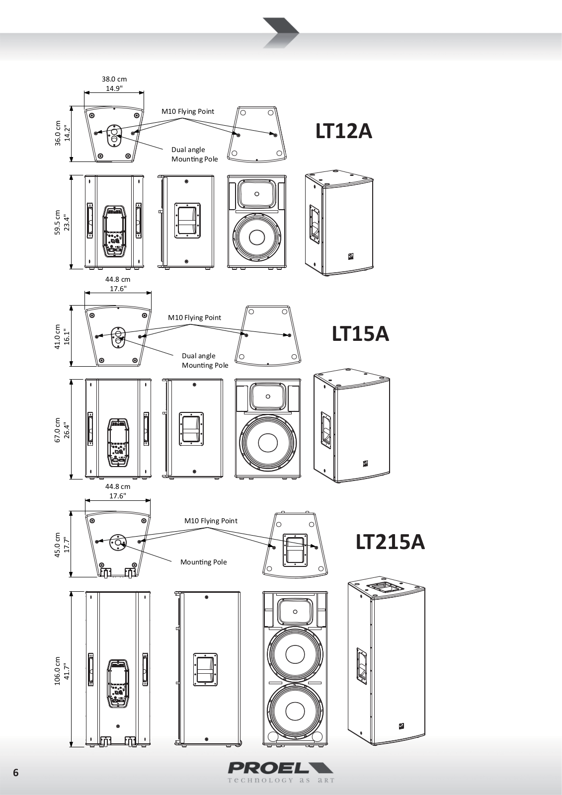
LT12A
LT12P
LT15A
2
LT215A
2
LT6A
LT6P
LT812A
2
LT8A
LT8P
LTS007C
M
M-1000
M-16
M1622USB
2
M-20
M-6
M602FX
2
M-8
2
M822
M822USB
2
M-8USB
2
MEG25
2
MFC568
Mi10
3
Mi12
3
Mi16
Mi5
Mi6
3
MIC62
MIC62W
MIX842
MIX843
MIX844
MLX2842
MLX3642
MO3T
MO3TW
MO5T
MO5TW
MO6T
MO6TW
Moving Head Led
MPLL
2
MQ10FX
MQ12USB
MQ16USB
MQ6
MQ6FX
MS 32
N
NEOS10A
NEOS10AXS
NEOS10P
NEOS10PX
NEOS115SA
NEOS115SP
Loading...
Loading...
Nothing found
LT6A
USER’S MANUAL
20 pgs
1.31 Mb
0
Table of contents
Loading...
Proel LT6A, LT8A, LT10A, LT12A, LT15A USER’S MANUAL
...
Proel LT6A, LT8A, LT10A, LT12A, LT15A, LT215A USER’S MANUAL
Download
Specifications and Main Features
Frequently Asked Questions
User Manual
Download
Loading...
+
hidden pages
Unhide
You need points to download manuals.
1 point = 1 manual.
You can buy points or you can get point for every manual you upload.
Buy points
Upload your manuals