

USER’S MANUAL
MANUALE UTENTE
www.proel.com

FCC COMPLIANCE NOTICE
This device complies with part 15 of the FCC rules. Operation is subject to the following two
conditions:
(1) This device may not cause harmful interference, and
(2) this device must accept any interference received, including interference that may cause
undesired operation.
CAUTION: Changes or modifi cations not expressly approved by the party responsible for
compliance could void the user’s authority to operate the equipment.
NOTE: This equipment has been tested and found to comply with the limits for a Class B digital
device, pursuant to part 15 of the FCC Rules. These limits are designed to provide reasonable
protection against harmful interference in a residential installation. This equipment generates,
uses, and can radiate radio frequency energy and, if not installed and used in accordance
with the instruction manual, may cause harmful interference to radio communications.
However, there is no guarantee that interference will not occur in a particular installation. If
this equipment does cause harmful interference to radio or television reception, which can
be determined by turning the equipment off and on, the user is encouraged to try to correct
the interference by one or more of the following measures:
• Reorient or relocate the receiving antenna.
• Increase the separation between the equipment and receiver.
• Connect the equipment into an outlet on a circuit different from that to which the receiver
is connected.
• Consult the dealer or an experienced radio/TV technician for help.
This marking shown on the product or its literature, indicates that it should not be disposed with other household wastes at the end of its
working life. To prevent possible harm to the enviroment or human health from uncontrolled waste disposal, please separate this from other
types of wastes and recycle it responsibly to promote the sustainable reuse of material resources. Household users should contact either
the retailer where they purchased this product, or their local government offi ce, for details of where and how they can take this item for
environmentally safe recycling. Business users should contact their supplier and check the terms and conditions of the purchase contract.
This product should not be mixed with other commercial wastes for disposal.
The lightning fl ash with arrowhead symbol within an equilateral triangle is intended to alert the user to the presence of uninsulated “dangerous
voltage” within the product’s enclosure, that may be of suffi cient magnitude to constitute a risk of electric shock to persons.
The exclamation point within an equilateral triangle is intended to alert the user to the presence of important operating and maintenance
(servicing) instructions in the literature accompanying the appliance.
The information contained in this publication has been carefully prepared and checked. However no responsibility will be taken for any errors. All
rights are reserved and this document cannot be copied, photocopied or reproduced in part or completely without written consent being obtained
in advance from PROEL. PROEL reserves the right to make any aesthetic, functional or design modifi cation to any of its products without any prior
notice. PROEL assumes no responsibility for the use or application of the products or circuits described herein.
Il marchio riportato sul prodotto o sulla documentazione indica che il prodotto non deve essere smaltito con altri rifi uti domestici al termine
del ciclo di vita. Per evitare eventuali danni all’ambiente si invita l’utente a separare questo prodotto da altri tipi di rifi uti e di riciclarlo in
maniera responsabile per favorire il riutilizzo sostenibile delle risorse materiali. Gli utenti domestici sono invitati a contattare il rivenditore
presso il quale è stato acquistato il prodotto o l’uffi cio locale preposto per tutte le informazioni relative alla raccolta differenziata e al
riciclaggio per questo tipo di prodotto. Gli utenti aziendali sono invitati a contattare il proprio fornitore e verifi care i termini e le condizioni
del contratto di acquisto. Questo prodotto non deve essere smaltito unitamente ad altri rifi uti commerciali.
Il simbolo del lampo con freccia in un triangolo equilatero intende avvertire l'utilizzatore per la presenza di "tensioni pericolose" non isolate
all'interno dell'involucro del prodotto, che possono avere una intensità suffi ciente a costituire rischio di scossa elettrica alle persone.
Il punto esclamativo in un triangolo equilatero intende avvertire l'utilizzatore per la presenza di importanti istruzioni per l'utilizzo e la
manutenzione nella documentazione che accompagna il prodotto.
Le informazioni contenute in questo documento sono state attentamente redatte e controllate. Tuttavia non è assunta alcuna responsabilità per
eventuali inesattezze. Tutti i diritti sono riservati e questo documento non può essere copiato, fotocopiato, riprodotto per intero o in parte senza previo
consenso scritto della PROEL. PROEL si riserva il diritto di apportare senza preavviso cambiamenti e modifi che estetiche, funzionali o di design a
ciascun proprio prodotto. PROEL non assume alcuna responsabilità sull’uso o sul l’applicazione dei prodotti o dei circuiti qui descritti.

3
INDICE / INDEX
MODEL HPX900 HPX1200 HPX2400 HPX2800
Power 8 ohm * 200 W 300 W 450 W 600 W
Power 4 ohm * 300 W 450 W 800 W 1000 W
Power 2 ohm ** 450 W 600 W 1200 W 1400 W
Power BRIDGE 8 ohm * 400 W 600 W 900 W 1200 W
Power BRIDGE 4 ohm ** 900 W 1200 W 2400 W 2800 W
Output Stage Class AB Class AB Class H Class H
Frequency response (+0/-0.5 dB) 20 Hz - 20 KHz 20 Hz - 20 KHz 20 Hz - 20 KHz 20 Hz - 20 KHz
Input Sensitivity (nominal) +2.3 dBu / 1.0 Vrms +1.0 dBu / 0.87 Vrms +0.8 dBu / 0.85 Vrms 0 dBu / 0.775Vrms
Input Sensitivity (fi xed gain) +8.3 dBu / 2.02 Vrms +4.0 dBu / 1.23 Vrms +5.8 dBu / 1.51 Vrms +7.0 dBu / 1.73 Vrms
GAIN (nominal/fi xed) 32 dB (40x) / 26 dB (20x) 35 dB (56x) / 32 dB (40x) 37 dB (71x) / 32 dB (40x) 39 dB (89x) / 32 dB (40x)
Input Connectors / Impedance XLR M, 1/4" JACK, RCA / 20 Kohm (balanced), 10 Kohm (unbalanced)
Output Connectors SPEAKON and Binding Post
Damping Factor > 100 > 100 > 200 > 200
Slew Rate > 20 V/uS > 20 V/uS > 20 V/uS > 20 V/uS
S/N Ratio (unweighted) > 85 dB > 86 dB > 90 dB > 91 dB
THD+N < 0.1% < 0.1% < 0.1% < 0.1%
Controls INPUT LEVEL, INPUT SENSITIVITY, STEREO/BRIDGE/PARALLEL, LOW PASS NOTCH (LPN), GND LIFT
LED Indicators POWER, ON, PARALLEL, BRIDGE, SIGNAL, LIMIT, PROTECT
Cooling Variable speed DC fan
Protections AC low power, DC, thermal, short circuit, VHF, CLIP limiter
Mains Supply Voltage 230 VAC (±10%) 50/60 Hz or 120VAC (±10%) 50/60 Hz
Maximum Consumption 1450 VA 1850 VA 3550 VA 4120 VA
Rated Consumption *** 200 VA 250 VA 450 VA 600 VA
Standby Consumption 50 VA 65 VA 65 VA 65 VA
Dimensions (W x H x D) 483 x 89 x 335 mm
19" x 3.5" x 13.2" (2U rack)
483 x 89 x 395 mm
19" x 3.5" x 15.6" (2U rack)
483 x 89 x 395 mm
19" x 3.5" x 15.6" (2U rack)
483 x 89 x 395 mm
19" x 3.5" x 15.6" (2U rack)
Weight 6 Kg (13.2 lb) 6.9 Kg (15.2 lb) 9.2 Kg (20.3 lb) 9.2 Kg (20.3 lb)
* RMS both channel THD < 1%
** 40 ms burst
*** Rated consumption is measured with pink noise with a crest factor of 12 dB, this can be considered a standard music program.
TECHNICAL SPECIFICATIONS SPECIFICHE TECNICHE
specifi cations
INDEX
FCC COMPLIANCE NOTICE . . . . . . . . . . . . . . . . . . . . . . . . . 2
TECHNICAL SPECIFICATIONS . . . . . . . . . . . . . . . . . . . . . . . 3
SETUP AND RACK MOUNTING (FIG. 1 / 2) . . . . . . . . . . . . 4
LOUDSPEAKER CABLE . . . . . . . . . . . . . . . . . . . . . . . . . . . . . 4
CONNECTIONS . . . . . . . . . . . . . . . . . . . . . . . . . . . . . . . . . . . 5
SUGGESTED CONFIGURATIONS . . . . . . . . . . . . . . . . . . . . . 5
LPN FILTER RESPONSE (FIG. 3) . . . . . . . . . . . . . . . . . . . . . . 5
CONTROL PANEL (FIG.4) . . . . . . . . . . . . . . . . . . . . . . . . . . . 6
REAR PANEL (FIG.5) . . . . . . . . . . . . . . . . . . . . . . . . . . . . . . . 6
CONFIGURATION EXAMPLES (FIG.6/7/8) . . . . . . . . . . . . . . 7
SAFETY AND PRECAUTIONS . . . . . . . . . . . . . . . . . . . . . . . 8
IN CASE OF FAULT . . . . . . . . . . . . . . . . . . . . . . . . . . . . . . . . 8
TROUBLESHOOTING . . . . . . . . . . . . . . . . . . . . . . . . . . . . . .8
CE CONFORMITY . . . . . . . . . . . . . . . . . . . . . . . . . . . . . . . . . . 9
PACKAGING, SHIPPING AND COMPLAINT . . . . . . . . . . . 9
WARRANTY AND PRODUCTS RETURN . . . . . . . . . . . . . . . 9
INSTALLATION AND DISCLAIMER . . . . . . . . . . . . . . . . . . . 9
POWER SUPPLY AND MAINTENANCE . . . . . . . . . . . . . . . 9
GENERAL INFORMATION . . . . . . . . . . . . . . . . . . . . . . . . . 10
SETUP AND RACK MOUNTING. . . . . . . . . . . . . . . . . . . . . 10
FRONT PANEL (FIG.4) . . . . . . . . . . . . . . . . . . . . . . . . . . . . . 10
REAR PANEL (FIG.5) . . . . . . . . . . . . . . . . . . . . . . . . . . . . . . 11
ADVANCED FEATURES . . . . . . . . . . . . . . . . . . . . . . . . . . . . 13
INDICE
SPECIFICHE TECNICHE . . . . . . . . . . . . . . . . . . . . . . . . . . . . 3
INSTALLAZIONE A RACK (FIG. 1 / 2). . . . . . . . . . . . . . . . . . 4
CAVO ALTOPARLANTE . . . . . . . . . . . . . . . . . . . . . . . . . . . . . 4
CONNESSIONI. . . . . . . . . . . . . . . . . . . . . . . . . . . . . . . . . . . . 5
CONFIGURAZIONI SUGGERITE . . . . . . . . . . . . . . . . . . . . . . 5
RISPOSTA FILTRO LPN (FIG. 3) . . . . . . . . . . . . . . . . . . . . . . 5
PANNELLO DI CONTROLLO (FIG.4) . . . . . . . . . . . . . . . . . . . 6
PANNELLO POSTERIORE (FIG.5) . . . . . . . . . . . . . . . . . . . . . 6
ESEMPI CONFIGURAZIONI (FIG.6/7/8) . . . . . . . . . . . . . . . . 7
AVVERTENZE PER LA SICUREZZA . . . . . . . . . . . . . . . . . . 14
IN CASO DI GUASTO . . . . . . . . . . . . . . . . . . . . . . . . . . . . . 14
PROBLEMATICHE COMUNI . . . . . . . . . . . . . . . . . . . . . . . . 14
CONFORMITÀ CE . . . . . . . . . . . . . . . . . . . . . . . . . . . . . . . . 15
IMBALLAGGIO, TRASPORTO E RECLAMI . . . . . . . . . . . . 15
GARANZIE E RESI . . . . . . . . . . . . . . . . . . . . . . . . . . . . . . . . 15
INSTALLAZIONE E LIMITAZIONI D’USO . . . . . . . . . . . . . 15
ALIMENTAZIONE E MANUTENZIONE . . . . . . . . . . . . . . . 15
INFORMAZIONI GENERALI . . . . . . . . . . . . . . . . . . . . . . . . 16
INSTALLAZIONE E MONTAGGIO A RACK . . . . . . . . . . . . 16
PANNELLO FRONTALE . . . . . . . . . . . . . . . . . . . . . . . . . . . . 16
PANNELLO POSTERIORE . . . . . . . . . . . . . . . . . . . . . . . . . . 17
FUNZIONI AVANZATE . . . . . . . . . . . . . . . . . . . . . . . . . . . .19

4
SETUP AND RACK MOUNTING (FIG. 1 / 2) INSTALLAZIONE A RACK (FIG. 1 / 2)
LOUDSPEAKER CABLE CAVO ALTOPARLANTE
FIG. 1 / 2
COLD AIR
FRONTALE
8U OPEN RACK
10U closed RACK
RACK aperto 8U
RACK chiuso 10U
POSTERIORE
FRONT REAR
FRONTALE POSTERIORE (chiuso)
FRONT REAR (closed)
ARIA FREDDA
COLD AIR
ARIA FREDDA
HOT AIR
HOT AIR
ARIA CALDA
ARIA CALDA
15 cm
6 inch
RECOMMENDED INSTALLATION
INSTALLAZIONE RACCOMANDATA
EVENTUAL INSTALLATION WITH CLOSED BACK
EVENTUALE INSTALLAZIONE CON RETRO CHIUSO
ENGLISH: Loudspeaker Line Losses (maximum permissible line lengths for 0.5dB losses, voltage or spl)
ITALIANO: Perdite di collegamento linee Altoparlanti (massima lunghezza possibile per perdite inferiori a 0.5dB, tensione o spl)
4 ohm load 8 ohm load Wire section data PROEL recommended cables
feet meter feet meter mm² AWG 2 wires 4 wires 2 wires Fire-resistant 4 wires Fire-resistant
75 25 150 50 4.0 12 HPC624 HPC644 HPC624FR
50 17.5 100 35 2.0 14 HPC620 HPC640 HPC520 HPC540
30 10 60 20 1.5 16 HPC610 HPC510
20 7.5 40 15 1.0 18 HPC605
this is a short extraction of the wide assortment of cables available from PROEL, please visit our website at www.proelgroup.com
FIG.1
FIG.2
5
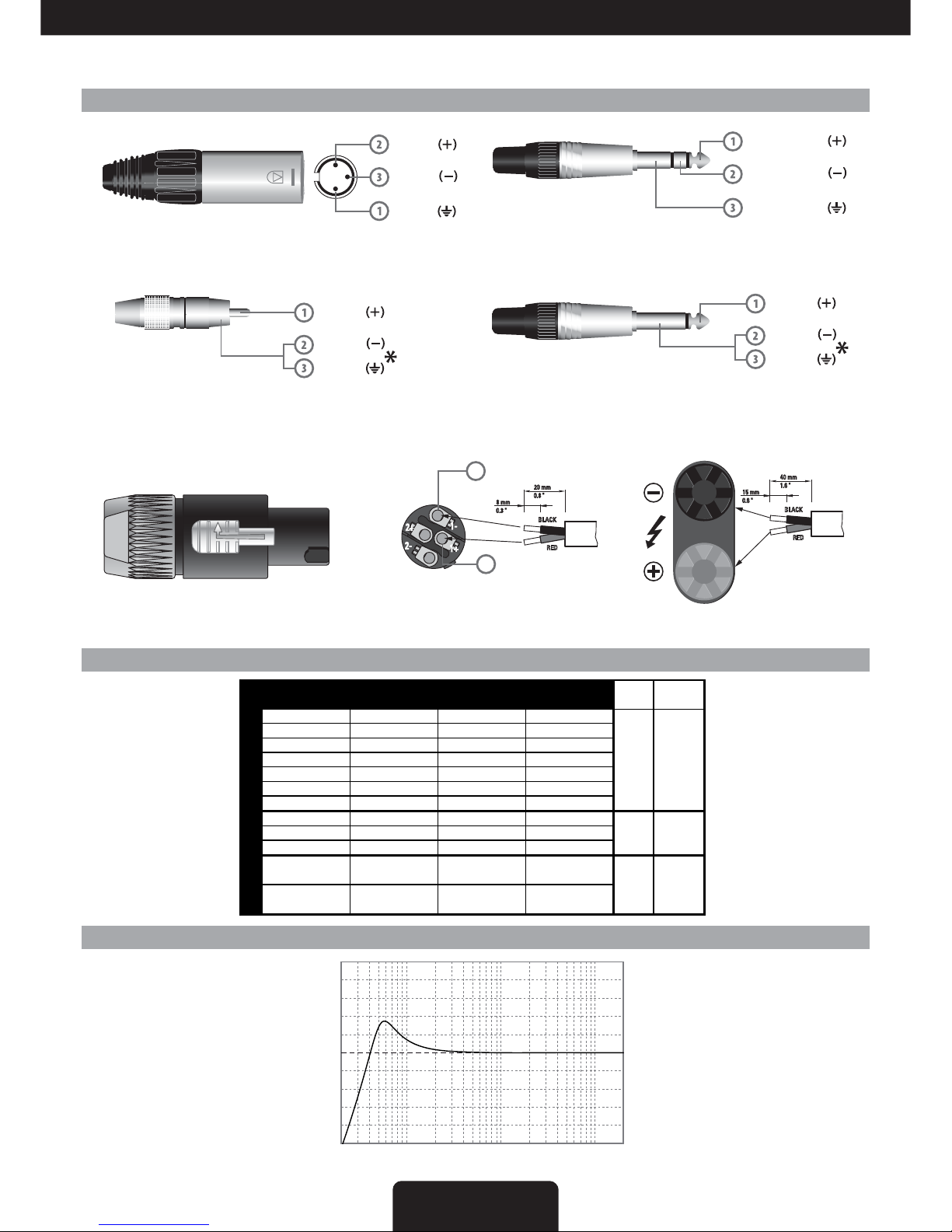
CONNECTIONS CONNESSIONI
connections
INPUT (ingresso)
Jack (bilanciato)
INPUT
Jack (balanced)
sleeve - gnd
tip - hot
ring - cold
INPUT (ingresso)
XLR bilanciato maschio
INPUT
Balanced male XLR
POWER OUTPUT - uscite altoparlanti
Connettore per cavo tipo Speakon Neutrik NL4
PROEL code - NL4FX
Codice PROEL - NL4FX
SPEAKER POWER OUTPUTS
uscite altoparlanti BINDING POST
BINDING POST speaker output
Neutrik NL4 Speakon Cable Connector
ground
hot
cold
INPUT (ingresso)
Jack (sbilanciato)
INPUT
Jack (unbalanced)
ground
tip - hot
cold
*nota: connettere insieme cold e ground
per cavi da bilanciato a sbilanciato
*note: connect both cold and ground
to make cable from balanced to unbalanced
2-
1+
2+
1-
20 mm
0.8 "
8 mm
0.3 "
RED
BLACK
positive / red / rosso
n.c.
1+
negative / black / nero
1-
n.c.
INPUT (ingresso)
RCA (sbilanciato)
INPUT
RCA (unbalanced)
ground
hot
cold
40 mm
1.6 "
15 mm
0.6 "
RED
BLACK
SUGGESTED CONFIGURATIONS
This table is a shortform of some sound
system examples
composed of PROEL
loudspeakers. These
are a few portion of
the speaker products
in catalogue at the
moment of printing.
CONFIGURAZIONI SUGGERITE
Questa tabella è un
riassunto di alcuni
esempi di sistema
composti con
altoparlanti PROEL.
Questa è una porzione
degli altoparlanti in
catalogo al momento
della stampa.
LPN FILTER RESPONSE (FIG. 3)
RISPOSTA FILTRO LPN (FIG. 3)
20 100 1K 10K 20K
-15
-12
-9
-6
-3
0
+3
+6
+9
+12
+15
f (Hz)
dB
H
HPX900 HPX1200 HPX2400 HPX2800
4x FLASH5P 2x FLASH15P 2x NET15P 2x SW118P
2x FLASH8P 2x EX215P4 2x NET215P4 2x NEOS122P
2x FLASH12P 2x EX18SP 2x NEOS15P
2x EX15P/MP 2x EX218SP4
2x EX15SP 2x NET12P
2x NET10P 2x SW115P
2x NEOS10P 2x NEOS12P
1x NET15P 1x NEOS122P 1x NEOS152P 1x NEOS218SP
1x NEOS15P 1x SW118P 1x NEOS118SP
1x NEOS215SP
2x SW110P +
2x FLASH5P
2x SW115P +
2x FLASH8P
2x SW115P +
2x FLASH8P
STEREO
systems
LOUDSPEAKERS
AMPLIFIERS
STEREO or
PARALLEL
set as:
BRIDGE
example
figures:
6
7
8
6
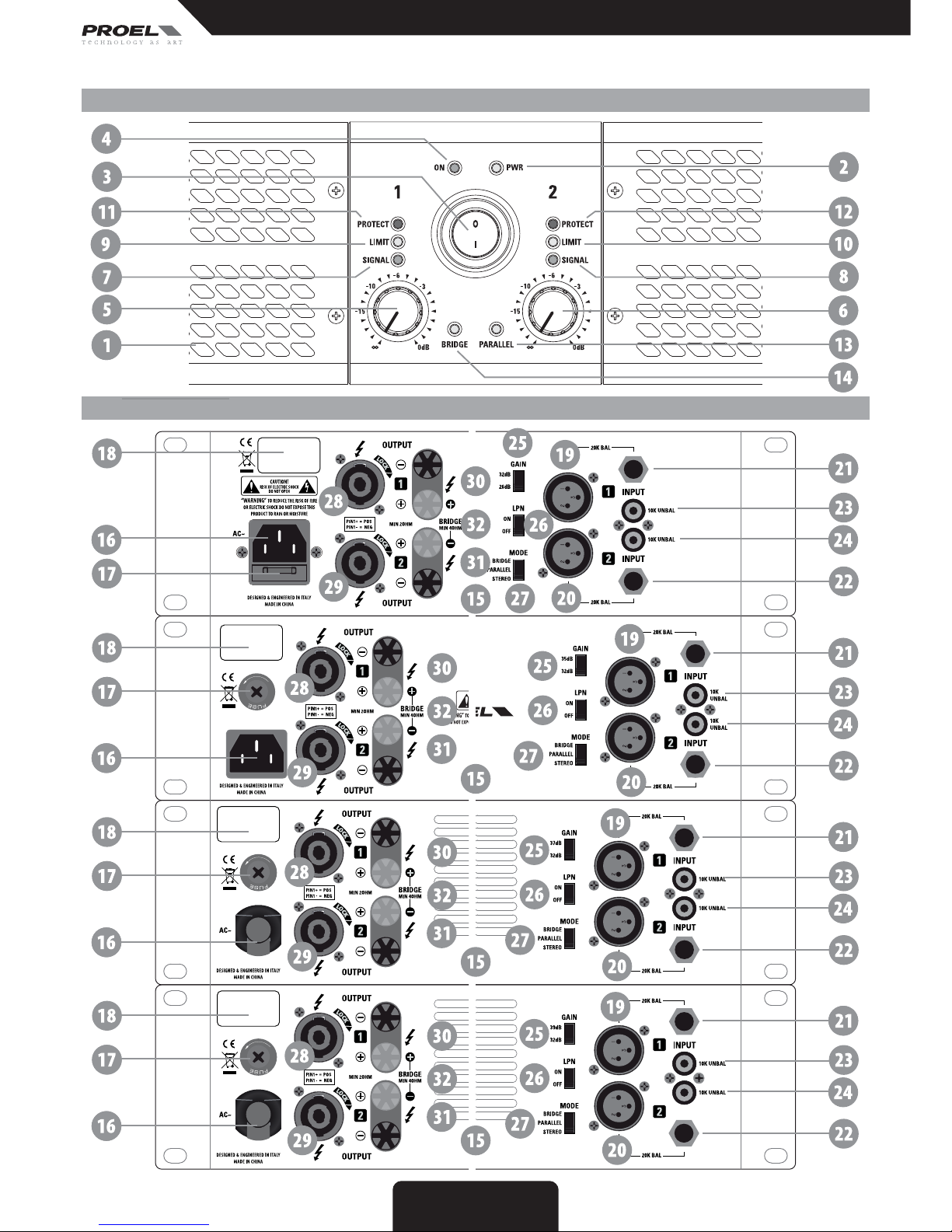
REAR PANEL (FIG.5) PANNELLO POSTERIORE (FIG.5)
CONTROL PANEL (FIG.4) PANNELLO DI CONTROLLO (FIG.4)
FIG. 3 / 4
HPX900
HPX1200
HPX2400
HPX2800
 Loading...