


USER’S MANUAL y MANUALE D’USO
www.proelgroup.com
english italiano
2
ENG ITA
SAFETY AND PRECAUTIONS
AVVERTENZE PER LA SICUREZZA
FCC COMPLIANCE NOTICE
This is a class A digital device, which is marked for use in a commercial, industrial or business environment,
exclusive of used by the general public or used in the home.
This device complies with Part 15 of the FCC Rules. Operation is subject to the following two conditions:
(1) this device may not cause harmful interference, and
(2) this device must accept any interference received, including interference that may cause undesired
operation.
CAUTION: Changes or modications to this product not expressly approved by the manufacturer could void
the user's authority to operate this product.
NOTE: This equipment has been tested and found to comply with the limits for a Class A digital device, pursuant
to Part 15 of FCC Rules. These limits are designed to provide reasonable protection against harmful interference
when the equipment is operated in a commercial environment. This equipment generates, uses and can radiate
radio frequency energy and, if not installed and used in accordance with the instruction manual, may cause
harmful interference to radio communications. Operations of this equipment in a residential area is likely to
cause harmful interference in which case the user will be required to correct the interference at his own
expense.
3
ENG ITA
AVVERTENZE PER LA SICUREZZA
SAFETY AND PRECAUTIONS
Il marchio riportato sul prodotto o sulla documentazione indica che il prodotto non
deve essere smaltito con altri ri uti domestici al termine del ciclo di vita. Per evitare
eventuali danni all’ambiente si invita l’utente a separare questo prodotto da altri tipi
di ri uti e di riciclarlo in maniera responsabile per favorire il riutilizzo sostenibile delle
risorse materiali. Gli utenti domestici sono invitati a contattare il rivenditore presso il
quale è stato acquistato il prodotto o l’u cio locale preposto per tutte le informazioni
relative alla raccolta di erenziata e al riciclaggio per questo tipo di prodotto. Gli utenti aziendali sono
invitati a contattare il proprio fornitore e veri care i termini e le condizioni del contratto di acquisto.
Questo prodotto non deve essere smaltito unitamente ad altri ri uti commerciali.
Il simbolo del lampo con freccia in un triangolo equilatero intende avvertire
l'utilizzatore per la presenza di "tensioni pericolose" non isolate all'interno
dell'involucro del prodotto, che possono avere una intensità su ciente a costituire
rischio di scossa elettrica alle persone.
Il punto esclamativo in un triangolo equilatero intende avvertire l'utilizzatore
per la presenza di importanti istruzioni per l'utilizzo e la manutenzione nella
documentazione che accompagna il prodotto.
AVVERTENZE PER LA SICUREZZA
• ATTENZIONE - Durante le fasi di uso o manutenzione, devono essere prese alcune precauzioni
onde evitare danneggiamenti alle strutture meccaniche ed elettroniche del prodotto.
Prima di utilizzare il prodotto, si prega di leggere attentamente le seguenti istruzioni per la
sicurezza. Prendere visione del manuale d’uso e conservarlo per successive consultazioni:
– In presenza di bambini, controllare che il prodotto non rappresenti un pericolo.
– Posizionare l’apparecchio al riparo dagli agenti atmosferici e a distanza di sicurezza dall’acqua,
dalla pioggia e dai luoghi ad alto grado di umidità.
– Collocare o posizionare il prodotto lontano da fonti di calore quali radiatori, griglie di
riscaldamento e ogni altro dispositivo che produca calore.
– Collocare o posizionare il prodotto in modo che non ci siano ostruzioni alla sua propria ventilazione
e dissipazione di calore. Non installare in uno spazio limitato.
– Evitare che qualsiasi oggetto o sostanza liquida entri all’interno del prodotto.
– Il prodotto deve essere connesso esclusivamente alla rete elettrica delle caratteristiche descritte
nel manuale d’uso o scritte sul prodotto, usando esclusivamente il cavo rete in dotazione e
controllando sempre che sia in buono stato, in particolare la spina e il punto in cui il cavo esce dal
prodotto.
– Non annullare la sicurezza garantita dall'uso di spine polarizzate o con messa a terra.
– Fare attenzione che il punto di alimentazione della rete elettrica sia dotato di una e ciente presa
di terra.
– Disconnettere il prodotto dalla rete elettrica durante forti temporali o se non viene usato per un
lungo periodo di tempo.
– Non disporre oggetti sul cavo di alimentazione, non disporre i cavi di alimentazione e segnale
in modo che qualcuno possa incianparci. Altresì non disporre l’apparecchio sui cavi di altri apparati.
Installazioni inappropriate di questo tipo possono creare la possibilità di rischio di incendio e/o danni
alle persone.
– Questo prodotto può essere capace di produrre livelli sonori che possono causare perdite d’udito
permanenti. Si raccomanda di evitare l’esposizione ad alti livelli sonori o livelli non confortevoli per
lunghi periodi di tempo. Se si notano perdite d’udito o acufeni ( schii) consultare un audiologo. La
sensibilità alla perdita di udito causata da eccessiva esposizione al rumore varia considerevolmente
da individuo a individuo, ma mediamente ciascuno può accusare perdita di udito se esposto al rumore
per un certo periodo di tempo. Come suggerimento viene riportata la tabella dei tempi massimi di
esposizione giornaliera al rumore al ne di evitare perdite di udito, fonte della tabella è l'ente per
la salute degli Stati Uniti (OSHA):
Ore di esposizione
giornaliera
Livello sonoro in dBA
costante di tempo SLOW
Esempio
Tipico
8 90 Duo acustico in un piccolo club
692
4 95 Treno metropolitano
397
2 100 Musica classica molto forte
1.5 102
1 105 Rumore da tra co urbano intenso
0.5 110
0.25 or less 115 Parte più rumorosa di un concerto rock
Si fà presente inoltre che sia i bambini che gli animali domestici sono più sensibili al rumore
intenso.
This marking shown on the product or its literature, indicates that it should not
be disposed with other household wastes at the end of its working life. To prevent
possible harm to the enviroment or human health from uncontrolled waste disposal,
please separate this from other types of wastes and recycle it responsibly to promote
the sustainable reuse of material resources. Household users should contact either the
retailer where they purchased this product, or their local government o ce, for details
of where and how they can take this item for environmentally safe recycling. Business users should
contact their supplier and check the terms and conditions of the purchase contract. This product
should not be mixed with other commercial wastes for disposal.
The lightning ash with arrowhead symbol within an equilateral triangle is intended
to alert the user to the presence of uninsulated “dangerous voltage” within the
product’s enclosure, that may be of su cient magnitude to constitute a risk of
electric shock to persons.
The exclamation point within an equilateral triangle is intended to alert the user to
the presence of important operating and maintenance (servicing) instructions in the
literature accompanying the appliance.
SAFETY AND PRECAUTIONS
• CAUTION - Before using this product read carefully the following safety instructions. Take a look
of this manual entirely and preserve it for future reference.
When using any electric product, basic precautions should always be taken, including the
following:
– To reduce the risk, close supervision is necessary when the product is used near children.
– Protect the apparatus from atmospheric agents and keep it away from water, rain and high
humidity places.
– This product should be site away from heat sources such as radiators, lamps and any other device
that generate heat.
– This product should be located so that its location or position does not interfere with its proper
ventilation and heating dissipation. Do not install in a con ned space.
– Care should be taken so that objects and liquids do not go inside the product.
– The product should be connected to a power supply mains line only of the type described on the
operating instructions or as marked on the product. Connect the apparatus to a power supply using
only power cord included making always sure it is in good conditions, specially the plug and the point
where it exit from the apparatus.
– Do not cancel the safety feature assured by means of a polarized line plug (one blade wider than
the other) or with a earth connection.
– Make sure that power supply mains line has a proper earth connection.
– Power supply cord should be unplugged from the outlet during strong thunderstorm or when left
unused for a long period of time.
– Do not place objects on the product’s power cord or place it in a position where anyone could
trip over, walk on or roll anything over it. Do not allow the product to rest on or to be installed over
power cords of any type. Improper installations of this type create the possibility of re hazard and/or
personal injury.
– This product in combination with loudspeakers may be capable of producing sound levels that
could cause permanent hearing loss. Exposure to extremely high noise levels may cause permanent
hearing loss. Individuals vary considerably in susceptibility to noise-induced hearing loss, but nearly
everyone will lose some hearing if exposed to su ciently intense noise for a period of time. The U.S.
Government’s Occupational Safety and Health Administration (OSHA) has speci ed the permissible
noise level exposures shown in the following chart. According to OSHA, any exposure in excess of
these permissible limits could result in some hearing loss. To ensure against potentially dangerous
exposure to high sound pressure levels, it is recommended that all persons exposed to equipment
capable of producing high sound pressure levels use hearing protectors while the equipment is in
operation. Ear plugs or protectors in the ear canals or over the ears must be worn when operating
the equipment in order to prevent permanent hearing loss if exposure is in excess of the limits set
forth here.
Duration Per Day
In Hours
Sound Level dBA
Slow Response
Typi ca l
Example
8 90 Duo in small club
692
4 95 Subway Train
397
2 100 Very loud classical music
1.5 102
1 105 Tra c noise
0.5 110
0.25 or less 115 Loudest parts at a rock concert
4
ENG ITA
SAFETY AND PRECAUTIONS
AVVERTENZE PER LA SICUREZZA
IN CASO DI GUASTO
• In caso di guasto o manutenzione questo prodotto deve essere ispezionato da personale
quali cato quando:
– Ci sono difetti sulle connessioni o sui cavi di collegamento in dotazione.
– Sostanze liquide sono penetrate all’interno del prodotto.
– Il prodotto è caduto e si è danneggiato.
– Il prodotto non funziona normalmente esibendo una marcato cambio di prestazioni.
– Il prodotto perde sostanze liquide o gassose o ha l’involucro danneggiato.
• Non intervenire sul prodotto.
• Rivolgersi a un centro di assistenza autorizzato Proel.
CONFORMITÀ CE
• I Prodotti Proel sono conformi alla direttiva 73/23/EEC (LVD) e successive modi che 93/68/EEC,
secondo lo standard EN 60065 e alla direttiva 89/336/EEC (EMC) e successive modi che 92/31/EEC e
93/68/EEC, secondo gli standard EN 55103-1 ed EN 55103-2 con le seguenti restrizioni ambientali:
E4 - ambiente controllato di EMC (per esempio gli studi di registrazione o di radiotrasmissione),
e l’ambiente esterno rurale (lontano dalle linee ferroviarie, dai trasmettitori, dalle linee
elettriche aree ecc.)
E5 - industria pesante e ambienti vicini ai trasmettitori di radiodi usione
IMBALLAGGIO, TRASPORTO E RECLAMI
• L’imballo è stato sottoposto a test di integrità secondo la procedura ISTA 1A. Si raccomanda di
controllare il prodotto subito dopo l’apertura dell’imballo.
• Se vengono riscontrati danni informare immediatamente il rivenditore. Conservare quindi
l’imballo completo per permetterne l’ispezione.
• Proel declina ogni responsabilità per danni causati dal trasporto.
• Le merci sono vendute “franco nostra sede” e viaggiano sempre a rischio e pericolo del
distributore.
• Eventuali avarie e danni dovranno essere contestati al vettore. Ogni reclamo per imballi
manomessi dovrà essere inoltrato entro 8 giorni dal ricevimento della merce.
GARANZIE E RESI
• I Prodotti Proel sono provvisti della garanzia di funzionamento e di conformità alle proprie
speci che, come dichiarate dal costruttore.
• La garanzia di funzionamento è di 24 mesi dopo la data di acquisto. I difetti rilevati entro il
periodo di garanzia sui prodotti venduti, attribuibili a materiali difettosi o difetti di costruzione,
devono essere tempestivamente segnalati al proprio rivenditore o distributore, allegando evidenza
scritta della data di acquisto e descrizione del tipo di difetto riscontrato. Sono esclusi dalla garanzia
difetti causati da uso improprio o manomissione. Proel SpA constata tramite veri ca sui resi la
difettosità dichiarata, correlata all’appropriato utilizzo, e l’e ettiva validità della garanzia; provvede
quindi alla sostituzione o riparazione dei prodotti, declinando tuttavia ogni obbligo di risarcimento
per danni diretti o indiretti eventualmente derivanti dalla difettosità.
INSTALLAZIONE E LIMITAZIONI D’USO
• I Prodotti Proel sono destinati esclusivamente ad un utilizzo speci co di tipo sonoro: segnali di
ingresso di tipo audio (20Hz-20kHz). Proel declina ogni responsabilità per danni a terzi causati da
mancata manutenzione, manomissioni, uso improprio o installazione non eseguita secondo le norme
di sicurezza.
• L'installazione di questi amplificatori è prevista su rack 19" ventilati per prodotti ad uso
professionale. Questi ampli catori prevedono fori di ventilazione sul frontale e sul retro del prodotto.
Evitare assolutamente di ostruire la ventilazione fronte-retro dell'apparecchio onde prevenire alte
temperature al suo interno, che potrebbero provocare guasti pericolosi e incendio.
• Non installare apparecchi con un alta sensibilità e un alto guadagno quali mixer, preampli catori,
registratori, unità di conversione AD/DA etc. direttamente sopra o sotto questi ampli catori. Siccome
questi ampli catori hanno una notevole potenza generano un forte campo elettromagnetico che
può causare disturbi in apparecchi privi di un adeguata schermatura nelle proprie vicinanze. Se un
ampli catore ed uno uno di questi apparecchi sensibili è installato nello stesso rack si raccomanda
di installare l'ampli catore nella posizione più bassa e l'apparecchio sensibile nella posizione più
alta.
• Installare questi amplificatori il più lontano possibile da radioricevitori e televisori. Un
ampli catore installato in prossimità di questi apparati può causare interferenza e rumore con
conseguente degrado della ricezione di immagini e suoni.
• La Proel S.p.a. si riserva di modi care il prodotto e le sue speci che senza preavviso.
• Proel declina ogni responsabilità per danni a terzi causati da mancata manutenzione,
manomissioni, uso improprio o installazione non eseguita secondo le norme di sicurezza e a regola
d'arte.
IN CASE OF FAULT
• In case of fault or maintenance this product should be inspected only by quali ed service
personnel when:
– There is a aw either in the connections or in the supplied connecting cables.
– Liquids have spilled inside the product.
– The product has fallen and been damaged.
– The product does not appear to operate normally or exhibits a marked change in performance.
– The product has been losted liquids or gases or the enclosure is damaged.
• Do not operate on the product, it has no user-serviceable par ts inside.
• Refer ser vicing to an authorized maintenance centre.
CE CONFORMITY
• Proel products comply with directive 73/23/EEC (LVD) and following modi cations 93/68/EEC,
as stated in EN 60065 standard and with directive 89/336/EEC (EMC) and following modi cations
92/31/EEC and 93/68/EEC, as stated in EN 55103-1 and EN 55103-2 standards with the following
enviroment restrictions:
E4 - controlled EMC environment (for example purpose built broadcasting or recording studio),
and the rural outdoors environment (far away from railways, transmitters, overhead power
lines, etc.).
E5 - heavy industrial and environments close to broadcast transmitters.
PACKAGING, SHIPPING AND COMPLAINT
• This unit package has been submitted to ISTA 1A integrity tests. We suggest you control the unit
conditions immediately after unpacking it.
• If any damage is found, immediately advise the dealer. Keep all unit packaging parts to allow
inspection.
• Proel is not responsible for any damage that occurs during shipment.
• Products are sold “delivered ex warehouse” and shipment is at charge and risk of the buyer.
• Possible damages to unit should be immediately noti ed to forwarder. Each complaint for
manumitted package should be done within eight days from product receipt.
WARRANTY AND PRODUCTS RETURN
• Proel products have operating warranty and comply their specifications, as stated by
manufacturer.
• Proel warrants all materials, workmanship and proper operation of this product for a period of two
years from the original date of purchase. If any defects are found in the materials or workmanship
or if the product fails to function properly during the applicable warranty period, the owner should
inform about these defects the dealer or the distributor, providing receipt or invoice of date of
purchase and defect detailed description. This warranty does not extend to damage resulting from
improper installation, misuse, neglect or abuse. Proel S.p.A. will verify damage on returned units,
and when the unit has been properly used and warranty is still valid, then the unit will be replaced
or repaired. Proel S.p.A. is not responsible for any "direct damage" or "indirect damage" caused by
product defectiveness.
INSTALLATION AND DISCLAIMER
• Proel products have been expressly designed for audio application, with signals in audio
range (20Hz to 20kHz). Proel has no liability for damages caused in case of lack of maintenance,
modi cations, improper use or improper installation non-applying safety instructions.
• These ampli ers are adapted in a properly ventilated, standard professional 19" rack. These units
feature ventilation holes on the front and back panels. Absolutely do not obstruct the ventilation
holes. Blocked ventilation can cause damages and re.
• Do not locate sensitive high-gain equipment such as mixer, preampli ers, recorders or AD/DA
conversion units directly above or below these ampli ers. Because these ampli ers have a high
power density, it ha a strong magnetic eld which can induce hum into unshielded devices that are
located nearby. If an equipment rack is used, we recommend locating the ampli er in the bottom of
the rack and the mixer, preampli er or other sensitive equipment at the top.
• Proel S.p.A. reserves the right to change these speci cations at any time without notice.
• Proel S.p.A. declines any liability for damages to objects or persons caused by lacks of
maintenance, improper use, installation not performed with safety precautions and at the state of
the art.
5
ENG ITA
CONTENTS
INDICE
CONTENTS
SAFETY AND PRECAUTIONS . . . . . . . . . . . . . . . . . . . . . . . . . . . . . . . . . .3
IN CASE OF FAULT . . . . . . . . . . . . . . . . . . . . . . . . . . . . . . . . . . . . . . . . . .3
CE CONFORMITY . . . . . . . . . . . . . . . . . . . . . . . . . . . . . . . . . . . . . . . . . . .4
PACKAGING, SHIPPING AND COMPLAINT . . . . . . . . . . . . . . . . . . . . . . .4
WARRANTY AND PRODUCTS RETURN . . . . . . . . . . . . . . . . . . . . . . . . . .4
INSTALLATION AND DISCLAIMER . . . . . . . . . . . . . . . . . . . . . . . . . . . . . .4
POWER SUPPLY AND MAINTENANCE . . . . . . . . . . . . . . . . . . . . . . . . . .4
INTRODUCTION . . . . . . . . . . . . . . . . . . . . . . . . . . . . . . . . . . . . . . . . . . . .6
SETUP AND RACK MOUNTING . . . . . . . . . . . . . . . . . . . . . . . . . . . . . . . .6
FRONT PANEL . . . . . . . . . . . . . . . . . . . . . . . . . . . . . . . . . . . . . . . . . . . . .8
REAR PANEL . . . . . . . . . . . . . . . . . . . . . . . . . . . . . . . . . . . . . . . . . . . . 10
ADVANCED FEATURES . . . . . . . . . . . . . . . . . . . . . . . . . . . . . . . . . . . . 13
CONNECTIONS . . . . . . . . . . . . . . . . . . . . . . . . . . . . . . . . . . . . . . . . . . . 15
DIMENSIONS . . . . . . . . . . . . . . . . . . . . . . . . . . . . . . . . . . . . . . . . . . . . 16
CONNECTION EXAMPLES . . . . . . . . . . . . . . . . . . . . . . . . . . . . . . . . . . 17
TROUBLESHOOTING . . . . . . . . . . . . . . . . . . . . . . . . . . . . . . . . . . . . . . 21
HP•D3400
PFC
TECHNICAL SPECIFICATIONS . . . . . . . . . . . . . . . . . . . 22
INDICE
AVVERTENZE PER LA SICUREZZA . . . . . . . . . . . . . . . . . . . . . . . . . . . . . .3
IN CASO DI GUASTO . . . . . . . . . . . . . . . . . . . . . . . . . . . . . . . . . . . . . . . .3
CONFORMITÀ CE . . . . . . . . . . . . . . . . . . . . . . . . . . . . . . . . . . . . . . . . . . .3
IMBALLAGGIO, TRASPORTO E RECLAMI . . . . . . . . . . . . . . . . . . . . . . . .3
GARANZIE E RESI . . . . . . . . . . . . . . . . . . . . . . . . . . . . . . . . . . . . . . . . . .4
INSTALLAZIONE E LIMITAZIONI D’USO . . . . . . . . . . . . . . . . . . . . . . . . .4
ALIMENTAZIONE E MANUTENZIONE . . . . . . . . . . . . . . . . . . . . . . . . . . .4
INTRODUZIONE . . . . . . . . . . . . . . . . . . . . . . . . . . . . . . . . . . . . . . . . . . . .6
INSTALLAZIONE E MONTAGGIO A RACK . . . . . . . . . . . . . . . . . . . . . . . .6
PANNELLO FRONTALE . . . . . . . . . . . . . . . . . . . . . . . . . . . . . . . . . . . . . . .8
PANNELLO POSTERIORE . . . . . . . . . . . . . . . . . . . . . . . . . . . . . . . . . . . 10
FUNZIONI AVANZATE . . . . . . . . . . . . . . . . . . . . . . . . . . . . . . . . . . . . . 13
CONNESSIONI . . . . . . . . . . . . . . . . . . . . . . . . . . . . . . . . . . . . . . . . . . . 15
DIMENSIONI . . . . . . . . . . . . . . . . . . . . . . . . . . . . . . . . . . . . . . . . . . . . 16
ESEMPI DI CONNESSIONE . . . . . . . . . . . . . . . . . . . . . . . . . . . . . . . . . . 17
PROBLEMATICE COMUNI . . . . . . . . . . . . . . . . . . . . . . . . . . . . . . . . . . 21
HP•D3400
PFC
SPECIFICHE TECNICHE . . . . . . . . . . . . . . . . . . . . . . . . 22
POWER SUPPLY AND MAINTENANCE
• Clean only with dry cloth.
• Check periodically that the slots for its proper ventilation and heating dissipation are not
obstructed by dust, remove the dust using a dry brush or a compressed air gun.
• The HPD3400PFC ampli er of Proel has been designed with CLASS I construction and must be
connected always to a mains socket outlet with a proctetive earth connection (the third grounding
prong).
• Before connecting the product to the mains outlet make certain that the mains line voltage
matches that shown on the rear of the product:
150 - 264 V range for 230 V nominal voltage model or
85 - 132 V range for 120 V nominal voltage model.
• To disconnect these equipment from the AC Mains, disconnect the power supply cord plug from the
AC receptacle.
• THE REPLACEMENT OF FUSES INSIDE THE APPARATUS MUST BE MADE ONLY BY
QUALIFIED PERSONNEL.
• CHECK THE CONDITION OF THE PROTECTION FUSE, ACCESSIBLE OUTWARD, ONLY
WITH THE APPARATUS SWITCHED OFF AND DISCONNECTED FROM THE MAINS LINE
OUTLET.
• REPLACE THE PROTECTION FUSE ONLY WITH SAME TYPE AS SHOWN ON THE
PRODUCT.
• IF AFTER THE SUBSTITUTION, THE FUSE INTERRUPTS AGAIN THE APPARATUS
WORKING, DO NOT TRY AGAIN THEN CONTACT THE PROEL SERVICE CENTER.
ALIMENTAZIONE E MANUTENZIONE
• Pulire il prodotto unicamente con un panno asciutto.
• Controllare periodicamente che le aperture di ra redamento non siano ostruite da accumuli di
polvere, provvedere alla rimozione della polvere mediante un pennello o aria compressa.
• L'ampli catore HPD3400PFC della Proel è costruito in CLASSE I e prevede sempre il collegamento
mediante presa di corrente con terminale di terra di protezione (terzo terminale di terra).
• Prima di collegare l'apparecchio alla presa di corrente, accertatevi che la tensione di rete corrisponda
a quella indicata sul retro dell’apparato:
tra 150 e 264 V per il modello con la tensione nominale di 230 V
tra 85 e 132 V per il modello con la tensione nominale di 120V.
• Per scollegare completamente questi apparecchi dalla rete estrarre la spina di alimentazione dalla
presa di corrente.
• LA SOSTITUZIONE DI FUSIBILI ALL'INTERNO DELL'APPARATO È CONSENTITO
ESCLUSIVAMENTE A PERSONALE QUALIFICATO.
• CONTROLLARE LO STATO DEI FUSIBILI DI PROTEZIONE ESCLUSIVAMENTE AD
APPARATO SPENTO E DISCONNESSO DALLA RETE ELETTRICA.
• RIMPIAZZARE IL FUSIBILE DI PROTEZIONE ESCLUSIVAMENTE CON UN FUSIBILE CON
LE MEDESIME CARATTERISTICHE RIPORTATE SUL PRODOTTO.
• SE DOPO LA SOSTITUZIONE, IL FUSIBILE INTERROMPE NUOVAMENTE IL
FUNZIONAMENTO DELL'APPARATO, NON INSISTERE E CONTATTARE IL SERVIZIO
ASSISTENZA PROEL.

6
ENG ITA
SETUP & RACK MOUNTING
INSTALLAZIONE E MONTAGGIO A RACK
INTRODUCTION
Thank you for having chosen a PROEL ampli er.
The new HP-3400PFC professional power ampli er is the result of a deep
and meticulous stylistic and functional research merged into a high
quality and reliable product, essential device both in xed installations
and TOURING applications.
The powerful performances of the HP-3400PFC amplifier satisfy an
exceptionally wide range of ampli cation needs: live touring gigs, dance
oors, sport venues, opera and drama theathres, worship venues, theme
parks, cinema theathres, television studio and so on.
The HP-3400PFC high performances consist of the following features:
• two indipendent channels, parallel or bridge con gurable, fully made
with switching technology with output stages in class-D shape.
• the supply circuit include the PFC (Power Factor Correction), able to
guarantee that the AC input current wave form is sinusoidal and in phase
with the mains voltage wave form, the PFC circuit ensure low rated
consumption and provides full output power with any mains voltage
condition (150 V - 264 V: 230 V model, 85 V -132 V: 120 V model).
• the ampli er is equipped with a Soft Clipping limiter that gives an
undistorted output signal in any input signal condition.
• the protection system includes thermal protection, short circuit
protection and high frequency (over audio range) protection circuits.
• several user configurations can be selected in the input section
(STEREO/BRIDGE/PARALLEL) as well as several ltering options (FLAT/
BIAMP/HPF).
• the ampli er is tted in 2 standard rack unit only.
To make the best use of this ampli er, please read the manual thoroughly
before operating. Let's go!
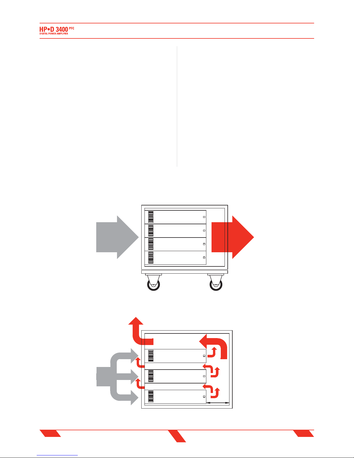
SETUP AND RACK MOUNTING
All HP-D ampli ers will mount in two units of a standard 19" (48.3cm)
rack, the front panel is provided of four
mounting holes. HP-D amplifiers uses a
forced-air cooling system to mantain a
low operating temperature. Drawn by an
internal fan, cold air enters through the
slots in the front panel and flows over
and through internal components, then
the hot air gets out from the rear panel
slots. The HP-D amplifiers drive the fan
using a variable-speed DC circuit, which
is controlled by sensing the heat sink
temperature. The fan speed will increase
only when the temperature of either heat
sink requires it, which keeps fan noise to a
minimum and helps cut dust accumulation
inside.
NOTE: In order to prevent the dust
accumulation inside the ampli er, the
two air vents on front panel have a dust
filter. Each time these filters are dirty
(it depends on enviroment conditions)
you have to remove the air slots using a
phillips screwdriver (as shown on gure)
INTRODUZIONE
Grazie per aver scelto un ampli catore PROEL.
Il nuovo ampli catore di potenza professionale HP-3400PFC è frutto
di un’intensa e meticolosa ricerca stilistica e funzionale confluita in
un prodotto di alta qualità ed affidabilità, fondamentale sia per le
installazioni sse che per le applicazioni TOURING.
Le prestazioni del nuovo finale di potenza HP-3400PFC sono tali da
soddisfare una vastissima gamma di applicazioni del settore professionale:
concerti in tour, discoteche, palazzetti, teatri di opera e di prosa, luoghi di
culto, parchi a tema, sale cinematogra che, studi televisivi, etc.
Le alte prestazioni consistono delle seguenti caratteristiche:
• due canali indipendenti realizzati completamente in tecnologia
switching con stadi di uscita in con gurazione classe-D.
• l'alimentazione con circuito PFC (correzione del fattore di potenza)
è in grado di mantenere in fase e con la stessa forma d'onda la corrente
assorbita con la tensione, garantendo un minor consumo e l’erogazione
della massima potenza con qualsiasi tensione di alimentazione (150
V - 264 V: modello 230 V, 85 V -132 V: modello 120 V).
• l'ampli catore è fornito di un limiter Soft Clipping che garantisce una
uscita indistorta per qualsiasi livello del segnale d'ingresso.
• il sistema di protezioni include la protezione termica, la protezione da
corto circuito e la protezione dalle frequenze oltre lo spettro udibile.
• diverse tipi di con gurazioni possono essere impostate dalla sezione
ingressi (STEREO/BRIDGE/PARALLEL) come pure diverse opzioni di
ltraggio (FLAT/BIAMP/HPF).
• l'ampli catore è inseribile in solo 2 unità rack standard.
Per una installazione ed un uso corretto dell'amplificatore, leggete
attentamente tutto il manuale. Pronti ... Via!
INSTALLAZIONE E MONTAGGIO A RACK
Tutti gli ampli catori HP-D è previsto che siano montati su due unità
di un rack standard da 19" (48.3cm), il
pannello frontale è provvisto di quattro fori
per il ssaggio al rack. Gli ampli catori HP-D
usano un sistema di ra redamento ad aria
forzata per mantenere una temperatura
di esercizio bassa. L'aria fredda, aspirata
dalla ventola interna, entra attraverso le
fessure sul pannello frontale e scorre sui
componenti interni raffredandoli, quindi
l'aria calda esce dalle fessure del pannello
posteriore. Gli ampli catori HP-D pilotano
la ventola con un circuito a velocità variabile
il cui controllo è sensibile alla temperatura
del dissipatore. La velocità della ventola
aumenterà solo di quanto è necessario
per il ra redamento interno: in tal modo
sia il rumore introdotto dalla ventola che
l'accumulo di polvere all'interno saranno
contenuti al minimo.
NOTA: Al fine di prevenire l'accumulo
di polvere interno all'amplificatore, le
aperture frontali per l'aria dispongono di
ltri anti-polvere. Ogni volta che questi
7
ENG ITA
and clean the dust lter using compressed air or a soft brush.
Under extreme thermal load, the fan will force a very large volume of
air through the heat sinks. If the ampli er overheats, another sensing
circuit shuts down the ampli er to cut o power until it cools to a safe
temperature.
IMPORTANT: The exhaust hot air is forced out through the rear of
the chassis (see gure). ABSOLUTELY DO NOT OBSTRUCT THE FRONT
AND REAR OPENINGS and always let them free from cables or other
materials.
If the ampli er is rack mounted, make sure the exhaust air can ow
without resistance from front to back side of the rack. Therefore we
suggest to use only rack stands with front and back cover completely
removed (Proel KR10AD as example for xed installation or Proel CR
series for touring use). In this case ampli ers may be stacked directly on
top of each other (no space needed between units), starting from the
bottom of the rack.
We advice against the use of rack with closed backs (or close to a back
wall), but if you can do
otherwise, we suggest
to leave at least one
standard rack space of
opening between every
two amplifiers and
to make sure there is
enough space at the rear
of the ampli ers to allow
the air to escape (at least
15 cm or 6 inch).
SETUP & RACK MOUNTING
INSTALLAZIONE E MONTAGGIO A RACK
filtri sono sporchi (questo dipende dalle condizioni ambientali)
si dovranno rimuovere i ltri usando un cacciavite a stella (come
visibile in gura) e pulirli usando aria compressa o una spazzola
leggera.
In condizioni estreme, la ventola forzerà un flusso d'aria notevole
sui dissipatori. Se l'ampli catore continuerà a surriscaldarsi un'altro
circuito, sensibile ad una temperatura più alta del dissipatore, silenzierà
temporaneamente le uscite, no al momento in cui l'ampli catore tornerà
alla sua temperatura operativa.
IMPORTANTE: L'aria calda esausta è forzata ad uscire sul lato
posteriore dell'ampli catore (vedi gura). ASSOLUTAMENTE NON
OSTRUIRE LE APERTURE FRONTALI E POSTERIORI, lasciandole sempre
libere da cavi o altri materiali.
Se montato a rack, assicurarsi che l'aria possa fluire senza alcuna
resistenza dal fronte al retro, per cui viene suggerito l'uso di supporti
rack senza coperchi frontali e posteriori (per esempio i Proel KR10AD
per le installazioni sse o i Proel serie CR per l'uso in tour): in questo
caso gli amplificatori
possono essere impilati
direttamente l'uno sopra
l'altro senza spazi liberi,
partendo dal basso del
rack.
Viene sconsigliato l'uso
di rack con il retro chiuso
o a ridosso di un muro
posteriore, ma se non è
possibile fare altrimenti,
viene suggerito di
lasciare almeno una
unità rack aperta fra
ogni due ampli catori e
di assicurarsi che ci sia
spazio sufficiente sul
retro degli ampli catori
per cui l'aria fuoriesca
(almeno 15 cm).
COLD AIR
FRONTALE
8U OPEN RACK
10U closed RACK
RACK aperto 8U
RACK chiuso 10U
POSTERIORE
FRONT REAR
FRONTALE POSTERIORE (chiuso)
FRONT REAR (closed)
ARIA FREDDA
COLD AIR
ARIA FREDDA
HOT AIR
HOT AIR
ARIA CALDA
ARIA CALDA
15 cm
6 inch
RECOMMENDED INSTALLATION
INSTALLAZIONE RACCOMANDATA
EVENTUAL INSTALLATION WITH CLOSED BACK
EVENTUALE INSTALLAZIONE CON RETRO CHIUSO

8
ENG ITA
PANNELLO FRONTALE
1. Apertura per aria di ra redamento
Apertura rimovibile per l'aria: mantenerla sempre pulita dalla polvere.
2. Interuttore accensione
L'ampli catore è acceso "ON" quando l'interruttore è nella posizione "I".
3. Indicatore di accensione
LED blu: quando acceso indica che l'amplificatore è stato acceso e
l'alimentazione AC è disponibile.
4. Controllo di Livello Canale 1
Controllo di livello rotativo a scatti: in modalità STEREO e PARALLEL
attenua il livello del segnale inviato al canale 1 dell'ampli catore, o in
modalità BRIDGE agisce come singolo controllo per attenuare il livello
del segnale inviato a entrambi i canali.
L' attenuazione varia tra completamente chiuso “∞” a completamente
aperto “0” o livello nominale (il segnale non è attenuato in nessun modo,
viene inviato al canale dell'ampli catore allo stesso livello con cui arriva
all'ingresso).
5. Level control Channel 2
Controllo di livello rotativo a scatti: in modalità STEREO e PARALLEL
attenua il livello del segnale inviato al canale 2 dell'ampli catore, in
modalità BRIDGE non ha alcun e etto.
L' attenuazione varia tra completamente chiuso “∞” a completamente
aperto “0” o livello nominale (il segnale non è attenuato in nessun modo,
viene inviato al canale dell'ampli catore allo stesso livello con cui arriva
all'ingresso).
6. Indicatore di segnale (SIGNAL) del Canale 1
LED verde che si accende per indicare la presenza del segnale sull'uscita
del canale 1.
7. Indicatore di segnale (SIGNAL) del Canale 2
LED verde che si accende per indicare la presenza del segnale sull'uscita
del canale 2.
8. Indicatore di limitazione (LIMIT) del Canale 1
LED rosso che si accende quando l'uscita del canale è limitata. Quando
questo LED lampeggia ridurre il segnale di ingresso del canale 1.
9. Indicatore di limitazione (LIMIT) del Canale 2
LED rosso che si accende quando l'uscita del canale è limitata. Quando
FRONT PANEL
1. Cooling vent
Removable cooling vent: always keep it clean from dust.
2. Power switch
Ampli er is "ON" when the switch is in the "I" position.
3. Power indicator
Blue LED: when lighted indicates ampli er has been turned on and AC
power is available.
4. Level control Channel 1
Rotary detented level control: in STEREO and PARALLEL operation it
attenuates the level of the signal sent to the channel 1 of the ampli er,
while in BRIDGE operation it operates as single control to attenuate the
level of the signal sent to both the channels.
The attenuation ranges from “∞” fully closed (the signal is completely
attenuated) to “0” fully open, nominal level (the signal is not attenuated
in any way, so is fed to the ampli er channel at the same level at which
it arrives on input).
5. Level control Channel 2
Rotary detented level control: in STEREO and PARALLEL operation it
attenuates the level of the signal sent to the channel 2 of the ampli er.
In BRIDGE operation it doesn't work.
The attenuation ranges from “∞” fully closed (the signal is completely
attenuated) to “0” fully open, nominal level (the signal is not attenuated
in any way, so is fed to the ampli er channel at the same level at which
it arrives on input).
6. Channel 1 SIGNAL indicator
Green LED illuminates to indicate the presence of the signal at the
ampli er channel 1 output.
7. Channel 2 SIGNAL indicator
Green LED illuminates to indicate the presence of the signal at the
ampli er channel 2 output.
8. Channel 1 LIMIT indicator
Red LED illuminates when the channel's output is limited. When this LED
ashes reduce the input signal level of channel 1.
9. Channel 2 LIMIT indicator
Red LED illuminates when the channel's output is limited. When this LED
FRONT PANEL
PANNELLO FRONTALE
 Loading...