

Page 1
Administrator’ s Manual
T8000
Thermal Printers
Page 2

Page 3
Printronix makes no representations or warranties of any kind regarding this
limited to, implied warranties of merchantability
held responsible
whether direct, indirect, incidental or consequential, in connection
performance or use of this material. The
This document contains proprietary information protected by copyright. No
reproduced, copied, translated or incorporated
manual, graphic,
COPYRIGHT © 2015 PRINTRONIX, INC. All rights reserved.
for errors contained herein or any omissions from this material or for any damages,
electronic, mechanical or otherwise, without the prior written consent of Printronix.
and fitness for a particular purpose. Printronix shall not be
with the furnishing, distribution,
information in this manual is subject to change without notice.
in any other material in any form or by any means, whether
material, including, but not
part of this document may be
Trademark Acknowledgements
Printronix, IGP, Auto Label Mapping, LinePrinter Plus, PGL, and PrintNet are registered trademarks of
Printronix, Inc.
T8 is a trademark of Printronix, Inc.
Artifex, the Artifex logo , Ghostscript, and the Ghostscript logo are registered trademarks of
Artifex Software, Inc.
PostScript is a trademark of Adobe Systems Incorporated.
HP is a registered trademark of Hewlett-Packard Company.
Code V is a trademark of QMS, Inc.
QMS is a registered trademark of Quality Micro Systems, Inc.
IBM is registered trademark of International Business Machines Corp.
MS-DOS and Windows are registered trademarks of Microsoft Corporation.
Centronics is a registered trademark of Genicom Corporation.
IEEE is a registered service mark of the Institute of Electrical and Electronic Engineers, Inc.
EIA is a registered service mark of Electronic Industries Association.
ZPL, ZPL II, and Zebra are registered trademarks of Zebra Technologies Corporation.
TEC is a registered trademark of the Toshiba TEC Corporation.
Intermec is a registered trademark of the Intermec Technologies Corporation.
SATO is a registered trademark of SATO America, Inc.
DPL is a trademark and Datamax is a registered trademark of Datamax Technologies Corporation.
IER is a registered trademark of IER Siège
Monarch is a registered trademark of Paxar Corporation.
SD, SDHC and SDXC are trademarks or registered trademarks of SD-3C, LLC in the United States,
other countries or both. Also, miniSD, microSD, miniSDHC, microSDHC, microSDXC, smartSD,
smartSDHC, SDIO and miniSDIO are all trademarks or registered trademarks of SD-3C, LLC in the
United States, other countries or both.
Page 4

Page 5

Table of Contents
Introduction ................................................................... 13
The T8000 Family of Printers ............................................................................ 13
Standard Features ............................................................................................. 14
Optional Features .............................................................................................. 15
Thermal Printer Technology .............................................................................. 16
The Printing Process ................................................................................... 16
Dynamic Print Control ................................................................................. 16
Warnings and Special Information .................................................................... 16
Manual Conventions .......................................................................................... 17
Operation ...................................................................... 19
Controls and Indicators ..................................................................................... 19
Power Switch .............................................................................................. 19
Control Panel .............................................................................................. 19
Operating Modes ............................................................................................... 20
Online Screen .................................................................................................... 21
Offline (Home) Screen ....................................................................................... 22
Job in Process ............................................................................................ 25
Media Handling Modes ...................................................................................... 25
Using th e Optional Internal R ew in de r ................................................................... 26
Batch Rewind Mode .......................................................................................... 26
Configuring the Printer Menu ...................................................................... 26
Installing the Paper Path ............................................................................. 27
Loading Media ............................................................................................ 28
Removing Printed Media from the Rewinder .............................................. 29
Label Peel-Off .................................................................................................... 29
Configuring the Printer Menu ...................................................................... 29
Loading Media ............................................................................................ 29
Removing Label Liner from the Rewinder ................................................... 31
Removing the Paper Path ........................................................................... 31
Printing Adjustments .......................................................................................... 32
Printhead Pressure Adjustment .................................................................. 32
Printhead Pressure Block Adjustments ...................................................... 33
Left Pressure Block ..................................................................................... 33
Right Pressure Block .................................................................................. 33
Positioning the Media Sensors ................................................................... 34
Sensing Media with Horizontal Black Mark(s) or Media with No Label
Length ......................................................................................................... 35
Indicators (Disable) ..................................................................................... 35
Sensing Media with Horiz onta l Black Marks ................................................ 35
Sensing Media with No Label Length Ind icat ors .......................................... 35
Page 6

Sensing Media with Gaps, Notches, or Holes (Gap) .................................. 36
Sensing Media with Dark Background Labels with Gaps (Advanced Gap) 37
Sensing Dark Background Media with Notches or Holes (Advanced Notch)
.................................................................................................................... 38
Sensing Different Media Types ................................................................... 39
Calibrating the Media Sensors .................................................................... 39
Running Auto Calibrate ............................................................................... 40
Running Media Profile ................................................................................. 41
Gap Sensing ............................................................................................... 42
Advanced Gap Sensing .............................................................................. 45
Running Manual Calibrate .......................................................................... 46
Cleaning ...................................................................................................... 47
Exterior Cleaning ........................................................................................ 47
Interior Cleaning .......................................................................................... 48
Cleaning the Printhead, Platen Roller, Media Sensors and Media Damper
.................................................................................................................... 48
Printhead Cleaning ..................................................................................... 48
Platen Roller Cleaning ................................................................................ 48
Media Sensor Cleaning ............................................................................... 49
Media Damper Cleaning ............................................................................. 50
Cutter Option Cleaning ............................................................................... 50
Configurations .............................................................. 52
Overview ............................................................................................................ 52
Setting Printer Configuration Parameters .......................................... 52
Sav ing a Con fig ura ti on .................................................................................. 54
Aut o S av e Configuration .............................................................................. 55
Naming Configurations ............................................................................... 55
Loading a Configuration .............................................................................. 56
Specifying a Power-Up Configuration ......................................................... 57
Modifying a Saved Configuration ................................................................ 57
Viewing the Current Configuration .............................................................. 57
Printing a Configuration ............................................................................... 57
Settings Organization
Media
Intro: Label Length ...................................................................................... 59
Intro: Clip Page ........................................................................................... 59
Media > Speed ............................................................................................ 60
Media > Image ............................................................................................ 61
.................................................................................................... 59
........................................................................ 58
Page 7

Media > Handling ........................................................................................ 67
Media > Ribbon ........................................................................................... 71
Media > Top of Form................................................................................... 72
Media > Faults ............................................................................................ 74
Media > Auto Label Map ............................................................................. 75
Auto Label Map Examples .......................................................................... 77
Example 1: Simple Case ............................................................................. 77
Example 2: Uneven Number Case .............................................................. 77
Example 3: Past Maximum File Width ......................................................... 79
Example 4: Blank Label Case ..................................................................... 79
Sensors ................................................................................................ 80
Intro: Sensor Types ..................................................................................... 80
Sensors > Control ....................................................................................... 80
Sensors > Calibrate .................................................................................... 83
Sensors > Diagnostics ................................................................................ 88
System
System > Control ........................................................................................ 90
System > Energy Star ................................................................................. 93
System > Flash File View ........................................................................... 94
System > Flash File Edit ............................................................................. 94
System > SD File View ............................................................................... 95
System > SD File Edit ................................................................................. 95
System > Printer Mgmt ............................................................................... 97
System > GPIO ........................................................................................... 99
............................................................................................... 90
Application
LP+, PGL, VGL Character Sets ................................................................ 101
Application > Control ................................................................................. 105
Application > IPDS Setup ......................................................................... 110
Application > PS/PDF ............................................................................... 115
Application > PGL Setup ........................................................................... 116
Application > VGL Setup ........................................................................... 125
Application > ZGL SETUP ........................................................................ 139
Application > TGL SETUP ........................................................................ 139
Application > IGL SETUP ......................................................................... 139
Application > STGL SETUP ...................................................................... 139
Application > DGL SETUP ........................................................................ 139
Application > IEGL SETUP ....................................................................... 139
Application > MGL SETUP ....................................................................... 139
..................................................................................... 101
Page 8
Application > LP+ SETUP ......................................................................... 139
Application > P-SERIES Setup ................................................................. 144
Application > P-SERIES XQ Setup ........................................................... 150
Application > Serial Matrix Setup .............................................................. 154
Application > Proprinter Setup .................................................................. 159
Application > Epson FX Setup .................................................................. 162
Application > Fonts ................................................................................... 166
Host IO
Network ............................................................................................ 184
Host IO > Control ...................................................................................... 168
Host IO > Centronics ................................................................................ 168
Host IO > IEEE-1284 ................................................................................ 173
Host IO > USB .......................................................................................... 174
Host IO > Serial ......................................................................................... 174
Network > Control ..................................................................................... 184
Network > Ethernet ................................................................................... 186
.......................................................................................... 168
Configs
Tools
Validator
Downloading Firmware ............................................... 197
Firmware File Types (.prg) and (.exe) ............................................................. 198
Web Page Download ....................................................................................... 199
Windows Driver Download .............................................................................. 201
Automatic Download (.exe) ............................................................................. 202
Manual Two-Key Download Sequence ........................................................... 204
Manual Three-Key Download Sequence ........................................................ 204
Sending Firmware in Download Mode ............................................................ 205
Configs > Control ...................................................................................... 189
Configs > Custom ..................................................................................... 190
Tools > Print Tests .................................................................................... 191
Tools > Diagnostics................................................................................... 192
Tools > Statistics ....................................................................................... 193
Tools > About ............................................................................................ 194
Sending Firmware via Ethernet (LPR) ...................................................... 205
Sending Firmware via USB ....................................................................... 205
Sending Firmware via Parallel .................................................................. 206
............................................................................................... 189
................................................................................................. 191
.............................................................................................. 196
Page 9

Sending Firmware via Serial ..................................................................... 207
Downloading Files to the Main File System .................................................... 208
Filename Extensions Not Shown in Menus ..................................................... 208
File Properties Not Shown in Menus ............................................................... 209
Web Page Download ....................................................................................... 209
PTX_SETUP Download .................................................................................. 211
Manual Two-Key Download ............................................................................ 211
Downloading Files to the SD Card .................................................................. 212
Using TrueType Fonts ..................................................................................... 212
Downloading TrueType Fonts ................................................................... 212
PGL Emulation .......................................................................................... 213
Adding a Header/Manual Two-Key Download .......................................... 213
Header for SD Card ................................................................................... 214
Labeling Applications ................................................................................ 214
Select and Print Downloaded TrueType Fonts ......................................... 214
To Print ASCII Characters ........................................................................ 214
To Print All Characters .............................................................................. 214
Demo Facility ................................................................................................... 214
Downloading a Demo File ......................................................................... 215
Configuring the Printer to Run a Demo File .................................................... 215
Starting a Demo File ................................................................................. 215
Pausing a Demo File ................................................................................. 215
Stopping a Demo File ............................................................................... 215
Deleting a Demo File ................................................................................ 216
Reprogramming the Security Key ............................... 217
Reprogramming the Security Key ................................................................... 217
How to Program the Security Key ............................................................. 217
Diagnostics and Troubleshooting ............................... 219
Printer T e st s ...................................................................................................... 219
Troubleshooting Common S it u at io ns ................................................................. 219
Interfacing ................................................................................................. 219
Hex Dump Mode ....................................................................................... 220
Controlling Print Quality ............................................................................ 220
Replacing the Printhead ............................................................................ 222
Restore the Printer to Operation ............................................................... 224
Diagnostics for Fatal Error: ....................................................................... 224
Solving other Printer Problems ................................................................. 225
Printer Alarms ........................................................................................... 233
Fault Messages ......................................................................................... 233
Operator-Correctable Fault Messages ..................................................... 233
Fault Messages Requiring Field Service Attention ................................... 233
Fatal Messages Requiring Firmware Upgrade or Diagnostics ................. 233
Page 10

Specifications ............................................................. 249
Print Method .............................................................................................. 249
Media ........................................................................................................ 250
Ribbon ....................................................................................................... 252
Indicators and Switches ............................................................................ 252
Memory ..................................................................................................... 253
Media Cutter Option .................................................................................. 253
Cutter ........................................................................................................ 253
Host Interfaces .......................................................................................... 254
Power ........................................................................................................ 254
Environmental ........................................................................................... 255
Physical ..................................................................................................... 255
Acoustic Specifications ............................................................................. 255
Printer Options ............................................................ 257
Hardware Options ............................................................................................ 257
Media Cutter ............................................................................................. 257
Internal Rewinder ...................................................................................... 257
Media Cutter Tray ..................................................................................... 257
Online Data Validator ................................................................................ 257
Interface Options ............................................................................................. 257
Wireless NIC (802.11 a/b/g/n wireless) .................................................... 257
IPDS over Ethernet ................................................................................... 257
General Purpose Input/Ouput (GPIO) ...................................................... 257
Parallel (Centronics or IEEE-1284) ........................................................... 258
Supplies and Accessories ............................................................................... 258
Genuine Printronix Thermal Transfer Ribbons ......................................... 258
Printronix Wide Spectrum Wax Ribbon 8300 ........................................... 258
Printronix Wax Resin Blend Ribbon 8500 ................................................. 258
Printronix Flood-Coat Specialty Wax Resin Blend Ribbon 8550 .............. 258
Printronix Specialty Resin Ribbon 8600 ................................................... 258
Printronix Harsh Environment Resin Ribbon 8700 ................................... 258
Printronix Gasoline Resistant Specialty Resin Ribbon 8770 .................... 259
Genuine Printronix Media ......................................................................... 259
Accessories ............................................................................................... 260
ASCII Control Codes .................................................. 263
Media Cutter Installation
Prepare the Printer .......................................................................................... 265
Installing the Cutter .......................................................................................... 266
Restore the Printer to Operation ............................................................... 267
Removing the Media Cutter ............................................................................. 267
................................................. 265
Page 11

Media Cutter Tray Installation ..................................... 269
Assembling the Media Cutter Tray .................................................................. 269
Installing the Media Cutter Tray ...................................................................... 270
PTX_SETUP Commands ........................................... 273
Overview .......................................................................................................... 273
Th e PTX_SETUP Co m m a n d s ........................................................................... 273
General Commands .................................................................................. 273
Summary of the CONFIG Command ........................................................ 278
Operation of the FILE_IO Command ........................................................ 278
Thermal Commands ................................................................................. 279
Quick Change Memory Card (QCMC) ........................ 281
Overview .......................................................................................................... 281
Installing the QCMC ........................................................................................ 282
Saving the Printer’s Configuration to the QCMC ............................................. 282
Copying the QCMC “Snapshot” Image to a Second Printer
Updating th e QC MC Image
Erasing th e QC MC Im ag e
................................................................................... 286
...................................................................................... 286
........................................... 284
Customer Support ...................................................... 289
Printronix Customer Support Center ............................................................... 289
Printronix Supplies Department ................................................................ 289
Corporate Offices ...................................................................................... 290
Glossary ..................................................................... 291
Communication Notices and Warranties .................... 297
Communication
Industry Canada Compliance Statement .................................................. 299
Statement of CISPR 22 Compliance ........................................................ 299
Japanese VCCI Class A ........................................................................... 299
German Conformity Statement ................................................................. 300
Korea ......................................................................................................... 300
Taiwan ....................................................................................................... 301
China ......................................................................................................... 301
Software License Agreement .......................................................................... 302
OpenSSL License ..................................................................................... 303
Original SSLeay License ........................................................................... 304
OpenSSL:.................................................................................................. 305
WPA Supplicant License ........................................................................... 305
Artifex Portions Software Copyright Notices ............................................. 306
Google Font Open Sans ........................................................................... 306
Cousine Font ............................................................................................. 306
Statements
................................................................................ 298
Page 12

Limited Software Product Warranty ................................................................. 307
Remedy ..................................................................................................... 307
Disclaimer of Warranties and Limitation of Remedies .............................. 307
Termination of License Agreement ........................................................... 307
U.S. Government Restricted Rights .......................................................... 308
Acknowledgement of Terms and Conditions ............................................ 308
Warranty Information ....................................................................................... 308
PRINTER WARRANTY ............................................................................. 308
THERMAL PRINTHEAD ........................................................................... 308
SUPPLIES................................................................................................. 308
ON-SITE MAINTENANCE SERVICE ....................................................... 308
eCos .......................................................................................................... 309
Open SSL.................................................................................................. 309
Page 13
Introduction
The T8000 Family of Printers
NOTE:
The T8000 series consists of a family of high quality, direct thermal and thermal transfer printers
specifically designed for printing labels and tags from multiple environments:
The T8000 series are comprised of the products detailed in Table 1.
As used in this manual, the terms “T8000” and “printer” refer to all models within the series.
•
MS-DOS®
•
Windows®
•
Unix/Linux
•
EBCDIC (with the TN firmware or IPDS option)
•
SAP/ERP (with the Postscript/PDF firmware or Standard firmware with SAP device type)
Table 1. The T8000 Series
Version
T8204 14 203 4.1
T8304 12 300 4.1
T8206 12 203 6.6
T8306 10 300 6.6
T8208 10 203 8.5
T8308 8 300 8.5
Max Print
Speed (ips)
Printing
Density
Max Print
Width
13
Page 14

Standard Features
512MB DRAM memory (fixed).
128MB Flash memory (fixed).
Auto Label Mapping®: For compatibility with programs written for Printronix line matrix printers.
Bar Codes: Supports over multiple types of 1-D and 2-D bar codes.
Download: Fonts, forms, and graphics to printer memory.
Emulations:
• Printronix LinePrinter Plus® (LP+). Provides direct compatibility with Printronix P-Series
printers, Epson FX-1050, Proprinter IIIXL, and Serial Matrix Printers.
• Printronix PGL®. Provides printer system commands for text, barcodes, graphics, lines, and
boxes.
• Printronix VGL. Emulates the QMS Code V™ Version II programming language to produce
on-line forms, bar codes, and alphanumeric text generation in both normal and high re solution.
• ZGL interpreter for legacy ZPL (Zebra®) applications
• TGL interpreter for legacy TEC (TEC®) applications
• IGL interpreter for legacy IPL (Intermec®) applications
• STGL interpreter for legacy SPL (SATO®) applications
• DGL interpreter for legacy DPL™ (Datamax®) applications
• IEGL interpreter for legacy IER-520® (IER®) applications
• MGL interpreter for legacy MPCL II® (Monarch®) applications
High Resolution Printhead: For sharp graphics and text.
Label Taken Sensor: Detects removal of labels in Tear-Off mode (and in Peel-Off mode when op-
tional rewinder is installed).
Network Interface Port: This interface allows you to attach the printer to a LAN (Local Area Net-
work). The port is visible on the back panel. The Ethernet port is a 10/100Base and supports data
transfer rates up to 100 Mbps. The PrintNet Enterprise Suite (PNE) remote management software is
included with the package.
Resident Fonts (Standard Firmware): Letter Gothic Bold (#93779), Courier Bold (#9 3952), CG Tri-
umvirate Bold Condensed (#92250), OCR-A (#90993), OCR-B (#91409), CG Triumvirate (#92244),
CG Triumvirate Bold (#92248), and CG Times New Roman (#92500).
SD memory card slot: Supports SD cards from 4 to 32 GB.
Serial RS-232
Tear-Off Mode: Positions the label at the tear-off position and detects its removal before printing the
next label.
Tear-Off Strip Mode: Prints a specified number of labels and positions the last label at the tear-off
position.
Thermal Transfer and Direct Thermal Printing: On all printers
USB 2.0 Universal Serial Bus
14
Page 15

Ventless System: For operation in environments with airborne particulate matter without compromis-
ing performance.
Optional Features
Ask your authorized representative about the following enhancement options:
Andalé Fonts: A selection of four different purchasable Andale fonts can be provided (one font per
SD card). The Andale fonts will become active when the SD card is installed.
GPIO (General Purpose Input/Output): Enables a T8000 printer to interface with an external device
such as a label applicator system. GPIO is available as a factory option or field installable kit that also
includes a mating connector for field interface, installation instructions, and operation manu al.
Internal Label Rewinder: In label peel-off mode, peels off labels one at a time before printing the
next label and rewinds the liner into a discardable roll. In batch rewind mode, rewinds printed labels
into a removable roll.
IPDS: The printer may be ordered with this option installed or it can be field installed by an authorized
service representative or by use of an SPX at a later date. The printer must have a 300 dpi printhead
installed to support this field installed option.
Media Cutter: Automatically cuts printed media when the media exits the printer. Available for 4, 6,
and 8 inch printers.
Media Cutter Tray: Used with the media cutter option to catch and collect the cut media in a bin.
Online Barcode Validator: Analyzes each bar code to ensure it meets stringent scanning standards.
This inspection validates the symbology and specifications of both linear and PDF417 bar code images. Bad bar code labels are cancelled and good replacement labels a re p rinted.
Postscript/PDF: The Postscript/PDF firmware enables your printer to support Postscript and PDF
applications directly from the host computer making your ERP and WMS integration simple.
Parallel: Centronics®-compatible parallel, IEEE® 1284 compliant parallel.
Premium Asian Fonts: A selection of three different purchasable Asian fonts can be provided (one
font per SD card). These Asian fonts include Hanzi GB, Kanji SJIS, and Hangul, are available for use
when the SD card is installed
QCMC (Quick Change Memory Card): The QCMC provides the ability to duplicate an entire
printer’s firmware, saved configurations, and custom files quickly through the printer’s control panel
with a user friendly interface.
TN5250/TN3270: The TN firmware enables your printer to commu nicate with an IBM host through a
network interface using the 5250/3270 datastream. This feature allows you to use an applicati on generated for the coax/twinax emulation to be printed through the network interface.
Wireless Network: This card provides wireless 802.11a/b/g/n connectivity without expensive cabling
and reconfigurations required from a wired network. PNE is standard with this option.
For more information about printer options, see Appendix B page 257.
15
Page 16

Thermal Printer Technology
Quiet and fast, with excellent print quality, your multifunction thermal printer uses an inline thermal
printhead. The thermal printer operates differently from a line matrix or laser printer, because the thermal
printer uses a printhead with heating elements and special paper or ribbon.
The Printing Process
The thermal printhead allows two modes of operation:
Direct Thermal
During direct thermal printing, the thermal printhead selectively heats small, rectangular thermal dots.
When these contact the coated thermal paper, the dyes and developers in the coating react to the heat
and develop an image. This mode of printing is generally used for short-term labeling applications.
Thermal Transfer
During thermal transfer printing, the heated thermal dots contact a thermal ribbon. The heat reacts with
the ribbon and bonds the image to the paper. This method is used especially for abrasive, long-storage
applications and for specialized applications, such as in extreme environmental conditions or where
tamper-proofing is required.
Dynamic Print Control
Dynamic print control is a unique feature of your thermal printer that provides excellent print quality by
preventing unevenness of print density.
Print quality largely depends on how the thermal paper or the thermal ribbon and thermal transfer paper
responds to the heat of the thermal printhead.
During printing, the thermal printhead must reach a set temperature in the shortest possible time. Then it
must cool down to the original temperature in the shortest possible time after printing. Thus print quality is
dependent on the precise control of the energy supplied to the thermal dots.
The dynamic print control is a method for predicting the quantity of heat required to print dots based on
the results of the previous printing. This prevents unevenness of print density and results in the printing of
narrow- ladder bar codes or vertical grid lines that are straight from the microscopic viewpoint.
Warnings and Special Information
For your safety and to protect valuable equipment, read and comply with all information highlighted under
special headings:
WARNING Conditions that could harm you and damage the equipment.
WARNING Achten Sie auf folgendes, um keine Personen in Gefahr zubringen bzw. das
Gerät zu beschädigen.
WARNING Condiciones que pueden causar daños a personas y equipos.
WARNING Conditions à respecter pour éviter tout danger corporel et dommage matériel.
WARNING Condizioni che possono arrecare danni alle persone e alle apparecchiature.
CAUTION Conditions that could damage the printer or related equipment.
IMPORTANT Information vital to proper operation of the printer.
NOTE: Information and helpful tips about printer operation.
16
Page 17

Manual Conventions
Operator panel keys are printed in uppercase letters.
Example: Press the PAUSE key and then press ENTER.
Operator panel keys are often shown by their symbol or icon (located on the control panel directly be-
low the key).
Example: Press the key for ENTER.
Operator panel menu settings are often shown by their full location that includes the ICON name,
submenu, and then menu, each separated with a ‘>’ sign.
Example: Change the Media > Image > Label Length menu.
Control panel LCD messages are printed in uppercase letters inside quotation marks ( “ ” ).
Example: When “OFFLINE” appears on the control panel LCD, you may release the PAUSE key.
Key combinations are indicated by the + (plus) symbol.
Example: Press + means Press the Up key and the Down key at the same time.
17
Page 18

18
Page 19
Operation
Controls and Indicators
Power Switch
The power switch is located on the bottom back panel of the printer. To apply power, place the switch in the
| (ON) position. When you first power on the
the color LCD control panel.
To remove power, place the power switch in the O (OFF) position.
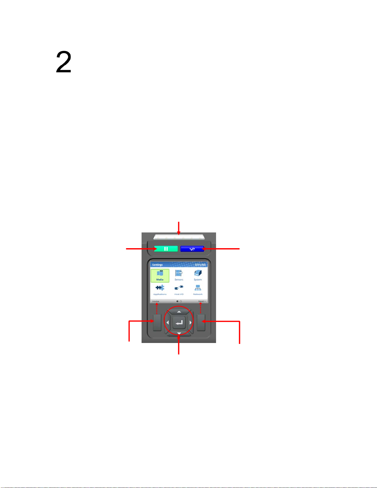
Control Panel
The control panel is located on the front of the printer and includes a Status LED array, QVGA color
display, PAUSE key, FEED key, LEFT SOFT key, RIGHT SOFT key, and navigation keys (buttons) with
the ENTER button in the center. These are described in the following
PAU S EKey FEEDKey
printe r, an initialization sequence will i m m e d i a t e l y appear on
tables.
Status LED
LEFTSOFTKey
The QVGA (quarter VGA) screen is a 320 x 240 pixel color display (non-touch). It is comprised of a
Header that shows the printer state and location with the User Interface (UI), the general display area,
and a footer used to show the purpose of the LEFT and RIGHT SOFT keys (when available).
The status LED indicates when the
•
LED is on solid: ONLINE and Ready to Print.
•
LED is off: OFFLINE and not accepting data.
•
LED is flashing: Fault Indicator.
Navigation/ENTER
printer is ONLINE, OFFLINE, or when there is a fault condition:
RIGHTSOFTKey
19
Page 20
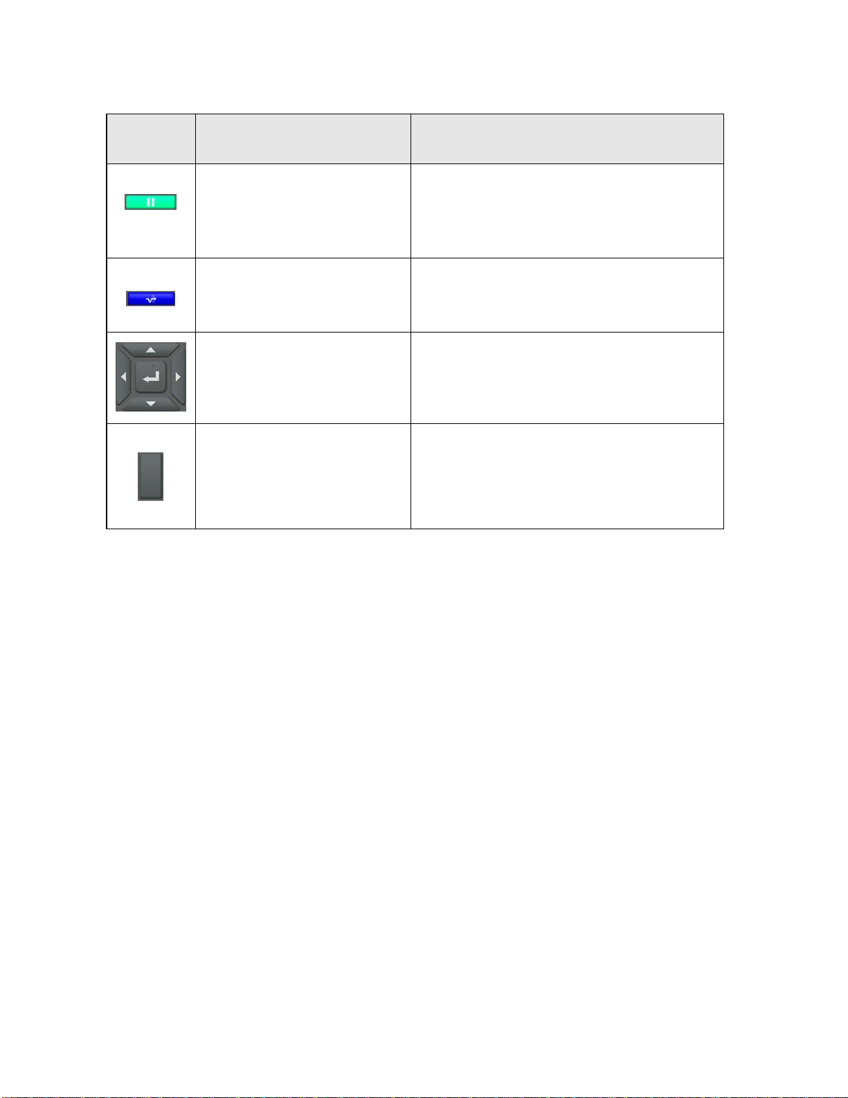
Button Description Functionality
PAUSE Key
Toggl e s the printer between
ONLINE and OFFLINE Modes.
FEED Key
Navigational Keys
The navigational menus consist
of up, down, left, and right keys
with a
ENTER button in the
center for selection.
Soft Keys
There is a LEFT and RIGHT
SOFT key on the sides of the
navigational menus. The labels
on the footer of the UI will explain their function.
When ONLINE, sets printer to OFFLINE
and the UI to the Home Screen.
When OFFLINE, returns the printer to the Home
Screen first and then a second press will put the
printer back ONLINE.
Advances the media
ONLINE, the menu Printer Control > Feed Key
Online must be enabled for this key to function.
Used to select icons, menu selection, and navigation in the UI.
Check the labels on the footer of the UI screen.
The meaning of the soft keys will vary.
Mode
one label length. When
Operating Modes
The current operating mode can be selected through the control panel keys or can result from routine
operations such as powering on the pri nt er .
Online: In ONLINE mode, the printer can receive and print data sent from the
key toggles the printer between the ONLINE and
Offline (Home): When the printer goes OFFLINE, the Status LED is off and the UI is in Home Screen. From the
Home Screen, the user has three different icons to choose from: 1) Wizard, 2) Settings, and 3) Calibration. The
green highlighted icon is the current selection. Pressing the PA US E key toggles the printer from
Screen to ONLINE mode.
Settings: When Settings is chosen from the Home Screen, the user has access to the printer menus by
navigating icons and traversing menu lists. Configurations can be saved using the Configs icon or by use of
the Auto-Save feature when returning ONLINE.
Wizard: When Wizard is chose n from the Home Screen, the user ca n perform different areas of printer setup
with the help of detailed explanations, references to online videos, and other material. On the first power-cycle,
the user will automatically be taken into the Printer Setup Wizard.
Fault: In fault mode, a fault condition exists that must be cleared before
LED indicator flashes, the alarm beeps
Before normal printing can continue, the fault must be corrected, the message
PAUSE k e y , and the printer placed ONINE.
(if configured to do so), and th e UI s h o w s t h e F a u l t s c r e e n .
OFFLINE modes. The Status LED indicator is on.
host. Pressing the PA U S E
Home
printing can continue. The Status
cleared by pressing the
20
Page 21
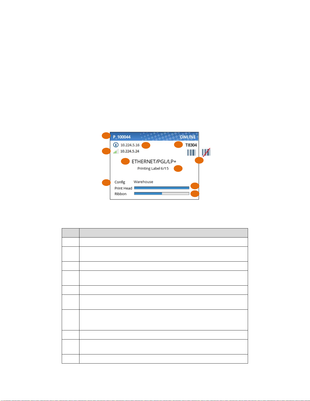
Online Screen
When the printer is ONLINE and ready to receive data, the ONLINE screen is shown. By default, this will
be the first screen the user sees after the power-up process has completed. In order to demonstrate the
full features of the ONLINE Screen, the following options are assumed:
• Network is installed and IP is set
• WiFi is installed and IP is set
• The printer has a Network Printer Name
• The Validator is installed and enabled
• The Active Configuration has been saved under a custom name “Warehouse”
• The Media > Handling > Print Mode is set to Transfer (ribbons).
• The menu option under System > Control > Batch Counter is enabled.
2
3
4
5
8
The illustration above has labels associated with each of the ONLINE screen features which are
described in the table below..
Item Description
The full model name includes the printer width and DPI.
1
The Network Printer Name can be set via telnet, SNMP, or the webpage
2
and is used with Ethernet or WLAN features.
The Ethernet IP address is displayed if the IP address is set (non-zero).
3
The WLAN IP address is displayed if the IP address is set (non-zero).
4
There is also a signal strength indicator next to the WLAN address.
The active IGP Emulation and the active Host IO (based on last job).
5
1
7
6
9
10
This area is reserved for messages such as receiving data, batch coun-
6
ters, and job status.
When the ODV option is enabled, the barcode icon will appear. If the op-
tion is installed but disabled, this icon will have a red strike. When validator
7
is not installed, no icon will show.
The last loaded configuration is referred to as the “Active Config”.
8
The print head gauge is used to show how much of the print head has
9
been used in relationship to the warranty.
The ribbon gauge is used when ribbons are installed (thermal transfer).
10
21
Page 22
If there is a warning that needs to be displayed while ONINE, a popup message will come onto the
screen. For example, entering Power-Saver mode, Print Head Hot, etc.
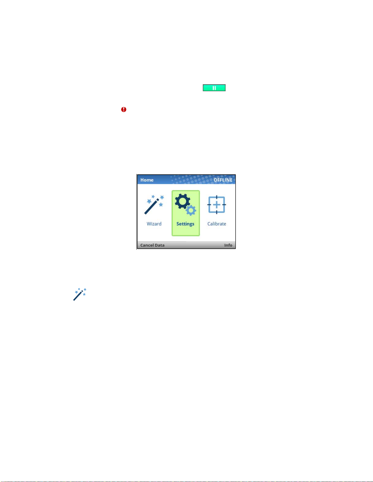
Offline (Home) Screen
When the printer is taken OFFLINE using the PAUSE Key , the UI will show the Home screen.
The Home screen will be the first screen seen by the user when transitioning from ONLINE to OFFLINE.
Likewise, it will be the last screen seen by the user before transitioning back ONLINE. The right corner of
the header may include the symbol in case there are faults in the system not yet cleared.
Using the navigational keys, the user can move among three options:
• Wizard – Provides Setup Instruction, Web Resources, and other links to the Printronix website
via QR barcodes for Product Support.
• Settings – Provides access to the printer menu system for configuration.
• Calibrate – Makes Calibration convenient and easy to perform when media or ribbon are
installed.
There are also functions for the LEFT and RIGHT SOFT keys. The LEFT SOFT key “Cancel Data” is
present if there is data within the buffer and the setting System > Control > Cancel Key is enabled. The
RIGHT SOFT key labeled “Info” will show the current configuration as text on the UI and the user can
scroll through the data and/or print if desired.
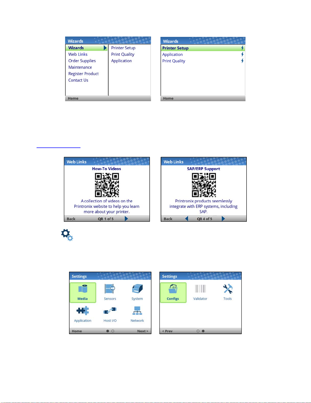
Wizard
The Wizard has several resources available as shown in the next figures. The greatest benefit of the
Wizard is the first subcategory “Wizards”. By highlighting this category (green) and pressing ENTER or
the RIGHT ARROW key, the user can then select the Wizard of choice to run:
• Printer Setup will help the user choose the proper display language, install ribbon & media,
set media and sensor options, calibrate, and run a test pattern to verify the product is working
properly.
• Application helps the user setup the menu configuration particular to their label or application
coming from the host system.
• Print Quality helps the user adjust the printer mechanically, and set Print Speed and Intensity
of the printer. A test printout helps the user in making the choices.
22
Page 23
When a Wizard has been completed (all steps executed until the end), the user is required to save their
configurations per usual procedure (see Saving a Configuration page 54). The exception to this is the first
time the printer is powered up; in this case, the user is automatically taken into the Printer Setup Wizard
and the configuration is automatically saved to Config 1 when completed.
The Wizard also has support available in the form of QR barcodes for the other categories such as “Web
Links”, “Order Supplies”, etc. These QR barcodes provide links to the Printronix website
www.printronix.com to view online videos, manuals, drivers, including places where they can order
supplies and register their product.
Settings
The Settings section of the menu represents the heart of the OFFLINE process in which users will peruse
the full menu set, edit menus, run diagnostics, and save configurations. The Settings section begins with
two pages of ICONs that can be selected using the navigational keys and the ENTER button.
When an ICON is selected, the user moves into the View Level in which their screen is divided with the
submenus on the left and the menus on the right. As they traverse the submenus using the up/down
arrow keys, the menus on the right change so that users can quickly see the menu contents.
23
Page 24
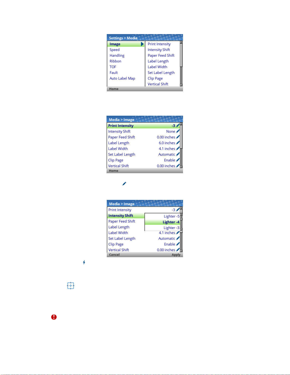
To view the full contents of a particular subsection or edit their menus, the user can either pr ess ENTER
or use the RIGHT ARROW key to get into the Edit Level. Conversely, the user can hit the LEFT ARROW
key to return to the previous screen.
When in the Edit Level, the user can scroll the menus and their values using the up/down arrow keys. The
user can edit any menu that has the icon by pressing the ENTER key, changing the value, and
confirming their change using the “Apply” soft key. There is also a “Cancel” soft key if the user does not
want to accept the change.
If the menu has a bolt icon, this is an executable menu and pressing the ENTER key will result in a
particular action (e.g., running a print test, clearing statistics). If the menu does not have any icon, then it
is a read-only menu and pressing ENTER key will not have any effect.
Calibration
Calibration must be performed whenever new media or ribbon is installed or any configuration parameter
that affects sensors is modified. Selecting this shortcut ICON and pressing the ENTER key will activate
the Auto-Calibrate function, also available in Sensors > Calibrate > Auto Calibrate.
Fault
When faults occur, the user will be notified with the following screen on the display. The red color is used
to make a clear indication that the printer needs attention.
24
Page 25
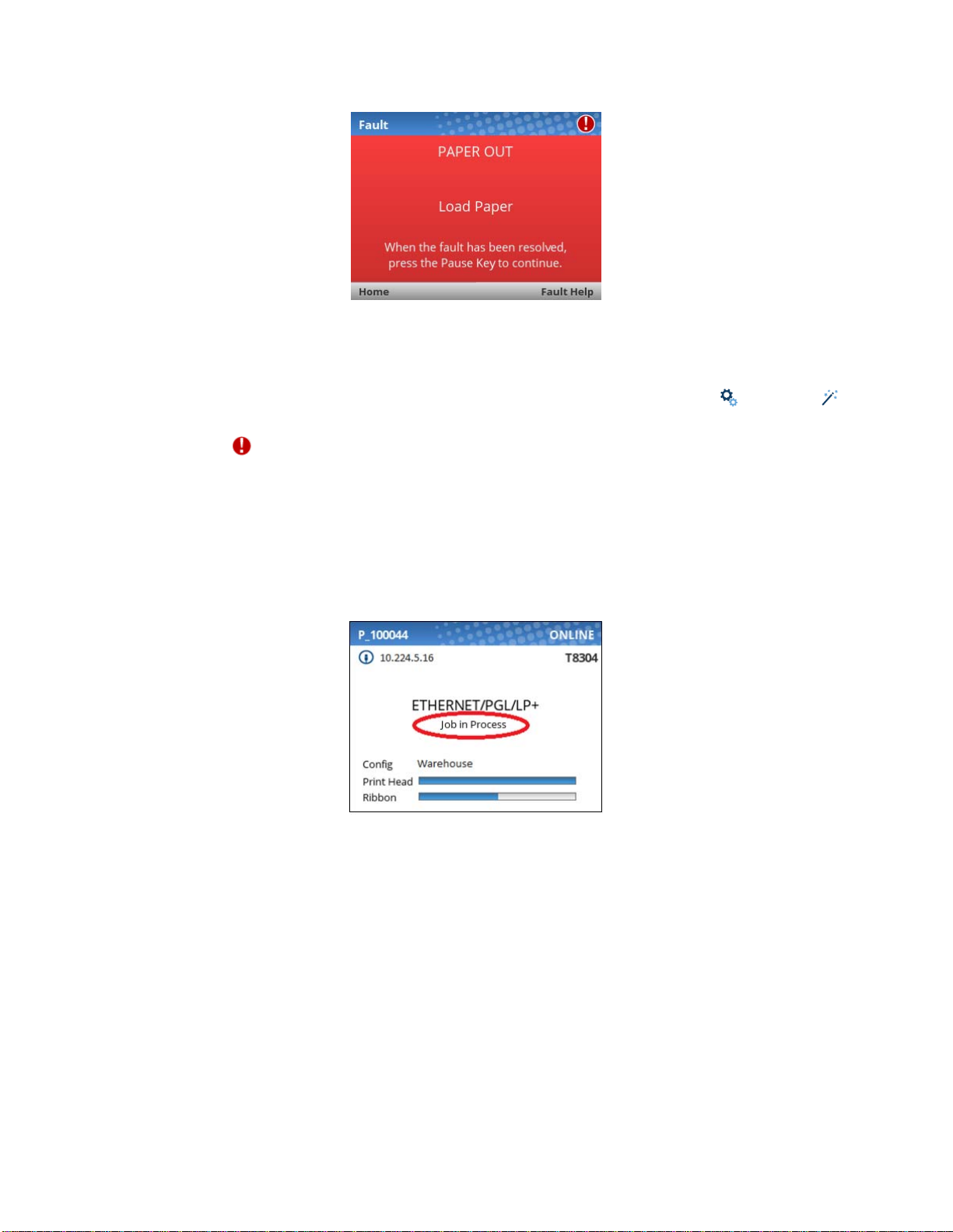
Users can follow the simple instructions shown in the screen or request additional help with the faults by
using the RIGHT SOFT key “Fault Help” if available. When Fault Help is selected, the user will be
provided a set of screens to help them through the process. However, Fault Help is only offered for faults
that are complex or require several steps with the printer mechanism.
The user can also choose via the LEFT SOFT key to go the “Home” screen, then to the Settings or
Wizard sections to adjust menu values (e.g., change media parameters, load Configs, etc.).
NOTE: The icon will be shown in the upper right corner as a reminder there is a fault that needs
to be cleared. Even when the user has completed all the steps necessary, the icon may
continue to be shown. Some faults are self-clearing in the OFFLINE state while other faults
are cleared only when returning ONLINE. If any fault was not successfully cleared, the Fault
screen shown above will reappear when the user attempts to return ONLINE.
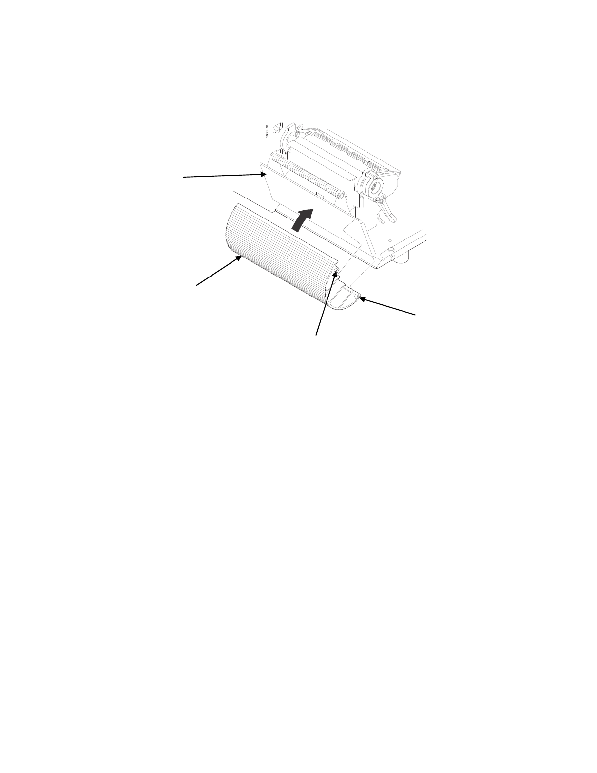
Job in Process
There is no dedicated LED or status indicator for Job in Process. Users will know the printer is receiving
data instead via messages in the circled portion of the ONLINE screen as shown below .
When the printer is in ONLINE mode and data is being received and being processed, the message “Job
in Process” will be shown in the message area. After the job has been printed the message will go away.
If the user is printing in batch mode and the option System > Control > Batch Counter is enabled, the
page count will have priority over the ‘Job in Process’ message.
When the printer is in OFFLINE mode and in the Home screen, the LEFT SOFT key will be labeled
“Cancel Data” if there is Data in Buffer when the printer is taken OFFLINE. If there is no Data in Buffer, then
the LEFT SOFT key label will not show anything. In order for the Cancel Data operation to be available, the
menu System > Control > Cancel Key must be enabled.
Media Handling Modes
Before you load media, you must decide which media handling mode to u se:
Continuous. Prints on the media and sends it out the front of the printer.
rewinder is installed, use “Continuous” f or Batch Rewind Mode page 26.
When the optional internal
25
Page 26

Tear-Off Strip. Prints on the media and sends it out the front until the
sitions the last label over the tear bar for
Tear-Off. After each label is printed, the printer positions the label over
to tear off the label before printing the nex t
will display to
Peel-Off. When the optional internal rewinder is installed, the prin ter
from the liner without user assistance. The
you to take
sage will display to remind you to remove the label
off information, see Label Peel-Off page 29.
Cut. When the optional media cutter is installed, the printer automatically
is printed or can cut the media after a
IGP Emulation cut
Once you have decided on the mode, configure the printer. See Chapter 3 page 52 for
remind you to remove the label before the next one can be printed.
away the label before printing the next one (on-demand printing ). A “Remove Label” mes-
command.
removal.
label (on-demand printing). A “Remove Label” message
label liner is wound on the rewinder. The printer waits for
before the next one can be printed. For Label Peel-
specified number of labels have been printed using the Active
print buffer is empty. It then po-
the tear bar and waits for you
prints and peels die-cut labels
cuts media after each label
more information.
Using th e Optional Internal Re w in de r
The printer can be set up to rewind labels after they have been printe d (Batch Rewind Mode) or to
automatically peel labels from their backing and dispense
(Peel-Off Mode). Both modes
field
unit option.
require an internal rewi nder, which is available as a factory installed or a
them one at a time while rewinding the liner
Batch Rewind Mode
Batch Rewind allows you to automatically rewind pri nted labels into a roll using the optional internal
rewinder.
Configuring the Printer Menu
1.
Set Media Handling to “Continuous” within the Application Wizard or directly in Media > Handling
> Media Handling menu.
2.
Press the PAUSE key to place the printer OFFLINE (Home Screen).
26
Page 27
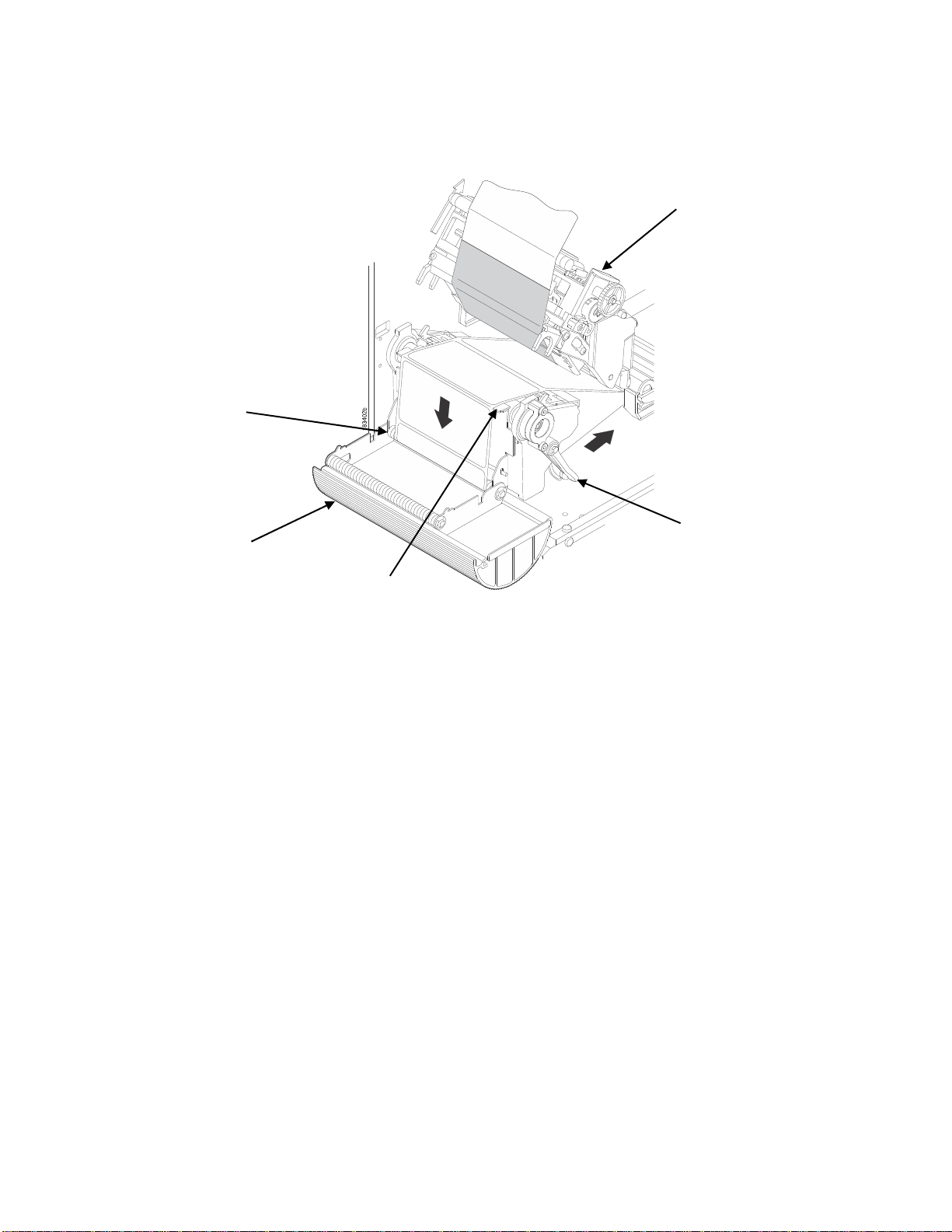
Installing the Paper Path
The paper path must be installed when using Batch Rewind mode.
To install the paper path:
Front Door
Paper
Path
Groove
Hook
1.
Open the front door by pulling it upwards, then forward.
2.
The bottom of the plastic paper path is shaped like a hook and the top has a groove:
a.
Hook the bottom of the paper path under the bottom edge of the front door
b.
Snap the groove on the paper path to the top edge of the front door
3.
Close the front door
27
Page 28
r
r
r
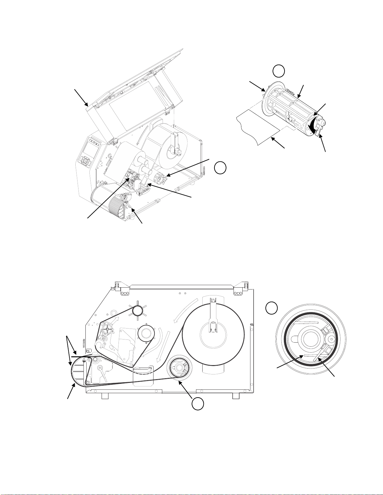
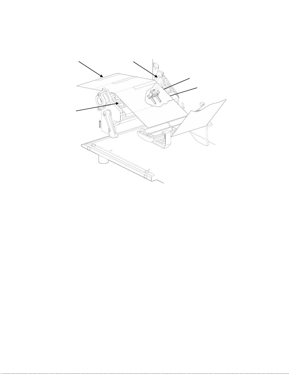
Loading Media
Media Cover
Printhead
Deck Lock Leve
Figure 1 Loading Media
Rewinde
A
Media Dampe
Guide
Back Flange
A
Raised Ridge
Slot
Media or
Liner
Rewinder
Release
Lever
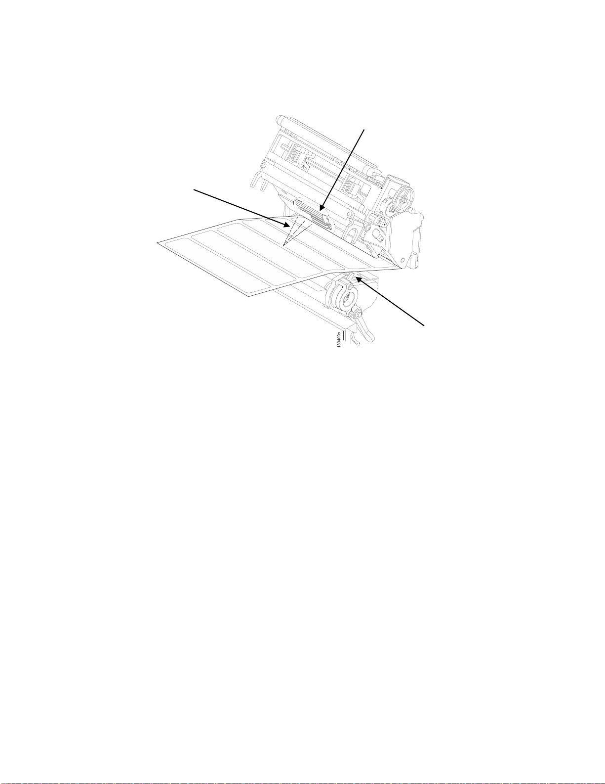
1. To load media, refer to Figure 2 and follow “Loading Media” steps 1 through 9 on page 29.
B
Media
Slot
Paper Path
B
Figure 2 Loading Media
Rewinder
Release Lever
28
Page 29

1. Thread the media over the front of the paper path and through the opening under the front door toward the internal rewinder
IMPORTANT If you do not complete the following step, it will be extremely difficult to
remove the printed labels from the rewinder.
2. Turn the release lever on the rewinde r counterclockwise and lock it i n place. This forms a raised
ridge along the width of the rewinder.
3. Insert the leading edge of the media into the closest slot of the rewinder, and slide the media
against the back flange.
4. Hold the media edge in the slot and manually rotate the rewinder one full
clockwise until the media is taut.
5. Press down on both sides of the pivoting deck and rotate the deck lock
against its stop to place the printhead assembly
6. Slide the Media Damper Guide, ref Figure 1 Loading Media page 28, to the outer edge of the
media.
7. Press the FEED key to advance the media to the next TOF (Top-of-Form)
8. Press the PAUSE key until “ONLINE” displays.
9. Close the media cover.
into the printing position.
revolution counter-
lever counterclockwise
position.
IMPORTANT The rewinder supports a maximum diameter of five inches of printed labels.
Exceeding this diameter can cause printed labels to rub on the bottom pan.
Removing Printed Media from the Rewinder
1.
Open the media cover, (ref Figure 1 Loading Media).
2.
Press the FEED key to advance the last printed label past the printhead, and tear the liner from behind the last printed label.
3.
Manually rewind the remaining printed labels onto the rewinder by turning the rewinder counterclockwise.
4.
Turn the release lever on the rewinder cl ockwise.
5.
Slide the roll of printed labels off the rewinder.
Label Peel-Off
Yo u can set up the printer to automatically peel die-cut labels off their line r (backing) and dispense them
one at a time while rewinding the line r.
Yo u can install the paper path to prevent long labels from accidentally
but it is normally not needed when using
page 27).
labels less than two inches long (see Installing the Paper Path
Configuring the Printer Menu
1 Set Media Handling to “Peel-Off” within the Application Wizard or directly in Media > Handling > Media
Handling menu.
2. Press the PAUSE key to place the printer OFFLINE (Home Screen).
Loading Media
1. If you want to install the paper path to print long labels, do so now by completing the steps listed in
Installing the Paper Path page 27.
adhering to the front door assembl y,
29
Page 30
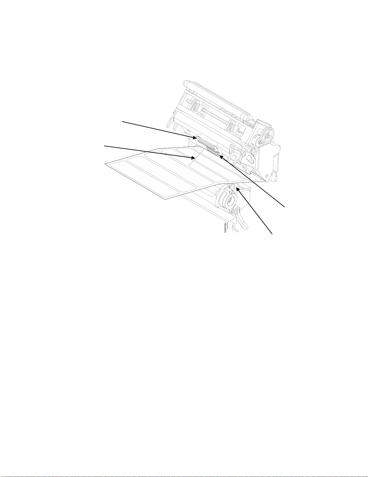
r
r
2. Open the media cover and refer to the Label Peel-Off illustration on the
instruction label on the inside of the cover.
Bottom Rolle
Paper Path
Ribbon and Media Loading
Pivoting
Deck
Deck Lock
Lever
Tear Ba
1. Open the front door by pulling it upward, then forward.
2. Open the pivoting deck by rotat ing the deck lo ck lever clockwise until the
3. Thread the media (label and liner) over the tear bar and around the
opening at the bottom of the front door and
into the printer.
deck swings upward.
bottom roller, then through the
IMPORTANT If you do not complete the following step, it will be difficult to remove the liner
from the rewinder.
3. Turn the release lever on the rewinder counterclockwise and lock it in
along the width of the rewinder.
4. Insert the leading edge of the media into the closest slot of the rewi nder,
the back flange.
5. Hold the media in the slot and rotate the rewinder one full revolution
is taut.
6. Remove labels from the liner so that behind the tear bar the liner is void of
and below the tear bar for about 2 inches.
7. Close the front door.
8. Complete the media routing as shown in Figure 2.
9. Press down on both sides of the pivoting deck and rotate the deck lock
10. Press the FEED key. The label advances to the peel-off position, and
LCD.
11. Manually remove the peeled label from the printer.
12. Press the PAUSE key until the ONLINE screen displays.
13. Close the media cover.
place. This forms a raised ridge
and slide the media against
counterclockwise until the media
labels for about 1.5 inches
lever fully counterclockwise.
“Remove Label” displays on the
30
Page 31

IMPORTANT The rewinder supports a maximum diameter of 5 inches of liner. Exceeding this
diameter can cause the liner to rub on the bottom pan. The rewinder is
designed to support the full amount of liner from a standard 8 inch diameter
media roll.
Removing Label Liner from the Rewinder
1. Open the media cover.
2. Open the front door.
3. Tear the liner at the tear bar.
4. Manually rewind the remaining liner onto the rewinder by turning the
rewinder counterclockwise.
5. Turn the release lever on the rewinder clockwise.
6. Slide the roll of label liner off the rewinder and discard.
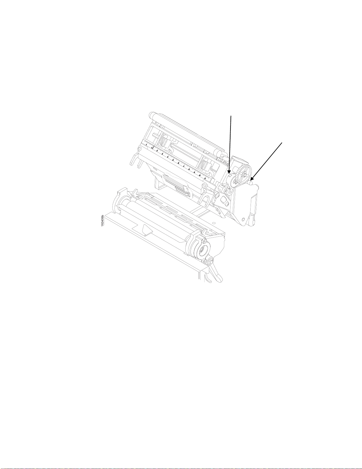
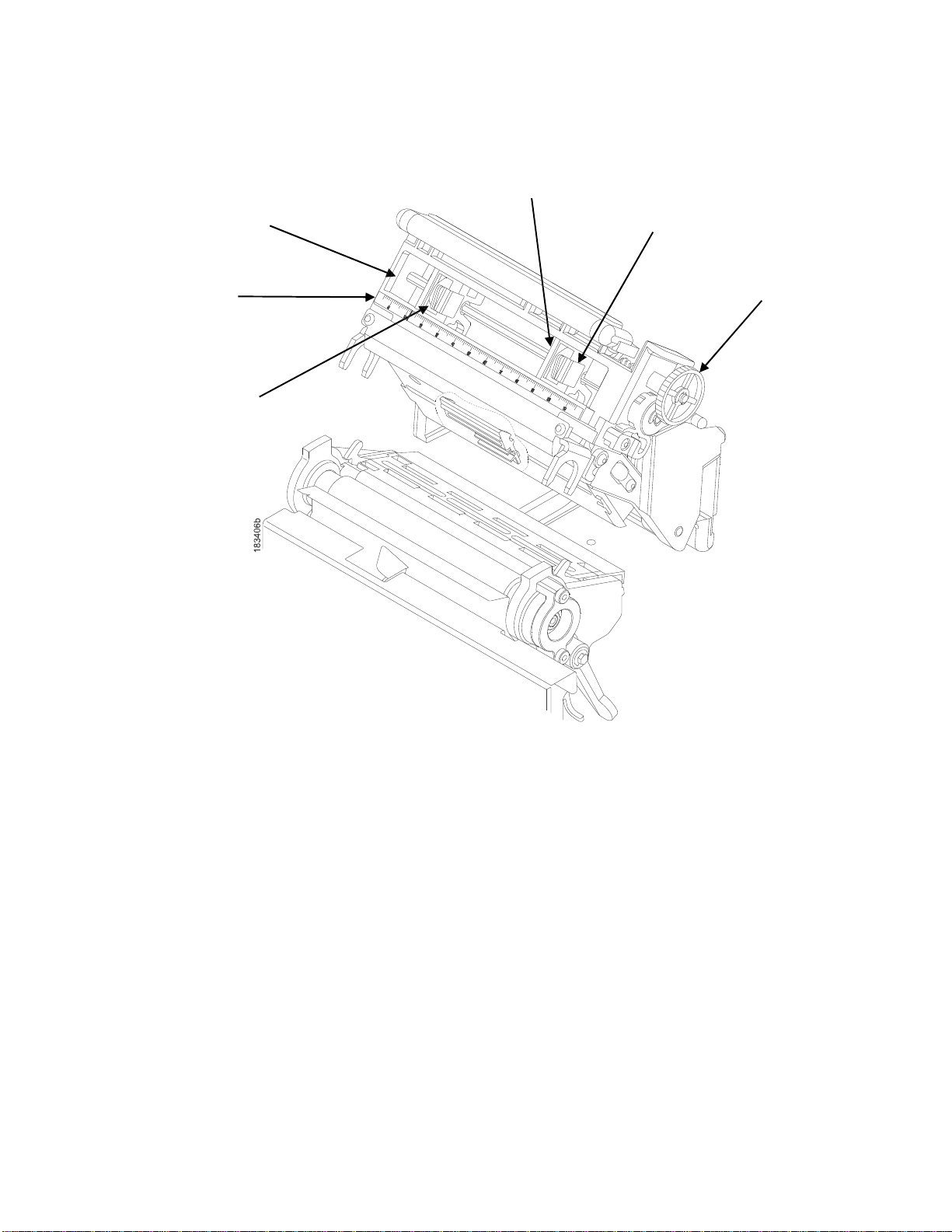
Removing the Paper Path
Remove the paper path from the front door when using Tear- O f f or T e a r - O f f Stri p media ha ndling, because
you will need to tear the label downward
against the tear bar.
Tear Bar
1. Open the front door by pulling it upward, then forward.
2. Grasp the upper right corner of the paper path and pry it off of the top of
3. After removing the paper path, close the front door.
Front Door
Paper
Path
Groove
the front door.
Hook
31
Page 32
A
Adj
4. Open the pivoting deck and load paper and ribbon normally.
Printing Adjustments
Printhead Pressure Adjustment
Sometimes you will need to adjust printhead pressure because of variations in media thickness and
width. The printhead pressure adjustment dial is shown above. The value shown at the bottom of the dial
is the active setting.
In general, adjust printhead pressure to the lowest value which produces the desired print quality. Die cut
labels usually require a setting of 4, while heavy stock requires a setting of 6 to max. The numbers on the
printhead pressure adjustment lever are relative only and do not indicate a specific printhead pressure or
media thickness. By following this procedure, you will minimize printhead wear.
ctive Pressure
Setting
Printhead Pressure
ustment Dial
32
Page 33
w
Printhead Pressure Block Adjustments
Left Pressure
Pressure Block
Adjustment Scale
Left Pressure
Block Handle
Block
Right Pressure Block
Right Pressure
Block Pointer
Lead Scre
Knob
Printhead pressure block adjustments are used to obtain a uniform print density across the width of the
installed media under a variety of media and ribbon conditions.
Left Pressure Block
Under normal printing conditions, the left block should be set with its handle aligned with the bold mark on
the pressure block adjustment scale. When
maximum
printing width, you may need to manually slide the left pressure block further to the left.
using media or ribbon widths less than one-third the printer’s
Right Pressure Block
The right pressure block should be positioned with i ts pointer (handl e on 4 inch printer models) near the
right edge of the media or ribbon in use. Turn
counterclockwise to
move it left.
Check the pressure block positioning by printing the Grey test pattern:
1. Press the PAUSE key to place the printer OFFLINE (Home Screen).
2. Go into the “Settings” section.
3. Select the “Grey” print test under Tools > Print Tests > Run Test.
the lead screw knob clockwise to move the block right or
33
Page 34
g
4. Press the
ENTER key to start the Grey test pattern. The pattern will start and continue to print.
5. Press
6. Check the test pattern. If necessary reposition the pressure blocks to
7. Whenever you reposition a pressure block, run the Grey test pattern to
ENTER again to stop printing.
across the media width. In most cases, only
obtain a uniform print density
the right pressure block may need to be adjusted.
verify the print pattern is
acceptable.
Positioning the Media Sensors
Your printer is equipped with upper and lower media sensors that detect the top-of-form position on
media with label length indicators (gaps, notches, holes, or black marks). These sensors also detect
when a Paper Out condition exists.
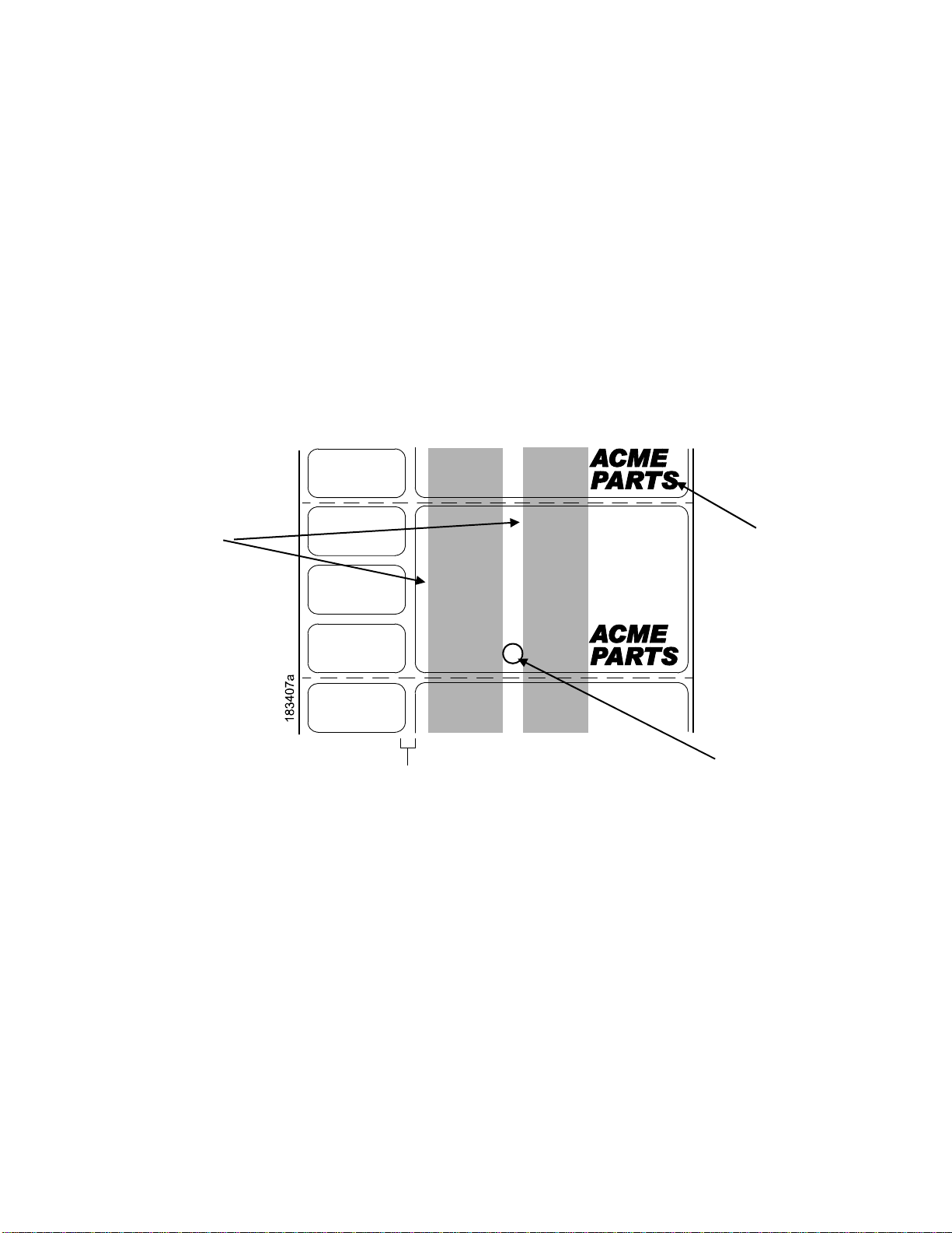
The media sensors should not be placed in the path of media features that could cause false gap
detection or paper out faults. Such features are dark pre-printing, rounded die-cut label corners, vertical
gaps associated with side-by-side labels, and extraneous cut-outs, as sho wn below.
Position the
media sensors
In either of the
grey shaded
areas.
Dark
Pre-printin
34
Extraneous
Cut-out
Vertical Gap and
Rounded Die-cut
Label Corners
Page 35
r
Sensing Media with Horizontal Black Mark(s) or Media with No Label Length
Indicators (Disable)
Black Mark
(underside
of media)
Media Guard
Opening
Visible Red Beam
from Lower Senso
Lower Sensor
Sensor Handle
Sensing Media with Horiz onta l Black Marks
Position the lower media sensor for detecting horizontal black ma rks located on the underside of media,
and position the upper sensor above the lower
1. Check the position of the sensor by looking through the long, narrow
the visible red light emitting from the
2. Use the sensor handle to manually position the sensor to the center of the
3. Select “Mark” in the Sensors > Control > Gap/Mark Sensor menu. See Sensing Different Media Types
page 39.
4. Perform an Auto Calibrate. See Running Auto Calibrate page 40.
sensor to provide a consistent background.
opening in the media guard. Use
lower sensor as a reference pointer.
black mark on the media.
Sensing Media with No Label Length Indi cato rs
1. When using media without label length indicators (no gaps, notches, holes, or marks) or when you
want to ignore all existing length indicators,
detect when a
2. Select “Disable” in the Sensors > Control > Gap/Mark Sensor menu. See Sensing Different Media
Types page 39.
3. Perform an Auto Calibrate. See Running Auto Calibrate page 40
Paper Out condition exists. Also set the upper sensor above it.
place the lower sensor in the center of the media so it can
35
Page 36
r
Sensing Media with Gaps, Notches, or Holes (Gap)
from Lower Senso
Visible Red Beam
Position the lower media sensor for detecting gaps, notches, or holes in
using direct thermal media, position the
upper sensor away from the lower senso r.
Upper Sensor
Media Guard
Opening
media with a white background. If
NOTE: The 4 inch T8000 media guard is divided into three open sensor areas. Make sure the media
sensor is placed in an open area.
1. Position the lower sensor directly under the center of the gap, notch, or
2. Check the position of the lower sensor by looking through the long,
guard. Use the visible red light emitting from
the lower sensor as a reference pointer.
3. Use the sensor handle to manually position the sensor to the center of the
media.
4. Select “Gap” in the Sensors > Control > Gap/Mark Sensor menu. See Sensing Different Media Types
page 39.
5. Perform an Auto Calibrate. See Running Auto Calibrate page 40.
hole.
narrow opening in the media
gap, notch, or hole in the
36
Page 37
r
r
r
Sensing Media with Dark Background Labels with Gaps (Advanced Gap)
Visible Red Beam
Lower Senso
Upper Senso
Upper Senso
Handle
Media Guard
Opening
NOTE: Ribbon is not displayed in this illustration. The upper and lower
sensors are designed to
function with or without ribbon installed.
The upper sensor and lower sensor are used together to detect liner gaps
a black or dark background on white or clear
liner.
1. Position the lower sensor directly under the center of the gap, and then
between die cut labels that have
place the upper sensor directly
over the lower sensor.
2. Check the position of the lower sensor by looking through the long,
guard. Use the visible red light emitting from
the lower sensor as a reference pointer.
3. Use the sensor handle to manually position the sensor to the center of the
the handle on the upper sensor to position it
directly above the lower sensor.
NOTE: When using ribbon, you may need to slide the ribbon to one side to
narrow opening in the media
gap in the media. Then use
adjust the upper sensor.
4. Select “Advanced Gap” in the Sensors > Control > Gap/Mark Sensor menu. See Sensing Different
Media Types page 39.
5. Perform an Auto Calibrate. See Running Auto Calibrate page 40.
37
Page 38

g
r
r
r
Sensing Dark Background Media with Notches or Holes (Advanced Notch)
Upper Senso
Upper Senso
Handle
Visible Red Beam
Lower Senso
Black line
on underside
of media
Media Guard
Openin
NOTE: Ribbon is not displayed in this illustration. The upper and lower
sensors are designed to
function with or without ribbon installed.
The upper sensor and lower sensor are used together to detect notches or
dark underside. This combination can be found
on the underside of
the label, interrupted by a notch or hole used as the label length indicator.
on tag stock that has a black vertical line along one edge
1. Position the lower sensor directly under the center of the notch or hole,
holes in media with a black or
and then place the upper
sensor directly over the lower sensor.
2. Check the position of the lower sensor by looking through the long,
guard. Use the visible red light emitting from
the lower sensor as a reference pointer.
3. Use the sensor handle to manually position the sensor to the center of the
Then use the handle on the upper sensor to
position it directly above the lower sensor.
NOTE: When using ribbon, you may need to slide the ribbon to one side to
narrow opening in the media
notch or hole in the media.
adjust the upper sensor.
4. Select “Advanced Notch” in the Sensors > Control > Gap/Mark Sensor menu. See Sensing Different
Media Types page 39.
5. Perform an Auto Calibrate. See Running Auto Calibrate page 40.
38
Page 39

Sensing Different Media Types
The printer’s media sensors can detect the different types of label length indicators on a large variety of
media types. This is accomplished by selecting
Advanced Notch, or
Wizard. Figure 21 on page 251 illustrates the different media types and label length indicators used
1. Press the PAUSE key to place the printer OFFLINE (Home Screen).
2. Find the Settings ICON and press ENTER.
3. Press the UP + DOWN ARROW keys together until “ENTER SWITCH UNLOCKED” displays.
4. Find the Sensors ICON and press ENTER.
5. Select the “Control” submenu and press ENTER.
6. Find the “Gap/Mark Sensor” option and press ENTER to edit this menu. Find the option that matches
the type of label length indicators on the installed media displays:
Disable under Sen s o r s > C on t r o l > Gap/Mark Sensor menu or within the “Printer Setup”
the correct sensor option: Gap, Mark, Advanced Gap,
on them.
• Mark. Select when using media that has horizontal black marks
the label liner or tag stock.
• Gap. Select when using media with a liner space bet ween die-cut
stock with notches or holes as label length
indicators on white background media.
• Advanced Gap. Select when using media that has liner gaps
background.
• Advanced Notch. Select when using media with notches or holes
vertical line on the underside of the media.
• Disable. Select when using media with no label length indicators (no
black marks) or when you want the printer to
installed media.
ignore all existing label length indicators on the
NOTE: When you select Disable, the length of each label is based on the
Length menu or the value
sent via host software.
NOTE: If the printer detects a false PAPER OUT message when you change
Advanced Notch to Gap or Mark sensing or
Calibrate
7. Press ENTER to enable the displayed option or use the RIGHT SOFT key labeled “Apply”. An
.
asterisk (*) appears next to the selection
8. Press the PAUSE key or the LEFT SOFT key labeled “Home” to return to the Home Screen.
9. Review Calibrating the Media Sensors page 39.
10. Perform the Auto Calibrate procedure per Running Auto Calibrate page 40.
vice-versa, find the Home Screen and run
located on the underside of
labels or when using tag
between die cut labels with black
that interrupt a black
gaps, notches, holes, or
Media > Image > Label
from Advanced Gap or
Calibrating the Media Sensors
Due to manufacturing differences in media and ribbon, the media sensors may have difficulty
differentiating between the label and the liner or the label
printer may intermittently skip a
“PAPER OUT”.
Media sensor sensitivity and reliability can be improved by changing the
Thresh and/or Sensors > Control > Paper Out Thresh values. You can change
automatically by performing an Auto Calibrate or Manual
Calibrate me nu section. (The change s take effect immediately within the current configuration menu.)
label or display a fault message such as “GAP NOT DETECTED” or
and the black mark. When this occurs, the
Sensors > Control > Gap/Mark
these values manually or
Calibrate procedure from the Sensors >
39
Page 40

Auto or Manual Calibrate is completed successfully when the displayed
matches that of the installed media. When
from the
is selected, the Sensed Distance should match the length
leading edge of the next black
When you have completed Auto or Manual Calibrate, you can verify the new
pressing the FEED key several times. Each time you
the correct Top-of-Form
Once you confirm the correct values, save them to the desired configuration
printe r. See Saving a Configuration page 54.
trailing edge of one gap to the trailing edge of the next gap (or one label + one gap). When Mark
mark.
position of the next label.
Gap is selected, the Sensed Distance should match the length
from the leading edge of one black mark to the
press FEED, media advances one label and stops at
Sensed Distance value correctly
values are correct by
menu before powering off the
Running Auto Calibrate
Yo u can initiate Auto Calibrate via the Home Screen I CO N or via the Senso rs menus within the
Settings section.
NOTE: Verify that the Gap/Mark Sensor option (Gap, Mark, Advanced Gap,
Disable) matches the installed media. See Sensing Different Media Types page 39.
Check that the media sensors are horizontally positioned to permit
indicators. See Positioning the Media Sensors page 34.
Make sure the Media > Image > Label Length value matches the physical length of the installed
media. Entering the
calibrate for long labels (so actual gaps, notches, and marks can be detected) and reduce the
amount of media advanced for short labels.
correct length forces the printer to advance media far enough during
Advanced Notch, or
sensing of the label length
If you try to do an Auto Calibrate when Peel-Off Media Handling is
display “CANNOT CALIBRATE” error. Before you can do an Auto Calibrate, you must select
another
1. Press the PAUSE key to place the printer OFFLINE (Home Screen).
2. Select the Calibrate ICON and press the ENTER key.
3. Media advances until it can accurately detect the label length
Form position. The Sensed
4. Auto Calibrate is successful when the Sensed Distance value correctly
media:
• Gap/Mark Sensor = Gap, Advanced Gap, or Advanced Notch :
is the physical length of one label plus
• Gap/Mark Sensor = Mark: The Sensed Distance value is the
leading edge of one black mark to the
• Gap/Mark Sensor = Disable: Not applicable. If Gap/Mark Sensor is
Distance value will not be updated.
If “GAP NOT DETECTED” displays, run Auto Calibrate again.
If Auto Calibrate continues to end with an incorrect Sensed Distance
message displayed, run Running Manual Calibrate as
page 234.
media handling mode.
Distance value will then display for one second.
indicators and then stops at the Top-of-
matches that of the installed
The Sensed Distance value
the length of one gap, notch, or hole.
physical distance from the
leading edge of the next.
value displayed or a fault
described on page 46 or see Table 12 on
NOTE: The amount of media sampled during Auto Calibrate is based on the
transitions detected, without error, between a
5. Press the FEED key several times. Each time you press FEED, the media
and stops.
label and its label length indicators.
advances one label length
enabled, the LCD will
set to Disable, the Sensed
length of a label and
40
Page 41

NOTE: After a form feed, the position of the leading edge of the next label
Media Handling mode selected under Media > Handling > Medi a Handling menu. Tear-Off
and Tear-Off Strip Media Handling
Continuous will
6. Once the Sensed Distance value is confirmed, you will need to save it to
menu before powering off the printer. See Saving a Configuration page 54.
7. Press the PAUSE key until the printer returns ONLINE.
position the label edge under the printhead.
will position the label edge at the tear bar, while
depends on the type of
the desired configuration
Running Media Profile
The Media Profile printout shows the relationship of the Paper Out Threshold and the Gap/Mark
Threshold values, illustrates if and when each label length
between the label length
you set the thresholds for difficult media. This includes pre-printed labels and labels with poor gap/media
dynamic range.
Once Media Profile is initiated, the printer will continue to advance media and print the profile in
landscape orientation until you press ENTER to stop printing.
indicators and the label. The profile printout (see Figure 3 on page 42) helps
NOTE: Verify the Sensors > Control > Gap/Mark Sensor option (Gap,
Advanced Notch, or Disable) matches the
Types page 39.
You will need a minimum installed label width of two inches to support
Ensure the media sensors are horizontally positioned to permit
indicators. See Positioning the Media Sensors page 34.
Ensure the Media > Handling > Print Mode option matches the media installed. Select “Direct”
for heat sensitive media
required).
1. Press the PAUSE key to place the printer OFFLINE (Home Screen).
(no ribbon required) or “Transfer” for the rmal transfer media (ribbo n
indicator is detected, and shows the difference
Mark, Advanced Gap,
installed media. See Sensing Different Media
the Profile printout.
sensing of the label length
2. Find the Settings ICON and press ENTER.
3. Press the up and down arrow keys together until “ENTER SWITCH UNLOCKED” displays.
4. Find the Sensors ICON and press ENTER.
5. Select the “Diagnostic” submenu and press ENTER.
6. Find “Media Profile/Profile Print” and then press ENTER to start the profile printing process.
The printer will advance media and continue to print a dynamic profile image dep icting the
relationship of the label and any label length indicators detected.
7. Press
8. Press the PAUSE key to place the printer OFFLINE (Home Screen).
ENTER to stop the profile printing.
NOTE: The Gap/Mark and Paper Out Threshold values shown on the Profile printout represent the
last values determined from a successful Auto or Manual Calibrate or the factory default
values if no Auto or Manual Calibrate was performed.
41
Page 42

1023
0767
Paper Out (578)
0511
Gap Mark (421)
0255
0000
1023
0767
Figure 3 Media Profile Printout
Gap Sensing
This figure shows a Media Profile printout of a smart label where Ga p/Mark Sensor is set to Gap in the
Sensors > Control menu.
In this example, the gap threshold value the printer selected (represented by
too close to the amplitude of the antenna pul se.
This may cause the printer to falsely use the antenna as
the gap (top-of-form).
the Gap/Mark dotted line) is
42
Page 43

Media Sensor
Position
1023
0767
0511
Paper Out (441)
0255
Gap (209)
0000
Indicates Type of Gap/Mark
Sensing Selected
Detected Amplitude
of the Antenna
Detected Amplitude
of the Gap
43
Page 44

To avoid this problem, increase the Threshold Range value to 60% or 70% in the Sensors > Control >
Gap/Mark Thresh menu (the default is 50%), then run a Running Auto Calibrate again, page 40.
Any changes to Threshold Range will not take effect until you run an
This will raise the Gap/Mark threshold high enough so that the printer will not
the gap (top-of-form).
Media Sensor
Position
Auto Calibrate again.
falsely use the antenna as
1023
Paper Out (441)
0767
0511
Gap (289)
0255
0000
Indicates Type of Gap/Mark
Sensing Selected
Detected Amplitude
of the Antenna
Detected Amplitude
of the Gap
44
Page 45

)
Advanced Gap Sensing
This figure shows a Media Profile printout of a smart label where Se nsors > Control > Gap/Mark Sensor
menu is set to Advanced Gap.
In this example, the gap threshold value the printer selected (represented by
too close to the baseline (die cut label). If there is
the printer may
falsely use the noise as the gap (top-of-form).
an increase in noise or the opacity of the liner or rib bon,
the Gap/Mark dotted line) is
Media Sensor
Position
1023
0767
Paper Out (301)
Adv. Gap (120)
Indicates Type of Gap/Mark
Sensing Selected
To avoid this problem, increase the Threshold Range value to 60% in the
Thresh menu (the default is 50%), then run an Auto Calibrate
0511
0255
0000
Baseline (die cut label
Detected Amplitude
Detected Amplitude
of the Antenna
Sensors > Control > Gap/Mark
again (Cross-ref to Auto Calibrate).
of the Gap
NOTE: Any changes to Threshold Range will not take effect until you run an
This will raise the Gap/Mark threshold high enough so that the printer will not
noise as the gap (top-of-form).
falsely use the antenna or
Auto Calibrate again.
45
Page 46

Paper Out (301)
Gap (160)
Indicates Type of Gap/Mark
Sensing Selected
Media Sensor
Position
1023
0767
0511
0255
0000
Detected Amplitude
of the Antenna
Detected Amplitude
of the Gap
Running Manual Calibrate
Manual Calibrate should be performed only when the values derived from Auto Calibrate fail to improve
the media sensors’ ability to sense label length
located in the Sensors > Diagnostics section.
NOTE: Verify the Gap/Mark Sensor option (Gap, Mark, Advanced Gap,
matches the installed media. See Sensing Different Media Types page 39.
Ensure the media sensors are horizontally positioned to permit
indicators. See Positioning the Media Sensors page 34.
Ensure the Media > Handling > Print Mode option matches the media installed. Select “Direct”
for heat sensitive media
required).
If you try to do a Manual Calibrate when Peel-Off Media Handling is
display a “CANNOT CALIBRATE” er r o r . Before you can do a Manual Calibrate, you must
select another
1. Press the PAUSE key to place the printer OFFLINE (Home Screen).
2. Find the Settings ICON and press ENTER.
3. Press the up and down arrow keys together until “ENTER SWITCH UNLOCKED” displays.
4. Find the Sensors ICON and press ENTER.
5. Select the “Diagnostics” submenu and press
6. Find “Manual Calibrate” and then press
7. Follow the instructions displayed on the LCD. Example: “REMOVE RBN&MEDIA/Press Enter”
indicates that you must open the pivoting deck and remove the ribbon and media from under the
printhead, close and lock the pivoting deck, and press the
media handling mode.
(no ribbon required) or “Transfer” for the rmal transfer media (ribbo n
indicators on the installed media. Manual Calibrate is
Advanced Notch, or Disable)
sensing of the label length
enabled, the LCD will
ENTER.
ENTER to start the process.
ENTER key.
46
Page 47

8. During the last step of Manual Calibrate, the printer will advance the
label length indicators and stop at the
display for
that of the installed media. If “CALIBRATION FAIL” error displays, run Manual Calibrate again.
one second. The calibrate is successful when the Sensed Distance value correctly matches
Top-of-Form position. The Sensed Distance value will then
NOTE: The amount of media sampled during Manual Calibrate is based on
the transitions detected without error,
9. Press the PAUSE key to place the printer OFFLINE (Home Screen).
10. Press the FEED key several times. Each time you press FEED, the med ia
and stops.
between a label and its label length indicators.
NOTE: After a form feed, the position of the leading edge of the next label
Media Handling mode selected via Media > Handling > Media Handling. Tear-Off and TearOff Strip Media Handling
the label edge under the printhead.
11. Once the correct values are confirmed, save them to the desired
off the printer. See Saving a Configuration page 54.
positions the label edge at the tear bar, while Continuous positions
media and attempt to detect the
the length of a label and
advances one label length
depends on the type of
configuration menu before powering
Cleaning
Depending on the media used, the printer may accumulate residues (media dust, adhesives, etc.) as a
by-product of normal printing. T o maintain top
cleaning the printer
periodically.
WARNING Set the printer power switch to O (Off) prior to performing any cleaning
Leave the power cord connected to keep the printer grounded
the risk of electrostatic damage.
printing qua lit y, you should remove these resid ues by
and to reduce
tasks.
IMPORTANT When the printer is powered Off, menu settings that were changed and not
saved an any print data remaining in the print buffer will be lost. To prevent the
loss of recent menu changes, see Saving a Configuration page 54
.
CAUTION • Do not wear rings or other metallic objects while cleaning any interior area of
the printer.
• Use only the cleaning agents recommended in this section. Use of
cleaners may damage the printer and void its warranty.
• Do not spray or drip liquid cleaning solutions directly into the
the solution on a clean lint-free cloth and then apply
printer.
the dampened cloth to the
• Do not use canned air in the interior of the printer as it can blow dust
onto sensors and other critical components.
• Only use a vacuum cleaner with a nozzle and hose that are
grounded to drain off static build up.
conductive and
• All reference in these procedures for use of isopropyl alcohol
99% or greater isopropyl alcohol content be used to
moisture corrosion to the printhead.
reduce the risk of
other
printer. Apply
and debris
requires that a
Exterior Cleaning
Clean the exterior surfaces with a clean, lint-free cloth. If ne ces sa ry , use a mild detergent or desktop
cleaning solution.
47
Page 48

Interior Cleaning
Clean the interior of the printer by removing any dirt and lint with a v acuum cleaner, as described above,
or use a brush with soft non-metallic bristles.
Cleaning the Printhead, Platen Roller, Media Sensors and Media Damper
NOTE: Even though the printhead, platen roller, media sensors and media
listed in these cleaning procedures, debris
travel to the
printhead is cleaned and in the order shown.
printhead area and therefore should be cleaned and examined e ach time the
and adhesive on these components can ultimately
damper are individually
Printhead Cleaning
As you use your print er, the printhead may beco me dirty with ribbon re sidue and label adhesives which
can result in poor print qual it y. Keeping the
Cleaning Agent - Clean the printhead using a Printhead Cleaning Pen,
an Isopropyl Alcohol Wipe, Printronix PN
Schedule - Clean the printhead each time you install a new roll of ribbon
mode) or when you install a new roll or box of
WARNING If you have just been printing, allo w one minute for the printhead to cool
to avoid burns from accidental printhead contact.
printhead clean will help maintain its life.
Printronix PN 203502-002 or
254945-901.
(thermal transfer print
media (direct thermal print mode).
down
CAUTION • Avoid electrostatic damage to the printhead by first making hand contact with
an unpainted part of the printer frame or by using an anti-static wrist strap
grounded to the printer frame.
• Do not use hard, sharp or abrasive objects to remove residue from the
printhead.
• Do not touch the heating element surface of the printhead with your hands to
avoid printhead corrosion. Any accidental skin contact with the element
surface should be immediately followed by a thorough cleaning with a
Printhead Cleaning Pen or an Isopropyl Alcohol Wipe.
• The heating element surface should be free from any condensation to avoid
corrosion.
1. Rotate the blue deck lock lever clockwise to open the pivoting deck and remove the media and
ribbon, if installed.
2. Clean the printhead by gently rubbing an Isopropyl Alcohol Wipe or the felt tip of a Printhead Cleaning
Pen across the printheads light brown heating elements area. Allow the printhead to dry for one
minute before reloading ribbon or media.
NOTE: Even after a thorough cleaning with a Printhead Cleaning Pen or
see printouts with voids or streaks. This
hard to remove
Cleaning Card or Sheet. When using a cleaning card or sheet,
packaging. Thermal printer cleaning cards and sheets are available on the internet.
when normal cleaning cycles are not maintained. Try using a Thermal Printer
may be the result of baked-on ribbon resin that can be
Alcohol Wipe, you may still
follow the directions on the
Platen Roller Cleaning
Label parts, media dust, and adhesive residue on the platen can degrade print quality and cause voids in
your label image.
48
Page 49

r
)
r
r
r
Cleaning Agent - Use an isopropyl alcohol wipe or small amount of
isopropyl alcohol on a clean cloth
to clean the platen roller.
Schedule - Clean the platen roller each t ime you clean the printhead .
3. Clean the platen roller by first removing any label parts from its surface by
isopropyl alcohol wipe or clean cloth moistene d with
dust, debris, or label
adhesive. The platen roller can be rotated forward by hand to access and clean
isopropyl alcohol to remove any remaining paper
its entire surface area.
hand. Then use an
NOTE:
Even though power is removed from the platen motor, some drag will be felt as you rotate the
platen.
4. Check the platen roller for razor cuts, nicks, and gouges that may cause
This type of damage usually requires platen
roller replacement.
voids in the printed image.
Media Sensor Cleaning
The upper and lower media sensors should be clean ed to ensure reliable Top of Form and Paper Out
sensing.
CAUTION
Do not use isopropyl alcohol, solvents, or abrasive agents to clean the lower
media sensor as they can damage the sensors lens cover.
Cleaning Agent - Use a brush with soft non-metallic bristles or a vacuum cleaner, described above, to
remove paper dust.
NOTE:
An Isopropyl Alcohol Wipe or Printhead Cleaning Pen can be used to remove label adhesive
from the upper sensor.
Schedule - Clean the media sensors ea ch time you clean the printhead.
5. Brush away or vacuum any dust or debris from the upper and lower
sensor.
Pivoting
Deck
Printhead
Heating
Elements
A
Peel/Tear Doo
Lower Media
Senso
(visible with
Red LED
Printhead Cover/
Upper Media Senso
Deck Lock
Lever
Platen Rolle
49
Page 50
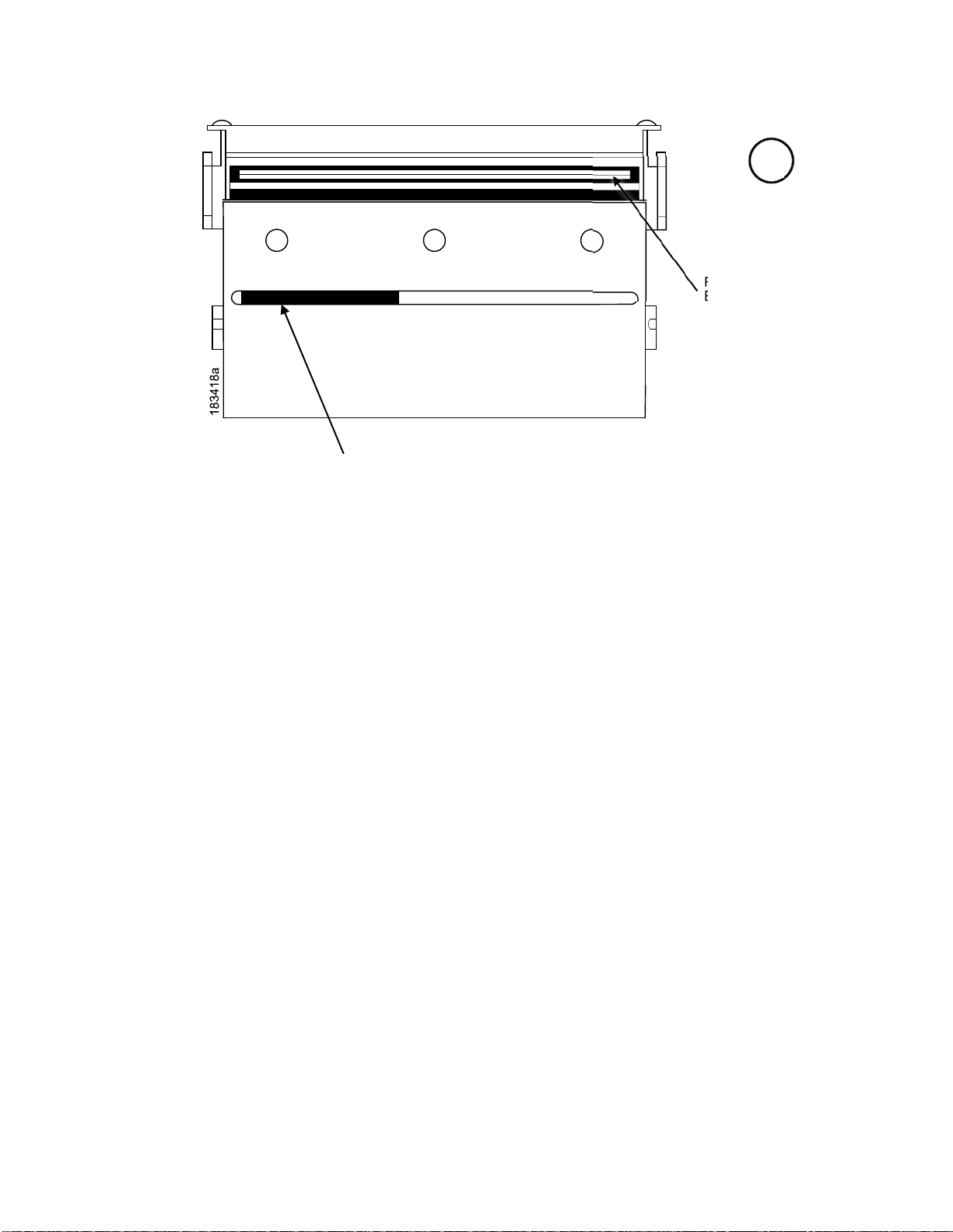
r
Print
Element
Upper
Senso
A
Media Damper Cleaning
The media damper and its media width guides (see Media Sensor Cleaning page 49) can accumulate
parts of labels, adhesive and paper dust residue that can prevent the proper guiding of labels.
Cleaning Agent - Use an isopropyl alcohol wipe or i sopropyl alcohol on a
Schedule - Clean the media damper and its width guides each time you
6. Clean the media damper by rotating it counterclockwise and remove any
surface. Then use an isopropyl alcohol wipe or
all remaining
IMPORTANT
debris and adhesive from the damper and its inboard and outboard guides.
All adhesive must be completely removed to prevent future die cut labels from
being accidently peeled away from their liner.
clean cloth moistened with isopropyl alcohol to remove
clean cloth.
clean the printhead.
label parts from its bottom
Cutter Option Cleaning
The cutter requires only periodic cleaning.
WARNING
Perform the following procedure whenever too much dust or debris is visible.
1. Set the printer power switch to O (Off).
2. Rotate the deck lock lever fully clockwise until the deck swings upward.
3. Remove the cutter top cover by loosening the two captive thumbscrews.
4. Place the cutter in the down (open) position.
Keep your fingers away from the cutter blades. They are sharp.
50
Page 51

5. Use a vacuum or can of compressed air with a nozzle around the area of
any dust or debris.
6. Use a cloth with a light amount of WD-40 oil to clean adhesive from the
lower stainless steel cutter guides. Adhesive oil
cloth to prevent
dust attraction.
must be cleaned from the blade and guides with a dry
the cutter blade to remove
cutter blade and upper or
CAUTION Do not use isopropyl alcohol to clean the cutter blade – it dissolves oils
required for lubrication.
7. Place the cutter in the up (closed) position.
8. Install the cutter top cover and tighten the two captive thumbscrews.
9. Properly route the media through the printer and cutter.
10. Close the pivoting deck and rotate the deck lock lever fully
11. Set the printer power switch to | (On).
12. Test the printer cutting operation by running a test print within the Tools > P rint Tests > Run Test
menu.
counterclockwise.
51
Page 52
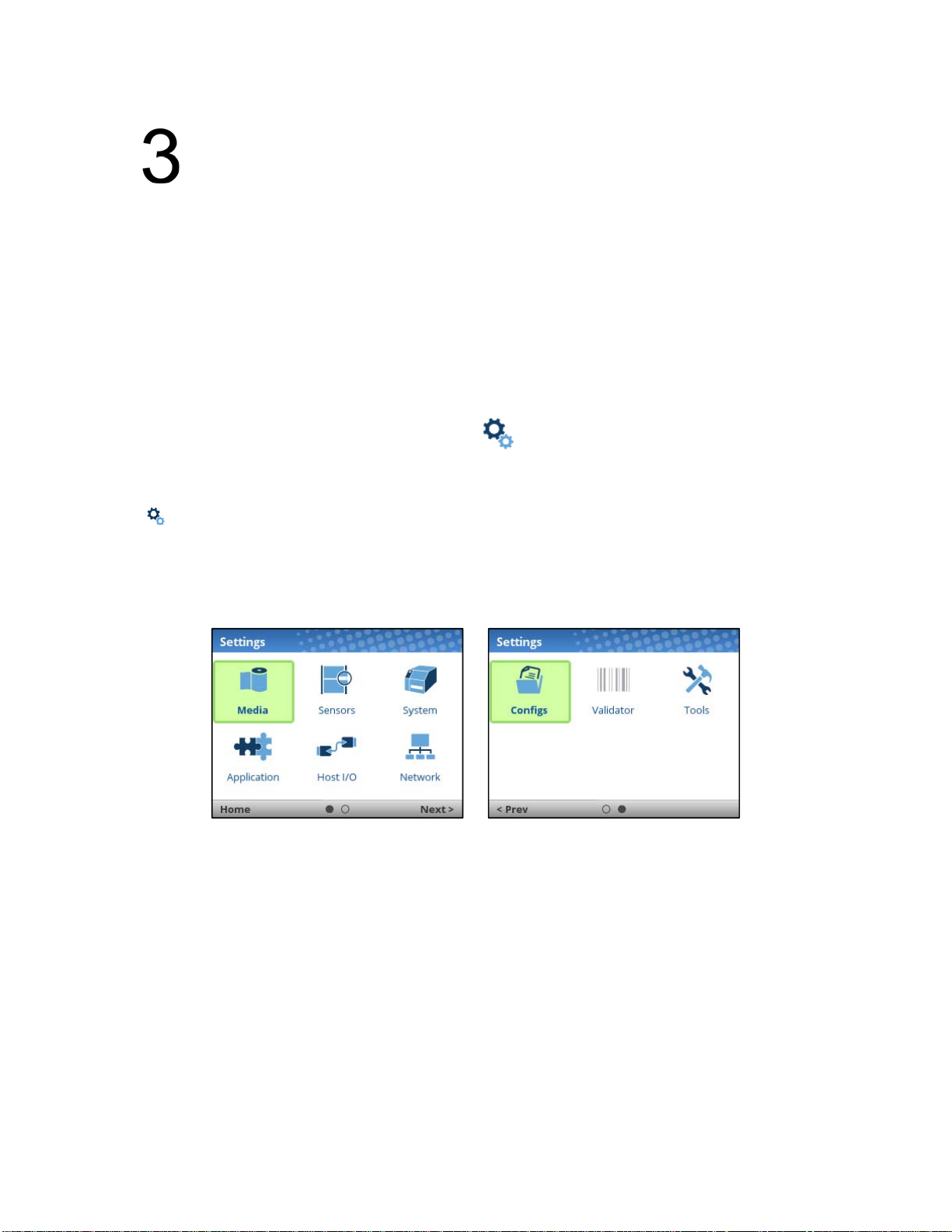
Configurations
Overview
This chapter provides information about:
Setting, saving, modifying, and printing configurations
Structure of the configuration
Menu and Configuration Parameters
Setting Printer Configuration Parameters
Configuration parameters are set from the control panel and stored into the printer’s fla s h memory. The
parameters define how the printer will respond to
The Settings section is where the complete set of menus or configuration parameters are located.
The T8000 menu system is three levels deep and consists of the ICON Level, View Level, and Edit Level.
The ICON Level. The top level of the menu system is known as the ICON Level and consists of two
screens as shown below. The green shading shows the current icon selected. The arro w keys are used to
select different icons (and even move between screens).
command and interface signals from the host comput er.
IMPORTANT
When the right icon is highlighted, the user must press
The View Level. The 2nd level of the menu system is known as the View Level and is separated into a
left and right side. On the left side are submenus, and on the right are the actual menus or configuration
parameters. The up/down arrow keys will move to different submenus (highlighted in green) a nd the right
side will show a preview of the configuration parameters available for that submenu.
52
The VALIDATOR icon is in grey to symbolize that the ODV option is not installed.
When in grey, an icon cannot be selected.
ENTER to move into the View Level.
Page 53

When the right submenu is highlighted, the user can press
into the Edit Level. Likewise, the user can use the left arrow key to move back to the ICON Level.
The Edit Level. The last level of the menu system is known as the Edit Level and contains all the
configuration parameters for a given submenu. The user can scroll through the menus using the up/do wn
arrow keys to view the current configuration values.
ENTER or the RIGHT ARROW key to move
For menus that have the edit icon , the user can modify the value by pressing the
enter Edit Mode. If the menu has a bolt icon, this is an executable menu and pressing the ENTER key
will result in a particular action (e.g., running a print test, clearing statistics). If the menu does not have
any icon, then it is a read-only menu and pressing ENTER key will not have any effect.
ENTER key to
IMPORTANT When entering the Edit Mode, a message “ENTER SWITCH LOCKED” may ap-
pear. In this case, the user will not be allowed to enter Edit Mode until the panel
is unlocked. To unlock the configuration, press the UP+DOWN arrow keys simultaneously until you see the message “ENTER SWITCH UNLOCKED”.
In the Edit Mode, depending on the type of menu, the user may be given a pull-down menu of options or
cycle through a set of numbers with an asterisk next to the current value. In cases where large numbers,
strings, or network IP addresses must be entered, a virtual keyboard will be shown in which users can
navigate to different characters or numbers. The examples below show Edit Mode with a pull-do wn menu
and a virtual keyboard.
53
Page 54
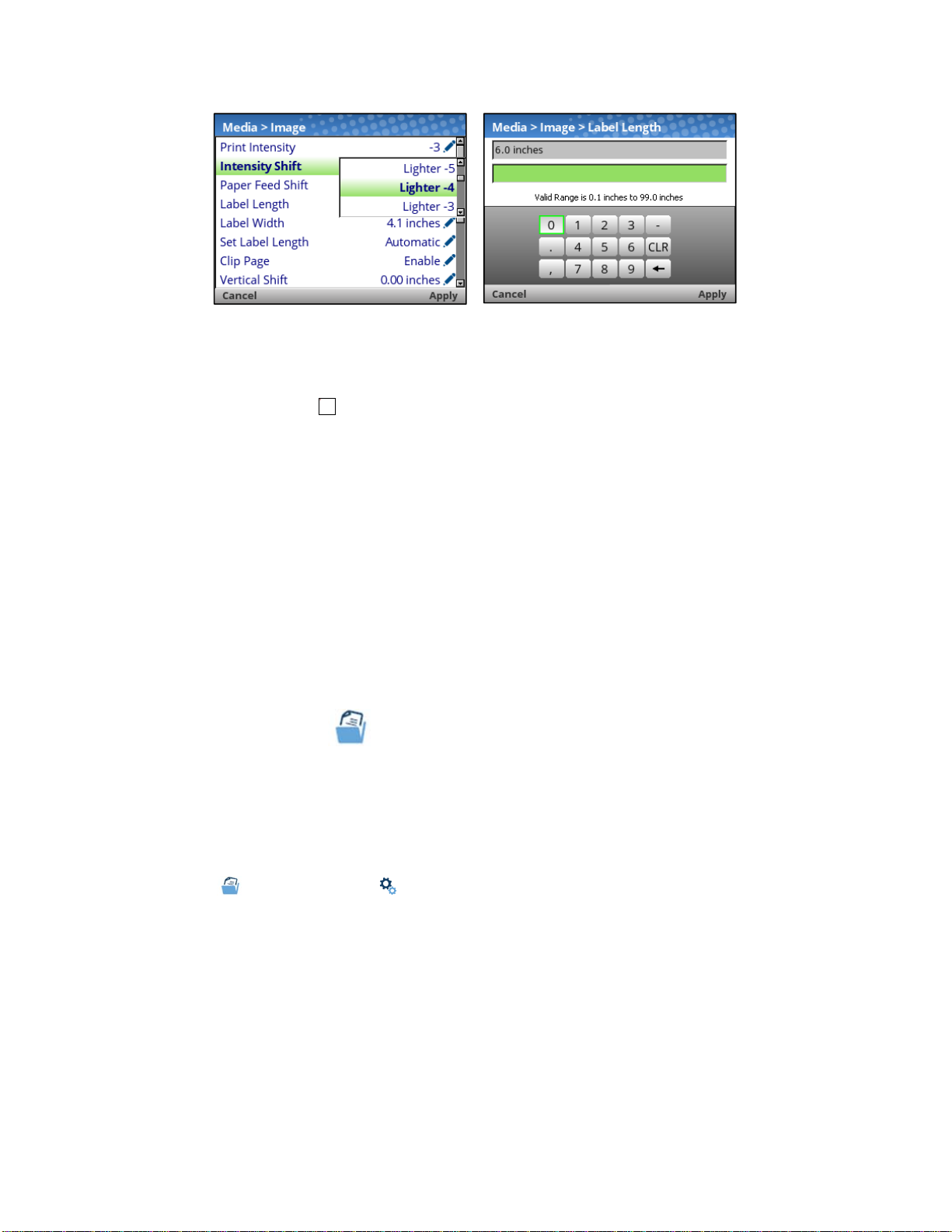
When users are in Edit Mode, they can change to new value by either pressing the
ENTER key, or
using the RIGHT SOFT key to “Apply”. Likewise, the users can exit Edit Mode without any modification to
the menu by using the LEFT SOFT key to “Cancel” the operation.
The linked image cannot be
displayed. The file may have
been moved, renamed, or
deleted. Verify that the link
points to the correct file and
For menus with an action icon , the user can execute the particular action by pressing the
location.
ENTER
key. For menus without any icon, these are read-only menus and cannot be modified.
IMPORTANT Some sensitive menu operations require the user to confirm they want to pro-
ceed. For example menu operations that clear logs, delete configuration, delete
files, etc. In these cases, a message will appear on the screen asking them to
confirm by pressing “OK” with one of the soft keys.
Users can return to the View Level by pressing the left arrow key or go to the Home menu screen by
using the LEFT SOFT key labeled “Home”.
NOTE: Changing menu values as described in this section only changes the Current Co nfiguration.
The Current Configuration is stored in DRAM and is in effect only while the printer is powered
on. To store a configuration permanently into FLASH memory, see Saving a Configuration
page 54 in the next section.
Saving a Configuration
When you make a change to the configuration menus, your changes reside in the Current Configuration
saved in DRAM. The Current Configuration is in effect while the printer is powered on.
If you want to save your configuration permanently into FLASH memory, then you have two options:
Save the configuration by following the instructions within the Auto Save feature when you return to
the ONLINE state.
Select the
Configs icon under Settings and save the configuration with Configs > Control >
Save Config.
Your printer by default has a Factory Configuration. You can save up to eight d i f f e r ent configurations to
meet unique print job requirements. Using the Configs > Control section, you can save, load, print, delete,
and choose which configuration will be active at power-up.
54
Page 55
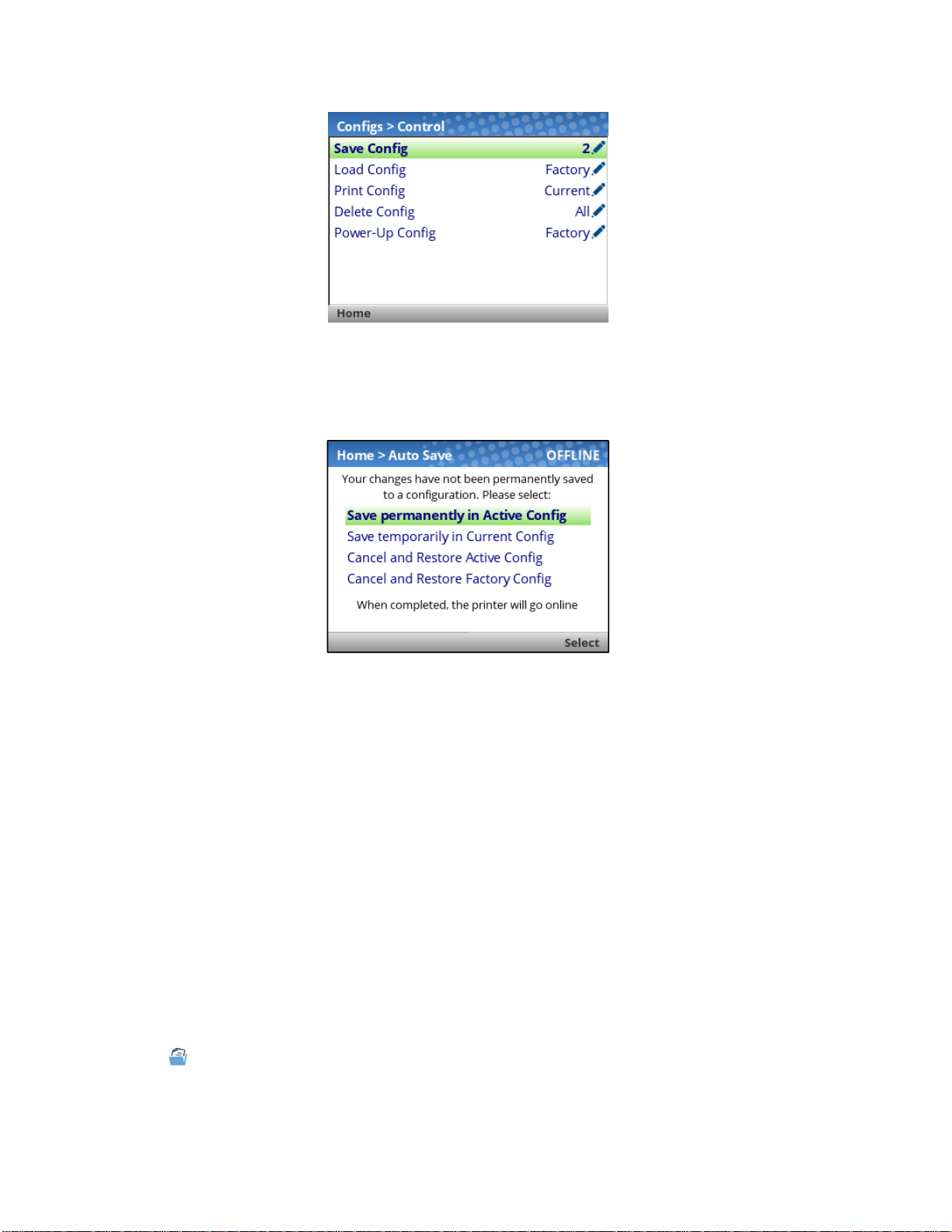
Aut o S av e Configuration
If you make any changes to the current configuration menu items and do not save them manually via the
Configs > Control > Save Config menu, you will be
printer ONLINE with the screen shown below.
prompted to save the changes just before you place the
The Active Configuration is defined as the power-up configuration or last loaded configuration. There
are three possible cases with this choice depending on the state of the printer:
If the Active Configuration is one of the eight user-defined configurations, the Active Configuration will
be saved and made the Power-Up Configuration.
If the Active Configuration is the Factory Configuration, the printer will save the configuration to the
first free (unsaved) configuration and make that open configuration the Power-Up Config.
If the Active Configuration is the Factory Configuration and there are no free (unsaved) configura-
tions, then the user will be informed with a message and asked to save the changes manually. The
printer will return to the Home Screen.
The Current Configuration is the configuration stored in DRAM. If the user selects this option, the
configuration will not be saved into FLASH memory permanently but will continue to be active.
The user also has the option of cancelling their changes by loading either the Active Configuration or the
Factory Configuration.
Once the selection is made, the user will return to the ONLINE state automatically.
Naming Configurations
You may specify a 15-character name which can be used to refer to a configuration in the Configs >
Custom section. The name you enter for a configuration will then be used everywhere within the
Config
section. The names can be cleared by using the Configs > Custom > Reset Cfg N ames menu.
55
Page 56
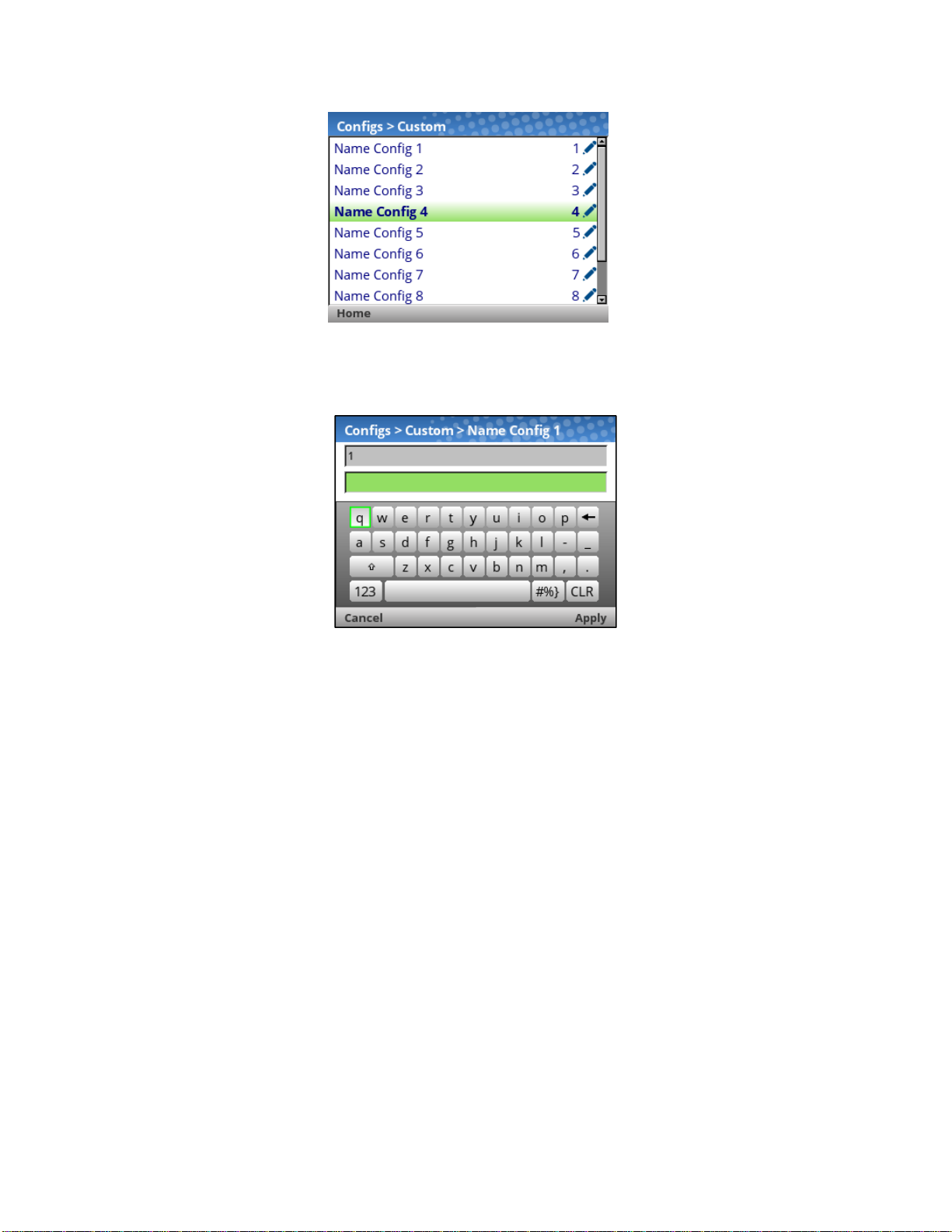
When a configuration to name is selected, a virtual keyboard will be provided for the user to enter the
name desired. The navigation keys can be used to find characters with the ENTER button used to select
them. When the string is complete, the user should use the RIGHT SOFT key labelled “Apply”.
Loading a Configuration
You can specify any one of the nine configurations (1-8 or Factory) to load into DRAM using the Configs >
Control > Load Config menu. If the selected configuration has not been saved, the user will be warned
with a “CONFIG DOES NOT EXIST” message on the pane.
56
Page 57

Specifying a Power-Up Configuration
You can specify any one of the nine configurations (1-8 or Factory) as the power-up configuration using
the Configs > Control > Power-Up Config menu. If the selected configuration has not been saved, the
user will be warned with a “CONFIG DOES NOT EXIST” message on the panel.
Modifying a Saved Configuration
Configurations can be modified and saved (updated) as often as desired. You can load a configuration of
choice with Configs > Control > Load Config, change the menu or configuration parameter of interest and
either use the Auto Save feature or return to the Configs > Control > Save Config menu to save the
changes.
Viewing the Current Configuration
The Current Configuration can be easily viewed on the control panel by selecting the RIGHT SOFT key
labeled “Info” on the Home screen. This will provide the same information in a Configuration Printout
except it is viewable on the control panel.
As can be seen from the picture, the user can scroll through the configuration values and choose to print
the configuration using the RIGHT SOFT key labelled “Print”.
Printing a Configuration
We recommend that you print and store all saved configurations for future reference. The printout
provides a list of the parameters that were set when
printed using the Configs > Control > Print Config menu. That menu has the following options:
Current (the default)
Factory
Power-Up
All
Saved Configurations 1-8
you configured the printer. Configuration can be
57
Page 58

Settings Organization
This section will show how the configuration menus are organized under the icons in the Settings sectio n.
Screen #1
Media
Speed
Image
Handling
Ribbon
Top of Form
Faults
Auto Label Map
Application
Control
PS/PDF Setup
IPDS Setup4
TN 5250 Setup
TN 3270 Setup
PGL … MGL Setup
LP+ Setup
3
5
5
Sensors
Control
Calibrate
Diagnostics
Host I/O
Control
Centronics
IEEE-1284
USB
Serial
6
6
System
Control
Energy Star
Flash File View
Flash File Edit
SD File View
SD File Edit
1
1
Printer Mgmt
3
GPIO
Network
Control
Ethernet
WLAN
WLAN Security
7
7
P-Series … Setup
Fonts
Screen #2
Configs
Control
Custom
Validator8
Control
Grading
Scanner
Diagnostics
Tools
Print Tests
Diagnostics
Statistics
About
Statistics
NOTES:
1
The SD related submenus will only show when the SD card is installed.
2
The GPIO section will be included when the GPIO option is installed.
3
PS/PDF requires the Postscript/PDF firmware and does not include any other emulation.
4
IPDS is an option that can be activated within the standard firmware.
5
TN 5250 and TN 3270 require unique firmware. IPDS and PS/PDF are not available with TN.
6
Parallel is an option and these submenus are included only when Parallel is installed.
7
WLAN is an option and these submenus are included only when WLAN is installed.
8
Validator is only available when ODV option is installed. Refer to t h e Online Data Validator User’s
Manual for information on these menus.
58
Page 59

Media
IMPORTANT All distances under Media can be represented in inches or millimeters based
on the menu System > Control > Media Units.
Intro: Label Length
Understanding your media and application is very important when configuring the parameters in the menu
system. When setting label length, consider the following:
Label Length can be manually entered via the control panel Media > Image > Label Length menu or sent
via the host application (e.g., PGL job) using the appropriate software
command, that is referred to as a Host Form Length or Logical Label Length.
A Host Forms Length (Label Length) value sent from the host compu ter can
Label Length value if the emulation chooses to do so. Often, the emulations will have a menu to configure
that behavior (e.g., Application > PGL Setup > Host Form Length).
Physical Label Length is the actual measurable length of the label. The
types explains how the physical label
lengths are determined:
• Die-cut labels – measurable length of the removable label (leading
does not include the liner material or gap.
• Ta g St ock with notches or holes – measurable length from the trailing
hole to the leading edge of the next notch or
hole.
• Tag Sto ck with black marks on underside – mea surable length from
black mark to the leading edge of the next
black mark.
command. If sent via a software
override Media > Image >
following list of different media
edge to trailing edge). This
edge of one notch or
the leading edge of one
• Continuous media (no label length indicators) – measurable len gth
the Label Length value entered in the Media > Image > Label Length menu or the value sent via
host software command.
Logical Label Length (or Host Forms Length) is the length that a user o r
printable image on. In most cases this length
allows the
holes, or black marks).
When the Logical Label Length is greater than the Physical Label Length
is “Enable”, the printer will
this case, the printable data that was not printed will be lost. There is more on Clip Page menu in the next
section.
entire image to be printed within the boundaries of the label length indicators (gaps, notches,
clip the bottom portion of the image that exceeds the Physical Label length. In
should be slightly less than the Physical Label Length. This
and Media > Image > Clip Page
should be within ± 1-2%
programmer bases his
Intro: Clip Page
The media sensor looks for the gap, notch, hole, or black mark only after the media has advanced the
distance specified by the Media > Image > Label Length menu or by the Host Forms Length coming from
the application. Any gaps, notches, holes, or black marks that exist prior
Host Forms Length value are ignored.
When Media > Image > Clip Page is “Disable”, Mark and Gap media sensing reliability
and the sensor problems described below can be fixed:
The image starts to print at an erroneous distance from the top-of -
a roll where the media is severely
The image is incorrectly positioned as a result of the media sensor
image on the label or multiple gaps
curled or scalloped.
within the label.
to reaching the Label Length or
can be improved
form, especially towards the end of
triggering off of a dark, pre-printed
59
Page 60

The printer starts to print one label and then a nother all on the sam e
end of a roll where the media is
An occasional blank label appears within a print job (in between
When Clip Page is “Disable”, the printer ignores any pre-printed dark
could mistakenly be detected as
Label Length value.
severely curled.
the next top-of-form position based on the specified Media > Image >
physical label, especially at the
printed labels).
marks or multiple gaps on a label that
IMPORTANT When Clip Page is “Disable”, the correct Media > Image >Label Length value
must be
or mark it needs to detect.
When using Gap sensing, the Label
able
label.
When using Mark sensing, the Label Length value is the
one black mark to the
When the Logical Label Length is greater than the Physical Label Length
printer will continue to print the image onto
Media > Image > Label Length value.
When the Logical Label Length is less than the Physical Label Length, the
and leave blank space the remaining
next
label. This is true regardless of the Media > Image > Clip Page setting.
entered. If the value is too long, the printer will ignore the actual gap
Length value is equal to the physical length of a die cut or remov-
physical distance from the leading edge of
leading edge of the next black mark.
and Clip Page is “Disable”, the
the next physical label and ignore the gap or mark b ased on the
printer will print the entire image
length of the physical label as it advances to the Top-of-Form of the
Media > Speed
This option specifies the speed in inches per second (ips) at which the media
passes through the printer while printing.
Minimum 1 ips
Maximum
Factory Default 6 ips
This option sets the speed at which the media moves in reverse direction.
Minimum 1 ips
Maximum 6 ips
Factory Default 2 ips
IM-
PORTANT
Media > Speed > Print Speed
8204: 14 ips, 8304: 12 ips
8206: 12 ips, 8306: 10 ips
8208: 10 ips, 8308: 8 ips
Media > Speed > Reverse Speed
Speeds above 2 ips may cause ribbon smudging
depending on
ribbon and media.
60
Page 61

The speed at which the printer moves media without actually printing on it.
Media > Image
This option specifies the level of thermal energy from the printhead to be
used
heat (thermal energy) to be applied for each dot.
fect on print quality. The print intensity and speed
and ribbon type to obtain the best possible print quality and barcode grades.
Factory Default -3
PORTANT
This menu can be used to shift Print Intensity settings higher or lower. This
allows for higher print intensity settings for certain media while m aintaining
a compatible Print Intensity value set by the host job. It can also be used to
make slight adjustments for compatibility with other emulations.
Factory Default 0
PORTANT
Media > Speed > Slew Speed
Automatic Always the same as the print speed.
Manual
Manual
Factory Automatic
Allows you to set the slew speed. The ra n g e i s co n s i s t e n t
with Print Speed.
Allows you to set the slew speed. The maximum follows the Print Speed maximum.
Media > Image > Print Intensity
for the type of media and ribbon installed. Large numbers imply more
This has a significant ef-
must match the media
Minimum -15
Maximum +15
The actual print intensity is the sum of both the
Print Intensity menu and the Intensity Shift menu.
IM-
For example, if Print Intensity = 5 and Intensity
Shift = -3, then the actual print intensity used is 2.
However, the actual intensity is bounded with a
minimum of -15 and maximum of 20.
Media > Image > Intensity Shift
Minimum -10
Maximum +10
IM-
While the shift can swing -10 to +10, the actual
print intensity value is bounded with a minimum
of -15 and maximum of 20.
61
Page 62

Media > Image > Paper Feed Shift
This option represents the distance to advance (+ shift) or pull back (– shift)
the stop position of a label when Tear-Off Strip, Tear-Off, Peel-Off, or Cut
Media Handling option is enabled. Allows .01 inch increments.
Minimum -1.00 inches
Maximum Current Label Length (or 12.80 inches maximum)
Factory Default 0.00 inches
Media > Image > Label Length
This option specifies the user-selected Label Length. In most applications,
the user-selected Label Length will match the physical
cal label length is the actual label length of the media
Die-cut Labels: Measurable length of the removable label (leading edge to
trailing edge). This does not include the liner material o r gap.
Ta g St ock with notche s or holes: Measurable length from the trailing
one notch or hole to the leading edge of the next notch or
Ta g Stock with black marks on underside: Measurable length from
ing edge of one black mark to the leading edge of the next
Continuous media (no label length indicators): Measurable length should be
within ± 1-2% the Label Length value here or the value sent via host software command.
label length. Physi-
installed:
hole.
the lead-
black mark.
edge of
Minimum 0.1 inches
Maximum 99.0 inches
T8x04: 6.0 inches
Factory Default
IM-
PORTANT
T8x06: 4.0 inches
T8x08: 6.0 inches
This menu can be overridden by the host job
(Host Form Length) and set to values that do not
match the physical length. For a full description of
how Label Length behaves, see the section Intro:
Label Length.
62
Page 63

Media > Image > Label Width
This option specifies the physical width of the image to be printed.
Minimum 0.1 inches
Maximum Maximum based on printer model/printhead.
T8x04: 4.1 inches
Factory Default
T8x06: 6.6 inches
T8x08: 8.5 inches
Media > Image > Set Label Length
This feature selects whether the Sensed Distance value derived from an
Auto or Manual Calibrate will be used to set the Label Length menu. If no
calibration is performed, this menu has no effect.
Manual
Automatic
Factory Default Automatic
IM-
PORTANT
The Sensed Distance will not override or change the
Label Length value.
The Sensed Distance value will override and change
the Label Length value. If Sensors Control >
Gap/Mark Sensor = Gap, Advanced Gap, or Advanced Notch, the printer will subtract the Sensors >
Calibrate > Gap Length value.
For Automatic setting, the Sensors > Calibrate >
Use Label Length is ignored (treated as disabled).
63
Page 64

Media > Image > Clip Page
This option determines how the printer handles images that are too large for
one physical page length when using gap or black mark media.
When the user-selected page length (logical length) is
greater than the physical page length dictated by the
Disable
Enable
Factory Default Enable
gap, notch, hole, or black mark on media, the printer
continues to print the remaining excess data onto the
next physical page.
The printer clips any excess data to fit the physical
page. The excess data is lost. The media sensor constantly looks for the gap, notch, hole, or black mark
and when detected, uses it as the TOF position for
the next label and clips any remaining data.
IM-
PORTANT
This option specifies the amount to shift an image vertically up (-) or down
(+) for precise positioning on the label. The actual height of the image is not
affected by this parameter. The adjustment is made in .01 inch increments.
Minimum -1.00 inches
Maximum Label Length (max 12.80 inches)
Factory Default 0.00 inches
This option specifies the amount to shift an image horizontally left (-) or right
(+) for precise positioning on the label. The actual width of the image is not
affected by this parameter. The adjustment is made in .01 inch increments.
Minimum -1.00 inches
Maximum +1.00 inches
See Intro: Clip Page 59 for more explanation when
this menu option is disabled.
Media > Image > Vertical Shift
Media > Image > Horizontal Shift
64
Factory Default 0.00 inches
Page 65

Media > Image > Orientation
This menu item selects the image orientation to be used when printing the
label. Se e p i c tu r e b el o w fo r a n i l l us t r at i o n .
Portrait
Landscape
Inv. Portrait
Inv. Landscape
Factory Default Portrait
IM-
PORTANT
Portrait refers to vertical page orientation, where the
top of the page is at the leading edge.
Landscape is a rotation of the logical page at 90 degrees clockwise from Portrait.
Inverse Portrait is a rotation of the logical page at 180
degrees from Portrait.
Inverse Landscape is a rotation of the logical page at
270 degrees clockwise from Portrait.
The orientations shown here are with Print Direction set to Head First. Some IGP Emulations such
as ZGL use Foot First. In that case, the orientations would be 180 degrees different for all selections shown here.
65
Page 66
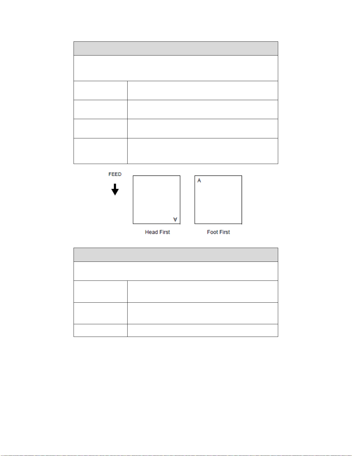
Media > Image > Print Direction
This option is the compass for print orientation. Not all IGP Emulat ion languages have the same definition of Portrait, Landscape, etc. The illustration below
shows how Portrait is defined for both Head First and Foot First.
Head First
Foot First
Factory Default
IM-
PORTANT
With Orientation set to Portrait, the top of the label will
come out of the printer first.
With Orient a t i on s et t o Portrait, the bottom of the label
will come out of the printer first.
Head First for PGL, but Foot First for ZGL. It will automatically be set for plug’n play compatibility.
Print Direction will not change the orientation of
any print test patterns in the Tools > Print Tests
menu.
Adjusts the vertical print resolution. This can be used to compress or expand all printed forms by small amounts.
Minimum
Maximum
Factory Default Match Head DPI
Media > Image > Vertical DPI Adj
195 (203 DPI)
290 (300 DPI)
210 (203 DPI)
310 (300 DPI)
66
Page 67
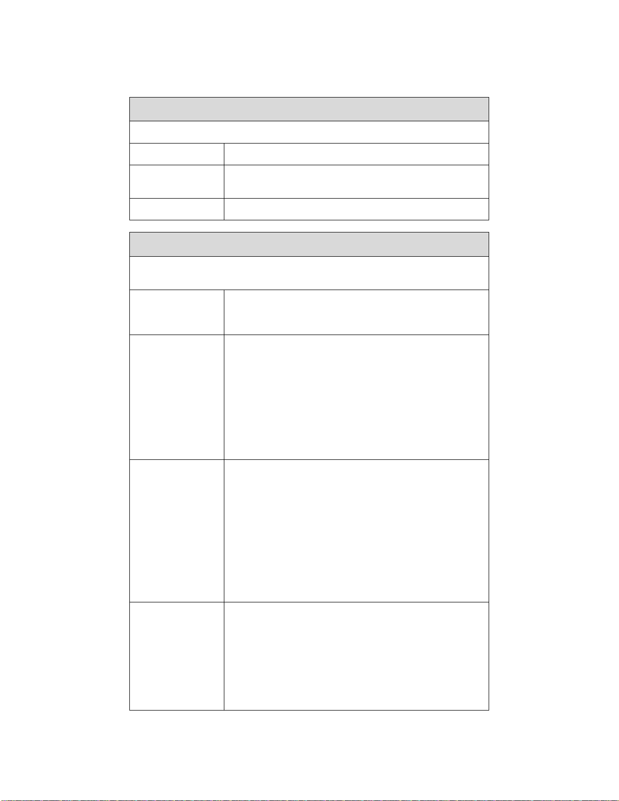
Media > Handling
This option specifies the type of printing to be done.
Transfer Indicates Thermal Transfer printing (ribbon installed).
Media > Handling > Print Mode
Direct
Factory Default Transfer
Indicates Direct Thermal printing (no ribbon) and requires special heat sensitive media.
Media > Handling > Media Handling
This option specifies how the printer will handle the media (labels or tag
stock).
Printer prints on the media and sends it out the front
Tear-Off Strip
Tear-Off
until the print buffer is empty, then positions the last
label over the tear bar for removal.
After each label is printed, the printer positions the label over the tear bar and waits for you to tear off the
label before printing the next one (on-demand printing). A “Remove Label” message will display to remind you to remove the label before the next one can
be printed.
Not allowed if the cutter is installed. The error message “INCOMPATIBLE WITH CUTTER” displays.
Prints and peels die-cut labels from the liner without
assistance. The printer waits for you to take away the
label before printing the next one (on-demand printing). When the optional internal rewinder is installed
with liner attached, a “Remove Label” message will
Peel-Off
Cut
display to remind you to remove the label before the
next one can be printed. See Label Peel-Off page 29
and Media > Handling > Peel Present table page 69
for more information.
Not allowed if the cutter is
sage “INCOMPATIBLE WITH CUTTER”
When the optional media cutter is installed, it automatically cuts media after each label is printed or after
a specified number of labels have been printed when
a cut command from the host has been issued. It cuts
continuous roll paper, labels, or tag stock.
Only allowed when the cutter is installed. The error
message “OPTION NOT INSTALLED” displays otherwise.
installed. The error mes-
displays.
67
Page 68
Media > Handling > Media Handling
Printer prints on the media and sends it out the front.
Continuous
Factory Default Tear-Off Strip
See Media > Handling > Continuous Mode table page
68 for more information.
Media > Handling > Continuous Mode
Allows selection of special media modes when Continuous Media Handling
mode (see Continuous media page 62) is selected.
Labels are printed and sent out the front. The cross
perforation following the last printed label is not
aligned at the tear bar. No auto feeding of a blank la-
Standard
bel should exist between print jobs, but you may need
to press the FEED key to move approximately .80
inches of the last printed label from under the printhead. If performed, this feed causes a blank label at
the beginning of the next print job.
Tear-Off
Tear Strip Full
Cut Strip
Same as Standard, but the cross perforation following
the last printed label is aligned at the tear bar. No
blank label is needed to remove the last printed label.
No blank label should exist between print jobs. A no
print zone, .80 inches long, exists from the leading
edge of each printed label. This option supports label
lengths 2.50 inches or longer.
Same as Standard, but the cross perforation following
the last printed label is automatically aligned at the
tear bar once the print buffer is empty for a period of
Tear-Strip Time. (Media does not get aligned at tear
bar until Tear-Strip Time expires.) When printable
data is again detected, a blank label is automatically
fed, resulting in one blank label between each print
job. This option supports label lengths 2.50 inches or
longer. Shorter label lengths cause two or more blank
labels to be automatically fed at the beginning of each
print job.
When Media Handling is set to Continuous and a cutter is installed, Cut Strip will use the respective host
interface Timeout menu setting to determine the End
Of Job (EOJ) and cycle the cutter. That is, the cutter
will be cycled when there is no more data being received from the host. The cut will not be done for
printing that is not initiated by the host such as form
feeds and test printing or if the host interface is not
set to Auto Switching.
68
Factory Default Standard
Page 69

Media > Handling > Peel Present
This feature allows you to select which part of a label gets presented to the
peel bar.
Media is moved to next TOF after image printing before presenting media to the peel-off position. This op-
Next TOF
End of Form
End of Image
tion is for standard labels where the gap/mark length
is less than the printhead to peel bar distance (about
1/2 inch).
Media is moved to the end of form after image printing
before presenting media to the peel-off position. This
option is for labels that have wide gaps that result in
labels falling off the peel bar. This setting works with
non-mark media where the end of form is not the
same as the next TOF. This setting is useful for die
cut labels where the physical bottom of the label can
be detected by the media sensor.
Image prints and media moves to peel-off position.
This option is for labels that have wide gap/marks that
result in labels falling off the peel bar. This selection is
intended for cases where presenting the next TOF or
end of form still results in labels falling off the peel
bar. This menu selection works best if the length of
the image printed matches the physical length of the
label.
Factory Default Next TOF
IMPORTANT
End of Image selection is affected by the Media >
Image > Clip Page option.
Media > Handling > Peel-Off Mode
When Peel-Off Media Handling mode is enabled, this feature allows selection of two different media motions for automatic label peel-off.
Reverse and forward media motion distance in Peel-
Fast
Standard
Factory Default Fast
Off mode is reduced, providing faster throughput. Primarily used for label lengths less than 2 inches long.
Provides standard reverse and forward media motion
distance in Peel-Off mode to ensure sufficient rewinder tension.
69
Page 70
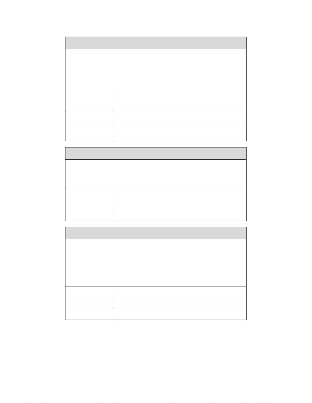
Media > Handling > Pre-Peel Mode
Pre-Peel Mode adds a forward and reverse motion to each label prior to
printing. The added forward pre-peel motion temporarily breaks the die cut
label from the liner, and the reverse motion places the label back on the
liner prior to printing, peeling, or dispensing the label. Pre- Peel Mode is
usually enabled only when using die cut labels with an aggressive adhesive
that makes automatic label removal from the liner difficult.
Disable No motion.
Enable Enables the forward and reverse motion prior to print.
Factory Default Disable
IM-
PORTANT
Only applies when Media Handling is set to PeelOff and Peel-Off Mode is set to Standard.
Media > Handling > Pre-Peel Adjust
When Pre-Peel Mode is set to Enable, Pre-Peel Adjust represents the selectable distance that the label advances during Pre-Peel Mode. The PrePeel Adjust distance selected is automatically used when Pre-Peel Mode is
enabled. Increments in 0.01 inches.
Minimum 0.00 inches
Maximum 2.00 inches
Factory Default 1.00 inches
MEDIA > Handling > Label Wait Time
Media Handling is set to Tear-Off Strip or Continuous (Tear Strip Full):
Label Wait Time specifies the number of seconds after printing stops that
the printer will wait before it advances media to the tear bar position.
Media Handling is set to Peel-Off, Tear-Off:
Label Wait Time
label is removed
specifies the number of seconds the printer will wait after a
from the peel/tear bar before starting to print the next label.
Minimum 0.1 seconds
Maximum 60.0 seconds
Factory Default 0.1 seconds
70
Page 71
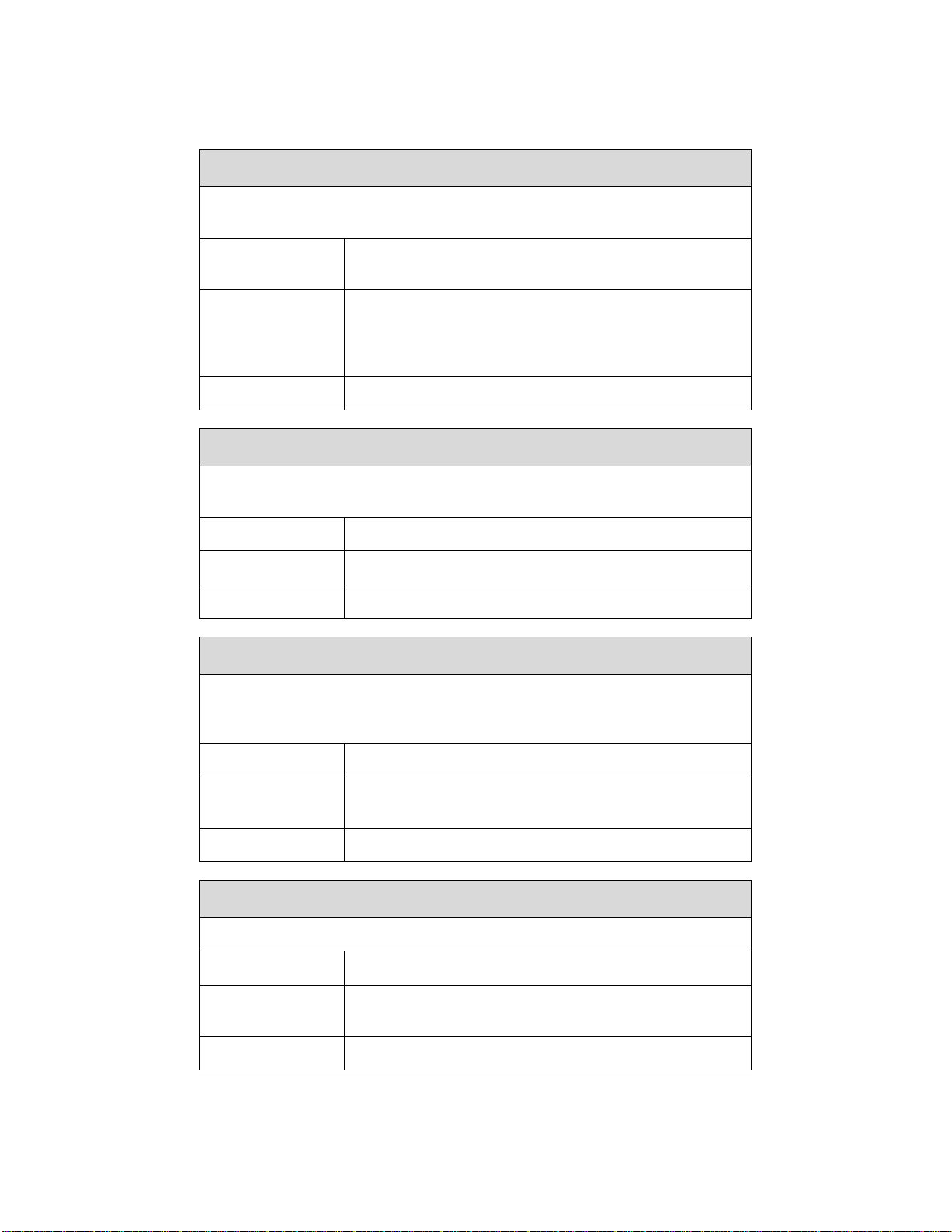
Media > Ribbon
Sets the ribbon operating parameters automatically based on the label settings or manually if the media width is less than the ribbon width.
Media > Ribbon > Ribbon Width
Same as Paper
Set in Menu
Factory Default Same as Paper
The printer automatically adjusts the ribbon operating
parameters to match the installed media width.
In those cases where the media width is less than the
installed ribbon width, this option should be selected.
After selection, the menu “Ribbon Width Adj” is unhidden and is used to determine the ribbon width.
Media > Ribbon > Ribbon Width Adj
When the menu Ribbon Width is set to “Set in Menu”, this menu is unhidden
and can be used to set the proper Ribbon Width value.
Minimum 0.1 inches
Maximum Maximum based on printer model/printhead.
Factory Default 0.1 inches
Media > Ribbon > Ribbon Low
When enabled and the amount of ribbon remaining on the supply spindle is
approximately 75 to 50 meters or less, a “Ribbon Low” warning will pop up
on the ONLINE screen.
Disable No Ribbon Low warning will appear.
Enable
Factory Default Disable
The Ribbon Low warning will appear when the ribbon
on the supply spindle is 75 meters or less.
Media > Ribbon > Takeup Full
This controls a fault message for a Ribbon Takeup Full condition.
Disable No fault message.
Enable
Factory Default Enable
A fault message will occur for a Ribbon Takeup Full
condition.
71
Page 72
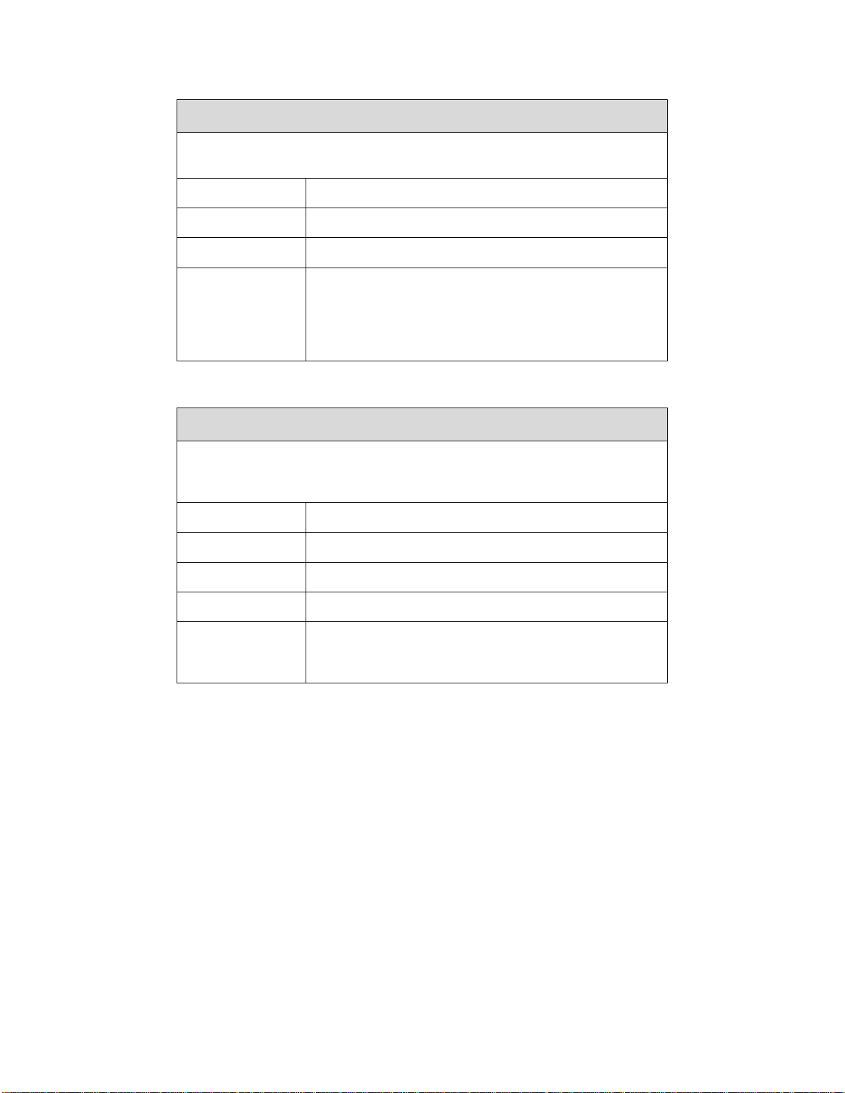
Determines the amount of ribbon remaining by performing a forward or reverse move.
Standard Normal forward and reverse ribbo n calibration.
Forward Only Forward only ribbon calibration.
Factory Default Standard
IM-
PORTANT
Media > Top of Form
Allows selection of three different TOF (Top-of-Form) detection faults. The
printer displays a Gap Not Detected fault and stops printing when media has advanced a distance equal to X or more times Media > Image > Label Length.
Media > Ribbon > Ribbon Calibrate
When GPIO Print & Apply is set to Enable, Ribbon
Calibrate is set to Forward Only. This automatic
setting of the Ribbon Calibrate menu occurs only
once per power cycle and only if the menu is
changed with the control panel.
Media > Top of Form > TOF Detect Fault
1 Label The Gap Not Detected fault is declared after 1 label.
3 Labels The Gap Not Detected fault is declared after 3 labels.
9 Labels The Gap Not Detected fault is declared after 9 labels.
Factory Default 3 Labels
IM-
PORTANT
The correct Label Length value, equal to the physical length of the installed label, must be entered
in Media > Image > Label Length.
72
Page 73

Media > Top of Form > Ticket Save Mode
This option determines the action of the media for Continuous (Standard),
Tear-Off, Tear-Off Strip and Cut Media Handling Modes after the printer is
first powered up or after the printhead has been opened and then closed.
When enabled, this option eliminates wasting label(s) or ticket stock when
the printer advances media to search for the next TOF position.
Option applies only to 0.5 inch or longer label lengths.
The printer assumes that the media is not at the correct
TOF position after cycling power or after the printhead is
opened and then closed. Printing will begin only after the
Disable
Enable
next TOF is detected.
When disabling, Sensors > Calibrate > Online Action
and Sensors > Calibrate > HeadClose Action will not
be adjusted.
The printer will assume that media is at the TOF position after cycling power or after the printhead is opened and then
closed. Printing will begin without advancing media to
search for the next TOF position.
When enabled, Sensors > Calibrate > Online Action
and Sensors > Calibrate > HeadClose Action will automatically be set to Disable.
The printer will assume that media is not at the TOF position
after cycling power but is at the TOF position after the printhead is opened and then closed. After powering up, printing
will begin only after the next TOF is detected. After open-
No Seek
Factory Default Disable
IM-
PORTANT
ing the head, printing will begin without advancing media to
search for the next TOF position.
When enabled, Sensors > Calibrate > Online Action
and Sensors > Calibrate > HeadClose Action will automatically be set to Disable.
The user must ensure that media is at the correct
TOF position (cross perforation, liner gap, notch
or mark at the tear bar edge) before cycling power
or before closing and locking the pivoting deck. In
addition, media must be calibrated and the correct
Media Handling Mode, Label Length and Gap/Mark
Sensor selected and saved as the Power-Up Config.
73
Page 74

Media > Top of Form > Adjust Mode
This option enables use of the Media > Top of Form > TOF Adjust distance.
Disable The TOF Adjust menu value will not be used.
Enable Th e T O F A d j u s t m e n u v a l u e w i l l b e u s e d .
Factory Default Disable
Media > Top of Form > TOF Adjust
This option sets the distance from the Top Of Form (TOF) that is left blank
(unprinted) after a label has been removed in Tear-Off strip or Tear-Off
mode. When this mode is enabled the start position for printing can be adjusted in increments of 0.01 inch.
This adjustment can be helpful if a die cut label sticks to the platen by
means of jagged edges created during a poor die cut label removal using
the tear bar. By controlling how much blank space there is from TOF, you
can control how much the media is called back after it is torn off.
Minimum 0.00 inches
Maximum 0.40 inches
Factory Default Match Head DPI
IM-
PORTANT
Media > Faults
Tear-Off strip or Tear-Off mode only
74
Page 75
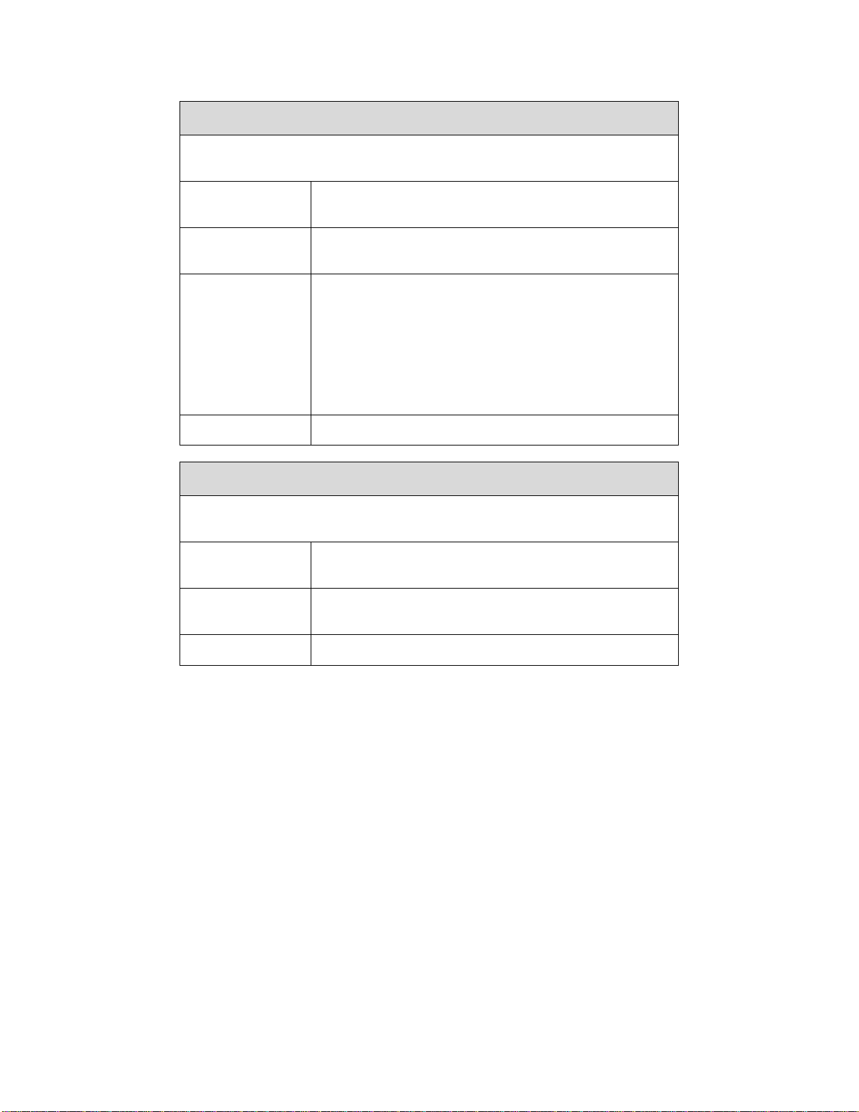
Media > Faults > Label Missing
Allows the Label Taken Sensor to first detect the presence of a label at the
tear bar.
Disable
Full Label
Early Detect
Factory Default Full Label
The printer does not generate a fault condition if a
missing label is encountered.
Peel-Off and Tear-Off Handling: The printer generates
a fault condition if a missing label is encountered.
Tear-Off, Tear-Off Strip, and Continuous Handling: If
no label is detected by the label taken sensor after the
first 1.35 inches of motion, then a LABEL WRAP fault
is declared early.
Cut handling: Ignored.
Peel-Off handling: The settings behave the same as
Full Label.
Media > Faults > Error Recover
This option determines how the printer handles data that was printing when
an error occurred.
Disable
The printer will not reprint the label that was printing
when the error condition occurred.
Enable
Factory Default Disable
Media > Auto Label Map
The printer reprints the label that was printing when
the error condition occurred.
75
Page 76

Media > Auto Label Map > Select
This option specifies the maximum print width to be used by the application.
The IGP/Auto Label Mapping® feature allows backward compatibility of programs written for Printronix line-matrix printers. It allows the printer to print
two-up (or other multi-up) labels. Instead of printing multiple labels across
the printer, it prints the leftmost label and the rightmost label, so the printout
will be twice as long but half as wide.
Excess data in any program sent to the printer with
Disable
Enable
Factory Default Disable
horizontally adjacent labels that exceed the physical
page width of the printer will be clipped or wrapped
depending upon how the emulation is designed.
The printer will automatically reposition the horizontally adjacent labels to a vertically adjacent position,
or a combination of horizontal and vertical positions
based on the values selected under the Auto Label
Width and Num Auto Labels menu items.
Media > Auto Label Map > Auto Label Width
The width of a single label to be printed or the maximum width of the media
that will be used for the print file. The value is selectable from 00.1 inch
through the maximum print width of the printer.
Minimum 0.1 inch
Maximum Media > Image > Label Width value.
Factory Default Depends on the model width.
76
Page 77

Media > Auto Label Map > Num Auto Labels
The desired number of labels to be printed vertically adjacent on the form.
Minimum 2
T8x04: 40
Maximum
Factory Default 2
T8x06: 21
T8x08: 17
Auto Label Map Examples
All of the examples be low assume tha t the logical f orm length is set to the label length.
Example 1: Simple Case
Problem: A file has been constructed with two horizontally adjacent 4.0” label s for a printer with a
physical width of 8.0”. The user now wants to use this file
Solution with Menu Settings:
with a printer that has a 4.0” physical width.
• Set Media > Auto Label Map > Auto Label Width to “4.0” (the width of the label)
• Set Media > Auto Label Map > Num Auto Labels to “2”
• Set Media > Auto Label Map > Select to “Enable”.
Printer Operation: The printer will print the first (leftmost) 4.0” label first on the first thermal label, followed
by the second 4.0” label. These labels will be stacked vertically as shown in the diagram.
Example 2: Uneven Number Case
Problem: A file has been constructed wi th three horizontally adjacent 2.0” labels. The user now desires to
use this file with a printer that has a 4.0” physical widt h.
77
Page 78

Solution #1 with Menu Settings:
• Set Media > Auto Label Map > Auto Label Width to “2.0” (the width of two labels)
• Set Media > Auto Label Map > Num Auto Labels to “2”
• Set Media > Auto Label Map > Select to “Enable”.
Printer Operation for Solution #1: The printer will print the first two labels at
two labels will be horizontally adjacent. Once these
remaining 2.0” labels along
with a blank 2.0” label. See figure below.
labels have been completed, the printer will print the
the same time. These first
Solution #2 with Menu Settings:
• Set Media > Auto Label Map > Auto Label Width to “2.0” (the width of two labels)
• Set Media > Auto Label Map > Num Auto Labels to “3”
• Set Media > Auto Label Map > Select to “Enable”.
Printer Operation for Solution #2: The printer will print the first 2.0” label by
by itself, and finally, the last 2.0” label by itself. See figure below.
itself, the second 2.0” label
78
Page 79

Example 3: Past Maximum File Width
Problem: A file has been constructed wi th three horizontally adjacent 4.0” labels. The user now desires to
use this file with a printer that has an 8.0”
one of the
Auto Label Width of “12.0” and a Me d i a > A ut o L a be l M ap > Num Auto Labels of “3”.
Printer Operation: The maximum Num Auto Labels = (20”/12”) = 1.67 rounded up
automatically reduce the Me d i a > A u t o L a be l M a p > Nu m Auto Labels to “2”.
solutions in the examples above, but the user erroneously enters an Media > Auto Label Map >
physical width. The user should have used a solution similar to
to 2. The printer will
Example 4: Blank Label Case
Problem: A file exists with two horizontally adjacent 4.0” labels. The user now wants to use this file with a
printer that has a 4.0” physical width. The user
“3” and the Media > Auto Label Map > Label Width to “4.0” despite the fact
optimum.
Printer Operation: The maximum Num Auto Labels = (20”/4”) = 5. The
the file is sent, the printer will begin by
print the
a blank 4.0” label.
second 4.0” width label. Finally, once both of those labels have been printed, the printer will print
printing the first 4.0” width label. Once that label is complet e, it will
decides to set the Me d i a > A u t o L a b e l M a p > Num Labels to
that these values are not
selected value of 3 is legal. After
79
Page 80
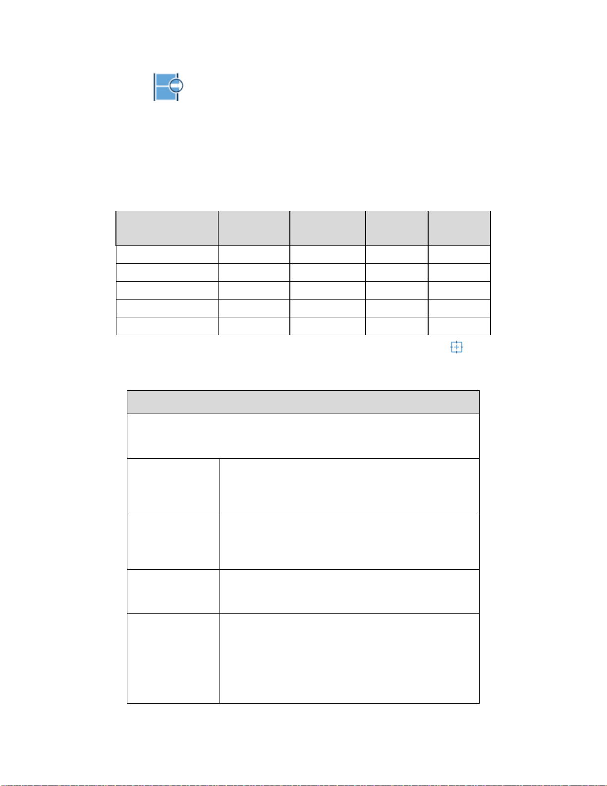
Sensors
Intro: Sensor Types
When making changes in this section, there are certain implications that need to be understood because
some menus are intimately related. For example, when the menu Sensors > Control > Gap/Mark Sensor
is changed, this has an effect on other menu defaults as shown in Table 2.
Table 2. Gap/Mark Sensor Effects on other Menu Defaults
Gap/Mark Sensor
Disable Reflective 48 75 150
Mark Reflective 48 75 150
Gap Reflective 48 75 150
Advanced Gap Transmissive 80 140 190
Advanced Notch Transmissive 80 140 190
Paper Out
Sensor
Min Calib
Delta
Gap/Mark
Thresh
Gap/Mark
Thresh
IMPORTANT When sensors settings are changed, the user must calibrate .
Sensors > Control
Sensors > Control > Gap/Mark Sensor
The available options specify the sensor type needed for detecting the Topof- Form position on media with label length indicators (gaps, notches,
holes, or black marks).
Select when using media with no label length indica-
Disable
tors (no gaps, notches, holes, or black marks), or
when you want the printer to ignore all existing label
length indicators on the installed media.
80
Mark
Gap
Advanced Gap
Select when using media that has horizontal black
marks located on the underside of the label liner or
tag stock. The Top-of-Form position is the leading
edge of the black mark.
An alternative to Advanced Gap. The Top-of-Form position is the leading edge of the die cut label (trailing
edge of the gap, notch, or hole).
Select when using media with a liner space between
die-cut labels or when using tag stock with notches or
holes as label length indicators on white background
media or when using media that has liner gaps between die cut labels with black background. The Topof-Form position is the leading edge of the die cut label (trailing edge of the gap, notch, or hole).
Page 81

Sensors > Control > Gap/Mark Sensor
Select when using media with notches or holes that
Advanced
Notch
Factory Default Advanced Gap
IM-
PORTANT
interrupt a black vertical line on the underside of the
media. The Top-of- Form position is the leading edge
of the die cut label (trailing edge of the gap, notch, or
hole).
When you select Disable, the length of each label
is based on the Media > Image > Label Length
menu or the value sent within the application format.
Sensors > Control > Auto Calibrate
This executable menu is used to improve the sensitivity and reliability of the
Media Sensors in detecting gaps, notches, holes, or black marks on the installed media, as well as a paper out condition. The operation is successful
when the Sensed Distance
media.
For Gap: The Sensed Distance should match the length from the trailing
edge
of one gap to the trailing edge of the next gap (one label + one gap).
For Ma rk : T he Sensed Distance should match the length from the
edge of one black mark to the leading edge of the next black mark.
displayed correctly matches that of the installed
leading
Prior to running Auto Calibrate you must enter the
length of the installed media via the Media > Im-
age > Label Length menus. Selecting the correct
Label Length forces Auto Calibrate to increase
IM-
PORTANT
media advancement for long labels (to detect actual gaps, notches, or marks) and decrease advancement for short labels.
Auto Calibrate supports label lengths up to 35
inches.
81
Page 82

Sensors > Control > Sensed Distance
This value represents the distance that was sensed between the TOF of
one label to the TOF of the next label upon successful calibration. It is a
read-only value.
Gapped media: the distance equals the physical label length plus one gap,
notch, or hole (trailing edge of one gap, notch, or hole to the trailing edge of
the next gap, notch, or hole).
Black mark media: the distance equals the leading edge of one black mark
to the leading edge of the next.
Setting Automatically calculated upon calibration.
Factory 0.0 inches
Sensors > Control > Gap/Mark Thresh
This menu item sets a value that, when exceeded by the output of the media sensor, is recognized by the printer as a gap (or black mark). Upon calibration, the value displayed is equal to the gap/mark threshold value set by
the procedure. If running the procedure does not provide a reliable Top-OfForm detection (e.g., when using unusual media), the Gap/Mark Thresh
value can be manually set to the desired value.
Minimum 0
Maximum 1023
Factory See Table 2
Sensors > Control > Paper Out Thresh
This menu item selects a value that, when exceeded by the output of the
media sensor, is recognized by the printer as a paper out condition. Upon
calibration, the value displayed is equal to the paper out threshold value set
by this procedure. If running the procedure does not provide a reliable paper
out detection, e.g., when using non-standard media, the Paper Out Thresh
value can be manually set to the desired value.
Minimum 0
Maximum 1023
Factory See Table 2
82
Page 83
Sensors > Control > Paper Out Sensor
Selects which type of media sensing, Transmissive or Reflective, will be
used to detect a paper out condition. The printer automatically selects the
type of sensing based on the Gap/Mark sensing selected as shown in Table
2.
Reflective Use reflective sensor for paper out sensing
Transmissive Use transmissive sensor for paper out sensing
Factory Transmissive
Whenever you select Transmissive, you must po-
IM-
PORTANT
sition the upper media sensor directly over the
lower media sensor (see Positioning the Media
Sensors page 34).
Sensors > Calibrate
You can run Auto Calibration from the Home screen, this section, or the Tools > Print Tests > Run Test
menu. Upon execution, the printer advances media the distance needed to accurately detect the label
length indicators, then stops at the Top-of-Form position, and momentarily displays the Sensed Distance
if successful. This process takes a few seconds to complete and results in changes to the values the
printer uses in the Sensors > Control subsection for Gap/Mark Threshold, Paper Out Threshold, and
Sensed Distance. These value changes take effect immediately within the current configuration menu.
Sensors > Calibrate > Auto Calibrate
See Sensors > Diagnostics > Media Profile
Sensors > Calibrate > Power-Up Action
Calibration activities when the printer is powered up.
Disable No activities at power up.
Auto Calibrate is performed at power-up. Once the
Auto-Cal
Seek TOF
Factory Auto-Cal
IM-
PORTANT
Auto Calibrate is complete, the printer will momentarily display the Sensed Distance determined by the
Auto Calibrate.
Assumes user has already calibrated media and used
gap/mark sensor. This moves the media to Top-ofForm at power up if Sensors > Control > Gap/Mark
Sensor is not set to Disable.
If Media > Top of Form >Ticket Save Mode is set,
Auto-Cal and Seek TOF will not be performed.
83
Page 84
SENSORS > Calibrate > HeadClose Action
Selects whether the printer performs a selected action after a print head
open fault condition is cleared.
Disable
Auto-Cal
Seek TOF
Factory Disable
No media motion after a print head open fault condition is cleared.
Performs Auto Calibration every time the print head
open fault condition is cleared.
Moves the media to TOF (Top Of Form) when the
printhead is closed unless Sensors > Control >
Gap/Mark Sensor is set to Disable.. The media should
already be calibrated using Gap/Mark sensor.
If Media > Top of Form >Ticket Save Mode is set,
Auto-Cal and Seek TOF will not be performed.
IM-
PORTANT
If there is data pending (data in buffer) when the
head open fault is cleared, Auto-Cal and Seek TOF
are ignored.
Sensors > Calibrate > Online Action
Whenever the printer is brought ONLINE, it automatically performs an Auto
Calibrate if enabled. This option should only be set before any data is sent
to the printer.
Disable
Enable
Factory Disable
IM-
PORTANT
No Auto Calibration is performed when going
ONLINE.
Once the Auto Calibrate is complete, the printer momentarily displays the Sensed Distance and then resumes printing any pending jobs.
If Ticket Save mode is enabled, you will not be
able to enable this menu. A warning message will
be displayed instead.
84
Page 85

Sensors > Calibrate > Cal in Peel Mode
This option allows you to perform a calibration in Peel-Off Media Handling
mode. Calibration in Peel-Off mode does not stop and wait for you to remove peeled labels. Therefore, be prepared to remove the labels as they
are automatically peeled.
Disable
Enable
Factory Disable
IM-
PORTANT
Calibration from the panel when in peel mode is not
permitted and a warning message will display.
Auto Calibrate can be performed from the front panel
in peel mode.
If this menu is set to Disable, then Power-Up Action = “Auto-Cal” is ignored.
Sensors > Calibrate > Gap Windowing
This feature compensates for any early falling edges or spurious peaks and
troughs that may appear within the gap length in media. These edges or
peaks and troughs can cause unreliable detection of the leading edge of the
next label (top-of-form). Use Gap Windowing to resolve the following problems:
Loss of one or more complete (serialized) labels.
Start of an image printed in the middle of a gap, especially with fanfold,
forated media.
Top part of an image lost when printing in head-first orientation.
per-
When the leading edge of a gap is detected, the
printer continuously looks for the leading edge of the
Disable
Enable
Factory Disable
next label and uses it as the TOF position. Perforations or unusual media discrepancies within the gap
can cause inaccurate TOF detection.
When the leading edge of a gap is detected, the
printer ignores the first 90% of the gap length value
specified in the Gap Length menu option. The result is
that cross perforations or unusual media discrepancies within the gap are filtered out, allowing the printer
to reliably detect the actual leading edge of the next
label and use it as the TOF position.
85
Page 86
Sensors > Calibrate > Gap Length
Gap Length is the actual length (height) of a label gap measured in .01 inch
increments.
Minimum 0.05 inches
Maximum 1.00 inches
Factory 0.12 inches
You must enter the correct Gap Length. If the Gap
WARNING
Length is too long, the image will shift down from
the leading edge (TOF) of the label.
Sensors > Calibrate > Minimum Delta
This menu changes the minimum threshold value the sensor(s) require to
detect the difference between the label and a gap, notch, hole or black
mark. This allows bolder gaps (such as notches or holes) to be used as the
TOF while intermediate gaps (liner) can be ignored. Increasing the value
makes the sensor(s) less sensitive to intermediate gaps and noise. Decreasing the value makes the sensor(s) more sensitive for detecting gaps
on low contrast media, where there is very little difference between the label
and the gap (liner).
Minimum 048
Maximum 200
Factory
Gap/Mark Sensor = Disable, Gap, or Mark: 048
Otherwise: 080
86
Page 87

Sensors > Calibrate > Use Label Length
Determines whether or not Media > Image > Label Length is used during
Auto Calibrate. This resolves problems where the sensor(s) may mistake
high noise levels or preprinted images within the label as the gap, notch,
hole, or black mark that could result in a sensed distance value much
shorter than the actual label length. For example, a 0.2 inch calibrated
Sensed Distance with a 3.0 inch long label installed.
Auto Calibrate relies exclusively in its ability to detect
varying transitions between labels and gaps, notches,
Disable
Enable
Factory Enable
holes, or black marks while advancing media during
the calibrate process to determine Sensed Distance.
The amount of media advanced is based on the number of transitions detected.
The Label Length is used in the calibrate algorithm.
This causes the Auto Calibrate process to advance
media the minimum distance required to detect the
true gap, notch, hole, or black mark used for TOF
(Top-of-Form) sensing.
IM-
PORTANT
WARNING
This menu will be ignored when Media > Image
>Set Label Length is set to “Automatic”. This is
the Factory default.
Setting the Label Length value less than half the
actual length of the label in use will result in erroneous Sensed Distance values when Auto Calibrate is performed.
87
Page 88

Sensors > Calibrate > Threshold Range
This option allows the user to select the optimal threshold range for the label stock. The printer defaults to using a threshold range of 50% of the positive going pulse (see Sensors > Diagnostics > Media Profile) that represents each gap, notch or mark detected after doing an Auto or Manual Calibrate. The printer then detects anything within the label with that threshold
range as TOF. While this range is ideal for most medias, some labels with a
preprinted image, liner gap or inlay can confuse the media sensor(s) causing a false TOF detection. In most cases this can be resolved by selecting a
higher threshold range so the printer will only trigger on the true TOF (gap,
notch or mark) position.
Minimum 5%
Maximum 95%
Factory 50%
A new threshold range will not take effect until
IM-
PORTANT
Calibration is successfully performed. A Sensors >
Diagnostics > Media Profile should be run after a
Calibrate to visually verify that the new range is
the best possible selection.
Sensors > Diagnostics
This executable menu provides a graphical printout showing the relationship of the Paper Out Threshold and the Gap/Mark Threshold. The profile
printout assists you in setting the thresholds for difficult media. This includes pre- printed labels, and labels with poor gap/media dynamic range.
Start
Completed
Sensors > Diagnostics > Media Profile
When “Print Profile” is executed, the printer will advance media and print the media profile along the
length of each label
The printer will continue to print the profile until you
press the ENTER key.
.
88
Page 89
Sensors > Diagnostics > Manual Calibrate
Manual Calibrate is another method of improving the printer’s media sensing and is only used when Auto Calibrate has failed or the Gap/Mark
Threshold or Paper Out Threshold values derived from Auto Calibrate do
not improve the media sensors’ gap or mark sensing capability.
To initiate Manual Calibrate, press ENTER key
Start
Completed
Effects
when “Manual Calibrate” displays. You will then be
prompted for the remaining steps.
Manual Calibrate is completed successfully when the
displayed Sensed Distance correctly matches that of
the installed media. When Gap is selected, the
Sensed Distance should match the length from the
trailing edge of one gap to the trailing edge of the next
gap (or one label + one gap). When Mark is selected,
the Sensed Distance should match the length from
the leading edge of one black mark to the leading
edge of the next black mark.
This process takes longer than Auto Calibrate, and
the end result is a change to the Gap/Mark Threshold,
Paper Out Threshold, and Sensed Distance values
that the printer will use. These value changes take effect immediately within the current configuration
menu.
IM-
PORTANT
Manual Calibrate supports label lengths up to 24
inches.
89
Page 90

System
System > Control
This parameter chooses the language that will appear on the control panel:
English, German, French, Italian, Spanish, Portuguese, Traditional Chinese,
Simplified Chinese, and Korean.
Factory Default English
The brightness of the control panel backlight.
Minimum 0
Maximum 31
Factory Default 16
System > Control > Display Language
System > Control > LCD Brightness
System > Control > Power-up State
Determines if the printer will power-up in the ONLINE state or OFFLINE
state (Home screen).
Online ONLINE state
Offline OFFLINE state
Factory Default ONLINE
IM-
PORTANT
This OFFLINE selection must be saved as a
power-up configuration to be used.
90
Page 91
System > Control > Alarm
Determines if the printer will power-up in the ONLINE state or OFFLINE
state (Home screen).
On
Cont. Beep
Off No audible alarm sounds.
Factory Default On
An audible alarm sounds (3 beeps) when a fault occurs, such as a paper jam.
A continuous audible alarm sounds when a fault occurs, which can be stopped by pressing PAUSE.
System > Control > Media Units
Determines if distances in the MEDIA section are displayed in inches or millimeters.
In Inches Inches are used.
In Millimeters Millimeters are used.
Factory Default In Inches
System > Control > Batch Counter
Displays the number of pages remaining to be printed in a print job on the
ONLINE screen message area. This feature is supported in PGL and ZGL
only.
Disable Remaining pages is not displayed.
Enable The number of remaining pages is displ ayed.
Factory Default Disable
PGL Syntax ~EXECUTE;formname;[;FC][;ICNTn][;FCNTn]
ZGL Syntax ^PQ(#Pages)
If the correct execute command is absent from the
WARNING
print file, “0 Pages” will continually display on the
control panel.
91
Page 92

System > Control > Feed Key Online
This option changes the functionality of the FEED key when the printer is
ONLINE.
Feed
Reprint Last
Factory Default Feed
When selected, pressing the FEED key causes the
printer to feed a form.
When selected, pressing the FEED key causes the
printer to reprint the last printed form.
System > Control > Cancel Operation
This option determines i f the LEFT SOFT key in the Home screen will be
used for “Cancel Data”. If so, then the LEFT SOFT key will be active when
there is data in buffer.
Disable
Enable
Factory Default Disable
No option will be available to the user to Cancel Data
from the front panel.
Allow the “Cancel Data” operation to be used. When
executed, all data in the printer will be cancelled.
System > Control > Auto Locking
This option can force the front panel ENTER key to return to the locked
status five minutes after the last key press.
The
ENTER key is not automatically locked. It re-
Disable
Enable
Factory Default Disable
mains in its current state until locked manually or via
power-up.
ENTER key is automatically locked five minutes
The
after the last key press.
92
Page 93

System > Control > Set Lock Key
Normally, to lock or unlock the printer menu, the up/down keys are pressed
at the same time. The Set Lock Key executable menu lets you choose different keys to lock or unlock the printer menu. You may choose almost any
group of keys as the new lock and unlock keys. You cannot use the
TER key or any key combinations which are already used for other functions. One or more keys can used simultaneously.
ENTER key is used to start the sequence and
Start
Completed
The
the user will be asked to select a new lock key.
After following all the instructions on the front panel
(including entering the new lock key twice to confirm),
the user will be informed the process was completed.
If not successful, then the user will alerted.
EN-
IM-
PORTANT
System > Energy Star
The time interval you specify for this parameter sets the amount of idle time
before the printer goes into Power Saver mode. When you enter into Power
Saver mode, the panel backlight is dimmed, the en gine shuts down, an d a
panel message informs the user.
Pressing any Control Panel key or certain net work access to the p rinter removes the Power Saver message from th e panel and the turn s on the backlig ht
(but the engine is still shut down). Sending a print job to the printer results in a
full exit of Power Saver mode.
Selections
Factory Default 5 minutes.
IM-
PORTANT
The new lock combination will remain even if the
printer is powered off and back on.
System > Energy Star > Pwr Saver Time
The options are 1, 5, 10, 15, 30, 45, 60, and 240
minutes.
When ODV is installed and enabled, about 20 seconds is required to re-initialize ODV. During the
Power Saver exiting procedure, a message will be
displayed alerting user of the required delay.
93
Page 94

System > Energy Star > Pwr Saver Active
This menu allows you to enable and disable Power Saver mode. If enabled,
the menu for Power Saver Time is in effect.
Disable Power Saver mode is disabled and not used.
Enable Power Saver mode is enabled.
Factory Default Enable
System > Flash File View
This subsection will show all font and user downloaded files in FLASH memory. File s with one of the
filename extensions Filename Extensions Not Shown in Menus page 20 8 are not
The name of the file will be shown along with its size in bytes. This is a read-only section.
shown in this section.
System > Flash File Edit
This subsection can be used to configure how FLASH file storage can be used and allow the users to
delete files, copy files to the SD card, optimize memory, etc.
System > Flash File Edit > Overwrite Files
This allows you to prevent files from being overwritten by disabling the overwrite function.
Disable
Enable Files can be overwritten as needed.
Factory Default Enable
IM-
PORTANT
Files cannot be overwritten either from copying a file
from an SD card or by the host application.
When files are overwritten, the FLASH used for
the original file is not truly deleted. Instead, that
memory goes to the Flash Reclaimable area and
cannot be used again until an Optimize & Reboot
is performed.
System > Flash File Edit > Delete Files
This allows the user to delete user files in FLASH memory.
File 1 File 1 is listed and will be deleted if selected.
…
94
File N File N represents the last user file in FLASH.
IM-
PORTANT
When files are deleted, the file cannot be used,
but the space cannot be used again until an Optimize & Reboot is performed.
Page 95

System > Flash File Edit > Available Space
Shows the user how much FLASH memory is available for new user files.
This does not count memory in the Flash Reclaimable area. This is a readonly menu.
System > Flash File Edit > Flash Reclaimable
Shows the user how much FLASH memory is available to be reclaimed if
the user performs the Optimize & Reboot function. This is a r ea d - o nl y m e nu .
System > Flash File Edit > Optimize & Reboot
This is an executable menu that will reboot the printer and perform FLASH
optimization which will remove any existing fragmentation (shown in Flash
Reclaimable) back into the Available Space pool.
IM-
PORTANT
When executed, an “Optimizing Flash Files” message will be displayed when the printer is rebooting.
System > Flash File Edit > Copy to SD
This menu is only available when an SD card is found in the printer. This
menu will transfer the selected file to the root directory of the installed SD
card.
File 1 File 1 will be copied to the SD card if selected.
…
File N File N will be copied to the SD card if selected.
The SD card must be installed at the time of
IMPORTANT
power-up and cannot be removed until the printer
is powered off.
System > Flash File Edit > Print File List
Prints a summary of the files stored in flash memory and several statistics
on file system usage.
System > SD File View
This subsection will only be available if the SD card is installed at the time of power-up and not removed
until the printer is powered off. It will show all files in the root directory of the SD card. The name of the file
will be shown along with its size in bytes. This is a read-only section.
System > SD File Edit
This subsection can be used to configure how SD file storage can be used and allow the users to delete
SD files, copy files from SD to FLASH, view available SD space, and manage the QCMC (Quick Change
Memory Card) option when included.
95
Page 96
IMPORTANT The SD card must be installed at the time of power-up and cannot be removed
until the printer is powered off.
System > SD File Edit > Overwrite Files
Like System > Flash File Edit > Overwrite Files, this prevents SD files from
being overwritten by disabling the overwrite function.
Disable
Enable SD files cannot be overwritten as needed.
Factory Default Enable
SD files cannot be overwritten either from copying a
file from FLASH or by the host application.
System > SD File Edit > Delete Files
This allows the user to delete user files from SD card root directory.
File 1 File 1 is listed and will be deleted if selected.
…
File N File N is the last file on the SD card root directory.
System > SD File Edit > Available Space
Shows the user how much SD card memory is available for new user files.
This is a read-only menu.
96
System > SD File Edit > Copy from SD
This menu will transfer the selected file from the SD card root directory to
the printer FLASH memory.
File 1 File 1 will be copied from the SD card if selected.
…
File N File N will be copied from the SD card if selected.
System > SD File Edit > Print File List
Prints a summary of the files stored in the SD card root directory and several statistics on SD file system usage.
Page 97

System > SD File Edit > QCMC Update
This menu can be used to update the configuration within the QCMC image
stored on the SD card (see Appendix G Quick Change Memory Card
(QCMC) page 281).
This menu can be used to erase the QCMC image stored on the SD card
(see Appendix G Quick Change Memory Card (QCMC) page 281).
System > Printer Mgmt
System > Printer Mgmt > Rcv. Status Port
This option defines the interface being used to receive the emulation status
command.
Automatic
System > SD File Edit > QCMC Erase
When selected, the status command is sent to the
printer with the print data through the active host interface.
When selected, the status command is sent to the
Serial
Factory Default Automatic
printer through the serial interface regardless of the
active host interface.
97
Page 98
System > Printer Mgmt > Ret. Status Port
This option selects the port for return Status Commands used by the emulations. For PGL, this is the ~STATUS command, and for ZGL, this is the
^HS command.
Automatic
Disable Status is not sent back to the host.
E-NET Data
Port
Serial Serial RS-232 port
E-NET Stat
Port
USB USB
IEEE-1284 IEEE-1284 parallel interface
Factory Default Automatic
Sends the data through the same port as used to receive the application job.
Ethernet data port.
Ethernet port as set in Status Port Number menu
System > Printer Mgmt > Status Port Number
This menu selects the port number the printer sends the emulation status.
Minimum 1023
Maximum 65535
Factory Default 3002
System > Printer Mgmt > PNE Port Choice
This menu selects which port the printer expects PNE (PrintNet Enterprise)
to connect to, via Ethernet or USB. The factory default is Ethernet.
Ethernet Use Ethernet to connect with PNE.
USB Use USB to connect with PNE.
Factory Default Ethernet
98
Page 99
System > Printer Mgmt > PNE Port Number
This menu selects the port number the printer expects PNE to connect
through.
Minimum 1023
Maximum 65535
Factory Default 3001
System > Printer Mgmt > PNE Port Timeout
If PNE has not communicated to the printer within a timeout period, the PNE
session closes.
Minimum 1 second
Maximum 255 seconds
Factory Default 100 seconds
System > Printer Mgmt > Mgmt Port Number
This menu selects the port number the printer expects the PXML or UCP to
connect through.
Minimum 1023
Maximum 65535
Factory Default 3007
System > Printer Mgmt > Mgmt Protocol
Since PXML and UCP management protocols share the same Ethernet
port, only one can be active at a time. This menu selects the active Management Protocol Interface, either PXML or UCP.
Printronix XML management protocol used to control
PXML
UCP
and manage the printer. See the XML Programmer
Reference Guide for more information.
The Universal Control Port that can be used for GPIO
or CST applications.
Factory Default PXML
System > GPIO
GPIO (General Purpose I/O) is both hardware and software. The hardware is the actual IO board mounted
in the printer, and the software is the GPIO Manager which is part
hardware is a printed circuit board containing optically
isolated inputs and outputs as well as relays. The
of PNE (PrintNet Enterprise). The GPIO
99
Page 100

GPIO software is both a
Manager. The G P I O t a b le i s u se d t o c o n t ro l h ow t h e G P I O ha r d w ar e behaves for a given application.
Refer to the GPIO
printer resident GPIO event parser that executes GPIO Table s c r ea t e d by t h e G PI O
User’s Guide for more information and a description of the menus in this section.
IMPORTANT This subsection will only be visible when the GPIO option installed.
100
 Loading...