

Page 1

P/N 132305–001, Rev E
P9012 Multifunction Line Printer
Page 2

WARNING
Note: This equipment has been tested and found to comply with the limits for a Class A digital device,
pursuant to Part 15 of the FCC Rules. These limits are designed to provide reasonable protection against
harmful interference when the equipment is operated in a commercial environment. This equipment
generates, uses, and can radiate radio frequency energy and, if not installed and used in accordance with
the instruction manual, may cause harmful interference to radio communications. Operation of this
equipment in a residential area is likely to cause harmful interference, in which case the user will be required
to correct the interference at his own expense.
Properly shielded and grounded cables and connectors must be used in order to meet FCC emission limits.
The manufacturer is not responsible for any radio or television interference caused by using other than
recommended cables and connectors or by unauthorized changes or modifications to this equipment.
Unauthorized changes or modifications could void the user’s authority to operate the equipment.
This device complies with Part 15 of the FCC Rules. Operation is subject to the following two conditions: (1)
this device may not cause harmful interference, and (2) this device must accept any interference received,
including interference that may cause undesired operation.
The input/output (I/O) cable must be shielded for the printer to comply with FCC rules and regulations Part
15 governing the radiation limits for Class “A” equipment.
This digital apparatus does not exceed the Class A limits for radio noise emissions from digital apparatus set
out in the radio interference regulations of the Canadian Department of Communications.
Ce matériel numérique n’émet pas de bruits radio–électriques supérieurs aux limites fixées pour les
appareils numériques de la Classe A dans le règlement sur le brouillage radio–électrique publié par le
Ministère des Communications du Canada.
Printronix, Inc. makes no representations or warranties of any kind regarding this material, including, but not
limited to, implied warranties of merchantability and fitness for a particular purpose. Printronix, Inc. shall not
be held responsible for errors contained herein or any omissions from this material or for any damages,
whether direct, indirect, incidental or consequential, in connection with the furnishing, distribution,
performance or use of this material. The information in this manual is subject to change without notice.
This document contains proprietary information protected by copyright. No part of this document may be
reproduced, copied, translated or incorporated in any other material in any form or by any means, whether
manual, graphic, electronic, mechanical or otherwise, without the prior written consent of Printronix, Inc.
All rights reserved.
September
, 1992.
P9012 Multifunction Line Printer Maintenance Manual
, P/N 132305–001, Revision E,
Trademark Acknowledgements
IBM is a registered trademark of International Business Machines Corporation.
Printronix is a registered trademark of Printronix, Inc.
17500 Cartwright Road, P.O. Box 19559
Irvine, California 92713
Telephone (714) 863–1900 FAX (714) 660–8682
Technical Support (714) 553–1515
COPYRIGHT 1992, PRINTRONIX, INC.
Page 3

Table of Contents
1
Overview
Chapter Contents 1–1. . . . . . . . . . . . . . . . . . . . . . . . . . . . . . . . . . . . . . . . . . . . . . .
About This Manual 1–2. . . . . . . . . . . . . . . . . . . . . . . . . . . . . . . . . . . . . . . . . . . . .
How to Use This Manual 1–2. . . . . . . . . . . . . . . . . . . . . . . . . . . . . . . . . . . . .
Warnings and Special Information 1–2. . . . . . . . . . . . . . . . . . . . . . . . . . . . . .
Printing Conventions 1–3. . . . . . . . . . . . . . . . . . . . . . . . . . . . . . . . . . . . . . . .
Related Documents 1–3. . . . . . . . . . . . . . . . . . . . . . . . . . . . . . . . . . . . . . . . .
Description 1–4. . . . . . . . . . . . . . . . . . . . . . . . . . . . . . . . . . . . . . . . . . . . . . . . . . .
Standard Features 1–5. . . . . . . . . . . . . . . . . . . . . . . . . . . . . . . . . . . . . . . . . . .
Optional Features 1–6. . . . . . . . . . . . . . . . . . . . . . . . . . . . . . . . . . . . . . . . . . .
Control Panel Switches and Indicators 1–7. . . . . . . . . . . . . . . . . . . . . . . . . . . . . .
Mechanical Controls 1–10. . . . . . . . . . . . . . . . . . . . . . . . . . . . . . . . . . . . . . . . . . . .
I/O Panel 1–12. . . . . . . . . . . . . . . . . . . . . . . . . . . . . . . . . . . . . . . . . . . . . . . . . . . . .
Tools, Test Equipment, and Supplies 1–13. . . . . . . . . . . . . . . . . . . . . . . . . . . . . . .
2
Principles of Operation
Chapter Contents 2–1. . . . . . . . . . . . . . . . . . . . . . . . . . . . . . . . . . . . . . . . . . . . . . .
Scope 2–2. . . . . . . . . . . . . . . . . . . . . . . . . . . . . . . . . . . . . . . . . . . . . . . . . . . . . . . .
Purpose 2–2. . . . . . . . . . . . . . . . . . . . . . . . . . . . . . . . . . . . . . . . . . . . . . . . . . . . . .
Matrix Printing 2–3. . . . . . . . . . . . . . . . . . . . . . . . . . . . . . . . . . . . . . . . . . . . . . . .
The Dot Matrix 2–3. . . . . . . . . . . . . . . . . . . . . . . . . . . . . . . . . . . . . . . . . . . . .
The Hammer Bank 2–5. . . . . . . . . . . . . . . . . . . . . . . . . . . . . . . . . . . . . . . . . .
Character Generation 2–5. . . . . . . . . . . . . . . . . . . . . . . . . . . . . . . . . . . . . . . .
Printer Functional Elements 2–9. . . . . . . . . . . . . . . . . . . . . . . . . . . . . . . . . . . . . .
Control Panel 2–12. . . . . . . . . . . . . . . . . . . . . . . . . . . . . . . . . . . . . . . . . . . . . . . . .
Data Control Unit (DCU) PCBA 2–14. . . . . . . . . . . . . . . . . . . . . . . . . . . . . . . . . .
Mechanism Control Unit (MCU) PCBA 2–18. . . . . . . . . . . . . . . . . . . . . . . . . . . .
Mechanism Driver PCBA 2–22. . . . . . . . . . . . . . . . . . . . . . . . . . . . . . . . . . . . . . . .
Table of Contents
i
Page 4

Hammer Driver PCBA 2–25. . . . . . . . . . . . . . . . . . . . . . . . . . . . . . . . . . . . . . . . . .
Hammer Bank and Shuttle Mechanics/MPU 2–28. . . . . . . . . . . . . . . . . . . . . . . . .
Hammer Bank Assembly/Shuttle 2–28. . . . . . . . . . . . . . . . . . . . . . . . . . . . . . .
Magnetic Pickup Unit (MPU) 2–28. . . . . . . . . . . . . . . . . . . . . . . . . . . . . . . . .
Power Supply 2–30. . . . . . . . . . . . . . . . . . . . . . . . . . . . . . . . . . . . . . . . . . . . . . . . .
Ribbon Deck 2–32. . . . . . . . . . . . . . . . . . . . . . . . . . . . . . . . . . . . . . . . . . . . . . . . . .
Paper Feed Control Circuits 2–34. . . . . . . . . . . . . . . . . . . . . . . . . . . . . . . . . . . . . .
Platen Open/Paper Out Switches 2–36. . . . . . . . . . . . . . . . . . . . . . . . . . . . . . . . . .
Safety Circuits 2–37. . . . . . . . . . . . . . . . . . . . . . . . . . . . . . . . . . . . . . . . . . . . . . . .
Normal Operation 2–38. . . . . . . . . . . . . . . . . . . . . . . . . . . . . . . . . . . . . . . . . . . . . .
Character Printing 2–38. . . . . . . . . . . . . . . . . . . . . . . . . . . . . . . . . . . . . . . . . .
Self–Test 2–38. . . . . . . . . . . . . . . . . . . . . . . . . . . . . . . . . . . . . . . . . . . . . . . . . .
3
4
Scheduled Maintenance
Chapter Contents 3–1. . . . . . . . . . . . . . . . . . . . . . . . . . . . . . . . . . . . . . . . . . . . . . .
Preventive Maintenance Checks and Services (PMCS) 3–2. . . . . . . . . . . . . . . . .
Inspecting the Printer 3–3. . . . . . . . . . . . . . . . . . . . . . . . . . . . . . . . . . . . . . . . . . .
Cleaning the Printer 3–4. . . . . . . . . . . . . . . . . . . . . . . . . . . . . . . . . . . . . . . . . . . .
Exterior of Cabinet 3–4. . . . . . . . . . . . . . . . . . . . . . . . . . . . . . . . . . . . . . . . . .
Interior of Cabinet 3–4. . . . . . . . . . . . . . . . . . . . . . . . . . . . . . . . . . . . . . . . . .
Hammer Bank Assembly 3–6. . . . . . . . . . . . . . . . . . . . . . . . . . . . . . . . . . . . .
Troubleshooting
Chapter Contents 4–1. . . . . . . . . . . . . . . . . . . . . . . . . . . . . . . . . . . . . . . . . . . . . . .
Introduction 4–2. . . . . . . . . . . . . . . . . . . . . . . . . . . . . . . . . . . . . . . . . . . . . . . . . .
Fault Messages 4–2. . . . . . . . . . . . . . . . . . . . . . . . . . . . . . . . . . . . . . . . . . . . . . . .
Operator Correctable Faults 4–3. . . . . . . . . . . . . . . . . . . . . . . . . . . . . . . . . . .
Field Service Required 4–4. . . . . . . . . . . . . . . . . . . . . . . . . . . . . . . . . . . . . . .
Symptoms Not Indicated by Fault Messages 4–11. . . . . . . . . . . . . . . . . . . . . . . . .
Diagnostic Self–Tests 4–14. . . . . . . . . . . . . . . . . . . . . . . . . . . . . . . . . . . . . . . . . .
Running the Self–Tests 4–16. . . . . . . . . . . . . . . . . . . . . . . . . . . . . . . . . . . . . . . . . .
Hex Code Printout 4–17. . . . . . . . . . . . . . . . . . . . . . . . . . . . . . . . . . . . . . . . . . . . .
ii
Table of Contents
Page 5

5
Alignments and Adjustments
Chapter Contents 5–1. . . . . . . . . . . . . . . . . . . . . . . . . . . . . . . . . . . . . . . . . . . . . . .
Alignments and Adjustments 5–2. . . . . . . . . . . . . . . . . . . . . . . . . . . . . . . . . . . . .
Ribbon Tracking Check and Adjustment 5–2. . . . . . . . . . . . . . . . . . . . . . . . . . . .
Ribbon Hub Height Adjustment 5–4. . . . . . . . . . . . . . . . . . . . . . . . . . . . . . . . . . .
Setting Shuttle and Counterweight Preload 5–6. . . . . . . . . . . . . . . . . . . . . . . . . .
Shuttle and Counterweight Spring Adjustment 5–10. . . . . . . . . . . . . . . . . . . . . . .
Hammer Spring Retensioning 5–14. . . . . . . . . . . . . . . . . . . . . . . . . . . . . . . . . . . . .
Hammer Tip Alignment 5–16. . . . . . . . . . . . . . . . . . . . . . . . . . . . . . . . . . . . . . . . .
Platen Gap 5–18. . . . . . . . . . . . . . . . . . . . . . . . . . . . . . . . . . . . . . . . . . . . . . . . . . . .
Magnetic Pickup Gap 5–20. . . . . . . . . . . . . . . . . . . . . . . . . . . . . . . . . . . . . . . . . . .
Magnetic Pickup Phasing Adjustment 5–22. . . . . . . . . . . . . . . . . . . . . . . . . . . . . .
Shuttle Belt Tension 5–24. . . . . . . . . . . . . . . . . . . . . . . . . . . . . . . . . . . . . . . . . . . .
Paper Feed Belt Tension 5–26. . . . . . . . . . . . . . . . . . . . . . . . . . . . . . . . . . . . . . . . .
Paper Motion Sensor 5–28. . . . . . . . . . . . . . . . . . . . . . . . . . . . . . . . . . . . . . . . . . . .
6
Paper Out Detector 5–32. . . . . . . . . . . . . . . . . . . . . . . . . . . . . . . . . . . . . . . . . . . . .
Replacement Procedures
Chapter Contents 6–1. . . . . . . . . . . . . . . . . . . . . . . . . . . . . . . . . . . . . . . . . . . . . . .
Replacement Procedures 6–3. . . . . . . . . . . . . . . . . . . . . . . . . . . . . . . . . . . . . . . . .
Tools, Test Equipment, and Supplies 6–3. . . . . . . . . . . . . . . . . . . . . . . . . . . . . . .
Side Panels 6–4. . . . . . . . . . . . . . . . . . . . . . . . . . . . . . . . . . . . . . . . . . . . . . . . . . .
Control Panel 6–6. . . . . . . . . . . . . . . . . . . . . . . . . . . . . . . . . . . . . . . . . . . . . . . . .
Ribbon Deck 6–8. . . . . . . . . . . . . . . . . . . . . . . . . . . . . . . . . . . . . . . . . . . . . . . . . .
Ribbon Control PCBA 6–10. . . . . . . . . . . . . . . . . . . . . . . . . . . . . . . . . . . . . . . . . .
Ribbon Drive Motor 6–14. . . . . . . . . . . . . . . . . . . . . . . . . . . . . . . . . . . . . . . . . . . .
Blower and Airflow Assembly 6–16. . . . . . . . . . . . . . . . . . . . . . . . . . . . . . . . . . . .
Shuttle Assembly 6–18. . . . . . . . . . . . . . . . . . . . . . . . . . . . . . . . . . . . . . . . . . . . . .
Hammer Spring 6–22. . . . . . . . . . . . . . . . . . . . . . . . . . . . . . . . . . . . . . . . . . . . . . . .
Hammer Coil 6–28. . . . . . . . . . . . . . . . . . . . . . . . . . . . . . . . . . . . . . . . . . . . . . . . .
Counterweight Assembly 6–32. . . . . . . . . . . . . . . . . . . . . . . . . . . . . . . . . . . . . . . .
Flywheel Assembly 6–36. . . . . . . . . . . . . . . . . . . . . . . . . . . . . . . . . . . . . . . . . . . . .
Table of Contents
iii
Page 6

Cam Wick 6–40. . . . . . . . . . . . . . . . . . . . . . . . . . . . . . . . . . . . . . . . . . . . . . . . . . . .
Magnetic Pickup Unit 6–42. . . . . . . . . . . . . . . . . . . . . . . . . . . . . . . . . . . . . . . . . . .
Shuttle Motor 6–44. . . . . . . . . . . . . . . . . . . . . . . . . . . . . . . . . . . . . . . . . . . . . . . . .
Shuttle Belt 6–48. . . . . . . . . . . . . . . . . . . . . . . . . . . . . . . . . . . . . . . . . . . . . . . . . . .
Paper Ironer 6–50. . . . . . . . . . . . . . . . . . . . . . . . . . . . . . . . . . . . . . . . . . . . . . . . . .
Paper Feed Belt 6–52. . . . . . . . . . . . . . . . . . . . . . . . . . . . . . . . . . . . . . . . . . . . . . . .
Paper Feed Motor 6–56. . . . . . . . . . . . . . . . . . . . . . . . . . . . . . . . . . . . . . . . . . . . . .
Tractors 6–58. . . . . . . . . . . . . . . . . . . . . . . . . . . . . . . . . . . . . . . . . . . . . . . . . . . . . .
Paper Motion Sensor 6–62. . . . . . . . . . . . . . . . . . . . . . . . . . . . . . . . . . . . . . . . . . . .
Paper Out Switch 6–66. . . . . . . . . . . . . . . . . . . . . . . . . . . . . . . . . . . . . . . . . . . . . .
Platen Open Switch 6–68. . . . . . . . . . . . . . . . . . . . . . . . . . . . . . . . . . . . . . . . . . . . .
Exhaust Fan 6–70. . . . . . . . . . . . . . . . . . . . . . . . . . . . . . . . . . . . . . . . . . . . . . . . . .
DCU, MCU, Mechanism Driver PCBAs 6–72. . . . . . . . . . . . . . . . . . . . . . . . . . . .
Hammer Driver and Power Supply PCBAs 6–74. . . . . . . . . . . . . . . . . . . . . . . . . .
Card Cage 6–76. . . . . . . . . . . . . . . . . . . . . . . . . . . . . . . . . . . . . . . . . . . . . . . . . . . .
Card Cage Fan 6–86. . . . . . . . . . . . . . . . . . . . . . . . . . . . . . . . . . . . . . . . . . . . . . . .
AC Power Bus Assembly 6–88. . . . . . . . . . . . . . . . . . . . . . . . . . . . . . . . . . . . . . . .
DC Power Bus Assembly 6–90. . . . . . . . . . . . . . . . . . . . . . . . . . . . . . . . . . . . . . . .
Hammer Driver Backplane PCBA 6–92. . . . . . . . . . . . . . . . . . . . . . . . . . . . . . . . .
Logic Backplane 6–94. . . . . . . . . . . . . . . . . . . . . . . . . . . . . . . . . . . . . . . . . . . . . . .
Appendices
A Power Paper Stacker Maintenance
B Interconnect Diagram
C Mnemonics
D Torque Table
E Metric Conversion Tables
iv
Table of Contents
Page 7

1
Chapter Contents
Overview
About This Manual 1–2. . . . . . . . . . . . . . . . . . . . . . . . . . . . . . . . . . .
Description 1–4. . . . . . . . . . . . . . . . . . . . . . . . . . . . . . . . . . . . . . . . .
Control Panel Switches and Indicators 1–6. . . . . . . . . . . . . . . . . . . .
Mechanical Controls 1–8. . . . . . . . . . . . . . . . . . . . . . . . . . . . . . . . . .
I/O Panel 1–10. . . . . . . . . . . . . . . . . . . . . . . . . . . . . . . . . . . . . . . . . . .
Tools, Test Equipment, and Supplies 1–11. . . . . . . . . . . . . . . . . . . . .
Overview
1–1
Page 8

About This Manual
This manual explains how to maintain and repair P9012 floor cabinet printers
at the field service level of maintenance. This manual covers alignments and
adjustments, preventive and corrective maintenance, basic troubleshooting,
and principles of operation.
This manual does not explain how to configure or operate the P9012 printer.
That information is in the P9012 User’s Manual. The User’s Manual
therefore supplements this manual.
How to Use This Manual
This manual is designed so that you can quickly find the information you
need to maintain and repair the P9012 printer. You can locate maintenance
information three ways:
• Use the Table of Contents at the front of the manual.
• Use the Chapter Contents list on the first page of each chapter.
• Use the Index at the back of the manual.
Read the entire procedure before beginning any maintenance task. Gather all
required tools and make sure you understand all warnings, cautions, and
notes before you begin working on the printer.
Warnings and Special Information
Always read and comply with information highlighted by special headings.
The headings reveal the nature of the information:
WARNING
Conditions that could harm you as well as damage the equipment.
CAUTION
Conditions that could damage the printer or related equipment.
IMPORTANT
Information vital to proper operation of the printer.
1–2
Overview
Page 9

NOTE: Information concerning printer maintenance considered important
enough to emphasize.
Printing Conventions
Switches, indicators, and switch positions, if labeled on the printer, are
printed in uppercase letters.
Messages that appear on the control panel display are also printed in
uppercase letters. Example: “Press the CLEAR switch to take the printer to
the OFFLINE READY state.”
Related Documents
For additional information about printer configuration and operation, and
optional interfaces, refer to the following documents:
• P9012 Multinational User’s Manual (p/n 133397–001)
• PI 5225 Interface User’s Reference Manual (p/n 140351–001)
• PI 3287 Interface User’s Reference Manual (p/n 108174–001)
• IGP–100/200/400 User’s Manual (p/n 141332–001)
• IGP–110/210/410 User’s Manual (p/n 141333–001)
Overview
1–3
Page 10
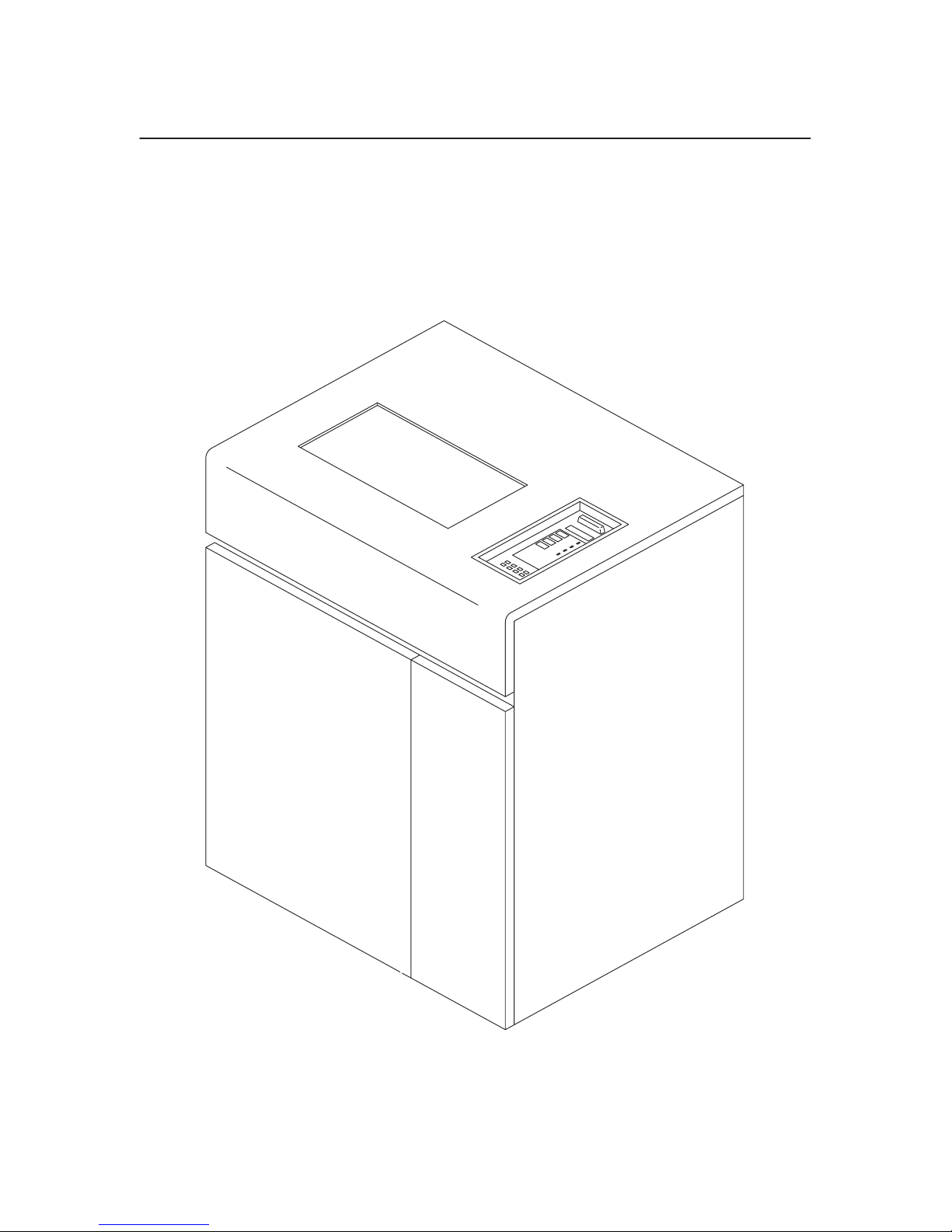
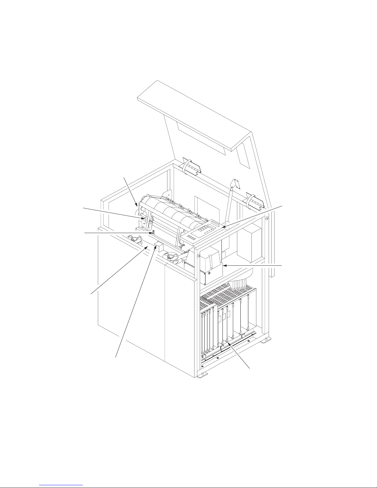
Description
The P9012 Printer (Figure 1–1) is a highly reliable, multi–function dot
matrix line printer. In addition to basic functions, the printer can produce
correspondence quality print for near letter quality (NLQ) printing
requirements, draft print for higher speed, and character attributes (dynamic
character generation) for wider application compatibility.
1–4
Figure 1–1. P9012 Printer
Overview
Page 11

Standard Features
• Extra Quiet Operation
• P–Series or Serial Matrix Protocols
• Raster Plot and Bit Image Graphics
• Dynamic Character Generation
Selectable Pitch Automatic Underline
Shadow Print Superscript Printing
Elongated Print Subscript Printing
Expanded Print
• Selectable Forms Length
• Nonvolatile Electronic Vertical Formatting
• Resident International Character Sets
• Resident OCR–A and OCR–B Character Sets
• Downloadable Character Sets
• Built–in Self–Tests and Diagnostics
• Configuration Printout
• Datastream Hex Code Printout
• Ribbon Fault Detector
• Resident Serial and Parallel Interfaces
Optional Features
• Intelligent Graphics Processing (IGP)
Forms Generation Reverse Image Printing
Bar Code Printing Logo Generation
Expanded Character Printing
• Additional Character Sets
• Downline Loadable Character Sets
• IBM Interfaces
3287 5225/5224
• Power Paper Stacker
• Dataproducts Long–Line Interface
Overview
1–5
Page 12
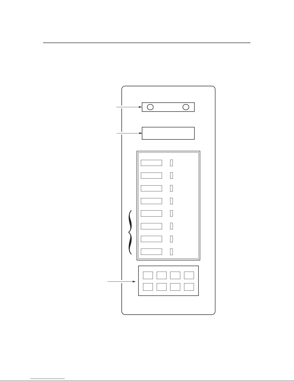
Control Panel Switches and Indicators
The P9012 operator control panel switches and indicators are illustrated in
Figure 1–2 and described in Table 1–1. Refer to the P9012 User’s Manual for
details on control panel operation.
Status Lamps
Message Display
These
switches are provided only if the
printer is equipped with an IBM 3287
interface.
These switches are visible only
with the printer cover open.
ON LINE
CLEAR
6/8 LPI
PAPER ADV
HOLD ENABLE
REPRINT
P
CANCEL PA2
MODE
ALT
MENU UP
MENU DOWN
ON LINE
CHECK
8 LPI
VFU LOADED
A1
NEXT
PREV
RUN/STOP
ENTER F/L
PRINT
MODE
Figure 1–2. Control Panel Switches and Indicators
1–6
Overview
Page 13

Table 1–1. Control Panel Switches and Indicators
Switch / Indicator Function
Except for ON LINE, all switches function only when the printer is off line.
Status lamps
Message display
ON LINE switch Press to place the printer on line or off line.
ON LINE indicator Illuminates when the printer is on line.
CLEAR switch
CHECK indicator Illuminates when a fault condition occurs.
6/8 LPI switch
8 LPI indicator Illuminates when line spacing is other than 6 lpi.
PAPER ADV
switch
VFU LOADED
indicator
Illuminate when the printer is on line, flash alternately to indicate a fault
condition, and remain off when the printer is off line.
Displays printer status and error messages.
Press to clear a fault indication after a fault has occurred. Press while in a
configuration menu to return the printer to the of
RUN/STOP at the same time to reset the printer.
Press to display and select the current line spacing.
Press momentarily to advance the paper one line. Press and hold to advance the
paper to the next top of form.
Illuminates when the format is being controlled by the vertical format unit.
f line state. Press CLEAR and
HOLD ENABLE
REPRINT PA1
CANCEL PA2
ALT MODE
switches
MENU UP switch Press to view the next menu or submenu. Press MENU UP and
MENU DOWN
switch
NEXT switch Press to display the next parameter and its current value in a configuration or
PREV switch
RUN/ST
OP switch Press to run and stop configuration and self tests. Runs and stops hex dump.
Used only if the printer is equipped with an IBM 3287 interface. For details,
refer to the
same time to lock or unlock the ENTER switch.
Press to view the previous menu or submenu. Press MENU DOWN and
at the same time to lock or unlock the ENTER switch.
diagnostic test menu.
Press to display the previous parameter and its current value in a configuration
or diagnostic test menu.
Press RUN/ST
PI 3287 Interface User’s Refer
OP and CLEAR at the same time to reset the printer.
ence Manual, P/N 108174–001.
(???)
at the
(???)
Overview
1–7
Page 14

Switch / Indicator Function
ENTER switch Press to enter a displayed parameter into the printer’s nonvolatile memory.
Must be unlocked before using, via the MENU UP or MENU DOWN switch.
PRINT MODE
switch
F/L switch Press to display and select the current forms length.
Press to display and select the current print mode.
Mechanical Controls
P9012 mechanical controls are described in Table 1–2 and illustrated in
Figure 1–3.
Table 1–2. Mechanical Controls
Item No.
(Figure 1–3)
1
Control or
Indicator Function
Forms Thickness
Adjustment Lever
Sets the platen for different thickness forms or paper. Open (raise)
fully for loading paper.
2
3 Horizontal
4 Tractor Lock (2) Locks tractors in position.
5 Vertical
6 Tractor (2) Used to set the left margin and paper width. The left tractor moves
Forms Thickness
Scale and Pointer
Adjustment Knob
Adjustment Knob
Indicates the relative thickness of forms or paper.
Allows fine positioning of the left print mar
slightly to the left or right.
Sets the top of form or first line to be printed. Rotate to move
paper vertically.
approximately one inch. The right tractor moves the full range.
gin. Moves paper
1–8
Overview
Page 15

1. Forms
2. Forms Thickness Scale/Pointer
3.
4. Tractor Lock (2)
5. V
6. Tractor (2)
Thickness Adjustment Lever
Horizontal Adjustment Knob
ertical Adjustment Knob
3
2
1
4
5
Overview
6
Figure 1–3. Mechanical Controls
1–9
Page 16
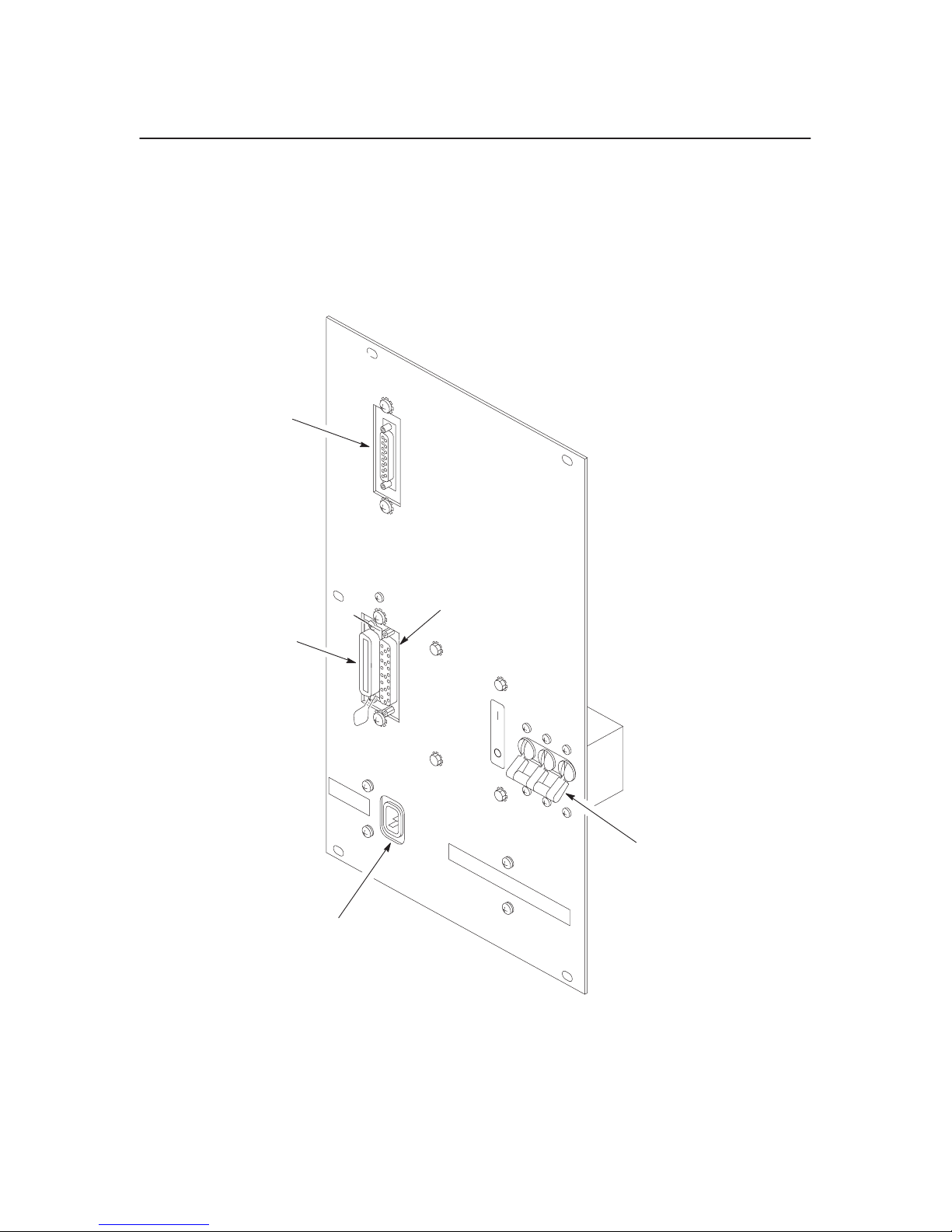
I/O Panel
The P9012 printer supports serial and parallel interfaces. Figure 1–4 shows
the I/O panel on the rear of the printer.
1. RS–232
2. AC On/Off Switch
3. AC Power Connector
4.
5.
1
4
5
Serial Connector
Dataproducts Parallel Connector
Centronics Parallel Connector
1–10
2
3
Figure 1–4. I/O Panel
Overview
Page 17
Tools, Test Equipment, and Supplies
The tools, test equipment, and supplies required for field level maintenance
of P9012 printers are listed in Table 1–3.
Table 1–3. Tools, Test Equipment, and Supplies
Item Part Number Recommended Item
Adjustable W
Diagonal Cutters
Digital Voltmeter — —
Extension, 3 in., 3/8 Drive — —
Feeler Gauge Set — Proto 000AA
Hammer Tip Alignment Tool 132266–001 —
Isopropyl Alcohol — —
Kimwipes — —
Lubricant 101805–001 —
Nut Driver Set — Xcelite P2120
Oscilloscope and Probes (≥35 MHz)
Pliers, Grip Ring — Truarc 1120
Pliers, Chain Nose
Ratchet, 3/8 in. Drive — —
Rule, Steel, 6 in. — General 616
Scale, Spring, 0 to 40 lbs. — —
Driver, Torque Screwdriver — Utica TS35
Adapter, Torque Screwdriver —
rench —
— Erem 91EH
— —
— Erem 11DH
Utica 91–4C
Utica HW–18
Extension, 6 in., Torque Screwdriver — —
Hex Bit, 3/16 in., Torque Screwdriver —
Hex Bit, 3/32 in., Torque Screwdriver —
Hex Bit, 5/32 in., Torque Screwdriver —
Hex Bit, 5/64 in., Torque Screwdriver — —
Screwdriver, Allen Hex — Xcelite 99PS40
Screwdriver, Phillips —
Screwdriver, Phillips —
Screwdriver, Slot —
Screwdriver, Slot —
Overview
Utica W–8
Utica HW–4
Utica HW–6
Xcelite X100
Xcelite X102
Xcelite A184
Xcelite R3164
1–11
Page 18

Item Recommended ItemPart Number
Shims, Counterweight 101564–001 —
Shims, Shuttle Assembly
Socket, 7/16 in., 3/8 in. Drive — —
Soldering Iron and Tips — —
X–acto Knife and Blades
103422–001 —
— —
1–12
Overview
Page 19

2
Chapter Contents
Principles of Operation
Scope 2–2. . . . . . . . . . . . . . . . . . . . . . . . . . . . . . . . . . . . . . . . . . . . . .
Purpose 2–2. . . . . . . . . . . . . . . . . . . . . . . . . . . . . . . . . . . . . . . . . . . .
Matrix Printing 2–3. . . . . . . . . . . . . . . . . . . . . . . . . . . . . . . . . . . . . .
Printer Functional Elements 2–9. . . . . . . . . . . . . . . . . . . . . . . . . . . .
Control Panel 2–12. . . . . . . . . . . . . . . . . . . . . . . . . . . . . . . . . . . . . . . .
Data Control Unit (DCU) PCBA 2–14. . . . . . . . . . . . . . . . . . . . . . . .
Mechanism Control Unit (MCU) PCBA 2–18. . . . . . . . . . . . . . . . . .
Mechanism Driver PCBA 2–22. . . . . . . . . . . . . . . . . . . . . . . . . . . . . .
Hammer Driver PCBA 2–25. . . . . . . . . . . . . . . . . . . . . . . . . . . . . . . .
Hammer Bank and Shuttle Mechanics/MPU 2–28. . . . . . . . . . . . . . .
Power Supply 2–30. . . . . . . . . . . . . . . . . . . . . . . . . . . . . . . . . . . . . . .
Ribbon Deck 2–32. . . . . . . . . . . . . . . . . . . . . . . . . . . . . . . . . . . . . . . .
Paper Feed Control Circuits 2–34. . . . . . . . . . . . . . . . . . . . . . . . . . . .
Platen Open/Paper Out Switches 2–36. . . . . . . . . . . . . . . . . . . . . . . .
Safety Circuits 2–37. . . . . . . . . . . . . . . . . . . . . . . . . . . . . . . . . . . . . . .
Normal Operation 2–38. . . . . . . . . . . . . . . . . . . . . . . . . . . . . . . . . . . .
Principles of Operation
2–1
Page 20

Scope
Purpose
This chapter presents the principles of operation for the P9012 printer. This
information is intended to provide the technician with a basic understanding
of printer functional operation.
This chapter also provides illustrations which show the location of test points
on the P9012 PCBAs.
For a complete list of signal mnemonics mentioned in this chapter, refer to
Appendix C.
The P9012 printer is a computer output device. It receives data from a host
computer and provides hard copy text or graphics. The hard copy is
composed of an array of dots. In the case of text, these dots are arranged in a
matrix to produce characters.
2–2
Principles of Operation
Page 21
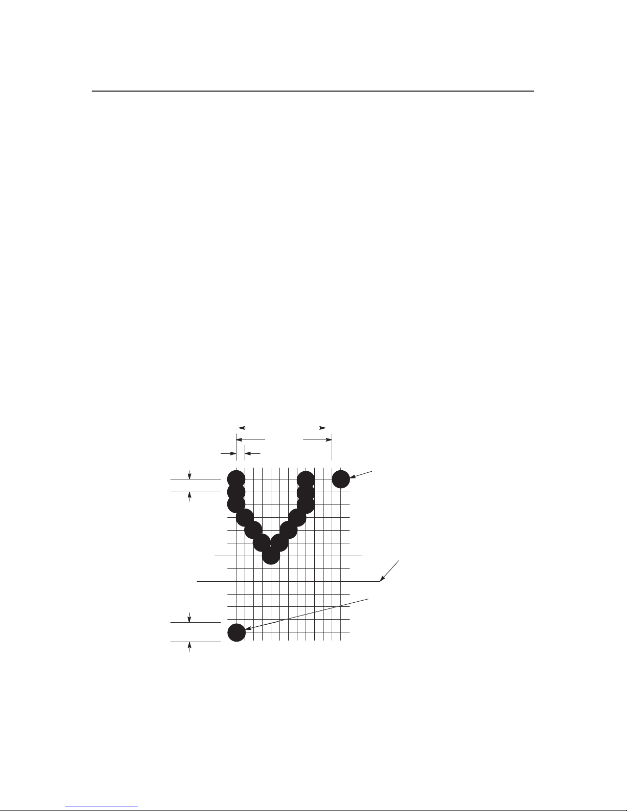
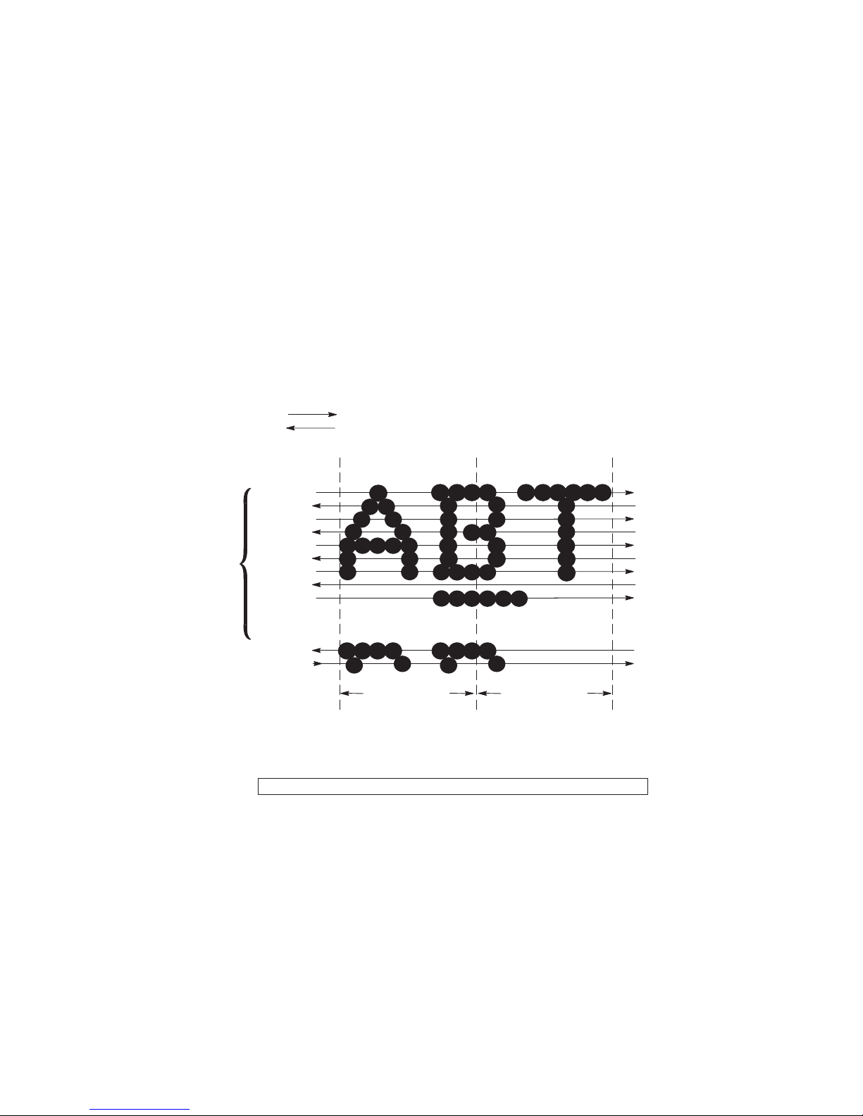
Matrix Printing
The Dot Matrix
In order to generate characters from dots, the dots must be arranged properly.
The imaginary grid on which the dots are positioned is referred to as the
matrix.
When in the data processing print mode, for spacing of six lines per inch
there are 12 dot rows from the top of one character line to the top of the next
(Figure 2–1 and Figure 2–2). With spacing of eight lines per inch there are
nine dot rows per character line, for nine lines per inch there are eight dot
rows per character line, and for spacing of ten lines per inch there are seven
dot rows per character line.
Elongated characters can be generated by printing each row twice, except for
the first and last (Figure 2–3).
0.01389
0.02
112COLUMN NO.
”
0.10
0.00835
”
”
”
Figure 2–1. Defining the Dot Matrix
FIRST ROW AND
COLUMN OF NEXT
CHARACTER
LOWEST
DESCENDER
LINE
DOT
FIRST ROW AND
COLUMN OF NEXT
CHARACTER LINE
6 LPI)
(AT
Principles of Operation
2–3
Page 22
UPPERCASE
(REFERENCE)
UNDERLINE
Figure 2–2. Typical Characters
LOWERCASE
WITH DESCENDER
PRINTED
WITH
UNDERLINE
WITH UNDERLINES
DOT COLUMN
13579
DOT ROW
1
2
’
2
3
’
3
4
’
4
5
’
5
6
’
6
7
7
’
8
’
8
9
UNDERLINE
WITHOUT
DOT ROW
1
2
’
2
3
’
3
4
’
4
5
’
5
6
’
6
7
UNDERLINES
DOT COLUMN
13579
2–4
Figure 2–3. Elongated Characters
Principles of Operation
Page 23
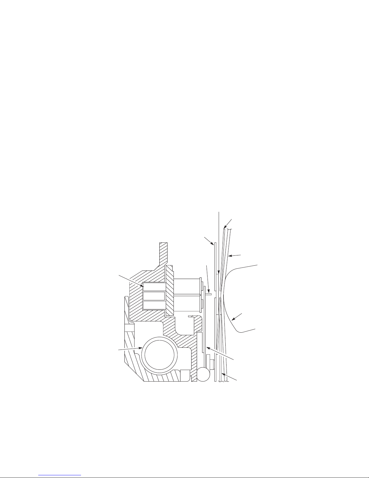
The Hammer Bank
In order to use matrix printing, you must have a method to print the required
dots. The P9012 uses the hammer bank.
The hammer bank contains a number of print hammers mounted on a shuttle
that can move back and forth horizontally. The shuttle prints a full line of
dots during each cycle of back and forth motion.
Each hammer consists of a stiff leaf spring attached at one end to the hammer
bank with a screw (Figure 2–4). The end opposite the screw has a pointed tip
attached. A permanent magnet keeps all the hammers retracted and under
tension. Each hammer has a magnetic coil which when energized counteracts
the permanent magnet, causing the hammer to release and strike the ribbon
and paper, leaving a dot (Figure 2–5). After printing, the rebounding hammer
is recaptured by the permanent magnet.
RIBBON
RIBBON MASK
MAGNET
SHUTTLE SHAFT
HAMMER BANK COVER
PAPER
HAMMER TIP
COIL
COIL
PLATEN
HAMMER SPRING
PAPER IRONER
Figure 2–4. Hammer and Shuttle Arrangement (Typical)
Principles of Operation
2–5
Page 24
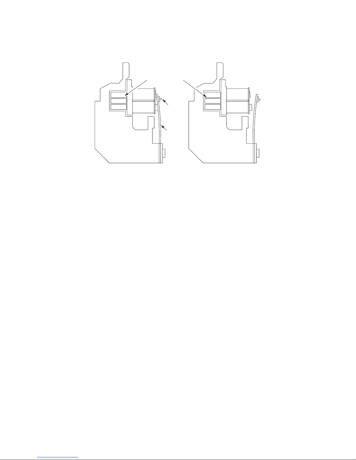
DE–ENERGIZED ENERGIZED
PERMANENT MAGNET
COIL
COIL COIL
NORMAL (RETRACTED) STATE ACTIVATED (RELEASE) STATE
HAMMER
TIP
HAMMER
SPRING
COIL
Figure 2–5. Print Hammer Action
2–6
Principles of Operation
Page 25
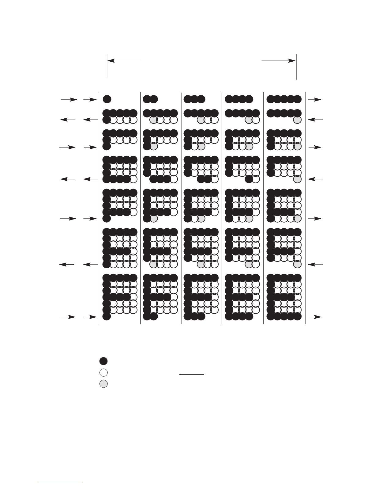
Character Generation
Paper advances one dot row after each shuttle cycle, causing the dot matrix
to be filled as required to generate each character (Figure 2–6 and
Figure 2–7).
DIRECTION OF SHUTTLE MOVEMENT
ONE
CHARACTER
ROW
DOT
ROW START
1
2
3
4
5
6
7
8
*
9
**
10
11
SPACE
12
1
2
1 HAMMER
PRINT SPAN
USED FOR LOWERCASE DESCENDER ONLY
*
USED FOR UNDERLINE AND LOWERCASE DESCENDER
**
NOTE:
The P9012 shuttle sweeps through 1.5 character positions at 10 cpi.
1 HAMMER
PRINT SPAN
PAPER
ADVANCES
PAPER
FEED
PAPER
ADVANCES
Figure 2–6. Standard Character Formation
Principles of Operation
2–7
Page 26
SHUTTLE
SCAN
DOT
* 1 * 1
ROW
SUCCESSIVE HAMMER STROKES PER SCAN
DOT COLUMN
*
1 3
5
* 1
3 5 7 1 3 5 7 9
* * 3
1
2
3
4
5
6
1
1
2
1
2
3
1
2
3
4
1
2
3
4
5
1
2
3
4
5
6
1
2
3
4
5
6
7
7
* EVEN COLUMN DOT CENTERS WITHIN THE PRINTED CHARACTER AREA
AND CHARACTER SPACE HAMMER POSITIONS ARE NOT ILLUSTRATED
IN THIS DIAGRAM.
NOTE: = DOT
= NO DOT WHERE HAMMER HAS BEEN
= HAMMER POSITION
Figure 2–7. Character Formation by One Hammer
2–8
Principles of Operation
Page 27

Printer Functional Elements (Figure 2–8 and Figure 2–9)
The printer is made up of the following functional elements:
• Control Panel
• Data Control Unit (DCU) PCBA
• Mechanism Control Unit (MCU) PCBA
• Mechanism Driver PCBA
• Hammer Driver PCBA(s)
• Hammer Bank and Shuttle Mechanics/Magnetic Pickup (MPU)
• Power Supply PCBA(s)
• Ribbon Deck
• Paper Transport
• Platen Open/Paper Out Switches
Figure 2–8 shows the basic interrelation of these elements and Figure 2–9 is
a simplified block diagram of the printer.
Principles of Operation
2–9
Page 28
TRACTOR
(Paper T
ransport)
PAPER OUT
SWITCH
RIBBON DECK
PLATEN OPEN SWITCH
CONTROL PANEL
SHUTTLE MOTOR
/ MPU
(Shuttle Mechanics)
HAMMER BANK / SHUTTLE
2–10
PCBAs
Figure 2–8. Printer Functional Elements
Principles of Operation
Page 29

SERIAL
HOST I/O
PARALLEL
DATA
CONTROL
STATUS
DATA
CONTROL
STATUS
CONTROL
PANEL
S
T
D
A
A
T
T
U
A
S
S
W
I
T
C
H
FAULT/STATUS
DCU MESSAGE
READY, READ
MESSAGE
BEEPER
DCU MCU
DO–D7
HSC
COM
+5V GND
MOTOR
CONTROL
FAULTS
SENSE
PM1–PM4
FROM P/SFROM MECH DRIVER
+36V GND –12V
MECHANISM
DRIVER
FAULT CIRCUITS
PAPER TRANSPORT
DRIVE
SHUTTLE DRIVE
RIBBON DRIVE
P/S CIRCUITS
+5V
–12V
+12V
GND
TO
DCU
AND
MCU
AC
POWER
120V
240V
50 or 60 Hz
–12V
GND
+12V
+5V
FROM MECH DRIVER
FROM P/S
POWER SUPPLY
+36V
GND
–12V
C
O
M
HAMMER
DRIVERS
HAMMER
+36V
GND
–12V
N
N
H
S
C
H
F
H
U
R
A
C
D
S
U
K
L
T
BANK
TO HAMMER DRIVER
AND MECH DRIVER
D
P
R
O
S
V
I
E
T
I
O
N
PAPER
DRIVE
STEPPER
MOTORDCMOTORDCMOTORS
SHUTTLE
DRIVE
I
S
E
N
S
E
RIBBON
DRIVE
FAULT
(IL/AIR)
BLOWER
ASSEMBLY
D
R
V
E
I
FAN
FAN
FAN
F
A
U
L
T
PLATEN
OPEN/
PAPER
OUT/
PAPER
MOTION
P
B
M
L
D
R
Principles of Operation
Figure 2–9. System Block Diagram
2–11
Page 30

Control Panel (Figure 2–10 and Figure 2–11)
The control panel consists of ten indicators, 16 momentary contact switches,
and an LCD alphanumeric display.
The control panel processes and sends switch closure information to the
DCU. It receives information on setting up the alphanumeric display as well
as status information. For a detailed discussion of panel operation, refer to
the P9012 User’s Manual.
Status Lamps
Message Display
These
switches are provided only
if the printer is equipped with an
IBM 3287 interface.
These switches are visible only
with the printer cover open.
ON LINE
CLEAR
6/8 LPI
PAPER ADV
HOLD ENABLE
REPRINT PA1
CANCEL
P
A2
ALT
MODE
MENU UP
MENU DOWN
NEXT
PREV
ON LINE
CHECK
8 LPI
VFU LOADED
RUN/STOP
PRINT MODE
ENTER F/L
2–12
Figure 2–10. Control Panel
Principles of Operation
Page 31

CONTROL PANEL ASSEMBLY
SW CLOSURES
STATUS
SWITCH CLOSURES
DATA
CONTROL PANEL PCBAPANEL DCU
CONTROL
Figure 2–11. Control Panel Block Diagram
Principles of Operation
2–13
Page 32

Data Control Unit (DCU) PCBA (Figure 2–12 and Figure 2–13)
The data control unit (DCU) PCBA begins the printing process by receiving
data through the host interface (J1, J2). Three interfaces are available on the
DCU card: the Centronics and Dataproducts parallel interfaces (J2), and an
RS–232 compatible serial interface (J1) running up to l9,200 baud. Protocols
are set up through the control panel.
In the parallel mode the input data is transferred directly via Direct Memory
Access (DMA) into memory. While in the serial mode, the input data is
entered into the input buffer with an interrupt–driven software routine. Once
the data is in the input buffer, as defined by software, the data is then taken
from the ASCII format to the format used in the dot image buffer (DIB).
Software determines the special character attributes and any special handling
of the data in the DIB due to the control characters.
The data is then loaded to the hammer driver card through the hammer load
circuit. The hammer load circuit is activated by the mechanism control unit
(MCU) pulling the NLOAD signal low. This signal interrupts the processor
at the highest level available. In this case the DCU is a slave to the MCU.
Control of the data transferred to the hammer drivers is done in the DCU. A
signal, NHMRBLK (hammer bank), loads all 0’s or non–printables to the
hammer driver card if asserted when the hammer load circuit is activated.
The DCU commands the MCU to drive all of the motors and other
mechanical interfaces. Print densities are transmitted to the MCU from the
DCU for proper MCU control of the mechanics.
2–14
Principles of Operation
Page 33

DCU PCBA
J1
Serial I/O
J2
Parallel I/O
(Slot 3)
J5
TP4 (+12VDC)
TP3 (–12VDC)
TP2 (VCCP5)
TP1 (GND)
Figure 2–12. Data Control Unit (DCU) PCBA
Principles of Operation
J6
2–15
Page 34

CLOCK
GENERATION
8/4/2 MHZ
NRST
2MHZ
RESET
GENERATION
370 ms
4MHZ
CLK
RESET
HALT
8MHZ
NMC
CLK
68000
CPU
ADDR
DATA
(23)
(16)
ADDRESS
DECODE
BUS
ARBITRATION
CONTROL
ADDRESS BUS
DATA BUS
EPROM
160K x 16
INTERFACES
HOST
RS–232
HOST
DATA
PRODUCTS
CEN–
TRONICS
HOST
RXD
DCD
DSR
CTS
TXD
RTS
DTR
REVCHNL
RX CLK
TX CLK
EXT CLK
GND
IDB8–IDB1
8
PI
IDSTB
IDRQ
IRDY
IONL
ICSTB
ICBUSY
IACK
ICPE
+5V
GND
NDAV
DSTBOUT
BAUD RATE
XTAL OSC
CLK INTA INTERRUPT
HOST SERIAL
AND INTERRUPT
CONTROLLER
(RS–232–DVRS/RCVRS)
PARALLEL
I/F
CONTROL
SIGNALS
DATA
LATCHING
CNTL
DTACK
H
O
S
T
D
M
A
INPUTS
68901
N
F
A
U
L
T
ERROR
CNTLS
DECODE
BUFFER
H
O
S
T
D
M
A
A
D
D
R
E
N
S
S
W
S
I
(18)
T
C
H
DMA HNDSHK
DTACK
GENERATOR
4MHZ
I/F
RR
I/O
POLARITY
IDS
PARITY CHECK
CONTROL CODE DETECT
DELETE CODE DETECT
OVERRUN DETECT
AND
RD
WR
INTA
SERIAL
AND
PARALLEL
I/F DMA
CONTROLLER
68B44
NLOAD
2MHZ
DMA
HNDSHK
BUS
ARBITRATION
ADDRESS BUS
DATA BUS
(16)
Figure 2–13. Data Control Unit (DCU) Block Diagram (1 of 2)
2–16
Principles of Operation
Page 35

MISC.
CONTROL
SIGNALS
J1
NLOAD
NVRAM
2K x 8
OE
ADDRESS
OUTPUT
STATUS
REGISTER
N
N
P
B
O
D
R
U
H
C
I
F
O
D
N
C
S
S
T
L
T
R
R
H
W
E
R
A
D
S
E
L
E
C
T
ADDRESS BUS (23)
DATA BUS
(16)
NSWITCH
FRONT
PANEL
I/F
LOGIC
ADDRESSABLE
LATCHES
A0,
– P/S
S/P
SHIFT REGISTER
NPFAULT
REGSEL
NENABLE
NSWITCH
NPCLK
NPLOAD
HAMMER DATA CONTROL
PARALLEL AND SERIAL I/O CONTROL
A1
MCU
I/O
(8)
PDATA
+5V
GND
J11
C
O
N
T
R
O
L
P
A
N
E
L
DOT
PLUCKER
MEMORY
CONTRLR
DRAM
256K X 16
Figure 2–13. Data Control Unit (DCU) Block Diagram (2 of 2)
+5VDC
+12VDC
–12VDC
GND
MCUFLT
MCUREC
NLOAD
COM
HSCK
MCU
HAMMER
DRIVER
MECH
DRIVER
Principles of Operation
2–17
Page 36

Mechanism Control Unit (MCU) PCBA (Figure 2–14 and Figure 2–15)
The mechanism control unit (MCU) PCBA controls the printer mechanism
through signals sent to the hammer driver and mechanism driver PCBAs.
The board is controlled by a microprocessor. It contains three sections of
memory, timers and control ports in order to control hammer firing, shuttle
motion, ribbon movement, and paper feed. It receives instructions and
commands from the DCU and communicates status and fault information
back to the DCU.
2–18
Principles of Operation
Page 37

TP3 (PPR BUSY)
TP4 (SDIR)
MCU PCBA
(Slot 4)
P7
TP1 (+5VDC)
TP2 (GND)
Figure 2–14. Mechanism Control Unit (MCU) PCBA
Principles of Operation
P8
2–19
Page 38

CLOCK
GENERATION
6/3 MHZ
RESET
GENERATION
750 ms
COMMAND PORT
4 X 8 MCU/R: DCU/W
4 X 8 DCU/R: MCU/W
H
(4)
A
M
M
E
R
D
R
I
V
(4)
E
R
I/O
(4)
N/A
(4)
CLK
3MHZ
RESET
MCU / DCU
DIP SWITCH
HAMMER
DRIVER
TEST PORT
HAMMER
DRIVER
STATUS PORT
COLOR
CONTROL
PORT
6MHZ
NRST
CLK
Z–80
CPU
BD0–7
BD0–7
D4–7
BD0–3
D0–7
ADDR
DATA
CNTL
(16)
(8)
–7
!/O AND
ADDRESS
DECODE
BUFFERED ADDRESS BUS
EPROM
36K X 8
BUFFERED DATA BUS
B
RD
U
F
CNTLS
DECODE
AND
BUFFER
D
0
Z–80 CTC
8254
TIMER
8254
TIMER
WR
INTA
CS
CS
CS
NUD/HRS
DCMOD
HAM
A0, A1
A0, A1
A0, A1
–7
F
E
R
E
D
D
A
T
A
B
U
S
D
0
B
U
F
F
E
R
E
D
A
D
D
R
E
S
S
B
U
S
MCU REC
D0–7
FIRE 0,1,2
(16)
(8)
DCU
I/F
COM
HSC
Figure 2–15. Mechanism Control Unit (MCU) Block Diagram (1 of 2)
2–20
Principles of Operation
Page 39

BUFFERED ADDRESS BUS
BUFFERED DATA BUS
SRAM
16K X 8
MCU REC
D0–7
DOT
COUNTER
STATUS
REGISTER
D0–3 D4–7
BD0–3
BD0–3
FIRE 0,1,2
PAPER FEED
FIRE
CONTROL
LOGIC
RIBBON
CONTROL
PF1/2
(4)
PF3/4
AIRFLT
IL
NFLT
NPLAO
NPADO
NRIBFLT
PMD
NHCK
NUD/HRS
FAULT
I/F
MECH
DRIVER
I/F
(3)
MECH
DRIVER
I/F
DCU I/F
HAMMER
DRIVER
I/F
HAM
COM
HSC
Figure 2–15. Mechanism Control Unit (MCU) Block Diagram (2 of 2)
Principles of Operation
DCMOD
MECH
DRIVER
I/F
2–21
Page 40

Mechanism Driver PCBA (Figure 2–16 and Figure 2–17)
The mechanism driver PCBA contains those circuits required to drive the
various motors of the printer mechanism. These driver circuits are under
control of the MCU. The mechanism driver PCBA also produces, by use of
switching regulators, the
DCU. These voltages are generated from the +36 V output of the power
supply. A 63 VDC power supply on the board is used in the paper feed motor
circuit and the shuttle motor circuit. Fault detect circuits monitor error
indications and sends a fault message flag to the MCU.
±12 V and +5 VDC required by the MCU and
2–22
Principles of Operation
Page 41

TP8 (PPF RAMP)
TP7 (+5V)
TP6 (+5 R
TP25 (+58V)
TN)
Mech Driver PCBA
TP11 (PF1 CHOP)
TP10 (VREF)
TP9 (PF2 CHOP)
(Slot 5)
Note:
TP23 (SHT PROP)
All voltages shown are in VDC.
TP22 (HES A)
J9
TP24 (SHT INTEG)
TP5 (+12V)
TP4 (+63V)
TP3 (+36V)
TP2 (MPU)
TP1 (PMD)
Principles of Operation
TP21 (HES RET/–12V)
TP13 (–12V)
J10
TP15 (–12V)
Figure 2–16. Mechanism Driver PCBA
2–23
Page 42

+36V
MCU
PCBA
FILE
MPU
+_
12VDC
IN
+5V IN
MASTER
CLEAR
RIB MOV
GUIDES
RIB TEN
PF1/PF2
NRUN1/NRUN2
PMD
NPAPO
NRIBFLT
NPLAO
DCMOD
NUPTOSPD
MPU PULSE
SHAPER
+_
12 VDC
POWER
SUPPLY
+5 VDC
POWER
SUPPLY
POWER UP
RESET
+36V
SWR
SWL
STEPPER MOTOR
+63VDC POWER
RIBBON
DC MOTORS
DRIVER
PAPER FEED
DRIVERS
SUPPLY
FAULT
DETECT
DC MOTOR
DRIVER
–12V +36V
MPU +
MPU –
+36VDC
+36V RTN
+5VDC
BRKRTRP
PMD
AMPLIFIER
DRIVE
SENSE
+58 VDC
REGULATOR
BLOWER
DRIVER
–12V +36V
BREAKER
TRIP
LEFT RIB. MTR
RIGHT RIB. MTR.
PAPER FEED
MOTOR
PAPER
MOTION DETECT
PAPER TRANSPOR T
RIBBON DRIVE
SHUTTLE MECHANICS
DC SHUTTLE
MOTOR
MAGNETIC
SENSOR
BLOWER
AC POWER
CIRCUIT
BREAKER
MECHANISM DRIVER PCBA
Figure 2–17. Mechanism Driver Block Diagram
2–24
GND +36 –12
Principles of Operation
Page 43

Hammer Driver PCBA (Figure 2–18 and Figure 2–19)
Each of the print hammers is controlled by electromagnetic coils, a driver,
and a logic circuit which, among other functions, controls the energizing of
the coils.
The hammer logic circuits perform the following functions:
• Convert serial data bits on the COM line into parallel data bits.
• Control the energizing of hammer coils to print dots in accordance with
the parallel data.
• Provide safety features to prevent coils from energizing under conditions
that could damage coils and hammer drivers.
• Provide an isolated and regulated +5 VDC supply, 5HL, for TTL logic
on the hammer driver PCBA.
Following a SYNC pulse, hammer shift clock (NHSC) pulses load data from
the COM DATA line into the hammer driver shift register. Every bit on the
COM line is clocked into the shift register by the rising edge of NHSC,
containing dot information for the characters to be printed by each hammer.
After the last bit is clocked into the shift register, the next SYNC pulse
causes hammer clock, NHCK, to load the contents of the shift register into
the data latches.
When a dot is to be printed, the data latch for that hammer is set and the
corresponding Darlington driver transistor is forward biased. At the same
time, the overdrive transistor is also forward biased for a period of time
controlled by the upper drive (NUD) signal from the MCU. During the
overdrive period, 48 volts are placed across the coils whose Darlingtons are
energized. After the NUD period is over, a –12V to ground current path
provides the current for the remainder of the hammers on time. This process
energizes the coil, releasing the hammer to print out.
Hammer reset signal, HRS, resets the output enable (OE) of the latch. The
latch output disables all Darlington drivers and deenergizes the coils. The
rebounding hammers are recaptured by the permanent magnet.
Principles of Operation
2–25
Page 44

TP10 (–8V)
TP1 (+5V)
TP7 (–12V)
TP8 (OD)
TP2 (COM1)
Hammer Driver PCBAs (1–3)
Note:
All voltages shown are in VDC.
TP3 (–HCK)
TP6 (+36V)
TP4 (NHSCB)
TP5 (–HRS)
TP9 (COMOUT)
2–26
Figure 2–18. Hammer Driver PCBA
Principles of Operation
Page 45

TEST
TIMING
+12V R
+5V
HMC
TN
–12V
+36V
MONITOR #1
HAMMER
DRIVER (H/D)
REGULATOR
Q
Q
FAULT
+5V
HAMMER
OUTPUT
DISABLE
CIRCUITS
5HL
SD
OD
OE
tt
tt
DARLINGTON DRIVERS (33)
tt
+36V
–12V
FAULT
MONITOR #2
NHCK
HRS
NUD
COM IN
NHSC
OPTO–
ISOLATORS
HCK
HRS
OD
COM IN
NHSC
D
CK
DATA
LA
TCHES (33)
SHIFT REGISTER (33)
CK
Q
OPTO–
ISOLATOR
Figure 2–19. Hammer Driver Block Diagram
COM OUT
Principles of Operation
2–27
Page 46

Hammer Bank and Shuttle Mechanics/MPU (Figure 2–20)
Hammer Bank Assembly/Shuttle
Operation of the hammer bank and shuttle is described on page 2–5.
Magnetic Pickup Unit (MPU)
Printing is synchronized with shuttle movement by the magnetic pickup
(MPU) signal. The magnetic pickup, located next to the flywheel timing disk,
is so oriented that timing signals relate precisely to the shuttle position.
Variations in magnetic reluctance are sensed by the magnetic pickup from
apertures on the timing disk as it rotates, generating SYNC pulses. Two
aperture locations at opposite ends of the disk are of double width (material
between two adjacent apertures is removed). These double width apertures
separate the 284 single width apertures into two groups and generate a
RESYNC signal coincident with the shuttle starting to move from left to
right.
Full rotation of the disk provides eight printing periods and four back and
forth shuttle cycles. Each printing period is followed by a turnaround period
when the shuttle movement is reversed, paper is advanced 0.0139 inches, and
no printing occurs.
The SYNC pulses are distributed to timers on the MCU.
The SYNC signal performs the following functions:
• Signals the MCU to load the hammer driver shift register for the next
hammer firing.
• Activates all hammers armed with a logic “1” during the previous load of
the hammer driver shift register by generating the NHCK signal.
• Initiates two time out periods which control the upper drive (NUD) and
the hammer reset signal (HRS). These signals activate and reset hammer
driver circuits previously activated by SYNC.
In the generation of SYNC and RESYNC signals, the roughly sinusoidal
output of the magnetic pickup is amplified and converted to a TTL
compatible square pulse by a circuit on the mechanism driver PCBA. The
2–28
Principles of Operation
Page 47

resulting MPU signal is synchronized with the timers (CLK) and applied to
print synchronizing logic on the MCU PCBA.
Typical signal levels received from the magnetic pickup are:
SYNC: 2.5 to 5.5 Vpp
RESYNC: 4 Vpp minimum
SHUTTLE MOTOR
(Shuttle Mechanics)
HAMMER BANK/SHUTTLE ASSEMBLY
Figure 2–20. Printer Functional Elements
MPU
Principles of Operation
2–29
Page 48

Power Supply (Figure 2–21)
The power supply PCBA is a switching power supply. Its regulated outputs
are –12 and +36 VDC. These voltages are supplied to the hammer driver and
mechanism driver PCBAs.
The printer contains three identical power supply PCBAs. Loading of the
PCBAs is such that some operation of the printer may be possible with an
inoperable power supply.
The required AC input line voltage for operation of the power supply is as
follows:
90 to 128 VAC, 49–51 and 59–61 Hz
190 to 256 VAC, 49–51 Hz
If the AC input voltage is removed from the power supply, during either
normal operation or an overload condition, the power supply will recover so
that power may be reapplied in less than 2.5 seconds. If an overload occurs,
the power supply will return to the normal operation less than 8 seconds after
the fault is cleared.
The performance characteristics of the power supply are as follows:
–12 VDC supply, –12.8 V output voltage, ±10%
+36 VDC supply, +36 V output voltage, ±10%
Note that the 12V load includes 60,000 mfd of filter capacitors and is
considered a part of the power supply output filter.
NOTE: As shown in Figure 2–21, the power supply contains a jumper that
must be configured for the type of P9012 printer in use. For printers
that contain an Autotap board, place the jumper in the “SHORT”
position. For printers that do not contain an Autotap board, place the
jumper in the “OPEN” position.
2–30
Principles of Operation
Page 49

Power Supply PCBAs (1–3)
SHORT
OPEN
Principles of Operation
Figure 2–21. Power Supply PCBA
2–31
Page 50

Ribbon Deck (Figure 2–22 through Figure 2–24)
The ribbon deck assembly contains two dc servomotors that move the ribbon
continuously while there is shuttle action. One motor acts as the driver,
drawing the ribbon against opposing torque exerted by the other motor.
When a length of metal tape at either ribbon end is detected by the ribbon
guide at either side of the shuttle, the two motors exchange roles and ribbon
travel is reversed. This system maintains a relatively constant ribbon speed
and tension.
The ribbon moves only while the shuttle is in motion. When the printer is on
and no faults have occurred, the ribbons will be tensioned by the application
of NRIBEN from the MCU PCBA. When NRIBMOV is applied, the ribbon
will move. NRIBMOV is applied when DCMOD comes on starting the
shuttle.
The NRIBMOV and NRIBEN signals enable gates which control power to
the ribbon drive motors.
When an end of ribbon sensor is activated, the corresponding latch turns on
the related FET.
NRIBENMOV
NRIBEN
RIGHT
DETECTOR
LEFT
DETECTOR
When the right end of the ribbon is detected, the latch is set to the opposite
state and the motors reverse roles.
When the shuttle motor is not running, that is, DCMOD not modulating and
NRIBMOV is high, both FETs are held off and the motors act in opposition,
as the voltage provides feedback to resist ribbon movement, provided
NRIBEN is not deactivated by a printer fault.
+36V
RIBBON
DIRECTION
CONTROL
+5V
RIBBON
DC MOTOR
DRIVERS
M
M
Figure 2–22. Ribbon Deck Block Diagram
2–32
Principles of Operation
Page 51

+5V
Figure 2–23. Ribbon Deck
+27V
+17.8V
K1
M1
R
F1
M2
+1V
TO +5V
R
+5V++
K2
––
F2
+36V
NSD
RH
END OF
RIBBON
DETECTORS
LATCH
LH
Figure 2–24. Ribbon Control PCBA Simplified Schematic
Principles of Operation
+5V
R
IN1
+3.7V +5V
Q1 Q2
R
S1
(LOW)
(HIGH)
R
C
(VOLTAGES ARE AS INDICATED
WHEN RIBBON IS RUNNING FROM
R
R
RIGHT
IN2
S2
TO LEFT)
2–33
Page 52

Paper Feed Control Circuits (Figure 2–25 and Figure 2–26)
The paper feed motor contains two pairs of coils, driven in sequence. As the
electromagnetic detent locking the rotor is released, the rotor is advanced one
increment, and the detent is set again. One pair of coils is driven by the
push–pull signal, PFM1/PFM2, and the other pair by PFM3/PFM4.
The drive signals are controlled by the four phase paper feed signals, PF1,
PF2, NRUN1, and NRUN2 generated in paper feed logic. Each pair of
PF1/PF2/NRUN1/NRUN2 pulses increments the motor one step to advance
paper 1/288 inch.
When paper is to be advanced either to the next character line, to the top of
form, to a selected vertical tab or by being put under EVFU control, the
corresponding profile of paper movement velocity is selected by the MCU to
obtain precise paper control. Paper is accelerated at a variable rate to
optimize both speed and precision and decelerated at a variable rate that
prevents overshoot. To achieve this modulated paper movement, paper feed
logic generates PF1, PF2, NRUN1, and NRUN2 regulated by the velocity
profile software.
NRUN1/PF1
NRUN2/PF2
NRUN1/PF1 and NRUN2/PF2 each drive identical independent control
circuits. Either circuit operates when the paper feed pulse passes through
gates and drives a push–pull current amplifier circuit that provides drive
current to one pair of motor coils.
CURRENT
DRIVER
CURRENT
DRIVER
PFM1
PFM2
TO PAPER
FEED MOTOR
PFM3
PFM4
Figure 2–25. Paper Feed Control Circuits Block Diagram
2–34
Principles of Operation
Page 53

TRACTORS
(PAPER TRANSPOR T)
PAPER FEED MOTOR
Principles of Operation
Figure 2–26. Paper Feed Components
2–35
Page 54

Platen Open/Paper Out Switches (Figure 2–27)
These switches signal the mechanism driver that the printer is out of paper or
the platen has been left open. When either signal is detected, paper transport
is disabled and the ribbon loses tension. The signal faults are reported to the
control panel from the MCU to the DCU.
2–36
PLATEN OPEN SWITCH
PAPER OUT SWITCH
Figure 2–27. Platen Open/Paper Out Switches
Principles of Operation
Page 55

Safety Circuits (Figure 2–28)
Excessive current and overheating can damage coils and hammer drivers in
either of the following situations:
• Current turned on when not needed to release hammer springs.
• Current left on after hammer spring release.
Three safety circuits on the hammer driver board prevent excessive current
by disabling the latch output drivers under control of the OE signal. For each
of the following three conditions, OE is held low:
• +5VHL supply out of tolerance — when the +5VHL voltage output
exceeds Zener diode avalanche levels, OE is held low.
• –12V, +36V supply ground missing — if the –12V, +36V return is not
connected to the hammer driver board, the OE line is held low.
• +5V, –12V voltages levels are out of tolerance.
Two other circuits monitor the leakage currents of both the overdrive
transistor and the lower hammer driver transistors and if the currents are too
large, the fault circuit signals the MCU which in turn turns off the printer via
BRKRTRIP.
A fourth safety circuit halts hammer firing in the event of a hammer master
clear, HMC, or the loss of the hammer reset pulse, HRS. When HMC is low,
the output of the one millisecond one–shot, U16, is normally kept high while
being triggered by HRS pulses. Whenever HRS pulses stop or HMC goes
high, the one–shot resets within one millisecond and hammer firing stops.
NORMALLY HIGH
GOES LOW FOR HMC
OR LOSS OF HRS PULSES
+5VHL
HRS
HMC
3
4
1
2
4
U16
3
1 MILLISECOND
2
ONE – SHOT
1
Q
Q
8
SD
HRS
OE
Figure 2–28. Safety Circuits
Principles of Operation
2–37
Page 56

Normal Operation (Figure 2–29)
Character Printing
During one cycle of normal operation, the printer is set up and put online by
the operator, using the control panel. Host computer data is then read into the
data input buffer. ASCII data from the input buffer is compared to tables
stored in memory to determine the matrix locations to be printed for each
character and build the dot image buffer. Information from the dot image
buffer is synchronized with printer requirements using the magnetic pickup
signal then shifted out to hammer drivers. The selected hammers are fired.
When all dots in a row are printed, the paper is shifted one dot row and the
next dot row of data from the dot image buffer is synchronized then shifted
out to the hammer driver. Shifting of paper is delayed to allow double
printing when adjacent dot printing is required.
Self–Test
During self–test, internally generated data is used to build the dot image
buffer. Operation then proceeds as in normal printing.
2–38
Principles of Operation
Page 57

FRONT PANEL
PRINTER SETUP
PRINTER ENABLE
HOST
CONNECTION
INPUT DATA
THROUGH DMA CONTROLLER
SELF–TEST
SELECT FROM
FRONT
P
68B44
(DCU)
ANEL
(DCU)
SOFTWARE
INPUT DATA
BUFFER
(IN DYNAMIC RAM)
ASCII DATA (DCU)
BUILD DOT IMAGE BUFFER (DIB)
FROM LOOK UP
PUT INTO DYNAMIC RAM (DCU)
SYNCHRONIZE THE TIMING TO
THE CODE WHEEL (MPU)
SOFTWARE (MCU)
DEMAND HAMMER LOAD (MCU)
DATA SHIFTED OUT
TABLES IN FONT
TO HAMMER DRIVER (DCU)
(DCU)
CONTROLLED BY SOFTWARE
EXECUTED BY HARDWARE
CONTROLLED BY SOFTWARE
EXECUTED BY HARDWARE
Principles of Operation
FIRE HAMMERS
ON NEXT MPU
ALL DOTS IN ROW PRINTED ?NY MOVE
(MCU)
SOFTWARE TIMERS
SOFTWARE DECISION
Figure 2–29. Operation Flow Diagram
PAPER
(MCU/MECH
DRIVER)
2–39
Page 58

2–40
Principles of Operation
Page 59

3
Chapter Contents
Scheduled Maintenance
Preventive Maintenance Checks and Services (PMCS) 3–2. . . . . . .
Inspecting the Printer 3–3. . . . . . . . . . . . . . . . . . . . . . . . . . . . . . . . .
Cleaning the Printer 3–4. . . . . . . . . . . . . . . . . . . . . . . . . . . . . . . . . .
Scheduled Maintenance
3–1
Page 60

Preventive Maintenance Checks and Services (PMCS)
Perform Preventive Maintenance Checks and Services (PMCS) every three
months or after every 250 hours of operation, whichever comes first.
Do these checks more often if the printer is used for heavy–duty, continuous
printing or if it is located in a dusty area.
PMCS are listed in Table 3–1.
WARNING
Disconnect the AC power cord before performing PMCS. Failure to do
so could result in injury to you or damage to the equipment.
Table 3–1. Preventive Maintenance Checks and Services
Interval Assembly Procedure Page
Every 3 months or 250 hours
of operation, whichever
occurs first.
Printer
Printer
Shuttle Belt
Paper Feed Belt
Inspect the printer.
Clean the printer.
Check tension.
Check tension.
3–3
3–4
5–24
5–26
3–2
Scheduled Maintenance
Page 61

Inspecting the Printer
Visually inspect the printer using Table 3–2 as a guide. Correct any condition
found during inspection that could affect printer performance or reliability.
Item(s) to Inspect Procedure
Table 3–2. Physical Inspection
Cabinet, base, frame
Attaching hardware Inspect fasteners for thread damage, rust, or corrosion.
Nameplates Inspect for legibility and damage.
Printer cover, cabinet door(s),
damper/struts
Hinges Inspect for damage and loose or missing hardware.
Electrical connectors Inspect for damage and bent or broken pins.
Controls and indicators
Windows Inspect for breaks, cracks, or discoloration.
Ribbon cables
Circuit boards Inspect for breaks, warpage, and evidence of overheated
Check for damage, cracks, breaks, dents, gouges, scratches,
warpage, rust, corrosion, and proper finish.
Inspect for damage and loose or missing hardware. Check that the
door(s) open/close without binding and stay closed. Check that
the printer cover opens/closes smoothly and damper/struts hold
cover open.
Inspect for damage.
Inspect for broken wire or strands, damaged insulation, pinched
wiring, and possible shorting conditions.
components. Some printer disassembly is required. See Chapter 6,
Replacement Procedures.
Fans and motors
Flywheel cam, Shuttle and
Counterweight cam followers
Scheduled Maintenance
Inspect for obvious damage. Some printer disassembly is
required. See Chapter 6, Replacement Procedures.
After checking belt tension, inspect the cam and follower surfaces
for excessive wear or damage. If required, replace the parts as
described in Chapter 6, Replacement Procedures.
3–3
Page 62

Cleaning the Printer
Do not use abrasive cleaners, particularly on the window. Do not drip
water into the printer; damage to equipment will result. When using
spray solutions, do not spray directly onto the printer; spray the cloth.
Exterior of Cabinet
1. Wipe the cabinet with clean, lint–free cloth dampened (not wet) with
water and mild detergent or window cleaning solution.
2. Dry the cabinet with a clean, lint–free cloth.
3. Vacuum the ventilation slots at the sides of the cabinet.
Interior of Cabinet (Figure 3–1)
CAUTION
1. Set the AC power switch on the rear of the printer to the O (OFF)
position.
2. Disconnect the the AC power cord from the rear of the printer and open
the top cover.
3. Move the forms thickness adjustment lever (1) to the fully–open
position.
4. Remove paper from the printer.
5. Squeeze the lock tabs (2) and lift the ribbon spools (3) from the ribbon
hubs (4).
6. Using a soft–bristled brush, wipe off paper dust and ribbon lint. Vacuum
up the residue. Pay particular attention to the tractors (5), hammer bank
(6), and base casting (7).
7. Wipe the splined shaft (8) with a soft cloth.
8. Using a cloth dampened with alcohol, clean the ribbon guides (9).
3–4
Scheduled Maintenance
Page 63

1. Forms
2. Lock T
3.
4.
5. Tractor (2)
6.
7.
8.
9.
10.
11.
12.Platen
Thickness Adjustment Lever
ab (2)
Ribbon Spool (2)
Ribbon Hub (2)
Hammer Bank
Base Casting
Splined Shaft
Ribbon Guide
Paper Motion Detector
Ribbon Path
3
5
11
6 (under cover)
12
10
1
2
4
8
9
7
Figure 3–1. Cleaning Interior of Cabinet
Scheduled Maintenance
3–5
Page 64

9. Open the left tractor (5) and clean the paper motion detector (10) with a
soft brush.
10. Clean the ribbon path (11) with a soft brush.
11. Inspect the platen (12). If necessary, wipe with a cloth dampened with
alcohol to remove ink or dirt.
12. Vacuum dust or residue that has accumulated inside the lower cabinet.
13. Wipe the lower cabinet interior with a clean, lint–free cloth dampened
with water and mild detergent or window cleaning solution.
Hammer Bank Assembly (Figure 3–2)
1. Remove the power cord from the rear of the printer and open the top
cover.
2. Raise the forms thickness adjustment lever (1) to fully open. Remove
any paper present.
3. Squeeze the lock tabs (2) and remove the ribbon spools (3) from the
ribbon hubs (4). Slide the right tractor (5) fully to the right.
4. Remove the ribbon deck (6) as described on page 6–8 of Chapter 6,
Replacement Procedures. This will provide access to the hammer
bank (7).
5. Push the top edge of the ribbon mask (8) on the hammer bank cover
assembly (9) toward the platen (10) and hold.
CAUTION
Exercise care when handling the ribbon mask; damage can affect print
quality.
6. Use a stiff, nonmetallic bristle brush to remove ribbon lint and paper dust
from the hammer springs (11) and tips (12) and from the ribbon mask,
especially in the ribbon path. Vacuum loosened particles. Remove
stubborn accumulations using a cloth or Kimwipe moistened (not wet)
with isopropyl alcohol.
7. Return the ribbon mask to the operating position.
3–6
Scheduled Maintenance
Page 65

5
1
3
2
10
4
1. Forms
2. Lock T
3.
4.
5.
6. Ribbon Deck
7.
8.
9. Hammer Bank Cover
10.Platen
11.
12.
Thickness Adjustment Lever
ab (2)
Ribbon Spool (2)
Ribbon Hub (2)
Right T
ractor (6)
Hammer Bank
Ribbon Mask
Hammer Springs
Hammer T
ips
6
8
9
11
12
7
Figure 3–2. Cleaning Hammer Bank Assembly
Scheduled Maintenance
3–7
Page 66

8. Install the ribbon deck as described on page 6–8 of Chapter 6,
Replacement Procedures.
9. Install the ribbon spools on the ribbon hubs. Replace paper.
10. Close the cover and return the printer to normal operation.
3–8
Scheduled Maintenance
Page 67

4
Chapter Contents
Troubleshooting
Introduction 4–2. . . . . . . . . . . . . . . . . . . . . . . . . . . . . . . . . . . . . . . . .
Fault Messages 4–2. . . . . . . . . . . . . . . . . . . . . . . . . . . . . . . . . . . . . .
Symptoms Not Indicated by Fault Messages 4–11. . . . . . . . . . . . . . .
Diagnostic Self–Tests 4–14. . . . . . . . . . . . . . . . . . . . . . . . . . . . . . . . .
Running the Self–Tests 4–16. . . . . . . . . . . . . . . . . . . . . . . . . . . . . . . .
Hex Code Printout 4–17. . . . . . . . . . . . . . . . . . . . . . . . . . . . . . . . . . . .
Troubleshooting
4–1
Page 68

Introduction
This chapter contains procedures for troubleshooting printer malfunctions.
You must operate the printer to check printer performance after correcting
problems, so have the User’s Manual at the printer site. Although diagnostic
self–test procedures are covered in this chapter, basic printer operation is not
covered.
Fault Messages
If a fault condition occurs in the printer, the CHECK light illuminates, the
status lamps blink alternately, and the first line of the message display
indicates “FAULT CONDITION.” If configured, an alarm sounds when the
Fault Condition occurs. The second line of the display indicates the specific
fault.
NOTE: The alarm can be turned off before the fault is cleared by pressing
the CLEAR switch.
There are two types of displayed faults:
• Operator correctable
• Field–service required, indicated by an asterisk (*) next to the fault
message
When troubleshooting a fault message, always perform the following
procedure first:
1. Press the CLEAR switch. If the printer displays “OFFLINE READY”
after a few seconds, the message was a false indication. Return the
printer to normal service.
2. If the fault message reappears after pressing CLEAR, turn printer power
off, wait five seconds, and turn power on. If the message reappears, find
the applicable message on one of the following pages, and perform the
checks and corrective actions listed.
4–2
Troubleshooting
Page 69

Test the printer after each corrective action. Stop maintenance when the
symptom disappears. Always press the CLEAR switch after correcting a
fault indicated by a fault message.
Operator Correctable Faults
Printer problems that the operator can correct are self–explanatory and
appear on the second line of the display:
CHANGE RIBBON PLATEN OPEN
COOLING RIBBON
PAPER JAM SHUTTLE STALL
PAPER OUT STACKER
After correcting an operator correctable fault, press the CLEAR switch
before placing the printer on line. If any other fault messages appear without
an asterisk (*), press the CLEAR switch to continue. However, if this
problem persists, contact the customer service representative (CSR) to
correct the problem.
IMPORTANT
IMPORTANT
If NVM INITIALIZED PRESS CLEAR appears on the display every
time the printer power is cycled, non–volatile memory must be replaced.
Non–volatile memory can be temporarily bypassed by pressing the
CLEAR switch. However, no configuration data will be saved, and the
factory default is loaded. Contact the customer service representative to
correct the fault.
Troubleshooting
4–3
Page 70

Field Service Required
Printer problems requiring the attention of the customer service
representative also appear on the second line of the display and are indicated
by an asterisk (*) next to the message:
FONT PROM *
HAMMER DR PCB X * ( X = 1, 2, or 3 )
NOVRAM *
PROGRAM PROM *
If HAMMER DR PCB X * appears on the display, printer power will
automatically shut off 10 seconds after the fault message is displayed.
If, upon printer power–up, the lamps and/or LEDs flash and no message is
provided in the display, contact the customer service representative to correct
the fault.
4–4
Troubleshooting
Page 71

CHANGE RIBBON
Instruction Indication Yes No
1. Check for fault message
when using the
RibbonMinder feature.
COOLING
Instruction Indication Yes No
1. Check for inoperative blower
assembly, air flow sensor, or
MCU PCBA.
CHANGE RIBBON
message.
COOLING message. Replace one at a
Replace the
ribbon.
time, in the
following order,
until the message
disappears:
mechanism driver,
MCU PCBA,
sensor, blower.
—
—
FONT PROM *
Instruction Indication Yes No
1. Set power switch to O (OFF).
Wait 5 seconds. Set power
switch to 1 (ON).
2. Press the CLEAR switch. FONT PROM *
3. Run a diagnostic self–test
(page 4–14).
FONT PROM *
message.
message.
FONT PROM *
message.
Step 2. Return printer to
normal operation.
Step 3. Return printer to
normal operation.
Replace all font
PROM chips on
the DCU PCBA.
Return printer to
normal operation.
Troubleshooting
4–5
Page 72

HAMMER DR PCB X *
Instruction Indication Yes No
1. Set power switch to O (OFF).
Wait 5 seconds. Set power
switch to 1 (ON).
2. Press the CLEAR switch. HAMMER DR PCB X *
3. Run a diagnostic self–test
(page 4–14).
4. Run a diagnostic self–test
(page 4–14).
HAMMER DR PCB X *
message.
message.
HAMMER DR PCB X *
message.
HAMMER DR PCB X *
message.
Step 2. Return printer to
normal operation.
Step 3. Return printer to
normal operation.
Replace the
hammer driver
PCBA (page
6–74) and go to
step 4.
NOTE: X = PCBA
1, 2, or 3. #1
controls hammers
60–88; #2 controls
30–60; #3 controls
1–30.
Replace one at
time until the
message
disappears: power
supply PCBA
(page 6–74) or
shuttle assembly
(page 6–18).
Return printer to
normal operation.
Return printer to
normal operation.
NOVRAM *
Instruction Indication Yes No
1. Set power switch to O (OFF).
Wait 5 seconds. Set power
switch to 1 (ON).
2. Press the CLEAR switch. NOVRAM * message. Step 3. Return printer to
3. Cycle power. NOVRAM * message. Replace the
4–6
NOVRAM * message. Step 2. Return printer to
normal operation.
normal operation.
Return printer to
non–volatile RAM
chip on the DCU
PCBA.
normal operation.
Troubleshooting
Page 73

PAPER JAM
Instruction Indication Yes No
1. Inspect paper path for
bunched, torn, folded paper
or labels.
2. Inspect the narrow
passageway between the
face of the platen and the
ribbon mask for bits of torn
paper or ribbon lint. Check
the holes in the ribbon mask
surrounding each hammer
tip.
3. Check that the ribbon mask
has not been deformed in
such a way as to block the
paper path.
4.
Load paper
feeds and run a diagnostic
self–test (page 4–14).
5. Set the paper motion sensor
fault setting to DISABLE. See
the
6. Check paper feeding as the
printer prints.
. Do some line
P9012 User’s Manual
.
Paper path is clear. Step 2. Remove paper
and go to step 2.
Debris found. Gently remove
paper or lint
particles with a
wooden stick or
pair of tweezers.
CAUTION: Do not
pry or apply force
to the hammer
tips. Go to step 3.
Ribbon mask damaged
or bent.
PAPER JAM message. Clean the paper
PAPER JAM message. Return printer to
PAPER JAM message. Check the tractors
Replace the
hammer bank
cover assembly.
Go to step 4.
motion detector
with cotton swab.
Go to step 7.
and spring behind
the tractor door.
Replace the
mechanism driver
(page 6–72).
Step 3.
Step 4.
Return printer to
normal operation.
normal operation.
Return printer to
normal operation.
7. Run a diagnostic self–test
(page 4–14).
8. Check the platen gap
adjustment (5–18).
9. Check for damage to the
paper feed motor or belt.
10. Run a diagnostic self–test
(page 4–14).
Troubleshooting
PAPER JAM message. Replace paper
motion sensor
assembly (page
6–62). Go to step
8.
Platen gap incorrect. Adjust the platen
gap until it is
within spec and
the message
disappears. Go to
step 9.
Paper feed motor or
belt damaged.
PAPER JAM message. Replace the MCU
Replace the paper
feed motor (6–56)
or belt (6–52). Go
to step 10.
PCBA (page
6–72).
Return printer to
normal operation.
Return printer to
normal operation.
Return printer to
normal operation.
Return printer to
normal operation.
4–7
Page 74

PAPER OUT
Instruction Indication Yes No
1. Load paper. — Step 2. —
2. Run a diagnostic self–test
(page 4–14).
PAPER OUT
message.
Replace paper out
switch assembly
(page 6–66).
Return printer to
normal operation.
PLATEN OPEN
Instruction Indication Yes No
1. Load paper. — Step 2. —
2. Close forms thickness
adjustment lever.
3. Run a diagnostic self–test
(page 4–14).
PLATEN OPEN
message.
— Step 3. —
Replace platen
open switch
assembly (page
6–68).
Return printer to
normal operation.
4–8
Troubleshooting
Page 75

PROGRAM PROM *
Instruction Indication Yes No
1. Set power switch to O (OFF).
Wait 5 seconds. Set power
switch to 1 (ON).
2. Press the CLEAR switch. PROGRAM PROM *
3. Run a diagnostic self–test
(page 4–14).
PROGRAM PROM *
message.
message.
PROGRAM PROM *
message.
Step 2. Return printer to
normal operation.
Step 3. Return printer to
normal operation.
Replace the
program PROM
chips on the DCU
PCBA.
Return printer to
normal operation.
RIBBON
Instruction Indication Yes No
1. Wind the ribbon by hand and
check for folds, tears, holes,
fraying.
2. Install a new ribbon. — Step 3. —
Ribbon damaged. Step 2.
If folded but
otherwise okay,
rewind and
reinstall the
ribbon.
3. Run a diagnostic self–test
(page 4–14).
RIBBON message. Replace one at a
time until the
message
disappears: ribbon
control PCBA
(page 6–10),
mechanism driver,
or MCU PCBA
(page 6–72).
Return printer to
normal operation.
Troubleshooting
4–9
Page 76

SHUTTLE STALL
Instruction Indication Yes No
1. Check that forms thickness
adjustment lever is not
closed too tightly; this can
jam the ribbon and shuttle.
2. Run a diagnostic self–test
(page 4–14) and check for
shuttle obstruction.
3. Check the magnetic pickup
sensor for proper gap and
output (page 5–20), and a
broken or loose connector.
4. Run a shuttle/ribbon test. SHUTTLE STALL
5. Check for a broken or
damaged shuttle belt.
6. Run a shuttle/ribbon test. SHUTTLE STALL
Forms thickness
adjustment lever is set
correctly.
SHUTTLE STALL
message.
SHUTTLE STALL
message.
message.
Belt is damaged. Replace the
message.
Step 2. Readjust the
setting of the
forms thickness
adjustment lever.
Go to step 2.
Remove the
obstruction and go
to step 3.
Replace the MPU
(page 6–42). Go
to step 4.
Step 5. Return printer to
shuttle belt (page
6–48). Go to step
6.
Replace one at a
time until the
message
disappears:
mechanism driver,
MCU, or DCU
PCBA (page
6–72). Go to step
7.
Return printer to
normal operation.
Return printer to
normal operation.
normal operation.
Step 6.
Return printer to
normal operation.
7. Run a shuttle/ribbon test. SHUTTLE STALL
message.
8. Run a shuttle/ribbon test. SHUTTLE STALL
message.
STACKER
Instruction Indication Yes No
1. Check for proper paper
stacking when using the
power paper stacker.
4–10
STACKER message. Clear the paper
Replace the
shuttle motor
(page 6–44) and
go to step 8.
Replace the
shuttle assembly
(page 6–18).
exit path.
Return printer to
normal operation.
Return printer to
normal operation.
Return printer to
normal operation.
Troubleshooting
Page 77

Symptoms Not Indicated by Fault Messages
Troubleshoot malfunctions not indicated by fault messages using standard
fault–isolation techniques:
1. Debrief the operator for a general description of the problem.
2. Verify the fault by running diagnostic self–tests or replicating conditions
reported by the user.
3. Locate the malfunction using the half–split method:
a. Isolate faults to half the remaining system at a time, until the
final half is a field–replaceable part or assembly. (Chapter 6 lists
all field–replaceable assemblies.)
b. Start at a general level and work down to details.
4. Replace the defective part or assembly.
IMPORTANT
Do not attempt field repairs on electronic components or assemblies —
replace the entire assembly with an operational spare. Most electronic
problems are corrected by replacing the printed circuit board assembly
(PCBA), sensor, or cable that causes the fault indication. The same is
true of electro–mechanical failures traced to the shuttle frame assembly
or the hammer bank. Replace the entire assemblies; they are not field
repairable.
5. Test printer operation after every corrective action.
6. Stop troubleshooting and return the printer to normal operation when the
reported symptom(s) disappear.
Troubleshooting
4–11
Page 78

NO DISPLAY
Instruction Indication Yes No
1. Remove the right side panel
(page 6–4).
2. Inspect control panel ribbon
cable connector on card cage
logic backplane PCBA for
bent or broken pins.
3. Power up printer and check
display and card cage fan
operation.
4. Power up printer and check
display.
—
Pins are damaged. Straighten bent
Display comes on. Resume printing. Replace one at a
Display comes on. Resume printing. Replace the
Step 2.
pins on card cage
logic backplane
PCBA. If broken,
replace card cage
logic backplane
PCBA (page
6–94).
—
Step 3.
time: power
supply PCBAs
(page 6–74),
mechanism driver
PCBA (page
6–72). Test printer
operation.
control panel
assembly (page
6–6). Test printer
operation.
4–12
Troubleshooting
Page 79

PRINTING INCORRECT DATA
Instruction Indication Yes No
1. Verify printer is plugged into
correct power source. (See
User’s Manual
2. Inspect for debris that could
cause short circuits (loose
fasteners, foil, etc.).
3. Disconnect the interface
(data) cable from the host
computer to isolate the
printer, then run a diagnostic
self–test (page 4–14).
4. Connect the interface (data)
cable to the host computer
and printer.
5. Make a configuration printout.
(See
User’s Manual
6. Turn off the power and
remove the card cage (page
6–76).
.)
.)
Power cable installed
correctly to proper
source.
Metallic debris. Remove debris.
Printer operates
correctly.
— Step 5. —
a) Configuration is
correct for the user’s
application.
b) Host computer and
printer use the same
protocol (emulation).
c) Configuration has
not been inadvertently
changed by the user.
—
Step 2. Connect printer to
Clean printer.
Fault is not in the
printer.
Step 6. Reconfigure the
Step 7.
correct power
source.
Step 10.
Step 4.
printer. (See
User’s Manual
—
.)
7. Check all electrical
connectors.
8. Check that PCBAs are
seated correctly in edge
connectors (back of card
cage).
9. If an IGP PCBA is installed,
check its connectors. See the
IGP User’s Manual
running IGP self–tests.
10. Set power switch to 1 (on). Printer powers up and
for
Connections are clean,
tight, and oriented
correctly. Wires are not
stripped, frayed, or out
of connectors.
PCBAs are firmly
seated in card cage
connectors. Ribbon
cables between boards
are properly seated.
—
OFFLINE READY
displays.
Step 8. Replace stripped,
frayed, or broken
wires.
Step 9. Reseat PCBAs.
Step 10.
Return printer to
normal operation.
—
Troubleshoot fault
message.
Troubleshooting
4–13
Page 80

Diagnostic Self–Tests
Run diagnostic self–tests to check the print quality and operation of the
printer. The self–tests are listed below.
NOTE: Included with the description of each diagnostic test is a list of items
that may require field replacement or adjustment if the test produces
a bad print pattern.
• Shift Recycle
A “sliding” alphanumeric pattern useful for identifying missing or
malformed characters, improper vertical alignment, or vertical
compression.
• All E’s
Shuttle assembly
Hammer bank cover
Hammer spring
A pattern of all uppercase letter E’s useful for identifying missing
characters, misplaced dots, smeared characters, improper phasing, or
light/dark character variations.
Ribbon
Hammer bank cover
MPU Sensor
Hammer spring
Hammer coil
• E’s plus TOF
A pattern of all E’s followed by a form feed to the next page top of
form, useful for identifying paper motion or feeding problems (e.g.,
paper path obstruction, improper forms).
Hammer bank cover
Power supply PCBA
Mechanism driver or MCU PCBA
Paper motion sensor or cable
Paper feed motor or belt
Splined shaft bearings
Tractors or tractor belts
4–14
Troubleshooting
Page 81

• All H’s
A pattern of all uppercase letter H’s useful for detecting missing
characters or dots, smeared characters, or improper phasing.
Ribbon
Hammer bank cover
MPU Sensor
Hammer spring
Hammer coil
• All Underlines
An underline pattern useful for identifying hammer bank
misalignment.
Mechanism driver or MCU PCBA
Hammer back cover
Hammer tips
Paper feed motor or belt
Splined shaft bearings
Tractor bearings or belts
• All Black
All dot positions are printed, creating a solid black band. Exercises
shuttle and hammer bank at maximum capacity.
Hammer coil
Hammer spring
Hammer bank cover
Power supply PCBA
Mechanism driver PCBA
Troubleshooting
4–15
Page 82

Running the Self–Tests
P9012 printers include various self–test functions. Use the self–test as needed
to determine if the printer is functioning normally.
To run the self–tests:
1. Place the printer off line and raise the printer cover.
2. Press MENU DOWN; repeatedly press NEXT or PREV until
“DIAGNOSTICS” is displayed.
3. Press MENU DOWN, then repeatedly press NEXT or PREV until either
“PRINTER TEST FULL WIDTH” or “PRINTER TEST 8 INCH
WIDTH” message is displayed.
4. To select one of the 8 INCH WIDTH or FULL WIDTH paper tests, press
MENU DOWN; then repeatedly press NEXT or PREV until the
appropriate test is displayed. Tests include shift recycle, all E’s, and
others.
5. Press RUN/STOP to begin the selected self–test; press RUN/STOP again
to stop it.
NOTE: Any data remaining in the buffer will be printed before the self–test
begins.
Examine the print quality. The characters should be horizontally and
vertically aligned and correctly formed. If print quality problems exist,
contact the customer service representative.
6. Press CLEAR to place the printer off line. The display will read
“OFFLINE READY.”
7. Close the printer cover and place the printer on line.
4–16
Troubleshooting
Page 83

Hex Code Printout
The hex code printout (often called a “hex dump”) is useful for debugging
when troubleshooting printer data reception problems. Hex dumps list ASCII
character data received from the host with the corresponding two–digit
hexadecimal code. Printable characters print their assigned symbol;
nonprintable characters are indicated with a period symbol. A “p” before the
hex code indicates an active Paper Instruction (PI) line; a blank space before
the hex code indicates an inactive PI line.
To print the data stream received from the host computer in hex code with
ASCII character equivalents, perform the following steps.
1. Place the printer off line and raise the printer cover.
2. Press MENU DOWN; repeatedly press NEXT or PREV until
“DIAGNOSTICS” is displayed.
3. Press MENU DOWN, then repeatedly press NEXT or PREV until either
“PRINT DATA STREAM IN HEX CODE” message is displayed.
4. Press MENU DOWN; the display will show “OFFLINE HEX DUMP.”
5. Press ON LINE. The display will indicate that the printer is on line and
in hex dump mode.
6. Send the data from the host; the hex dump will print.
7. Press ON LINE again to stop the hex dump. The display will read
“OFFLINE HEX DUMP.”
8. Press CLEAR to return printer to “OFFLINE READY.”
9. Close the printer cover and place the printer on line.
NOTE: Any data remaining in the buffer will be printed before the hex code
printout starts.
Troubleshooting
4–17
Page 84

4–18
Troubleshooting
Page 85

5
Chapter Contents
Alignments and Adjustments
Alignments and Adjustments 5–2. . . . . . . . . . . . . . . . . . . . . . . . . . .
Ribbon Tracking Check and Adjustment 5–2. . . . . . . . . . . . . . . . . .
Ribbon Hub Height Adjustment 5–4. . . . . . . . . . . . . . . . . . . . . . . . .
Setting Shuttle and Counterweight Preload 5–6. . . . . . . . . . . . . . . .
Shuttle and Counterweight Spring Adjustment 5–10. . . . . . . . . . . . .
Hammer Spring Retensioning 5–14. . . . . . . . . . . . . . . . . . . . . . . . . . .
Hammer Tip Alignment 5–16. . . . . . . . . . . . . . . . . . . . . . . . . . . . . . .
Platen Gap 5–18. . . . . . . . . . . . . . . . . . . . . . . . . . . . . . . . . . . . . . . . . .
Magnetic Pickup Gap 5–20. . . . . . . . . . . . . . . . . . . . . . . . . . . . . . . . .
Magnetic Pickup Phasing Adjustment 5–22. . . . . . . . . . . . . . . . . . . .
Shuttle Belt Tension 5–24. . . . . . . . . . . . . . . . . . . . . . . . . . . . . . . . . .
Paper Feed Belt Tension 5–26. . . . . . . . . . . . . . . . . . . . . . . . . . . . . . .
Paper Motion Sensor 5–28. . . . . . . . . . . . . . . . . . . . . . . . . . . . . . . . . .
Paper Out Detector 5–32. . . . . . . . . . . . . . . . . . . . . . . . . . . . . . . . . . .
Alignments and Adjustments
5–1
Page 86

Alignments and Adjustments
This chapter contains the alignment and adjustment procedures done at
the field service maintenance level.
Ribbon Tracking Check and Adjustment (Figure 5–1)
1. Make sure paper is loaded in the printer and a full ribbon spool is on the
right. Turn power on and open the printer top cover.
2. Set the forms thickness adjustment lever (1) to any position between “A”
and “B.” Make sure no error indications appear.
3. Refer to the P9012 User’s Manual and command a shuttle/ribbon
self–test. Shuttle action and ribbon motion should begin.
4. On either the left or right ribbon guide (2), momentarily short across the
skids (3).
5. Let the ribbon run completely out of the spool. Verify the ribbon is
centered in the guide. If not, follow these steps:
a. Loosen two screws (4) with washers (5) until the left ribbon guide
can be rotated about the guide post (6).
b. Pivot the guide until the ribbon tracks in the center.
c. Tighten two screws.
d. Verify that the ribbon is centered and winds up without interference
on the left spool.
6. The spool should automatically reverse. If it does not, follow these steps:
a. Replace the ribbon (page 6–8). Rerun the test.
b. If there is still an error, check the cabling.
c. If ribbon tracking is still unsuccessful, replace the ribbon deck
assembly (page 6–8).
5–2
Alignments and Adjustments
Page 87

1. Forms
2.
3.
4. Screw (2)
5. W
6.
Thickness Adjustment Lever
Right Ribbon Guide
Right Guide Skid (2)
asher (2)
Guide Post
1
5
4
Figure 5–1. Ribbon Tracking Check and Adjustment
2
3
6
Alignments and Adjustments
5–3
Page 88

Ribbon Hub Height Adjustment (Figure 5–2)
1. Open the printer cover.
2. Squeeze the lock tabs (1) and remove the ribbon spools (2) from the hubs
(3).
3. Check the distance between the bottom of the hub and the gearbox (4).
The hub should just clear the gearbox.
4. If the clearance is incorrect, adjust as follows:
a. Loosen the hub setscrew (5).
b. Reposition the hub.
c. Tighten the setscrew.
5–4
Alignments and Adjustments
Page 89

1. Lock Tab (2)
2.
Ribbon Spool (2)
3.
Hub (2)
4. Gearbox
5. Setscrew
2
1
4
5
Figure 5–2. Ribbon Hub Height Adjustment
Alignments and Adjustments
3
5–5
Page 90

Setting Shuttle and Counterweight Preload (Figure 5–3)
NOTE: The preload of the shuttle and counterweight must be set when
improper shuttling action or excessive rattle is detected, or
whenever shuttle drive components have been replaced.
1. Remove the ribbon deck assembly as described on page 6–8 of Chapter
6, Replacement Procedures.
2. Perform steps 1 through 5 of the counterweight removal procedure, as
described on page 6–32 of Chapter 6, Replacement Procedures. This will
provide access to the equipment to be adjusted.
3. Remove the right side panel as described on page 6–4 of Chapter 6,
Replacement Procedures.
4. Remove the dust barrier (8).
5. Insert the force gauge (1) in the hole in the counterweight (2).
6. Insert a 0.003 inch flat feeler gauge (3) between the cam (4) and the right
cam follower (5).
7. Pull the force gauge horizontally to the right. Note the gauge indication
when the feeler gauge comes loose.
a. If the indication is between 12 and 17 pounds, go to step 8.
b. If the indication is less than the lower value, install a shuttle
counterweight shim as described on page 5–10 and repeat steps 5
through 7.
c. If the indication is greater than the higher value, remove a
counterweight spring shim and repeat steps 5 through 7.
8. Insert a 0.003 inch flat feeler gauge between the cam and the left cam
follower (6).
9. Press the rod end of the force gauge against the cam follower yoke (7),
positioning the gauge as close to parallel with the shuttle shaft as
possible.
5–6
Alignments and Adjustments
Page 91

2
8
7
1
6
4
5
1. Force
2. Counterweight
3.
4. Cam
3
5.
6.
7.
8. Dust Barrier
Gauge
Feeler Gauge
Right Cam Follower
Left Cam Follower
Cam Follower Y
oke
Figure 5–3. Setting Shuttle and Counterweight Preload
Alignments and Adjustments
5–7
Page 92

10. Push the force gauge horizontally to the left. Note the gauge indication
when the feeler gauge comes loose.
NOTE: If springs have been replaced, set the preload at the high end of
range, otherwise set at the low end.
a. If the indication is between 12 and 17 pounds, go to step 11.
b. If the indication is less than the lower value, install a shuttle spring
shim as described on page 5–10 and repeat steps 8 through 10.
c. If the indication is greater than the higher value, remove a shuttle
spring shim and repeat steps 8 through 10.
11. Operate the printer.
a. Run the printer for 10 minutes using a shuttle/ribbon fast test. Check
for rattle and increase the preload if necessary.
b. Run the printer using a shuttle/ribbon slow test. Check for stalls or
no–start conditions and decrease the preload if necessary.
12. Install the dust barrier.
13. Install the right side panel as described on page 6–4 of Chapter 6,
Replacement Procedures.
14. Perform steps 7 through 11 of the counterweight installation procedure,
as described on page 6–34 of Chapter 6, Replacement Procedures.
15. Install the ribbon deck assembly as described on page 6–8 of Chapter 6,
Replacement Procedures.
16. Install paper and close the printer cover.
5–8
Alignments and Adjustments
Page 93

2
8
7
1
6
4
5
1. Force
2. Counterweight
3.
4. Cam
3
5.
6.
7.
8. Dust Barrier
Gauge
Feeler Gauge
Right Cam Follower
Left Cam Follower
Cam Follower Y
oke
Figure 5–3. Setting Shuttle and Counterweight Preload
Alignments and Adjustments
5–9
Page 94

Shuttle and Counterweight Spring Adjustment (Figure 5–4)
NOTE: Spring force adjustments may be made with or without a force
gauge. The procedure on page 5–6 describes the use of a force
gauge and is preferred over the following.
NOTE: Although the following procedure is not recommended, it may be
performed if excessive rattle is detected under the cam cover and it
is not possible to perform the procedure on page 5–6. Such rattle
indicates incorrect spring force, which can result in impaired print
quality.
1. Open the cover.
2. Loosen two screws (1). Remove the cam cover (2) and the attached
gasket (3).
3. Inspect the area around the shuttle spring (4) and the counterweight
spring (5) for shims that may have broken or come loose. Replace any
loose shims per steps 6 and 7 below.
4. Set the AC power switch to the ON position. Run the printer using a
shuttle/ribbon test to keep the shuttle moving as necessary.
5. Loosen screw (9) about three turns. With the screwdriver, press in on the
loosened screw to apply heavy pressure to the right side of the
counterweight (6). Check for rattle.
a. If the rattle does not change, go to step 6.
b. If the rattle decreases, go to step 7.
6. Install a shuttle spring shim (0.01 in) as follows:
NOTE: More than one shim may be required to obtain the desired effect.
a. Set the AC power switch to OFF.
b. Use a screwdriver to pry the spring away from the yoke (7).
c. Insert a shim (8) and press down until it is flush with the yoke.
5–10
Alignments and Adjustments
Page 95

1. Screw
2. Cam Cover
3. Gasket
4.
5.
6. Counterweight
7. Yoke
8. Shim
9. Screw
10.Shim
11.Casting
(2)
Shuttle Spring
Counterweight Spring
2
3
1
8
4
6
5
10 (hidden)
7
9
11
Figure 5–4. Shuttle Spring Force Adjustment
Alignments and Adjustments
5–11
Page 96

7. Install a counterweight spring shim as follows:
NOTE: More than one shim may be required to obtain the desired effect.
a. Loosen screw (9) about three turns.
b. With the screwdriver, press in on the loosened screw to create space
for a shim (10).
c. Install a shim between the spring spacer and the casting (11).
d. Tighten the screw.
8. Operate the printer.
a. Run the printer for 10 minutes using a shuttle/ribbon fast test. Check
for rattle and increase the preload if necessary.
b. Run the printer using a shuttle/ribbon slow test. Check for stalls or
no–start conditions and decrease the preload if necessary.
9. Install the cam cover and the attached gasket.
10. Tighten two screws and close the printer cover.
5–12
Alignments and Adjustments
Page 97

1. Screw
2. Cam Cover
3. Gasket
4.
5.
6. Counterweight
7. Yoke
8. Shim
9. Screw
10.Shim
11.Casting
(2)
Shuttle Spring
Counterweight Spring
2
3
1
8
4
6
5
10 (hidden)
7
9
11
Figure 5–4. Shuttle Spring Force Adjustment
Alignments and Adjustments
5–13
Page 98

Hammer Spring Retensioning (Figure 5–5)
Print Too Light
1. Perform steps 1 and 2 of the hammer spring removal procedure, as
described on page 6–22 of Chapter 6, Replacement Procedures. This will
place the hammer bank in the service position.
2. Using the tip of a screwdriver, carefully flex the tip of the hammer spring
(1) away from the pole pin (2) under the spring.
CAUTION
The hammer tip is fragile. Take care not to damage the hammer tip with
the screwdriver when flexing the spring.
3. Restore the printer to the normal operating configuration by performing
the hammer spring installation procedure, as described on page 6–24 of
Chapter 6, Replacement Procedures.
Print Too Dark
1. Remove the hammer spring as described on page 6–22 of Chapter 6,
Replacement Procedures.
2. Grip the spring with long nose pliers so the screw hole is just covered.
Using the tip of the screwdriver, carefully flex the spring in a direction
away from the hammer tip (3).
The hammer tip is fragile. Take care not to damage the hammer tip with
the screwdriver when flexing the spring.
3. Install the hammer spring as described on page 6–24 of Chapter 6,
Replacement Procedures.
CAUTION
5–14
Alignments and Adjustments
Page 99

1. Hammer
2.
Pole Pin
3.
Hammer T
Spring
ip
1
2
PRINT TOO LIGHT
3
1
PRINT TOO DARK
Figure 5–5. Hammer Spring Retensioning
Alignments and Adjustments
5–15
Page 100

Hammer Tip Alignment (Figure 5–6)
1. Remove the ribbon deck assembly as described on page 6–8 of Chapter
6, Replacement Procedures.
2. Perform steps 1 and 2 of the hammer spring removal procedure, as
described on page 6–22 of Chapter 6, Replacement Procedures. This will
place the hammer bank in the service position.
3. Loosen the screw (1) of the hammer spring (2) to be aligned.
4. Place the alignment tool (3; P/N 132266–001) over the hammer tips.
Move the hammer spring until the tip is in an appropriate hole in the
alignment tool.
5. Torque the screw to 6 to 8 in–lbs and remove the tool.
6. Return the hammer bank to the operating position as described on page
6–24 of Chapter 6, Replacement Procedures.
7. Install the ribbon deck assembly as described on page 6–8 of Chapter 6,
Replacement Procedures.
5–16
Alignments and Adjustments
 Loading...