

Page 1

R
P9000 Series Multifunction Printer
User's Reference Manual
Page 2

Page 3

P9000 Series Multifuction Printer
User's Reference Manual
P/N 133397–001, Rev B
R
Page 4

US and CANADA Radio Interference Note
Note: This device complies with Part 15 of the FCC Rules. Operation is subject to the following two
conditions: (1) this device may not cause harmful interference, and (2) this device must accept any
interference received, including interference that may cause undesired operation.
Properly shielded and grounded cables and connectors must be used in order to meet FCC emission limits.
The manufacturer is not responsible for any radio or television interference caused by using other than
recommended cables and connectors or by unauthorized changes or modifications to this equipment.
Unauthorized changes or modifications could void the user’s authority to operate the equipment.
The
input/output (I/O) cable must be shielded for the printer
governing the radiation limits for Class “A” equipment.
This Class A digital apparatus meets all requirements of the Canadian Interference–Causing Equipment
Regulations.
Cet appareil numérique de la classe A respecte toutes les exigences du Règlement sur le matériel brouilleur
du Canada.
WARNING
This is a Class A product. In a domestic environment this product may cause radio interference in which
case the user may be required to take adequate measures.
Printronix, Inc. makes no representations or warranties of any kind regarding this material, including, but not
limited to, implied warranties of merchantability and fitness for a particular purpose. Printronix, Inc. shall not
be held responsible for errors contained herein or any omissions from this material or for any damages,
whether direct, indirect, incidental or consequential, in connection with the furnishing, distribution,
performance or use of this material. The information in this manual is subject to change without notice.
to comply with FCC rules and regulations Part 15
This document contains proprietary information protected by copyright. No part of this document may be
reproduced, copied, translated or incorporated in any other material in any form or by any means, whether
manual, graphic, electronic, mechanical or otherwise, without the prior written consent of Printronix, Inc.
All rights reserved. Revision B. January 1996.
Trademark Acknowledgements
The following trademarks are hereby acknowledged:
IBM is a registered trademark of International Business Machines Corporation.
Epson is a registered trademark of Epson America, Inc.
Microsoft is a registered trademark of Microsoft Corporation.
RibbonMinder is a trademark of Printronix, Inc.
Printronix is a registered trademark of Printronix, Inc.
17500 Cartwright Road, P.O. Box 19559
Irvine, California 92713
Telephone (714) 863–1900 FAX (714) 660–8682
Technical Support (714) 553–1515
COPYRIGHT 1992, 1996, PRINTRONIX, INC.
Page 5

TABLE OF CONTENTS
Chapter Page
1 OVERVIEW
Introduction 1-1. . . . . . . . . . . . . . . . . . . . . . . . . . . . . . . . . . . . . . . . . . . . . . . . . . . . . . . . . . . . . . . . . . . . . . . . . . . . . .
Features 1-1. . . . . . . . . . . . . . . . . . . . . . . . . . . . . . . . . . . . . . . . . . . . . . . . . . . . . . . . . . . . . . . . . . . . . . . . . . . . . . . . . .
Optional F
Character F
Line Matrix P
rint R
P
Plot R
2 OPERATION
eatures 1-2. . . . . . . . . . . . . . . . . . . . . . . . . . . . . . . . . . . . . . . . . . . . . . . . . . . . . . . . . . . . . . . . . . . . . . . . .
ormation 1-3. . . . . . . . . . . . . . . . . . . . . . . . . . . . . . . . . . . . . . . . . . . . . . . . . . . . . . . . . . . . . . . . . . . . . . .
rinting 1-3. . . . . . . . . . . . . . . . . . . . . . . . . . . . . . . . . . . . . . . . . . . . . . . . . . . . . . . . . . . . . . . . . . . . . . . .
ate 1-4. . . . . . . . . . . . . . . . . . . . . . . . . . . . . . . . . . . . . . . . . . . . . . . . . . . . . . . . . . . . . . . . . . . . . . . . . . . . . . . .
ate 1-5. . . . . . . . . . . . . . . . . . . . . . . . . . . . . . . . . . . . . . . . . . . . . . . . . . . . . . . . . . . . . . . . . . . . . . . . . . . . . . . . .
Operation F
On Line
Off Line 2-1. . . . . . . . . . . . . . . . . . . . . . . . . . . . . . . . . . . . . . . . . . . . . . . . . . . . . . . . . . . . . . . . . . . . . . . . . . . . . . .
Command Sets (P
Character Set Options
ower Switch
P
The Control P
Status L
Alphanumeric Message Display
ON LINE Switch
CLEAR Switch and CHECK Indicator
6/8 LPI Switch
P
APER AD
VFU LO
HOLD ENABLE, REPRINT P
MENU UP
RUN/STOP 2-5. . . . . . . . . . . . . . . . . . . . . . . . . . . . . . . . . . . . . . . . . . . . . . . . . . . . . . . . . . . . . . . . . . . . . . . . . . . .
ENTER 2-6. . . . . . . . . . . . . . . . . . . . . . . . . . . . . . . . . . . . . . . . . . . . . . . . . . . . . . . . . . . . . . . . . . . . . . . . . . . . . . . .
PRINT MODE 2-6. . . . . . . . . . . . . . . . . . . . . . . . . . . . . . . . . . . . . . . . . . . . . . . . . . . . . . . . . . . . . . . . . . . . . . . . .
F/L (F
L
oading P
Setting T
Setting T
Setting T
P
aper Stacking
Unloading P
eplacing The Ribbon
R
eatures 2-1. . . . . . . . . . . . . . . . . . . . . . . . . . . . . . . . . . . . . . . . . . . . . . . . . . . . . . . . . . . . . . . . . . . . . . . .
rotocol Modes)
anel 2-2. . . . . . . . . . . . . . . . . . . . . . . . . . . . . . . . . . . . . . . . . . . . . . . . . . . . . . . . . . . . . . . . . . . . . . . . .
amps 2-2. . . . . . . . . . . . . . . . . . . . . . . . . . . . . . . . . . . . . . . . . . . . . . . . . . . . . . . . . . . . . . . . . . . . . . . . . . .
V Switch
ADED Indicator
A1, CANCEL P
, MENU DOWN, NEXT
orms L
op-Of-Form 2-9. . . . . . . . . . . . . . . . . . . . . . . . . . . . . . . . . . . . . . . . . . . . . . . . . . . . . . . . . . . . . . . . . . . . .
ength) 2-6. . . . . . . . . . . . . . . . . . . . . . . . . . . . . . . . . . . . . . . . . . . . . . . . . . . . . . . . . . . . . . . . . . . . . .
aper 2-7. . . . . . . . . . . . . . . . . . . . . . . . . . . . . . . . . . . . . . . . . . . . . . . . . . . . . . . . . . . . . . . . . . . . . . . . . . . .
op-of-F
op-of-F
aper 2-14. . . . . . . . . . . . . . . . . . . . . . . . . . . . . . . . . . . . . . . . . . . . . . . . . . . . . . . . . . . . . . . . . . . . . . . . .
orm - F
orm - R
orward P
everse P
, and PREV Switches
aper Motion
aper Motion
A2, AL
T MODE (Optional Switches)
2-1. . . . . . . . . . . . . . . . . . . . . . . . . . . . . . . . . . . . . . . . . . . . . . . . . . . . . . . . . . . . . . . . . . . . . . . . . . . . . . . .
2-1. . . . . . . . . . . . . . . . . . . . . . . . . . . . . . . . . . . . . . . . . . . . . . . . . . . . . . . . . .
2-1. . . . . . . . . . . . . . . . . . . . . . . . . . . . . . . . . . . . . . . . . . . . . . . . . . . . . . . . . . . . . . . . . . . .
2-2. . . . . . . . . . . . . . . . . . . . . . . . . . . . . . . . . . . . . . . . . . . . . . . . . . . . . . . . . . . . . . . . . . . . . . . . . . . . . .
2-2. . . . . . . . . . . . . . . . . . . . . . . . . . . . . . . . . . . . . . . . . . . . . . . . . . . . . . . . . . . .
2-3. . . . . . . . . . . . . . . . . . . . . . . . . . . . . . . . . . . . . . . . . . . . . . . . . . . . . . . . . . . . . . . . . . . . . . . .
2-4. . . . . . . . . . . . . . . . . . . . . . . . . . . . . . . . . . . . . . . . . . . . . . . . . . . . . .
2-4. . . . . . . . . . . . . . . . . . . . . . . . . . . . . . . . . . . . . . . . . . . . . . . . . . . . . . . . . . . . . . . . . . . . . . . . . .
2-4. . . . . . . . . . . . . . . . . . . . . . . . . . . . . . . . . . . . . . . . . . . . . . . . . . . . . . . . . . . . . . . . . . . . .
2-5. . . . . . . . . . . . . . . . . . . . . . . . . . . . . . . . . . . . . . . . . . . . . . . . . . . . . . . . . . . . . . . . .
2-5. . . . . . . . . . . . . .
2-5. . . . . . . . . . . . . . . . . . . . . . . . . . . . . . . . . . . . . .
2-9. . . . . . . . . . . . . . . . . . . . . . . . . . . . . . . . . . . . . . . . . . . . .
2-10. . . . . . . . . . . . . . . . . . . . . . . . . . . . . . . . . . . . . . . . . . . . .
2-11. . . . . . . . . . . . . . . . . . . . . . . . . . . . . . . . . . . . . . . . . . . . . . . . . . . . . . . . . . . . . . . . . . . . . . . . . . .
2-14. . . . . . . . . . . . . . . . . . . . . . . . . . . . . . . . . . . . . . . . . . . . . . . . . . . . . . . . . . . . . . . . . . . . .
iP9012 Multinational User's Reference Manual
Page 6

2 OPERATION (continued)
Setting Forms L
o Set F
T
o Set F
T
Selecting P
Setting Line Spacing
rinter R
P
Hex Code Printout 2-18. . . . . . . . . . . . . . . . . . . . . . . . . . . . . . . . . . . . . . . . . . . . . . . . . . . . . . . . . . . . . . . . . . . . . . . .
unning the Self-T
R
ault Condition Messages
F
Operator Correctable F
Field Service R
ength 2-16. . . . . . . . . . . . . . . . . . . . . . . . . . . . . . . . . . . . . . . . . . . . . . . . . . . . . . . . . . . . . . . . . . . . .
orms L
ength in Inches
orms L
ength in Lines
rint Mode
eset 2-18. . . . . . . . . . . . . . . . . . . . . . . . . . . . . . . . . . . . . . . . . . . . . . . . . . . . . . . . . . . . . . . . . . . . . . . . . . . . .
est 2-19. . . . . . . . . . . . . . . . . . . . . . . . . . . . . . . . . . . . . . . . . . . . . . . . . . . . . . . . . . . . . . . . . . . . .
aults 2-20. . . . . . . . . . . . . . . . . . . . . . . . . . . . . . . . . . . . . . . . . . . . . . . . . . . . . . . . . . . . . .
equired 2-21. . . . . . . . . . . . . . . . . . . . . . . . . . . . . . . . . . . . . . . . . . . . . . . . . . . . . . . . . . . . . . . . . .
3 CONFIGURATION
Introduction 3-1. . . . . . . . . . . . . . . . . . . . . . . . . . . . . . . . . . . . . . . . . . . . . . . . . . . . . . . . . . . . . . . . . . . . . . . . . . . . . .
Lock/Unlock P
Configuration Menus
Configuration P
actory Default Configuration V
F
Configuration P
Load Configuration Values 3-6. . . . . . . . . . . . . . . . . . . . . . . . . . . . . . . . . . . . . . . . . . . . . . . . . . . . . . . . . . . . . . . . . .
Control P
Level I - P
Level II - Main Configuration Menus 3-7. . . . . . . . . . . . . . . . . . . . . . . . . . . . . . . . . . . . . . . . . . . . . . . . . . . . . .
Level III - Configuration Menu Parameters 3-7. . . . . . . . . . . . . . . . . . . . . . . . . . . . . . . . . . . . . . . . . . . . . . . . .
rinter Configuration
rintout 3-2. . . . . . . . . . . . . . . . . . . . . . . . . . . . . . . . . . . . . . . . . . . . . . . . . . . . . . . . . . . . . . . . . . . . .
alues 3-4. . . . . . . . . . . . . . . . . . . . . . . . . . . . . . . . . . . . . . . . . . . . . . . . . . . . . . . . .
rocedure 3-5. . . . . . . . . . . . . . . . . . . . . . . . . . . . . . . . . . . . . . . . . . . . . . . . . . . . . . . . . . . . . . . . . . . .
anel Configuration Diagram
rint F
ormat 3-7. . . . . . . . . . . . . . . . . . . . . . . . . . . . . . . . . . . . . . . . . . . . . . . . . . . . . . . . . . . . . . . . . . .
2-16. . . . . . . . . . . . . . . . . . . . . . . . . . . . . . . . . . . . . . . . . . . . . . . . . . . . . . . . . . . .
2-16. . . . . . . . . . . . . . . . . . . . . . . . . . . . . . . . . . . . . . . . . . . . . . . . . . . . . . . . . . . . .
2-17. . . . . . . . . . . . . . . . . . . . . . . . . . . . . . . . . . . . . . . . . . . . . . . . . . . . . . . . . . . . . . . . . . . . . .
2-18. . . . . . . . . . . . . . . . . . . . . . . . . . . . . . . . . . . . . . . . . . . . . . . . . . . . . . . . . . . . . . . . . . . . . .
2-20. . . . . . . . . . . . . . . . . . . . . . . . . . . . . . . . . . . . . . . . . . . . . . . . . . . . . . . . . . . . . . . . . .
3-1. . . . . . . . . . . . . . . . . . . . . . . . . . . . . . . . . . . . . . . . . . . . . . . . . . . . . . . . . . .
3-1. . . . . . . . . . . . . . . . . . . . . . . . . . . . . . . . . . . . . . . . . . . . . . . . . . . . . . . . . . . . . . . . . . . . . . .
3-7. . . . . . . . . . . . . . . . . . . . . . . . . . . . . . . . . . . . . . . . . . . . . . . . . . . . . . . . .
4 GRAPHICS
Introduction 4-1. . . . . . . . . . . . . . . . . . . . . . . . . . . . . . . . . . . . . . . . . . . . . . . . . . . . . . . . . . . . . . . . . . . . . . . . . . . . . .
Serial Matrix Compatible Bit Image Graphics
Plotting a Bit Image P
How Bit Image Graphics Are P
Bit Image Density
Bit Image P
Bit Image Sample P
P-Series Compatible Plot Mode
Plot Density
Plot Data Byte F
Plot Data Line F
Plotting the Data
o Exit the P-Series Plot Mode
T
Combining Graphics and T
rogramming F
attern 4-1. . . . . . . . . . . . . . . . . . . . . . . . . . . . . . . . . . . . . . . . . . . . . . . . . . . . . . . . . . . . . . .
roduced 4-2. . . . . . . . . . . . . . . . . . . . . . . . . . . . . . . . . . . . . . . . . . . . . . . . . . . . .
ormat 4-4. . . . . . . . . . . . . . . . . . . . . . . . . . . . . . . . . . . . . . . . . . . . . . . . . . . . . . . . . . .
rogram 4-5. . . . . . . . . . . . . . . . . . . . . . . . . . . . . . . . . . . . . . . . . . . . . . . . . . . . . . . . . . . . . . . .
ormat 4-7. . . . . . . . . . . . . . . . . . . . . . . . . . . . . . . . . . . . . . . . . . . . . . . . . . . . . . . . . . . . . . . . . . .
ormat 4-8. . . . . . . . . . . . . . . . . . . . . . . . . . . . . . . . . . . . . . . . . . . . . . . . . . . . . . . . . . . . . . . . . . .
ext 4-12. . . . . . . . . . . . . . . . . . . . . . . . . . . . . . . . . . . . . . . . . . . . . . . . . . . . . . . . . . . . . . .
P9012 Multinational User's Reference Manualii
4-1. . . . . . . . . . . . . . . . . . . . . . . . . . . . . . . . . . . . . . . . . . . . . . . . . .
4-3. . . . . . . . . . . . . . . . . . . . . . . . . . . . . . . . . . . . . . . . . . . . . . . . . . . . . . . . . . . . . . . . . . . . . . .
4-5. . . . . . . . . . . . . . . . . . . . . . . . . . . . . . . . . . . . . . . . . . . . . . . . . . . . . . . . . . . . .
4-5. . . . . . . . . . . . . . . . . . . . . . . . . . . . . . . . . . . . . . . . . . . . . . . . . . . . . . . . . . . . . . . . . . . . . . . . . . . .
4-10. . . . . . . . . . . . . . . . . . . . . . . . . . . . . . . . . . . . . . . . . . . . . . . . . . . . . . . . . . . . . . . . . . . . . . .
4-12. . . . . . . . . . . . . . . . . . . . . . . . . . . . . . . . . . . . . . . . . . . . . . . . . . . . . . . . . .
Page 7

5 VERTICAL FORMAT UNITS
Introduction 5-1. . . . . . . . . . . . . . . . . . . . . . . . . . . . . . . . . . . . . . . . . . . . . . . . . . . . . . . . . . . . . . . . . . . . . . . . . . . . . .
General VFU P
VFU L
P-Series EVFU
Start L
Channel Assignment
End L
oad - 1F or 6F Hex 5-3. . . . . . . . . . . . . . . . . . . . . . . . . . . . . . . . . . . . . . . . . . . . . . . . . . . . . . . . . . . . . . . .
Using the EVFU
Clearing the EVFU Memory
elative Line Slewing
R
DVFU 5-6. . . . . . . . . . . . . . . . . . . . . . . . . . . . . . . . . . . . . . . . . . . . . . . . . . . . . . . . . . . . . . . . . . . . . . . . . . . . . . . . . . .
Start L
Channel Assignment
End L
oad Code - 6F Hex 5-8. . . . . . . . . . . . . . . . . . . . . . . . . . . . . . . . . . . . . . . . . . . . . . . . . . . . . . . . . . . . . . . .
Using the D
Clearing the D
elative Line Slewing
R
NVFU 5-10. . . . . . . . . . . . . . . . . . . . . . . . . . . . . . . . . . . . . . . . . . . . . . . . . . . . . . . . . . . . . . . . . . . . . . . . . . . . . . . . . .
Start L
LPI Byte
Channel Assignment
End L
oad - 6F Hex 5-11. . . . . . . . . . . . . . . . . . . . . . . . . . . . . . . . . . . . . . . . . . . . . . . . . . . . . . . . . . . . . . . . . . . .
Using the NVFU
Clearing the NVFU Memory
elative Line Slewing
R
CVFU 5-13. . . . . . . . . . . . . . . . . . . . . . . . . . . . . . . . . . . . . . . . . . . . . . . . . . . . . . . . . . . . . . . . . . . . . . . . . . . . . . . . . .
Start L
Channel Assignment
End L
oad Code - 1E Hex 5-14. . . . . . . . . . . . . . . . . . . . . . . . . . . . . . . . . . . . . . . . . . . . . . . . . . . . . . . . . . . . . . .
Using the CVFU - 1F Hex
Clearing the CVFU Memory
elative Line Slewing
R
Serial Matrix V
Executing V
ertical T
V
rogramming 5-1. . . . . . . . . . . . . . . . . . . . . . . . . . . . . . . . . . . . . . . . . . . . . . . . . . . . . . . . . . . . . . . . .
oad/Save/Clear 5-2. . . . . . . . . . . . . . . . . . . . . . . . . . . . . . . . . . . . . . . . . . . . . . . . . . . . . . . . . . . . . . . . . . . .
oad Code - 1E or 6E Hex 5-2. . . . . . . . . . . . . . . . . . . . . . . . . . . . . . . . . . . . . . . . . . . . . . . . . . . . . . . . . .
oad Code - 6C, 6D, or 6E Hex 5-7. . . . . . . . . . . . . . . . . . . . . . . . . . . . . . . . . . . . . . . . . . . . . . . . . . . . . .
VFU 5-8. . . . . . . . . . . . . . . . . . . . . . . . . . . . . . . . . . . . . . . . . . . . . . . . . . . . . . . . . . . . . . . . . . . . . . . .
VFU Memory
oad Code - 6D Hex 5-10. . . . . . . . . . . . . . . . . . . . . . . . . . . . . . . . . . . . . . . . . . . . . . . . . . . . . . . . . . . . . .
oad Code - 1D Hex 5-13. . . . . . . . . . . . . . . . . . . . . . . . . . . . . . . . . . . . . . . . . . . . . . . . . . . . . . . . . . . . . .
ertical F
ertical T
ab P
ormatting 5-17. . . . . . . . . . . . . . . . . . . . . . . . . . . . . . . . . . . . . . . . . . . . . . . . . . . . . . . . . . . .
abs 5-17. . . . . . . . . . . . . . . . . . . . . . . . . . . . . . . . . . . . . . . . . . . . . . . . . . . . . . . . . . . . . . . . . .
ositions 5-18. . . . . . . . . . . . . . . . . . . . . . . . . . . . . . . . . . . . . . . . . . . . . . . . . . . . . . . . . . . . . . . . . . .
5-2. . . . . . . . . . . . . . . . . . . . . . . . . . . . . . . . . . . . . . . . . . . . . . . . . . . . . . . . . . . . . . . . . . . . . . . . . . .
5-2. . . . . . . . . . . . . . . . . . . . . . . . . . . . . . . . . . . . . . . . . . . . . . . . . . . . . . . . . . . . . . . . . . . . .
5-3. . . . . . . . . . . . . . . . . . . . . . . . . . . . . . . . . . . . . . . . . . . . . . . . . . . . . . . . . . . . . . . . . . . . . . . .
5-5. . . . . . . . . . . . . . . . . . . . . . . . . . . . . . . . . . . . . . . . . . . . . . . . . . . . . . . . . . . . . .
5-5. . . . . . . . . . . . . . . . . . . . . . . . . . . . . . . . . . . . . . . . . . . . . . . . . . . . . . . . . . . . . . . . . . . .
5-7. . . . . . . . . . . . . . . . . . . . . . . . . . . . . . . . . . . . . . . . . . . . . . . . . . . . . . . . . . . . . . . . . . . . .
5-8. . . . . . . . . . . . . . . . . . . . . . . . . . . . . . . . . . . . . . . . . . . . . . . . . . . . . . . . . . . . . .
5-9. . . . . . . . . . . . . . . . . . . . . . . . . . . . . . . . . . . . . . . . . . . . . . . . . . . . . . . . . . . . . . . . . . . .
5-10. . . . . . . . . . . . . . . . . . . . . . . . . . . . . . . . . . . . . . . . . . . . . . . . . . . . . . . . . . . . . . . . . . . . . . . . . . . . . .
5-11. . . . . . . . . . . . . . . . . . . . . . . . . . . . . . . . . . . . . . . . . . . . . . . . . . . . . . . . . . . . . . . . . . . .
5-12. . . . . . . . . . . . . . . . . . . . . . . . . . . . . . . . . . . . . . . . . . . . . . . . . . . . . . . . . . . . . . . . . . . . . . .
5-12. . . . . . . . . . . . . . . . . . . . . . . . . . . . . . . . . . . . . . . . . . . . . . . . . . . . . . . . . . . . .
5-13. . . . . . . . . . . . . . . . . . . . . . . . . . . . . . . . . . . . . . . . . . . . . . . . . . . . . . . . . . . . . . . . . . .
5-13. . . . . . . . . . . . . . . . . . . . . . . . . . . . . . . . . . . . . . . . . . . . . . . . . . . . . . . . . . . . . . . . . . . .
5-15. . . . . . . . . . . . . . . . . . . . . . . . . . . . . . . . . . . . . . . . . . . . . . . . . . . . . . . . . . . . . .
5-15. . . . . . . . . . . . . . . . . . . . . . . . . . . . . . . . . . . . . . . . . . . . . . . . . . . . . . . . . . . . .
5-16. . . . . . . . . . . . . . . . . . . . . . . . . . . . . . . . . . . . . . . . . . . . . . . . . . . . . . . . . . . . . . . . . . .
6 PROGRAMMING
Introduction 6-1. . . . . . . . . . . . . . . . . . . . . . . . . . . . . . . . . . . . . . . . . . . . . . . . . . . . . . . . . . . . . . . . . . . . . . . . . . . . . .
Overstrike/Overlay Mode 6-1. . . . . . . . . . . . . . . . . . . . . . . . . . . . . . . . . . . . . . . . . . . . . . . . . . . . . . . . . . . . . . . . . . .
Control Code F
unctions 6-2. . . . . . . . . . . . . . . . . . . . . . . . . . . . . . . . . . . . . . . . . . . . . . . . . . . . . . . . . . . . . . . . . . . .
iiiP9012 Multinational User's Reference Manual
Page 8

6 PROGRAMMING (continued)
Special Function Control Code - Control Code Header
ttribute Set and R
A
Control Code R
Backspace 6-7. . . . . . . . . . . . . . . . . . . . . . . . . . . . . . . . . . . . . . . . . . . . . . . . . . . . . . . . . . . . . . . . . . . . . . . . . . . . . . . .
Bell 6-8. . . . . . . . . . . . . . . . . . . . . . . . . . . . . . . . . . . . . . . . . . . . . . . . . . . . . . . . . . . . . . . . . . . . . . . . . . . . . . . . . . . . . .
Bit Image Mode, Single Density
Bit Image Mode, Double Density
Bit Image Mode, Double Density Double Speed
Bit Image Mode, Quadruple Density
Bold P
rint 6-13. . . . . . . . . . . . . . . . . . . . . . . . . . . . . . . . . . . . . . . . . . . . . . . . . . . . . . . . . . . . . . . . . . . . . . . . . . . . . . .
Bold P
rint R
eset 6-14. . . . . . . . . . . . . . . . . . . . . . . . . . . . . . . . . . . . . . . . . . . . . . . . . . . . . . . . . . . . . . . . . . . . . . . . . .
Cancel 6-15. . . . . . . . . . . . . . . . . . . . . . . . . . . . . . . . . . . . . . . . . . . . . . . . . . . . . . . . . . . . . . . . . . . . . . . . . . . . . . . . . .
Carriage R
Character P
Character P
Character Set Select
Character Set Select: 80-9F = Control Codes
Character Set Select: 80-9F = P
Character Set Select: 80-9F = P
Character Set Select: International L
Character Set Select: ECMA 94 L
Condensed P
Condensed P
Delete 6-30. . . . . . . . . . . . . . . . . . . . . . . . . . . . . . . . . . . . . . . . . . . . . . . . . . . . . . . . . . . . . . . . . . . . . . . . . . . . . . . . . .
Download a Language 6-31. . . . . . . . . . . . . . . . . . . . . . . . . . . . . . . . . . . . . . . . . . . . . . . . . . . . . . . . . . . . . . . . . . . .
Download a Character
Elongated (Double High) P
Emphasized P
Emphasized P
Expanded (Double W
Expanded (Double W
Extended Character Set
Extended Character Set Cancel (P
F
orm F
F
orms L
orms L
F
Horizontal T
Horizontal T
Line F
Line F
Line Spacing 1/6 Inch
Line Spacing 1/8 Inch (8 lpi)
Line Spacing 8 or 10.3 lpi (One Line Only)
Line Spacing 7/72 Inch
Line Spacing n/72 Inch
Line Spacing n/216 Inch
eturn 6-16. . . . . . . . . . . . . . . . . . . . . . . . . . . . . . . . . . . . . . . . . . . . . . . . . . . . . . . . . . . . . . . . . . . . . . . . . .
itch 10 CPI
itch 12 CPI
eed 6-41. . . . . . . . . . . . . . . . . . . . . . . . . . . . . . . . . . . . . . . . . . . . . . . . . . . . . . . . . . . . . . . . . . . . . . . . . . . . . . .
ength Set (Inches)
ength Set (Lines)
ab 6-44. . . . . . . . . . . . . . . . . . . . . . . . . . . . . . . . . . . . . . . . . . . . . . . . . . . . . . . . . . . . . . . . . . . . . . . . . . .
ab Set
eed 6-46. . . . . . . . . . . . . . . . . . . . . . . . . . . . . . . . . . . . . . . . . . . . . . . . . . . . . . . . . . . . . . . . . . . . . . . . . . . . . . .
eed n/216 Inch (One Line Only)
eset Codes
eference Index
rintable Symbols
rintable Symbols
anguages 6-25. . . . . . . . . . . . . . . . . . . . . . . . . . . . . . . . . . . . . . . . . . . . . . . . .
atin 1 Extended
rint 6-28. . . . . . . . . . . . . . . . . . . . . . . . . . . . . . . . . . . . . . . . . . . . . . . . . . . . . . . . . . . . . . . . . . . . . . . . . .
rint R
eset 6-29. . . . . . . . . . . . . . . . . . . . . . . . . . . . . . . . . . . . . . . . . . . . . . . . . . . . . . . . . . . . . . . . . . . .
rint (1 line)
rint 6-35. . . . . . . . . . . . . . . . . . . . . . . . . . . . . . . . . . . . . . . . . . . . . . . . . . . . . . . . . . . . . . . . . . . . . . . . .
rint R
eset 6-36. . . . . . . . . . . . . . . . . . . . . . . . . . . . . . . . . . . . . . . . . . . . . . . . . . . . . . . . . . . . . . . . . . .
ide) P
rint 6-37. . . . . . . . . . . . . . . . . . . . . . . . . . . . . . . . . . . . . . . . . . . . . . . . . . . . . . . . . . . . .
ide) P
rint (One Line Only)
rimary Character Set Select)
6-2. . . . . . . . . . . . . . . . . . . . . . . . . . . . . . . . . . . . . . . . .
6-3. . . . . . . . . . . . . . . . . . . . . . . . . . . . . . . . . . . . . . . . . . . . . . . . . . . . . . . . . . . . . . .
6-4. . . . . . . . . . . . . . . . . . . . . . . . . . . . . . . . . . . . . . . . . . . . . . . . . . . . . . . . . . . . . . .
6-9. . . . . . . . . . . . . . . . . . . . . . . . . . . . . . . . . . . . . . . . . . . . . . . . . . . . . . . . . . . . . .
6-10. . . . . . . . . . . . . . . . . . . . . . . . . . . . . . . . . . . . . . . . . . . . . . . . . . . . . . . . . . . .
6-11. . . . . . . . . . . . . . . . . . . . . . . . . . . . . . . . . . . . . . . . . . . . . . .
6-12. . . . . . . . . . . . . . . . . . . . . . . . . . . . . . . . . . . . . . . . . . . . . . . . . . . . . . . . .
6-17. . . . . . . . . . . . . . . . . . . . . . . . . . . . . . . . . . . . . . . . . . . . . . . . . . . . . . . . . . . . . . . . . . . .
6-18. . . . . . . . . . . . . . . . . . . . . . . . . . . . . . . . . . . . . . . . . . . . . . . . . . . . . . . . . . . . . . . . . . . .
6-19. . . . . . . . . . . . . . . . . . . . . . . . . . . . . . . . . . . . . . . . . . . . . . . . . . . . . . . . . . . . . . . . . . . . . . .
6-22. . . . . . . . . . . . . . . . . . . . . . . . . . . . . . . . . . . . . . . . . . . . . . . .
6-23. . . . . . . . . . . . . . . . . . . . . . . . . . . . . . . . . . . . . . . . . . . . . .
6-24. . . . . . . . . . . . . . . . . . . . . . . . . . . . . . . . . . . . . . . . . . . . . .
6-27. . . . . . . . . . . . . . . . . . . . . . . . . . . . . . . . . . . . . . . . . . . . . .
6-33. . . . . . . . . . . . . . . . . . . . . . . . . . . . . . . . . . . . . . . . . . . . . . . . . . . . . . . . . . . . . . . . . . . .
6-34. . . . . . . . . . . . . . . . . . . . . . . . . . . . . . . . . . . . . . . . . . . . . . . . . . . . . . .
6-38. . . . . . . . . . . . . . . . . . . . . . . . . . . . . . . . . . . . . . . . . . . . . .
6-39. . . . . . . . . . . . . . . . . . . . . . . . . . . . . . . . . . . . . . . . . . . . . . . . . . . . . . . . . . . . . . . . . . . .
6-40. . . . . . . . . . . . . . . . . . . . . . . . . . . . . . . . . .
6-42. . . . . . . . . . . . . . . . . . . . . . . . . . . . . . . . . . . . . . . . . . . . . . . . . . . . . . . . . . . . . . . . .
6-43. . . . . . . . . . . . . . . . . . . . . . . . . . . . . . . . . . . . . . . . . . . . . . . . . . . . . . . . . . . . . . . . . .
6-45. . . . . . . . . . . . . . . . . . . . . . . . . . . . . . . . . . . . . . . . . . . . . . . . . . . . . . . . . . . . . . . . . . . . . . . .
6-47. . . . . . . . . . . . . . . . . . . . . . . . . . . . . . . . . . . . . . . . . . . . . . . . . . . . . . .
6-48. . . . . . . . . . . . . . . . . . . . . . . . . . . . . . . . . . . . . . . . . . . . . . . . . . . . . . . . . . . . . . . . . . . . .
6-49. . . . . . . . . . . . . . . . . . . . . . . . . . . . . . . . . . . . . . . . . . . . . . . . . . . . . . . . . . . . . . . .
6-50. . . . . . . . . . . . . . . . . . . . . . . . . . . . . . . . . . . . . . . . . . . . . . . . . . . .
6-51. . . . . . . . . . . . . . . . . . . . . . . . . . . . . . . . . . . . . . . . . . . . . . . . . . . . . . . . . . . . . . . . . . . . .
6-52. . . . . . . . . . . . . . . . . . . . . . . . . . . . . . . . . . . . . . . . . . . . . . . . . . . . . . . . . . . . . . . . . . . .
6-53. . . . . . . . . . . . . . . . . . . . . . . . . . . . . . . . . . . . . . . . . . . . . . . . . . . . . . . . . . . . . . . . . . .
P9012 Multinational User's Reference Manualiv
Page 9

6 PROGRAMMING (continued)
Overscoring 6-54. . . . . . . . . . . . . . . . . . . . . . . . . . . . . . . . . . . . . . . . . . . . . . . . . . . . . . . . . . . . . . . . . . . . . . . . . . . . . .
Plot, Even Dot (P-Series High Density Graphics)
Plot, Odd Dot (P-Series Normal Density Graphics)
P
rinter R
P
rint Mode/P
P
rinter Select
P
rinter Deselect
RibbonMinder, Enable/Disable
RibbonMinder, Set Job R
RibbonMinder, When W
Skip-Over Perforation 6-65. . . . . . . . . . . . . . . . . . . . . . . . . . . . . . . . . . . . . . . . . . . . . . . . . . . . . . . . . . . . . . . . . . . .
Skip-Over P
Superscript/Subscript P
Superscript/Subscript P
Underline 6-69. . . . . . . . . . . . . . . . . . . . . . . . . . . . . . . . . . . . . . . . . . . . . . . . . . . . . . . . . . . . . . . . . . . . . . . . . . . . . . .
VFU Commands (P-Series)
V
ertical T
ertical T
V
eset 6-57. . . . . . . . . . . . . . . . . . . . . . . . . . . . . . . . . . . . . . . . . . . . . . . . . . . . . . . . . . . . . . . . . . . . . . . . . . . . .
itch Selection
ate 6-63. . . . . . . . . . . . . . . . . . . . . . . . . . . . . . . . . . . . . . . . . . . . . . . . . . . . . . . . . . . . . . .
orn A
ction 6-64. . . . . . . . . . . . . . . . . . . . . . . . . . . . . . . . . . . . . . . . . . . . . . . . . . . . . . . . . .
erforation Cancel
rinting 6-67. . . . . . . . . . . . . . . . . . . . . . . . . . . . . . . . . . . . . . . . . . . . . . . . . . . . . . . . . . . . . .
rinting R
ab 6-71. . . . . . . . . . . . . . . . . . . . . . . . . . . . . . . . . . . . . . . . . . . . . . . . . . . . . . . . . . . . . . . . . . . . . . . . . . . . . .
ab Set/Clear (Serial Matrix)
eset 6-68. . . . . . . . . . . . . . . . . . . . . . . . . . . . . . . . . . . . . . . . . . . . . . . . . . . . . . . . .
7 INTERFACES
6-55. . . . . . . . . . . . . . . . . . . . . . . . . . . . . . . . . . . . . . . . . . . . .
6-56. . . . . . . . . . . . . . . . . . . . . . . . . . . . . . . . . . . . . . . . . . .
6-58. . . . . . . . . . . . . . . . . . . . . . . . . . . . . . . . . . . . . . . . . . . . . . . . . . . . . . . . . . . . . . . . .
6-60. . . . . . . . . . . . . . . . . . . . . . . . . . . . . . . . . . . . . . . . . . . . . . . . . . . . . . . . . . . . . . . . . . . . . . . . . . . .
6-61. . . . . . . . . . . . . . . . . . . . . . . . . . . . . . . . . . . . . . . . . . . . . . . . . . . . . . . . . . . . . . . . . . . . . . . . . .
6-62. . . . . . . . . . . . . . . . . . . . . . . . . . . . . . . . . . . . . . . . . . . . . . . . . . . . . . . . . . . . .
6-66. . . . . . . . . . . . . . . . . . . . . . . . . . . . . . . . . . . . . . . . . . . . . . . . . . . . . . . . . . . . . .
6-70. . . . . . . . . . . . . . . . . . . . . . . . . . . . . . . . . . . . . . . . . . . . . . . . . . . . . . . . . . . . . . .
6-72. . . . . . . . . . . . . . . . . . . . . . . . . . . . . . . . . . . . . . . . . . . . . . . . . . . . . . . .
Introduction 7-1. . . . . . . . . . . . . . . . . . . . . . . . . . . . . . . . . . . . . . . . . . . . . . . . . . . . . . . . . . . . . . . . . . . . . . . . . . . . . .
Dataproducts P
Dataproducts Interface Signals
Dataproducts P
Centronics P
Centronics Interface Signals
Centronics P
Alternate T
RS-232 Serial Interface
RS-232 Interface Signals
RS-232 Serial Interface P
RS-232 Serial Interface Configuration
arallel Interface
arallel Interface Configuration
arallel Interface
arallel Interface Configuration
erminating R
esistors 7-5. . . . . . . . . . . . . . . . . . . . . . . . . . . . . . . . . . . . . . . . . . . . . . . . . . . . . . . . . . . . . .
rotocols 7-7. . . . . . . . . . . . . . . . . . . . . . . . . . . . . . . . . . . . . . . . . . . . . . . . . . . . . . . . .
8 ROUTINE SERVICE & DIAGNOSTICS
Introduction 8-1. . . . . . . . . . . . . . . . . . . . . . . . . . . . . . . . . . . . . . . . . . . . . . . . . . . . . . . . . . . . . . . . . . . . . . . . . . . . . .
Cleaning 8-1. . . . . . . . . . . . . . . . . . . . . . . . . . . . . . . . . . . . . . . . . . . . . . . . . . . . . . . . . . . . . . . . . . . . . . . . . . . . . . . . .
Exterior Cleaning
Interior Cleaning
Cleaning the P
P
rinter Self-T
Fault Messages 8-6. . . . . . . . . . . . . . . . . . . . . . . . . . . . . . . . . . . . . . . . . . . . . . . . . . . . . . . . . . . . . . . . . . . . . . . . . . . .
Hex Code Printout 8-6. . . . . . . . . . . . . . . . . . . . . . . . . . . . . . . . . . . . . . . . . . . . . . . . . . . . . . . . . . . . . . . . . . . . . . . . .
aper Motion Detector
ests 8-5. . . . . . . . . . . . . . . . . . . . . . . . . . . . . . . . . . . . . . . . . . . . . . . . . . . . . . . . . . . . . . . . . . . . . . . . .
7-1. . . . . . . . . . . . . . . . . . . . . . . . . . . . . . . . . . . . . . . . . . . . . . . . . . . . . . . . . . . . . .
7-1. . . . . . . . . . . . . . . . . . . . . . . . . . . . . . . . . . . . . . . . . . . . . . . . . . . . . . . . . . . .
7-3. . . . . . . . . . . . . . . . . . . . . . . . . . . . . . . . . . . . . . . . . . . . . . .
7-3. . . . . . . . . . . . . . . . . . . . . . . . . . . . . . . . . . . . . . . . . . . . . . . . . . . . . . . . . . . . . . . .
7-4. . . . . . . . . . . . . . . . . . . . . . . . . . . . . . . . . . . . . . . . . . . . . . . . . . . . . . . . . . . . . . .
7-5. . . . . . . . . . . . . . . . . . . . . . . . . . . . . . . . . . . . . . . . . . . . . . . . . .
7-6. . . . . . . . . . . . . . . . . . . . . . . . . . . . . . . . . . . . . . . . . . . . . . . . . . . . . . . . . . . . . . . . . . . .
7-6. . . . . . . . . . . . . . . . . . . . . . . . . . . . . . . . . . . . . . . . . . . . . . . . . . . . . . . . . . . . . . . . .
7-7. . . . . . . . . . . . . . . . . . . . . . . . . . . . . . . . . . . . . . . . . . . . . . . . . . . . .
8-1. . . . . . . . . . . . . . . . . . . . . . . . . . . . . . . . . . . . . . . . . . . . . . . . . . . . . . . . . . . . . . . . . . . . . . . .
8-1. . . . . . . . . . . . . . . . . . . . . . . . . . . . . . . . . . . . . . . . . . . . . . . . . . . . . . . . . . . . . . . . . . . . . . . .
8-3. . . . . . . . . . . . . . . . . . . . . . . . . . . . . . . . . . . . . . . . . . . . . . . . . . . . . . . .
vP9012 Multinational User's Reference Manual
Page 10

9 RIBBONMINDER
Introduction 9-1. . . . . . . . . . . . . . . . . . . . . . . . . . . . . . . . . . . . . . . . . . . . . . . . . . . . . . . . . . . . . . . . . . . . . . . . . . . . . .
Overview 9-1. . . . . . . . . . . . . . . . . . . . . . . . . . . . . . . . . . . . . . . . . . . . . . . . . . . . . . . . . . . . . . . . . . . . . . . . . . . . . . . . .
Analyzing a Job
unning a Job
R
Multiple Jobs on the Same Ribbon
Changing a Ribbon Early
Host Control
SET JOB RATE 9-11. . . . . . . . . . . . . . . . . . . . . . . . . . . . . . . . . . . . . . . . . . . . . . . . . . . . . . . . . . . . . . . . . . . . . . . .
WHEN WORN A
ENABLE/DISABLE 9-11. . . . . . . . . . . . . . . . . . . . . . . . . . . . . . . . . . . . . . . . . . . . . . . . . . . . . . . . . . . . . . . . . . . .
Procedure 9-11. . . . . . . . . . . . . . . . . . . . . . . . . . . . . . . . . . . . . . . . . . . . . . . . . . . . . . . . . . . . . . . . . . . . . . . . . . . . .
Application Hints
RibbonMinder Diagram
CTION 9-11. . . . . . . . . . . . . . . . . . . . . . . . . . . . . . . . . . . . . . . . . . . . . . . . . . . . . . . . . . . . . . .
10 MULTINATIONAL CHARACTER SETS
Introduction 10-1. . . . . . . . . . . . . . . . . . . . . . . . . . . . . . . . . . . . . . . . . . . . . . . . . . . . . . . . . . . . . . . . . . . . . . . . . . . . .
Selecting the Character Set and L
Selecting Extended Character Set ECMA
OCR-A and OCR-B 10-2. . . . . . . . . . . . . . . . . . . . . . . . . . . . . . . . . . . . . . . . . . . . . . . . . . . . . . . . . . . . . . . . . . . .
Downloading L
Multinational Character Set Diagram
Character A
Numeric Character L
Alphabetical Character L
anguages and Characters
ddress T
able (Character Library)
ocation Listing
ocation Listing
anguage 10-1. . . . . . . . . . . . . . . . . . . . . . . . . . . . . . . . . . . . . . . . . . . . . . . . . . . .
10-18. . . . . . . . . . . . . . . . . . . . . . . . . . . . . . . . . . . . . . . . . . . . . . . . . . . . .
9-2. . . . . . . . . . . . . . . . . . . . . . . . . . . . . . . . . . . . . . . . . . . . . . . . . . . . . . . . . . . . . . . . . . . . . . . . . . .
9-5. . . . . . . . . . . . . . . . . . . . . . . . . . . . . . . . . . . . . . . . . . . . . . . . . . . . . . . . . . . . . . . . . . . . . . . . . . . . .
9-8. . . . . . . . . . . . . . . . . . . . . . . . . . . . . . . . . . . . . . . . . . . . . . . . . . . . . . . . . . .
9-9. . . . . . . . . . . . . . . . . . . . . . . . . . . . . . . . . . . . . . . . . . . . . . . . . . . . . . . . . . . . . . . . . . .
9-10. . . . . . . . . . . . . . . . . . . . . . . . . . . . . . . . . . . . . . . . . . . . . . . . . . . . . . . . . . . . . . . . . . . . . . . . . . . . .
9-12. . . . . . . . . . . . . . . . . . . . . . . . . . . . . . . . . . . . . . . . . . . . . . . . . . . . . . . . . . . . . . . . . . . . . . . . .
9-13. . . . . . . . . . . . . . . . . . . . . . . . . . . . . . . . . . . . . . . . . . . . . . . . . . . . . . . . . . . . . . . . . . .
10-1. . . . . . . . . . . . . . . . . . . . . . . . . . . . . . . . . . . . . . . . . . . . . . . . . . . . .
10-2. . . . . . . . . . . . . . . . . . . . . . . . . . . . . . . . . . . . . . . . . . . . . . . . . . . . .
10-3. . . . . . . . . . . . . . . . . . . . . . . . . . . . . . . . . . . . . . . . . . . . . . . . . . . . . . . .
10-4. . . . . . . . . . . . . . . . . . . . . . . . . . . . . . . . . . . . . . . . . . . . . . . . . .
10-6. . . . . . . . . . . . . . . . . . . . . . . . . . . . . . . . . . . . . . . . . . . . . . . . . . . . . . . . .
11 INSTALLATION
Introduction 11-1. . . . . . . . . . . . . . . . . . . . . . . . . . . . . . . . . . . . . . . . . . . . . . . . . . . . . . . . . . . . . . . . . . . . . . . . . . . . .
ower R
P
Site R
Shipping R
aper Stacking Chain Assembly Installation
P
Cable Connections
reliminary T
P
equirements 11-1. . . . . . . . . . . . . . . . . . . . . . . . . . . . . . . . . . . . . . . . . . . . . . . . . . . . . . . . . . . . . . . . . . . . . .
equirements 11-2. . . . . . . . . . . . . . . . . . . . . . . . . . . . . . . . . . . . . . . . . . . . . . . . . . . . . . . . . . . . . . . . . . . . . . . .
estraints 11-3. . . . . . . . . . . . . . . . . . . . . . . . . . . . . . . . . . . . . . . . . . . . . . . . . . . . . . . . . . . . . . . . . . . . . . .
est 11-7. . . . . . . . . . . . . . . . . . . . . . . . . . . . . . . . . . . . . . . . . . . . . . . . . . . . . . . . . . . . . . . . . . . . . . . . . .
APPENDICES:
A
B
C Specifications C-1. . . . . . . . . . . . . . . . . . . . . . . . . . . . . . . . . . . . . . . . . . . . . . . . . . . . . . . . . . . . . . . . . . . . .
D
E
F
Standard A
Character Sets
Control Code Cross R
Downloading Characters
Hardware Jumper Configuration
SCII Character Chart
eference D-1. . . . . . . . . . . . . . . . . . . . . . . . . . . . . . . . . . . . . . . . . . . . . . . . . . . . . .
P9012 Multinational User's Reference Manualvi
11-5. . . . . . . . . . . . . . . . . . . . . . . . . . . . . . . . . . . . . . . . . . . . . . . . . . .
11-6. . . . . . . . . . . . . . . . . . . . . . . . . . . . . . . . . . . . . . . . . . . . . . . . . . . . . . . . . . . . . . . . . . . . . . . .
A-1. . . . . . . . . . . . . . . . . . . . . . . . . . . . . . . . . . . . . . . . . . . . . . . . . . . . .
B-1. . . . . . . . . . . . . . . . . . . . . . . . . . . . . . . . . . . . . . . . . . . . . . . . . . . . . . . . . . . . . . . . . . . .
E-1. . . . . . . . . . . . . . . . . . . . . . . . . . . . . . . . . . . . . . . . . . . . . . . . . . . . . . . . . . . .
F-1. . . . . . . . . . . . . . . . . . . . . . . . . . . . . . . . . . . . . . . . . . . . . . . . . . . . .
Page 11

About This Manual
This
manual has been written and formatted in a way to make it easy for you to use. The follow
is some general information about this User's R
ing
What This Manual Contains
This manual is divided into chapters that contain all the information required to use the
printer. Chapters provide introductory information, installation instructions, complete operĆ
ating information, graphics data, Vertical Format Unit data, programming information, rouĆ
tine service and diagnostics procedures, interface descriptions, and appendices of
supplemental
Warnings, Cautions, and Notes
information.
Ć
eference Manual.
Additional
CAUTION, IMPORTANT, and NOTE. WARNINGs provide information about conditions
that
the printer; IMPORTANT provides information that should be stressed. NOTEs, printed in
italics,
information
could lead to injury; CA
provide supplemental information that could affect printer operation or use.
requiring special attention is provided under the headings
Switches and Indicators
Throughout
positions
items
this manual, switches, indicators, display messages, and possible switch settings or
are printed in UPPERCASE TYPE. This allows you to easily identify
that are located on the printer.
WARNING,
UTIONs provide information about conditions that could damage
within the text
viiP9012 Multinational User's Reference Manual
Page 12

P9012 Multinational User's Reference Manualviii
Page 13

Introduction
CHAPTER 1
OVERVIEW
The Printronix
the basic Printronix P-Series printer functions, the P9012 includes correspondence quality
print for near-letter-quality (NLQ) printing requirements, high-speed printing, and
character-by-character
This chapter presents an overview of the printer:
Features
P9012 printer provides the following standard features:
P9012 printer is a quiet, full-featured, multifunction line printer. In addition to
attributes for wide application compatibility.
n Features
n
Optional F
n
Character F
n
Line Matrix P
n P
rint R
n
Plot R
n
P-Series and Serial Matrix emulation protocols
n
P-Series Plot and Bit Image compatible graphics
n
By-Character A
D
D
D
D
D A
D A
D
eatures
ormation
rinting
ate
ate
ttributes
Selectable pitch
Emphasized print
Bold print
Expanded print
utomatic underline
utomatic overscore
Superscript/Subscript printing
n
Selectable F
n
Electronic V
D
D
D
n R
esident Multinational Character Sets
orms L
Standard
ertical F
Printronix
ength
ormatting
Direct access vertical format unit (D
Serial Matrix compatible vertical formatting
electronic vertical format unit (EVFU)
VFU, NVFU, CVFU)
1-1Overview
Page 14

n
Built-in Diagnostic Self-T
n RibbonMindert
n
Configuration P
n
Data Stream Hex Code P
n R
esident Serial and P
n
Downloadable Character Sets
n Downloadable Languages
F
eature
rintout
ests
rintout
arallel Interfaces
Two separate graphics capabilities are included in the printer: standard P-Series odd-even
dot Plot Mode graphics and Bit Image graphics. Intelligent graphics capabilities are available
using the
by
Serial
of
applications software. Y
compatibility
Printronix
Intelligent Graphics P
rocessor (IGP) options.
Matrix compatibility extends printer versatility, enabling it to be used with a wide variety
ou may select
(similar to the IBM Graphic P
industry standard
Printronix
P-Series or Serial Matrix
rinter emulation) from the control panel.
The programmable Vertical Format Unit provides rapid paper advance to specified lines for
printing
application
repetitive and continuous forms. A variety of VFUs are standard in the P9012 to meet
requirements.
International languages can be selected and downloaded, and custom characters can be
created.
stored
International languages and custom characters can be added to
replace existing fonts
in the Character Library and are accessible in P-Series and Serial Matrix printer proto
col.
Ć
The
RibbonMindert feature monitors ink consumption and alerts the operator when the rib
bon
should be changed before print quality falls below an acceptable level.
Optional Features
The
P9012 printer capability and versatility can be enhanced with the options
more
information, contact an authorized
D Intelligent
ate
logos, bar codes, expanded characters, and other graphics. F
with
a variety of graphic components and overlayed with alphanumeric and bar
data
in a single pass. A
D Dataproducts
nects
into the 50-pin Subminiature D connector on the rear of the printer.
D Cleaning
cleaning
D Dataproducts Long Lines Interface - Allows the maximum cable length to be exĆ
tended
D Maintenance
nance, T
D RibbonPlust - Provides a full ribbon maintenance system which constantly repleĆ
nishes
Printronix
Graphics Processor (IGP)
vailable as a factory-installed or field-installed option.
Adapter Cable
Kit
- P
rovides a vacuum attachment, a cleaning brush and instructions for
- A
ccepts the 50-pin W
the print-head and shuttle area.
to 500 feet (150 meters).
Manual
- Covers Theory of Operation, Cleaning, Corrective Mainte
roubleshooting, and Illustrated P
the ink supply. A
vailable as a factory-installed or field-installed option.
listed below. F
or
representative.
- Allows you to create and store forms, gener
orms can be created
code
inchester connector and con
arts Breakdown.
Ć
Ć
Ć
Ć
Overview1-2
Page 15

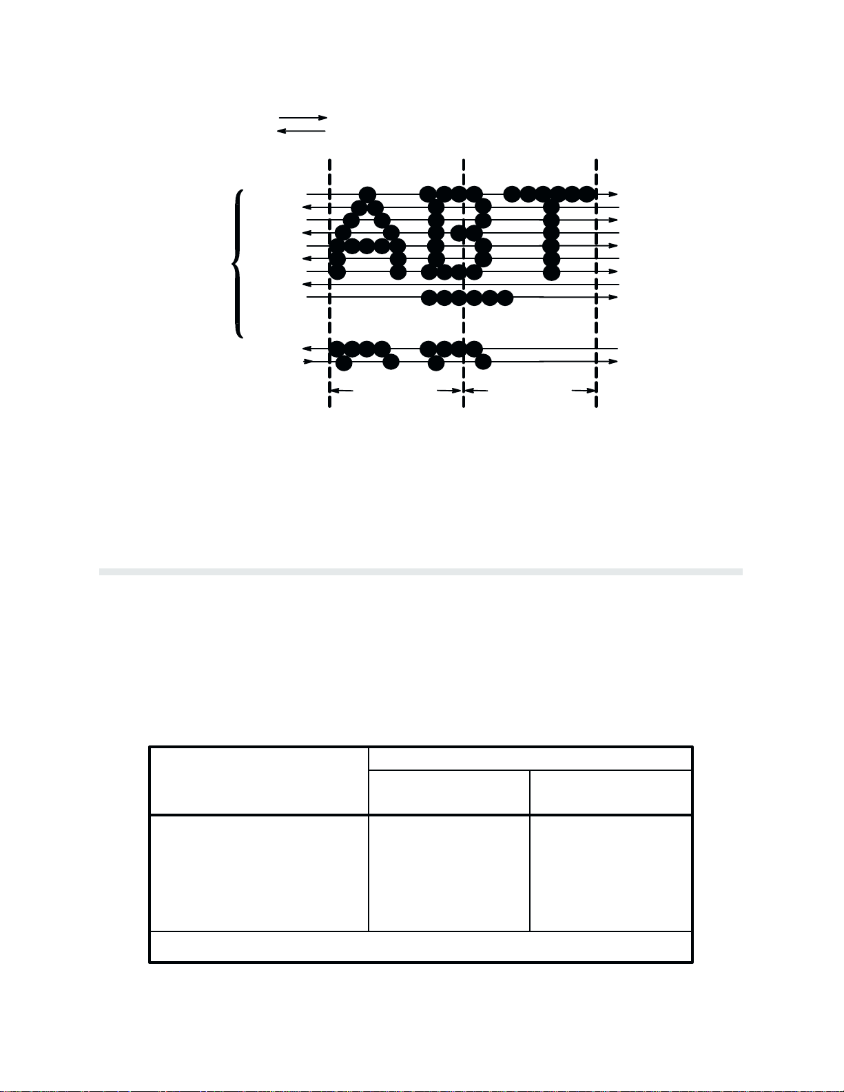
Character Formation
The
P9012 printer generates characters by assembling groups of dots in matrices. Dots
to produce a solid appearing character (Figure 1-1). Dot impressions are made by an assemĆ
bly
of 88 hammers installed on an oscillating shuttle. The hammers impact the paper through a
moving ink ribbon. Horizontal shuttle movement and vertical
precise
dot printing to form the character.
paper
advancement combine for
overlap
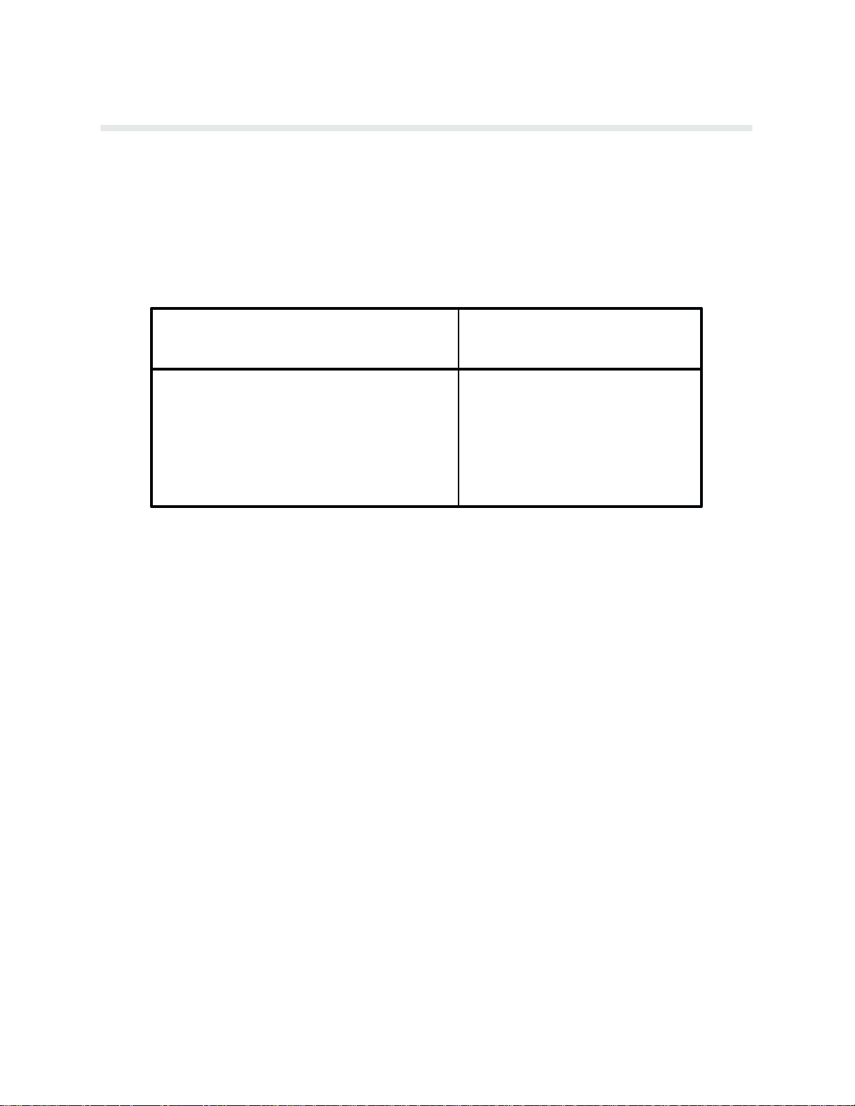
Line Matrix Printing
Unlike moving-head serial dot matrix printers, the Printronix P9012 printer creates graphics
and
characters by printing an entire dot row at one time. Dots are printed in both directions of
shuttle travel at a printer stroke length of .15" to print through 1.5 character positions in 10
pitch
Data P
achieve higher print duty cycles than moving head dot matrix (serial) printers.
During each sweep of the shuttle, hammers are activated to print dots at selected positions in
that
dot row. When the shuttle reaches the end of a sweep, it reverses direction, paper advances
one
dot row, and the hammers print the next consecutive row of dots.
After an entire line of characters is printed, hammer print action ceases and the paper adĆ
vances
of
characters. The number of rows allowed for line separation depends on the line spacing se
lected.
rocessing print mode (Figure 1-2). By printing a row of dots, line matrix printers
to the
first dot row of the next print line. This creates a series of blank rows between lines
Figure 1-1. T
ypical Character F
ormation
Ć
1-3Overview
Page 16
DIRECTION OF SHUTTLE MOVEMENT
CHARACTER
NOTE: P9012 SHUTTLE SWEEPS THROUGH 1.5 CHARACTER POSITIONS AT 10 CPI
Print Rate
ONE
ROW
DOT
ROW START
1
2
3
4
5
6
7
8
*
9
**
10
11
SPACE
12
1
2
1 HAMMER
PRINT SPAN
USED FOR LOWERCASE DESCENDER ONLY
*
USED FOR UNDERLINE AND LOWERCASE DESCENDER
**
Figure 1-2. Line Matrix P
1 HAMMER
PRINT SPAN
rinting
PAPER
ADVANCES
PAPER
FEED
PAPER
ADVANCES
The print rate, in lines per minute (lpm), is a function of the number of dot rows required to
produce the character line regardless of the number of characters in the line. For example,
more
dot rows are required to print lowercase characters with descenders; consequently, those
characters
are printed at a slower rate. T
able 1-1 describes the print
rate according to type of
character printed and print mode. Complete printing specifications are provided in the ApĆ
pendix.
Table 1-1.
P
rint Rate
P9012 PRINT RATE (LPM)
Uppercase Characters Upper & Lowercase
Print Mode
High Speed A (HS)
High Speed B (HSB)
High Speed C (HSC)
Data Processing (DP)
Correspondence (NLQ)
(No Descenders) Characters
1200
1030*
1030*
900
480
1030
900
800
720
370
*1030 lpm at 8 lpi; at 6 lpi, the print rate is slightly lower.
Overview1-4
Page 17
Plot Rate
As
well as character printing, the P9012 printer is capable of dot-addressable graphic plotting.
Based
ics
is used; the plot rate specifications apply to both P-Series and Serial Matrix types of graph
ic
plotting. The plot rate (in inches per minute, ipm," bidirectional) is described in T
according to the dot density (in dots per inch, dpi). Complete plotting specifications are proĆ
vided
on the protocol selected, either P-Series Plot Mode or Serial Matrix Bit Image Graph
able 1-2
in the Appendix.
T
able 1-2. Plot Rate
P9012 Plot RateDensity (dpi)
(ipm)
60 Horiz x 48 Vert (HS mode) 150
60 Horiz x 72 Vert (HSB mode)
100
Ć
Ć
60 Horiz x 72 Vert (HSC mode)
60 Horiz x 72 Vert (DP mode)
90 Horiz x 96 Vert (NLQ mode)
NOTE: Unidirectional plotting produces better print quality than bi-directional, and
be selected from the control panel; however
can
to half.
, unidirectional plot reduces the plot rate
100
100
50
1-5Overview
Page 18

Overview1-6
Page 19

Operation Features
On Line
The
P9012 printer functions either on line" or off line."
of receiving data and control commands from the host computer. The message display on the
printer
control panel indicates that the printer is on line and shows the current print mode.
Off Line
When
the printer is off line, communication
porarily stopped and the message OFFLINE READY appears on the display. Set the printer
off
line to perform the following tasks which are described in this chapter:
CHAPTER 2
OPERATION
When on line, the printer is capable
between the printer and the host computer is tem
Ć
n
Display/Change Configuration
Values
n Run the Self-Test n L
n Set/A
n
n
dvance T
Enter Hex Dump Mode
Set Line Spacing
op-of-Form n
n A
n
djust P
Set F
orms L
oad P
aper and Ribbon
Change P
aper T
ength
rint Modes
ractors
Command Sets (Protocol Modes)
The P9012 printer responds to two different command sets, or protocols: P-Series and Serial
Matrix.
The protocol is selected from the control panel and must correspond with the host programĆ
ming standard to communicate with the printer. P-Series protocol generates characters and
graphics using Printronix standard P-Series control codes. The Serial Matrix protocol generĆ
ates characters and graphics using Serial Matrix control codes similar to the IBM Graphics
Printer.
tocols.
R
efer to the P
rogramming chapter for
information on P-Series and Serial Matrix pro
Character Set Options
Ć
Four
basic character set choices are selectable from the control panel:
DEC Multinational, and ECMA 94 Latin 1. Within each character set, foreign language sets
are
also selectable. A
dditionally, OCR-A and OCR-B character sets are available.
IBM PC, Multinational,
2-1Operation
Page 20

Yo u
can
also define and download an international language to allow any character within the
character library to be substituted for any code. Similarly, an individual character in a font, or
an
entire set of characters, can be created
discussed
Power Switch
in more detail in the P
and placed in a font. These downloading features are
rogramming chapter and the Appendix.
The AC power switch is located at the lower left corner of the rear panel of the printer. T
the
printer power on, set the power switch to the ON (|) position.
The
power cord requires an IEC (hot) connector to mate to the receptacle on the rear
panel
of the printer
use
of cordsets that are not of the correct rating for the printer
Das Stromkabel benötigt einen IEC (spannungsführenden) Stecker, der in die
Steckdose an der hinteren Wand des Druckers passt. Der spannungsführende
Stecker kommt mit einem Nulleiter, der die Benutzung von Stromkabeln ohne die
korrekte
Nennleistung für den Dr
The Control Panel
The
printer control panel
discussed on the following pages.
Status Lamps
o turn
- WARNING -
. The hot connector includes a polarizing key which prevents the
.
- WARNUNG -
ucker verhindert.
is illustrated in Figure 2-1. Each component of the control panel is
The
status lamps are lit continuously when the printer is on line to the host and are off when the
printer
is off line. The lamps flash alternately if a fault condition exists in the printer.
Alphanumeric Message Display
The
message display shows printer status and fault
tion,
the display indicates the on line status and the current print mode (and pitch) selection.
condition messages. During normal opera
Ć
Operation2-2
Page 21
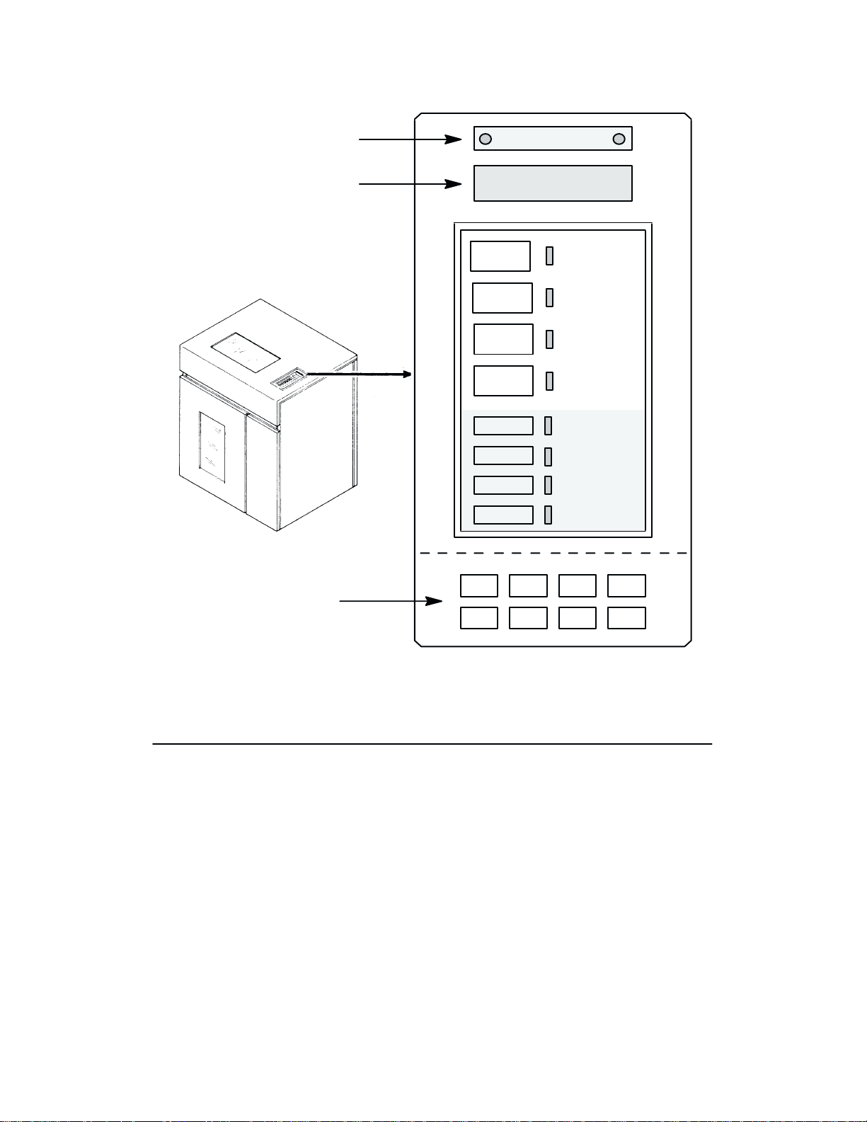
STATUS LAMPS
ALPHANUMERIC
MESSAGE DISPLAY
NOTE: THESE SWITCHES
ARE VISIBLE ONLY WITH
THE PRINTER COVER OPEN
MENU
UP
MENU
DOWN
ON LINE
CLEAR
6/8
LPI
PAPER
ADV
HOLD
ENABLE
REPRINT
PA1
CANCEL
PA2
ALT
MODE
NEXT
PREV
ON LINE
CHECK
8 LPI
VFU
LOADED
PROVIDED
WITH
PI-3287
OPTION
RUN/
STOP
ENTER
PRINT
MODE
F/L
Figure 2-1. Control P
anel
ON LINE Switch
Press
this switch to place the printer alternately on line or off
the
ON LINE light-emitting diode (LED) next to the
switch will be lit. The printer must be on
line to receive data from the host computer. When the printer is on line, the display will indiĆ
cate the current print mode, and only the PAPER ADV switch on the control panel will funcĆ
tion. When the printer is off line, the display will indicate OFFLINE READY, the ON LINE
LED
will flash alternately, all switches are active (except the ENTER switch unless it has been
unlocked), and the printer cannot communicate with the host computer. The printer must be
off line to change printing format or configuration and will go off line automatically if a fault
occurs.
If the display shows OFFLINE HEX DUMP (a diagnostic selection), pressing the ON LINE
switch
will cause the printer to go on line and data from the host computer will then be printed
in hex dump" format. The display shows ON LINE HEX DUMP. Pressing the ON LINE
switch
again will take the printer back to the OFFLINE HEX DUMP state.
line. When the printer is on line,
2-3Operation
Page 22

CLEAR Switch and CHECK Indicator
If a fault condition occurs, a fault message appears on the Message Display, and the CHECK
indicator
to
will be validated and the display updated. If all faults were corrected, the display will indicate
the
In
reset
1. CLEAR and RUN/STOP, pressed simultaneously, reset the printer. The printer may be
flashes alternately with the
the printer that a fault condition has been corrected. After pressing CLEAR, the fault status
printer is off line.
addition, the CLEAR switch also has the special functions noted below. Except when used to
the printer (#1 below), the CLEAR switch operates only when the printer is off line.
at any time, on line,
reset
printer
be reset only when off line and no data is in the buffer, or loss of data may result.
ON LINE indicator. P
off line, or while printing. However, it is recommended that the
ress the CLEAR switch to indicate
2. CLEAR
of-Form on page 2-9).
3. Pressing CLEAR when a configuration parameter value is displayed returns the printer
to
chapter.
4. Pressing
is used with the P
off line status. R
CLEAR will silence the audio alarm during a fault condition.
efer to the Control P
APER AD
V switch to set top-of-form (refer to Setting T
anel
Configuration Diagram in the Configuration
op-
6/8 LPI Switch
Press
this switch to display the current line spacing in lines per inch (lpi). Subsequently pressing
this
switch steps the selection through 6, 8 and 10.3 (7/72") lpi.
required
than
to select the line spacing. The LED next to this switch lights when line spacing is
6 lpi. The 6/8 LPI switch functions only when the printer is off line.
NOTE: Line spacing control from the host computer will override the switch setting.
Control codes from the host computer can select a line spacing other than the 6, 8, or
10.3
lpi, and that selection will be reflected on the message display
Use of the ENTER switch is not
other
.
PAPER ADV Switch
With the printer on line, momentarily press PAPER ADV to advance the paper one line; or,
press and hold PAPER ADV to advance to the next top-of-form.
ured
to advance the paper only after printing any data remaining in the buffer, or to move pa
per
without printing (refer to the Configuration chapter). The P
to
set top-of-form (refer to Setting T
functions
to
advance to the next top-of-form. If there is any data in the buffer, this action will not oc
cur, and the message ON LINE DATA IN BUFFER will be momentarily displayed.
when the printer is on line. When the printer is on line, press the P
op-of-Form on page 2-9). The PAPER AD
This switch can be config
APER AD
V switch is also
APER AD
used
V switch
V switch
Ć
Ć
Ć
VFU LOADED Indicator
This
LED indicator lights when the form (paper) format is being controlled by the V
mat Unit (refer to the Configuration and VFU chapters). When the appropriate VFU is seĆ
lected
by the operator and loaded by the host computer, this indicator will illuminate.
ertical F
orĆ
Operation2-4
Page 23

HOLD ENABLE, REPRINT PA1, CANCEL PA2, ALT MODE
(Optional Switches)
These four switches and their associated LEDs are included on printers equipped with a
Printronix PI-3287 printer interface and operate independently of all other control panel
switches.
may then be used with an IBM 3274 or 3276 control unit. Information on the operation and
function
is
not configured to emulate an IBM 3287 printer, these switches are not provided.
The PI-3287 enables a
of these switches is contained
Printronix
printer to emulate an IBM 3287 printer; the printer
in the PI-3287 User's R
eference Manual. If the printer
THE SWITCHES DESCRIBED BELOW ARE ACCES
AISING THE PRINTER CO
R
VER:
SED B
Y
MENU UP, MENU DOWN, NEXT, and PREV Switches
Pressing MENU UP and MENU DOWN simultaneously (from the OFFLINE READY disĆ
play)
will alternately lock and
action. The MENU UP, MENU DOWN, NEXT, and PREV switches are also used to display
configuration parameter main menus, submenus, and certain diagnostic tests. After the reĆ
quired menu is displayed, individual parameters are displayed using the NEXT and PREV
switches as shown on the Control Panel Configuration Diagram in
The value shown on the display with an asterisk (*) is the currently active parameter value reĆ
tained in printer memory.
NOTE: When the printer is off line, configuration menus and parameter values may be
viewed
at any time, but
The ENTER switch loads a displayed value into printer working memory. The ENTER
may only be unlocked when the printer is off line; it cannot be unlocked or locked
switch
from
within a menu.
unlock the ENTER switch. No other switches are affected by this
the Configuration chapter.
may only be changed by unlocking and using the ENTER switch.
RUN/STOP
RUN/STOP performs the following functions:
n P
ress RUN/STOP simultaneously with CLEAR to reset the printer.
n If a diagnostic test is selected and shown on the display, press RUN/STOP to start
the
test and press it again to stop the test.
n If the CONFIGURATION PRINTOUT message is selected and shown on the disĆ
press RUN/STOP to print a list of the current configuration.
play,
ENTER
Press ENTER to enter a displayed parameter value into printer working memory. The previĆ
ous
value is replaced by the displayed value. The ENTER switch must be used to alter a menu
selection and those parameters displayed using the PRINT MODE and F/L switches. FuncĆ
tions
activated by the RUN/STOP and 6/8 LPI switches do not use the ENTER switch.
2-5Operation
Page 24

The ENTER switch must be enabled (unlocked) before making configuration or format
changes. Simultaneously pressing MENU UP and MENU DOWN alternately locks and unĆ
locks the ENTER switch. (This sequence protects against accidental reconfiguration.) ResetĆ
ting
the printer
are affected by this action. This action can only be done when the display shows OFFLINE,
after which the display will read either ENTER SWITCH NOT LOCKED or ENTER
SWITCH
or turning the power off and on will lock the ENTER switch. No other switches
LOCKED for approximately one second. The display then returns to OFFLINE.
PRINT MODE
The PRINT MODE switch functions only with the printer off line. P
the current print mode. Subsequently pressing the NEXT, PREV, or PRINT MODE switches
updates
is
the Message Display through all of the available print modes listed below. P
selected with the ENTER switch.
High Speed A (HS) at 10, 12, 13.3, 15, and 17.1 cpi
High Speed B (HSB) at 10, 12, 13.3, 15, and 17.1 cpi
High Speed C (HSC) at 10, 12, 13.3, 15, and 17.1 cpi
Data P
rocessing (DP) at 10, 12, 13.3, 15, and 17.1 cpi
Correspondence (NLQ) at 10, 12, and 15 cpi
OCR-A at 10 cpi
OCR-B at 10 cpi
NOTE: Print mode control from the host computer will override the control panel setĆ
ting.
ress this
switch to display
rint
mode
F/L (Forms Length)
The F/L switch functions only with the printer off line. Press F/L to enter the Forms Length
menus.
F
orms length is selected with the ENTER switch.
Forms Length can be selected in inches or lines via printer configuration. Refer to Setting
Forms L
ength on page 2-16.
Forms Length can also be set by control code from the host computer. Forms length control
from the host computer will override the control panel setting. Refer to the Programming
chapter
for details.
Operation2-6
Page 25

Loading Paper
The
P9012 printer uses standard fanfold paper from 3 to 16 inches wide and 15 to 100 lb bond
(0.025 inches thick maximum). To load paper, perform the following steps and refer to
Figure 2-2.
1. Place
2. Fully
3. Open
4. Open the front printer door and align the paper supply with the position of the tractors.
5. Load
6. Press PAPER ADV to advance paper into the paper stacking area. Verify unobstructed
the printer off line and raise the printer cover.
raise the F
the status lamps will flash alternately, and the display will indicate a platen open condiĆ
tion).
both tractor gates (B) by swinging them out.
Feed
the paper up through the paper slot (C). Push the paper up until it
ribbon
mask (D). If the paper snags, fold the top edge down before feeding.
the paper on the tractor sprockets (E); close the tractor gates (B). Unlock the right
tractor
lock (F) by raising or
paper slack or to adjust for various paper widths. After positioning the tractor, lock it in
place.
NOTE: Lock the left tractor in alignment with the number 1" on the paper scale to set
the
left margin with the first character position. Once properly positioned, further adjust
are not required unless a change is made to the left print margin.
ments
paper
feeding.
orms Thickness A
lowering it to the center position; slide the tractor to remove
djustment L
ever (A). (The CHECK indicator will light,
appears above the
Ć
7. If necessary, use the Horizontal Adjustment Knob (G) to make fine adjustments to the
left
margin. The paper can be shifted left or right up to approximately
8. Set
9. Set the Forms Thickness Adjustment Lever (A) with slight friction to approximate the
10.
11. Perform
12. Press
the top-of-form as described in Setting T
paper
thickness. The A-B-C scale indicates relative positioning to correspond approxi
mately
with 1-to 6-part paper thicknesses.
NOTE: If the Forms Thickness Adjustment Lever is set incorrectly, the print will show
wavy
vertical lines (known as poor phasing or light print). If set too tightly
tion may cause the shuttle to smear or tear the paper, damage labels, or cause errors in
form
positioning.
Close the printer cover and door.
the P
aper Stacking instructions (page 2-11) to start the paper stacking properly.
CLEAR to update the display and place the printer on line.
op-of-F
orm (page 2-9).
!/4 inch.
, excessive fric
Ć
Ć
2-7Operation
Page 26
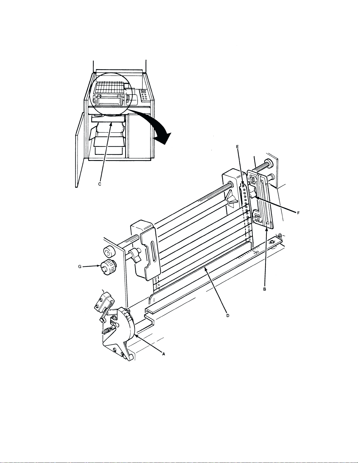
Figure 2-2. Loading P
aper
Operation2-8
Page 27

Setting Top-Of-Form
Top-of-form determines where the first line of print will appear and is set when paper is
loaded.
foration
Once top-of-form has been set, the paper can be advanced to the top of the next form by
pressing the PAPER ADV switch. Unless otherwise configured, the P9012 printer assumes
11-inch length paper is used. For alternate length forms, refer to Setting Forms Length on
page 2-16.
There are two methods of setting top-of-form. The first method uses forward paper motion
and
reverse
The
is different from the actual form length set (for example, when the host sets the forms length
for non-standard length forms). The reverse paper motion method of setting top-of-form
reverse feeds the paper backward a fixed number of inches and does not use the forms length
currently
T
ypically, the first line of print is set approximately one-half inch below
unless specific application requirements dictate otherwise.
is performed with the F
paper motion and is performed with the F
reverse paper motion method should be used when the forms length setting in the printer
set in the printer.
NOTE: Do not use the reverse paper motion method of setting top-of-form for heavy
forms
or peel-off label forms.
orms Thickness A
djustment L
orms Thickness A
the paper per
ever closed. The second method uses
djustment L
ever open.
Ć
Setting Top-of-Form - Forward Paper Motion
1. Place
2. Move the Forms Thickness Adjustment Lever to the fully open position. (The CHECK
3. Rotate the Vertical Position Knob to align the first line to be printed with the top-of-
4. Close the Forms Thickness Adjustment Lever to the appropriate paper thickness posiĆ
5. Press and release the CLEAR and PAPER ADV switches simultaneously. The paper will
6.
the printer off line and raise the printer cover.
indicator will light, the status lamps will flash alternately, and FAULT CONDITION
PLATEN
form
tion.
advance
TOP OF FORM SET.
Close the printer cover and place the printer on line.
OPEN will be displayed.)
alignment indicator on the left tractor gate (Figure 2-3).
to the
top of form position on the next form. The display will indicate OFFLINE/
2-9Operation
Page 28
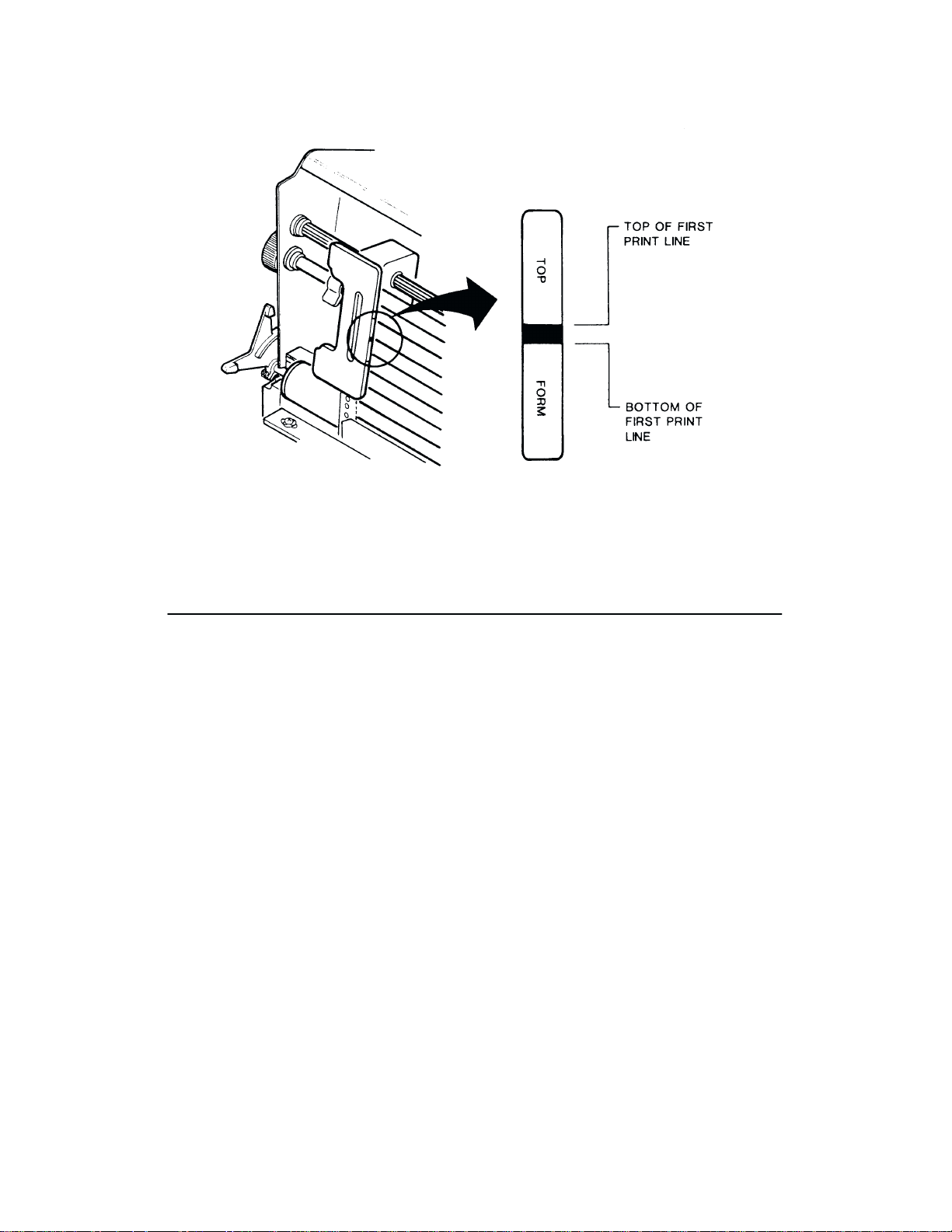
Figure 2-3. Setting Top-of-Form
Setting Top-of-Form - Reverse Paper Motion
NOTE:
bel forms.
Place the printer off line and raise the printer cover.
1.
2. Move the Forms Thickness Adjustment Lever to the fully open position. (The CHECK
indicator will light, the status lamps will flash alternately, and FAULT CONDITION
PLATEN
3. Rotate the Vertical Position Knob to align the first line to be printed with the top-ofform
NOTE: Be sure there is enough paper extending through the tractor area so that forms
will
4. Press and release the CLEAR and PAPER ADV switches simultaneously. The paper will
reverse feed to the top of form position on the
5. Close the Forms Thickness Adjustment Lever to the appropriate paper thickness posiĆ
tion.
6. Press
7.
Close printer cover and place the printer on line.
Do not use this method of setting top-of-form for heavy forms or peel-off
OPEN will be displayed.)
alignment indicator on the left tractor gate (Figure 2-3).
not run out of the tractors during the reverse feed in the following step.
current
form.
the CLEAR switch to clear the PLA
TEN OPEN fault condition.
la
Ć
Operation2-10
Page 29

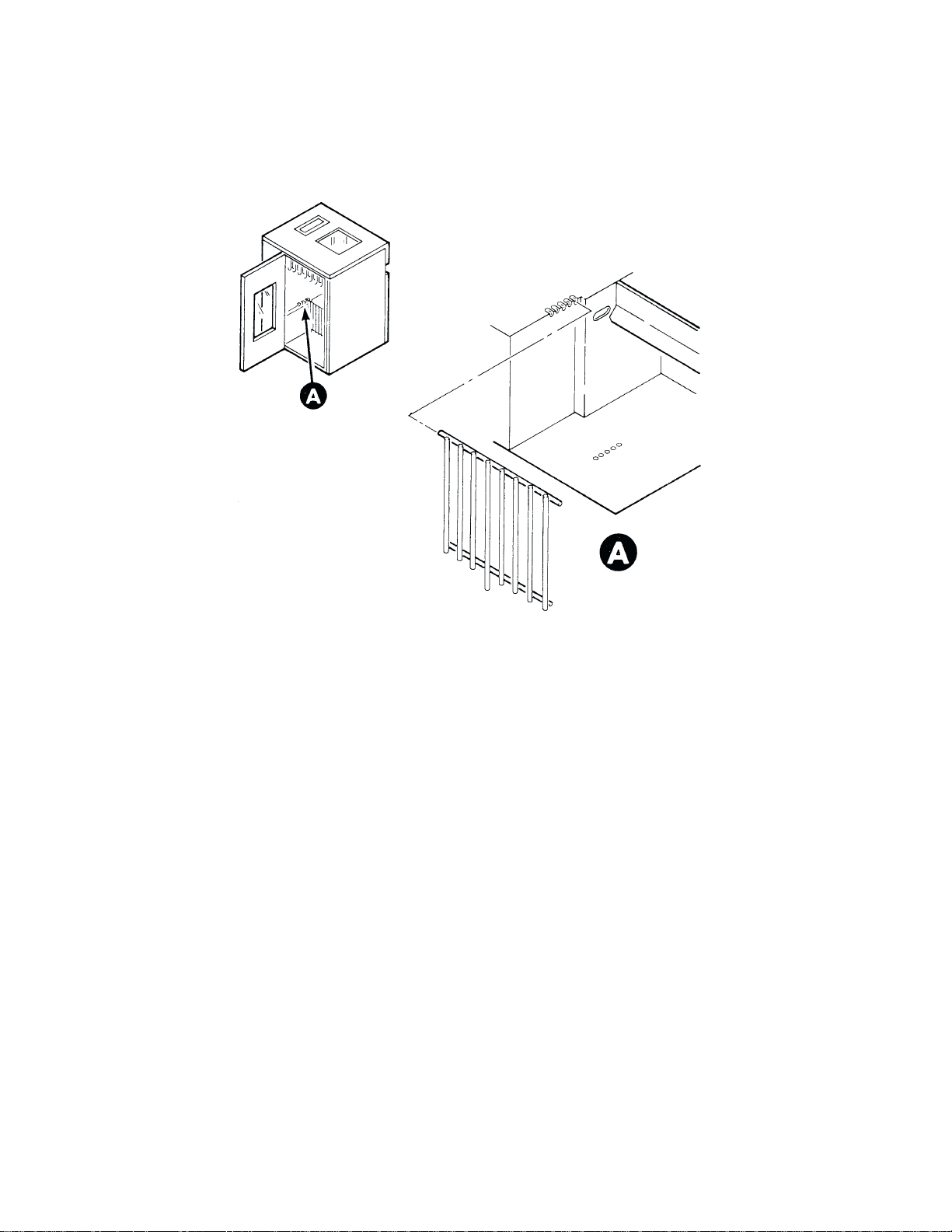
Paper Stacking
The
printer can stack at least half a box of standard computer paper when the paper is properly
loaded.
1.
After loading the paper, perform the following steps.
Open the rear cabinet door to access the paper stacking area.
NOTE: Step 2 pertains to installation of the front paper stacking fence. (The rear fence
on the rear cabinet door is installed at the factory.) If the front fence has already been
installed,
continue with the paper stacking instructions at step 3.
2. Install
3. Install the paper stacking tent into the paper stacking area with the far edge of the tent
4. Center the outer edges of the tent with the outer edges of the paper supply as seen
5. A
6. V
7. R
8. Repeat step 6. Any adjustments to the paper stack can be made while the printer is runĆ
the front paper fence in the bracket as close as possible to the paper in the stacking
area
with the paper close to the rear door (Figure 2-4). The bracket is located in the up
per portion of the printer paper stacking area near the outer edges. The fence must be
installed
against
through
a.
b.
c. The paper is following a straight path down to the tent in alignment with the outer
d. The
ning. If an adjustment is made, again check the stack after approximately 15 to 20 sheets
have
in the same bracket position on each side to maintain a vertical orientation.
the front paper fence (Figure 2-5).
the printer cabinet.
dvance the paper until a few sheets begin to stack on the tent (Figure 2-6).
erify the following and make any necessary adjustments.
The paper stack is centered on the tent
The paper perforation folds are folding naturally.
edges.
paper is against the front paper fence as it rests centered on the tent.
un the printer and stack approximately 15 to 20 sheets of paper.
been processed.
.
Ć
NOTE: If the paper is not stacking properly, check the following items in addition to
listed in step 6.
those
NOTE 1: If printing occurs across the paper perforations, the paper may not stack corĆ
rectly. Adjust the Skip-Over Perforation configuration parameter to eliminate printing
across the paper perforations.
NOTE 2: If the paper path is too close to either side panel, paper stacking can be disĆ
rupted.
Adjust the paper path toward the
NOTE
3: The front paper fence may be incorrectly positioned. R
fence into one of the other bracket locations.
center of the printer
, away from the side panels.
eposition the front paper
2-11Operation
Page 30
NOTE
4: Check that the chains are properly installed (see Installation chapter) and that
they
engage the paper
.
Figure 2-4. F
ront P
aper F
ence Installation
Operation2-12
Page 31
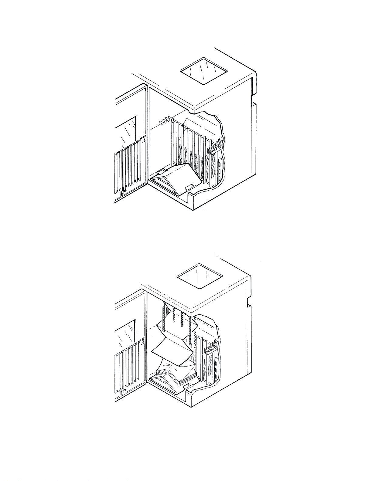
Figure 2-5. P
aper T
ent Installation
Figure 2-6. P
aper Stacking
2-13Operation
Page 32

Unloading Paper
1. Place
2. T
3. F
4.
5. Gently
the printer off line and raise the printer cover.
ear off the paper below the paper slot.
ully raise the F
Open both tractor gates and remove the paper from the tractor sprockets.
pull the paper up through the paper
sprocket
holes catch on the ribbon mask.
orms Thickness A
Replacing The Ribbon
Each
printer is shipped with a standard black ink, one-inch nylon fabric ribbon on two spools.
OCR
(extra dark) ribbons are also available. R
light
or after each box of standard size computer paper. Use only ribbons that meet the specifi
cations
stated in Specifications, Appendix C.
NOTE: T
o replace the ribbon, perform the following steps and refer to Figure 2-7.
T
1.
Place the printer off line and raise the printer cover.
o use RibbonMinder features, refer to the RibbonMinder chapter
djustment L
slot. Be careful not to let paper perforations or
eplace the ribbon when
ever.
the print contrast is too
Ć
.
2. F
ully raise the F
3. Unlatch
of
4. Place
spool
5. P
6. Thread the ribbon around the two ribbon guides (E) and through the ribbon path as
shown
thin
turn the ribbon spools to ensure that the ribbon is tracking correctly in the ribbon path,
and
The ribbon must not be twisted. A twisted ribbon can lower print quality, shorten
ribbon
Der Farbband darf nicht verdreht sein. Ein verdrehter Farbband kann die DruckĆ
qualität und die Farbbandlebensdaür erniedrigen, oder könnte
Papiertransportfehler
the ribbon spools (B) and carefully lift them off the hubs (C). R
the ribbon path. Discard the used ribbon.
each new ribbon spool (B) on a hub (C) with the ribbon to the outside. Either ribbon
can be loaded on either hub.
ress the spools down until the latch (D) snaps in place.
in the diagram (F) on the ribbon deck cover. The ribbon must pass between the two
metallic strips called the hammer bank cover (G) and the ribbon mask (H). Manually
the reversal strip is between the hub and the ribbon guide.
life, or cause paper jams.
orms Thickness A
- CAUTION -
- VORSICHT -
hervorr
ufen.
djustment L
ever (A) to open the platen.
aise the ribbon out
Operation2-14
Page 33

7. Lower
the F
orms Thickness A
Figure 2-7. Ribbon Replacement
djustment L
ever (A) to the appropriate operating
position.
8. Press
9.
CLEAR (on the control panel) to clear the PLA
Close the printer cover and place the printer on line.
TEN OPEN fault condition.
2-15Operation
Page 34

Setting Forms Length
NOTE: Forms length can also be set by control code from the host
override the control panel setting. Using control codes, the host computer can specify
forms lengths other than those available from the control panel. Refer to the ProgramĆ
ming chapter for more information.
printer uses continuous, tractor-fed paper with the forms length set between 1.0 and 24.0
The
inches,
or between 1 and 192
8
lpi does not change the line spacing.
The
printer has been preset for 11-inch length paper. When using paper of a different length,
the top-of-form setting and the forms length setting must be changed to match the desigĆ
nated
length. T
1.
Place the printer off line and raise the printer cover.
2. Simultaneously press MENU UP and MENU DOWN to unlock the printer configuraĆ
tion.
3. P
ress F/L; the display will show FORMS LENG
4. Press
6
LPI LINES, FORMS LENG
INCHES.
o set the forms length:
ENTER SWITCH NOT LOCKED will be displayed briefly.
NEXT or PREV to cycle through the following options: FORMS
Select an option, and perform the corresponding instructions below.
lines
at 6 or 8 lines per inch. Setting the forms length in lines at 6 or
TH SET IN INCHES.
TH SET IN 8 LPI LINES, and FORMS LENG
computer which will
LENG
TH SET IN
TH SET IN
To Set Forms Length in Inches
1. Press NEXT or PREV until FORMS LENG
2. P
ress MENU DOWN or F/L to display the current forms length in inches.
3. P
ress NEXT or F/L to increase the forms length in 0.5-inch increments, or press PREV
to decrease the forms length in 0.5-inch increments. When the appropriate value is disĆ
played,
4. P
5. P
Simultaneously press MENU UP and MENU DOWN to lock the printer configuration.
6.
7.
Set the top of form according the the instructions on page 2-9.
8.
Close printer cover and place the printer on line.
save it as described below.
ress ENTER to select the displayed forms length.
ress CLEAR to return to OFFLINE READ
TH SET IN INCHES is displayed.
Y.
To Set Forms Length in Lines
1. Press NEXT or PREV until FORMS LENGTH SET IN 6 LPI LINES or FORMS
LENGTH
SET IN 8 LPI LINES is displayed.
Operation2-16
Page 35

2. P
ress MENU DOWN to display the current forms length in lines.
3. Press
4. P
5. P
6.
7.
8.
NEXT or PREV to increase or decrease the forms length in 1-line increments, re
spectively.
ress ENTER to select the displayed forms length.
ress CLEAR to return to OFFLINE READ
Simultaneously press MENU UP and MENU DOWN to lock the printer configuration.
Set the top of form according the the instructions on page 2-9.
Close printer cover and place the printer on line.
When the appropriate value is displayed, save it as described below.
Selecting Print Mode
During normal operation, the message display indicates the printer is on line and what print
is currently selected; for example:
mode
ON LINE
DP A
T 10 CPI
1.
Place the printer off line and raise the printer cover.
2. Simultaneously press MENU UP and MENU DOWN. ENTER SWITCH NOT
LOCKED
will be displayed briefly.
Ć
Y.
3. P
ress PRINT MODE; the currently selected print mode will be displayed.
4. Press NEXT, PREV, or PRINT MODE to cycle through the various print mode options.
The
following print mode options are available:
Data P
rocessing (DP) at 10, 12, 13.3, 15, and 17.1 cpi
Correspondence (NLQ) at 10, 12 and 15 cpi
High Speed A (HS) at 10, 12, 13.3, 15, and 17.1 cpi
High Speed B (HSB) at 10, 12, 13.3, 15 and 17.1 cpi
High Speed C (HSC) at 10, 12, 13.3, 15 and 17.1 cpi
OCR-A and OCR-B at 10 cpi
NOTE:
ly,
5.
When the desired print mode is shown on the display, press the ENTER switch.
6. Press CLEAR to return the printer to off line status. The display will read OFFLINE
READY.
7. Simultaneously
8.
Close printer cover and place the printer on line.
The control panel actually displays 13 or 17 cpi when 13.3 or 17.1 cpi, respective
is selected.
press MENU UP and MENU DOWN to lock the printer configuration.
Ć
2-17Operation
Page 36

For additional printing capabilities and character attributes, refer to the Programming chapĆ
ter.
P
rint mode control from the host will override the control panel setting.
Setting Line Spacing
P9012
printers can be set for a line spacing of 6, 8, or 10.3 lines per inch (lpi) from the control
panel
by using the 6/8 LPI switch. T
following
1.
2. P
procedure.
Place the printer off line.
ress 6/8 LPI; the currently selected lpi setting will be displayed.
o select the line spacing from the control panel, perform the
3. Press
4. P
5.
Line
as described in the Programming chapter. Using control codes, the host computer can specify
line
ride
NEXT
The
light beside
ress CLEAR when the desired line spacing setting is displayed; the printer will be placed
off
line and the display will read OFFLINE READ
Place the printer on line.
spacing can also be selected by sending line spacing control codes from the host computer
spacing other than 6, 8, or 10.3 lpi. Line spacing control from the host
the control panel setting.
Printer Reset
This
procedure resets the printer to the configuration values
ues), and the current form position becomes the top-of-form. The printer can be reset to the
power-up configuration values at any time: on line, off line, or while printing. However, it is
recommended
T
o reset the printer, press CLEAR and RUN/STOP simultaneously.
that the printer be reset only when off line to prevent the possible loss of data.
Hex Code Printout
, PREV
, or 6/8 LPI to step through the 6, 8, and 10.3 lines per inch selections.
the 6/8 LPI switch lights when the selected line spacing is other than 6 lpi.
Y.
computer will over
last saved
(not factory default
val
Ć
Ć
The hex code printout (often called a hex dump") are useful for debugging when
troubleshooting printer data reception problems. Hex dumps list ASCII character data reĆ
ceived
from the host with
print
their assigned symbol; nonprintable characters are indicated with a period
before
the hex code indicates an active P
code
indicates an inactive PI line. T
hex
code with A
1.
Place the printer off line and raise the printer cover.
2. Press MENU DOWN; repeatedly press NEXT or PREV until DIAGNOSTICS is disĆ
played.
SCII character equivalents, perform the following steps.
the corresponding two-digit hexadecimal code. P
aper Instruction (PI) line; a blank space before the hex
o print the data stream received from the
rintable characters
symbol. A p"
host computer in
Operation2-18
Page 37

3. Press MENU DOWN, then repeatedly press NEXT or PREV until the PRINT DATA
STREAM
4. P
ress MENU DOWN; the display will show OFFLINE HEX DUMP
IN HEX CODE message is displayed.
.
5. Press
6. Send
7. Press ON LINE again to stop the hex dump. The display will read OFFLINE HEX
8. Press
9.
ON LINE.
the data from the host; the hex dump will print.
DUMP.
CLEAR to return printer to OFFLINE READ
Close the printer cover and place the printer on line.
NOTE: Any data remaining in the buffer will be printed before the hex code printout
starts.
The display will indicate that the printer is on line and in hex dump mode.
Running the Self-Test
P9012
printers include various self-test functions. Use the self-test as needed to determine if
the
printer is functioning normally.
T
o run the self-tests:
1.
Place the printer off line and raise the printer cover.
Y.
2. Press MENU DOWN; repeatedly press NEXT or PREV until DIAGNOSTICS is disĆ
played.
3. Press MENU DOWN, then repeatedly press NEXT or PREV until either PRINTER
FULL WIDTH or PRINTER TEST 8 INCH WIDTH message is displayed.
TEST
4. To
5. P
Examine
rectly
6. P
7.
select one of the 8 INCH WIDTH or FULL WIDTH paper tests, press MENU DOWN
then repeatedly press NEXT or PREV until the appropriate test is displayed. Tests inĆ
clude
shift recycle, all Es, and others.
ress RUN/STOP to begin the selected self-test; press RUN/STOP again to stop it.
NOTE
: Any data remaining in the buffer will be printed before the self-test begins.
the print quality. The characters should be horizontally and vertically aligned and cor
formed. If print quality problems exist, contact your authorized service representative.
ress CLEAR to place the printer off line. The display will read OFFLINE READ
Close the printer cover and place the printer on line.
Y.
Ć
2-19Operation
Page 38

Fault Condition Messages
If a fault condition occurs in the printer, the CHECK light illuminates, the status lamps blink
alternately, and the first line of the message display reads FAULT CONDITION. If confiĆ
gured,
an alarm will
show the specific fault. (If the specific
CONDITION
D
Operator correctable faults
D
Field service required
NOTE: The alarm can be turned off before the fault is cleared by pressing the CLEAR
switch.
Operator Correctable Faults
Printer
problems that the operator can correct are self-explanatory and appear on the second
line
of the display:
P
APER OUT
PLATEN OPEN COVER OPEN
APER J
P
CHANGE RIBBON
sound when the F
will not be shown.) Displayed faults fall into one of two categories:
AM COOLING
ault Condition occurs. The second line of the display will
fault
description requires two lines, the message F
SHUTTLE STALL
AULT
After correcting an operator correctable fault, press the CLEAR switch before placing the
printer on line. If any other fault messages appear without an asterisk (*), press the CLEAR
to continue. However,
switch
tative
to correct the problem permanently.
if this problem persists, contact your authorized service represen
- IMPORTANT -
If NVM INITIALIZED PRESS CLEAR appears on the display every time the
printer power is cycled, non-volatile memory must be replaced. Non-volatile
memory can be temporarily
configuration data may be saved, and the factory default is loaded. Contact your
authorized
service representative to correct the fault permanently
bypassed by pressing the CLEAR switch. However, no
.
Ć
Operation2-20
Page 39

Field Service Required
Printer problems requiring the attention of an authorized service representative also appear
on
the second line of the display and are indicated by an asterisk (*) next to the message:
PROGRAM PROM *
NOVRAM *
FONT PROM *
HAMMER DR PCB X * ( X = 1, 2, or 3 )
If
HAMMER DR PCB X * appears on the display, printer power will automatically shut off 10
seconds
If, upon printer power-up, the lamps and/or LEDs flash and no message is provided in the
display,
after the fault message is displayed.
contact your authorized service representative to correct the fault permanently.
2-21Operation
Page 40

Operation2-22
Page 41

Introduction
CHAPTER 3
CONFIGURATION
Configuration
cates with the host computer. Most configuration parameters are selected from the control
panel, as shown in the Control Panel Configuration Diagram at the end of this chapter. Some
configuration
described in Appendix F. Such hardware configuration changes do not normally require
changes
Read this chapter before configuring any printer function. The following information is preĆ
sented:
n Lock/Unlock
n
n
n F
n
n Load Configuration Values
n
refers to the set of operating parameters that define how the printer communi
parameters are hardware selectable by
to the factory settings.
P
rinter Configuration
Configuration Menus
Configuration P
actory Default Configuration V
Configuration P
Control P
rintout
rocedure
anel Configuration Diagram
Lock/Unlock Printer Configuration
The ENTER switch must be unlocked to reconfigure the printer from the control panel. At
powerup,
change any configuration value, the ENTER switch must be unlocked. Pressing MENU UP
and MENU DOWN simultaneously (while the printer is off line) will alternately unlock and
lock the ENTER switch. The message display will briefly read ENTER SWITCH NOT
LOCKED or ENTER SWITCH LOCKED when the printer configuration is unlocked or
locked,
selected
the printer configuration is locked to prevent accidental reconfiguration.
respectively. While in the configuration menus, pressing the
value into printer configuration.
Ć
installing jumpers on the DCU board, as
alues
In order to
ENTER switch will enter a
Configuration Menus
With
the printer off line, pressing
displays the main configuration menus. The individual parameter values or secondary menus
displayed by again pressing MENU DOWN. All parameter options within a menu may be
are
viewed by pressing NEXT and PREV. Pressing MENU UP will step the configuration menu
back up one level.
MENU DOWN, then repeatedly pressing NEXT or PREV
3-1Configuration
Page 42

From
the main configuration menus below, related configuration parameter values can be dis
and selected.
played
D
Ribbon Life xxx%
D
Character Set
D
Application Compatibility
D P
aper F
ormat
D
Host Interface
D L
oad P
arameters
D Save Parameters
D Diagnostics
Ć
NOTE:
the
Once
the ENTER switch is unlocked, selected values can be saved as the current configuration
The xxx% in the Ribbon Life menu will not be displayed in the
RibbonMinder feature is disabled.
by displaying the value in the LCD and pressing ENTER. You can exit from a configuration
by pressing CLEAR which will place the printer off line.
menu
NOTE:
If an E" is displayed in the upper right corner of the LCD
an L" is displayed in the lower right corner of the LCD
Configuration Printout
The configuration printout lists all of the currently selected configuration parameter values.
Figure 3-1 is a sample configuration printout. Configuration parameters on the printout are
in the same order as the configuration menu via control panel.
listed
The following general procedure can be used to obtain a configuration printout. Refer to the
Control Panel Configuration Diagrams beginning on page 3-11 for an illustration of the butĆ
required to select and display the menus and values. When this mode is exited, the
tons
ous print mode and LPI is restored, and all print attributes are canceled. All other format
parameters are unaffected.
LCD message if
, the VFU is enabled. If
, the VFU is loaded.
previ
Ć
Place the printer off line and raise the printer cover.
1.
2. Select and display the CONFIGURATION PRINTOUT menu in the DIAGNOSTICS
menu by pressing MENU DOWN and then PREV until DIAGNOSTICS appears in the
message
display.
3. Press MENU DOWN to display CONFIGURATION PRINTOUT in the message disĆ
play.
4. Press
5. P
6.
RUN/STOP
ress CLEAR to return to OFFLINE READ
. The configuration printout will print.
Y.
Close the printer cover and place the printer on line.
Configuration3-2
Page 43
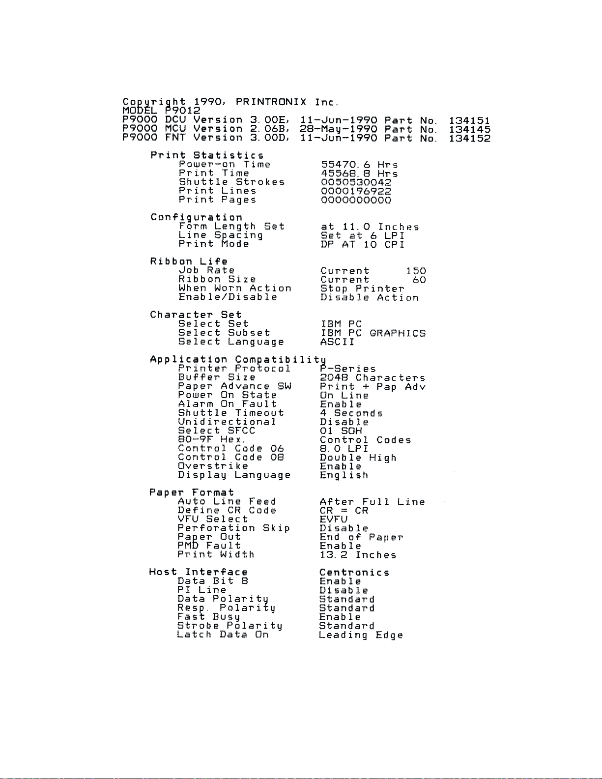
Figure 3-1. Sample Configuration P
rintout
3-3Configuration
Page 44

Factory Default Configuration Values
Printronix
tional
application, but factory default values remain accessible using the LOAD PARAMETERS
menu. On the Control Panel Configuration Diagrams, factory configuration values are indiĆ
cated
Configuration Factory Default
Parameter Value
Forms Length
Line Spacing
Print Mode
Select Set
Select Subset
Select Language
Ribbon Life
Ribbon Size
Job Rate
When Worn Action
Printer Action
Printer Protocol
Buffer Size
Printer Select Disable
Paper Advance Switch Print & Paper Advance
Power On State Online
Alarm On Fault Enable
Shuttle Timeout 4 Seconds
Unidirectional Disable
Select SFCC 01 SOH
80-9F Hex Control Codes
Control Code 08 Double High
Control Code 06
Overstrike
Display Language English
Auto Line Feed
Define CR Code CR = CR
VFU Select
factory default configuration values are shown in T
when the printer is received. New values can be saved and applied as necessary for each
by an asterisk (*). (The asterisk is not shown on the printer display.)
T
able 3-1. P
11.0 Inches
6 lpi
DP 10 cpi
IBM PC
IBM PC Graphics
ASCII
100
60
150
Stop Printer
Disable
P-Series
2048 Characters
8 LPI
Enable
After Full Line
EVFU
rintronix F
actory Default Configuration V
Configuration Factory Default
Perforation Skip
Paper Out
PMD Fault
Line Width 13.2 Inches
Host Interface Centronics
Parallel Interface:
Serial RS-232 Interface:
Data Protocol
Data Rate
Word Length
Stop Bits
Parity
Bit 8 Function
CD and DSR
CTS and DSR
Data Term Ready
Request to Send
Reverse Channel
able 3-1. These
Parameter Value
Data Bit 8
PI Line (Dataproducts) Enable
PI Line (Centronics) Disable
Data Polarity
Resp. Polarity Standard
Latch Data On
Fast Busy (Centronics)
Strobe Polarity
values are opera
alues
Ć
Disable
End of Paper
Enable
Enable
Standard
Leading Edge
Enable
Standard
X-On / X-Off
9600 Baud
8 Bits
One
None
Font Select
Disable
Disable
Online and BNF
Online and BNF
Online and BNF
Configuration3-4
Page 45

Configuration Procedure
Most
configuration options are selected from the control panel menu. T
tion from the control panel, the printer must be powered up, off line (OFFLINE READ
the control panel ENTER switch enabled (unlocked). The current configuration may be exam
- but not changed - by leaving the ENTER switch locked.
ined
The
basic configuration procedure requires pressing MENU
rive at the desired menu. The parameters associated with that menu are accessed by pressing
MENU
NEXT and PREV are used to sequentially list all the parameters or submenus available within
that
asterisk (*) next to it. Pressing ENTER selects the parameter visible on the display, and reĆ
places
configuration menus and values, is provided at the end of this chapter. Thoroughly review
these
to
The
1. Obtain a current configuration printout as described in the Configuration Printout secĆ
DOWN again, at which time
menu. When the currently active value is shown on the display, it will be
the previous
diagrams to understand the configuration menu hierarchy and the control panel buttons
select individual menus and parameter values.
following general procedure can be
of this chapter.
tion
parameter. The Control P
o change the
DOWN and NEXT/PREV to ar
the currently active parameter or a submenu is displayed.
anel Configuration Diagram, which illustrates all
used to reconfigure the printer from the control panel:
configura
Y), and
indicated with an
Ć
Ć
Ć
2. Determine
to the Control Panel Configuration Diagram for an illustration of the parameter values
the procedure required to select and display the values.
and
3. Place
ing MENU UP and MENU DOWN simultaneously until the ENTER SWITCH NOT
LOCKED
4. Select and display the desired menu by pressing MENU DOWN and then NEXT or
PREV
5. Select and display the required value(s) for the selected menu item by pressing MENU
DOWN
6.
Save the selected value(s) by pressing ENTER.
7. After all parameters have been changed as required, select SAVE PARAMETERS from
Level
as the powerup values.
8. Press
UP
and MENU DOWN simultaneously. ENTER SWITCH LOCKED will appear briefly
in
the LCD message display.
9.
Close the printer cover and place the printer on line.
the parameter values that must be changed to meet your requirements. Refer
the printer off line and raise the printer
message appears briefly in the LCD message display.
until the name of the menu appears in the LCD message display.
and then NEXT or PREV until the value appears in the LCD message display.
II of the main
CLEAR to place the printer off line. Disable the ENTER switch by pressing MENU
menu and press ENTER. This will save the current parameter values
cover. Enable the ENTER switch by press
Ć
3-5Configuration
Page 46

Load Configuration Values
The previously saved default value set or the permanently stored Printronix factory value set
can be loaded for use as needed. The following procedure provides a convenient method of
resetting
the printer configuration to a known value set.
1. Place
2. Select and display the LOAD PARAMETERS main menu by pressing MENU DOWN
3. Press
4. Press ENTER once the desired selection is displayed in the LCD. The display will show
5. To permanently save a configuration after all parameters have been changed as desired,
6. P
7. Disable the ENTER switch by pressing MENU UP and MENU DOWN simultaneously.
the printer off line and raise the printer cover. Enable the ENTER switch by press
MENU UP and MENU DOWN simultaneously. ENTER SWITCH NOT LOCKED
ing
will temporarily appear in the LCD message display.
then NEXT or PREV
and
MENU DOWN and then PREV or NEXT to select either the
or
RAMETERS
5225 emulation board is installed, select the appropriate standard configuration listed in
menu.
this
S
LOAD
select the SAVE PARAMETERS main menu and press ENTER. This will save the curĆ
rent parameter values as the default values.
ress CLEAR to return to OFFLINE READ
Close the printer cover and place the printer on line.
AVED COMPLETED or LO
LO
AD F
.
ACTOR
LO
Y PARAMETERS menu. If an IGP
AD F
ACTORY COMPLETED.
Y.
AD SAVED P
, IBM 3287, or IBM
AĆ
Ć
Configuration3-6
Page 47

Control Panel Configuration Diagram
The
Control P
menus and the parameters (values) available within each menu. The boxes represent
ration
message
ters outside the boxes adjacent to the directional arrows represent control panel switches.
When a switch is pressed, an arrow leads to the displayed result of pressing that switch. The
symbols
The
diagram is presented in 3 levels, each level illustrating a particular set of parameter menus
and
values. The relationships between the three levels are summarized in Figure 3-3.
anel Configuration Diagram is a series of block
display, the message that appears on the display is printed inside the box, and the let
used on the Control P
anel Configuration Diagrams are summarized in Figure 3-2.
diagrams that show the configu
the
Ć
Ć
Level I - P
Level II - Main Configuration Menus
Level III - Configuration Menu P
rint F
ormat
Line Spacing
P
rint Mode
F
orms L
Ribbon Life xxx %
Character Set
Application Compatibility
P
aper F
New Ribbon
Set Job R
Analyze Job
ength Set
ormat Diagnostics
arameters
ate
Host Interface
L
oad P
arameters
Save Parameters
Set Ribbon Size
When W
Ribbon Life Enable/Disable
orn A
ction
Select Set IBM PC
Select Set Multinational
P
rinter P
Buffer Size
P
rinter Select
aper A
P
80 - 9F Hex Overstrike
ower-On State
P
Alarm On F
rotocol Unidirectional
dvance Switch
ault
Select Set ECMA 94 L
Select Set DEC Multinational
Select SFCC
Control Code 06
Control Code 08
Display L
atin 1
anguage
3-7Configuration
Page 48

Level III - Configuration Menu P
A
uto Line F
Define CR Code Paper Out
Define LF Code PMD Fault
VFU Select
VFU Table (Save/Clear)
eed P
arameters (Continued)
erforation Skip
P
rint W
idth
Centronics Interface P
Dataproducts Interface P
Serial RS-232 Interface P
Data Bit 8
PI Line
Data P
olarity
R
esponse P
F
ast Busy
Strobe P
L
atch Data On
Data P
oad Saved P
L
Load IGP Parameters Load F
Load IBM 3287 Parameters
Configuration P
rint Data Stream In Hex Code
P
P
rinter T
P
rinter T
Shift R
All E's Demonstration
olarity
olarity Request T
rotocol
arameters Load IBM 5225 Parameters
est 8 Inch W
est F
ull Width Black Plot
ecycle Shuttle/Ribbon
arameters
arameters W
arameters
rintout E Plus TOF
idth
Data R
Stop Bit
Parity
Bit 8 F
CD and DSR
CTS and DSR
Data T
R
All H's
Underline Only
ate
ord L
ength
unction
erm R
o Send
everse Channel
actory P
eady
arameters
Power On Time P
P
rint T
ime P
Shuttle Strokes
rint Lines
rint P
ages
Configuration3-8
Page 49

CONTROL PANEL
CONFIGURATION
DIAGRAM SYMBOLS:
MESSAGE
DISPLAY
CONTROL PANEL
STATUS
LAMPS
OL = Press
CL = Press
LS = Press
D = Press
U = Press
N = Press
P = Press
RS = Press
E = Press
PM = Press
ON LINE
CLEAR
6/8
LPI
MENU
DOWN
MENU
UP
NEXT
PREV
RUN/
STOP
ENTER
PRINT
MODE
ON LINE
CLEAR
6/8
LPI
PAPER
ADV
HOLD
ENABLE
REPRINT
PA1
CANCEL
PA2
ALT
MODE
ON LINE
CHECK
8 LPI
VFU
LOADED
PROVIDED
WITH
PI-3287
OPTION
ALPHANUMERIC
MESSAGE
DISPLAY
FL = Press
+ = Press switches
simultaneously
F/L
* = Factory parameter setting
= Arrows lead to the
displayed result after
pressing the indicated
switch
Figure 3-2. Control P
MENU
UP
MENU
DOWN
NEXT
PREV
RUN/
STOP
ENTER
PRINT
MODE
F/L
NOTE: These switches are visible only
with the printer cover open
anel Configuration Diagram Symbols
3-9Configuration
Page 50

Pressing MENU UP and MENU DOWN
simultaneously will alternately lock/
unlock the ENTER switch.
ENTER SWITCH NOT LOCKED or
ENTER
on the display
SWITCH LOCKED will appear
for 1 second
.
LS, PM, FL
LEVEL I LEVEL II
U + D
ON LINE
DP AT 10 CPI
OL
OFFLINE
READY
*
OL
Factory print mode setting
shown for illustration only. Print
mode is an option set
,
by the user.
NOTE: Press OL in any submenu
,
D
(except when diagnostic tests
are running) to enter the
ON LINE state.
Print Format
(Sheet 1)
NOTE: PRINT MODE, LINE SPACING
Pressing RUN/STOP and CLEAR
simultaneously will reset the printer
to default values.
or FORM LENGTH menus may be
accessed from ANY other menu, at
any time, except when running
diagnostic tests.
U or CL
CL
CL
Main
Configuration
Menus
(Sheet 2)
D
LEVEL III
Configuration
Menu
Parameters
(Sheets 3-17)
U
Figure 3-3. Control P
anel Overview
Configuration3-10
Page 51

N
U
*
D
FORMS LENGTH SET
IN 8 LPI LINES
88 LINES
FORMS LENGTH SET
AT
P
U
N
P
FORMS LENGTH
RANGE IS FROM
N
O 192 LINES
T
1
P
U
87 LINES
FORMS LENGTH SET
AT
N
LEVEL I – PRINT FORMAT
10 CPI
AT
DP
ON LINE
OL
OFFLINE
READY
PM
LS
FL
P
N
U
D
FORMS LENGTH SET
IN 6 LPI LINES
P
N
CL CL CL
FORMS LENGTH SET
IN INCHES
P
CL
*
10 CPI
AT
PRINT MODE
DP
P
FORMS LENGTH SET
P
U
(1)
D or FL
U
FORMS LENGTH SET
P
(2)
N
12 CPI
13 CPI
15 CPI
AT
AT
AT
DP
DP
DP
P
*
N
P
66 LINES
AT
*
N or FL
P
1.0 INCHES
1
AT
10 CPI
12 CPI
17 CPI
AT
DP
15 CPI
NLQ AT
NLQ AT
NLQ AT
U
N
O 192 LINES
T
FORMS LENGTH
RANGE IS FROM
1
U
O 24.0
T
FORMS LENGTH
RANGE IS FROM
1.0
10 CPI
12 CPI
HS AT
HS AT
P
INCHES IN 0.5
INCH INCREMENTS
CL
15 CPI
13 CPI
17 CPI
HS AT
HS AT
HS AT
FORMS LENGTH SET BY VFU
U
65 LINES
FORMS LENGTH SET
AT
N
N or FL
P
N or FL
10 CPI
12 CPI
13 CPI
HSB AT
HSB AT
HSB AT
(1) If a VFU is enabled and loaded,
U
FORMS LENGTH SET
AT 10.5 INCHES
10 CPI
12 CPI
HSC AT
13 CPI
HSC AT
HSC AT
15 CPI
17 CPI
HSB AT
HSB AT
Will be displayed.
when optional font PROMs are
installed.
The menu selections may vary
(2)
CL
N
15 CPI
17 CPI
HSC AT
HSC AT
10 CPI
AT
OCR–A
P
10 CPI
PRINT MODE
OCR–B AT
N
Control Panel Configuration Diagram (sheet 1 of 17)
CL
CL
*
LS or N
6 LPI
AT
P
LINE SPACING
SET
P
Configuration 3–11
8 LPI
AT
LINE SPACING
SET
LS or N
P
LINE SPACING
10.3 LPI
AT
SET
LS
or N
Page 52

P
N
P
(1)
U or CL
and MENU DOWN.
LOAD PARAMETERS
P
N
P
N
UUU
DDD
PAPER FORMAT HOST INTERFACE
P
N
U
U or CL U or CL U or CL U or CL
D
SHEET 10 SHEET 16
8
SHEET
5
SHEET
SAVE PARAMETERS
N
U or CL
DIAGNOSTICS
N
E
P
D
COMPLETED
SAVE PARAMETERS
G
U
(1) Returns after 1 second
SHEET 15
LEVEL II – MAIN CONFIGURATION MENUS
unlock the ENTER switch at this point by
simultaneously pressing MENU UP
NOTE: If configuration changes are to be made,
OL
AT 10 CPI
ON LINE
DP
OFFLINE
READY
APPLICATION
COMPATIBILITY
P
N
Control Panel Configuration Diagram (sheet 2 of 17)
U
U or CL
D
P
CHARACTER SET
P
N
U or CL
D
D
RIBBON LIFE xxx %
P
4
BC D E F
SHEET
U
3
A
SHEET
Configuration3–12
Page 53

N
U
U
*
U
P
N
D
RIBBON LIFE xxx %
WHEN WORN ACTION
P
P
N
D
RIBBON LIFE xxx %
ACTION DISABLE
U
*
RIBBON LIFE xxx %
STOP PRINTER
P
DU
CURRENT xxx
NEW SIZE xxx
N or P
RIBBON LIFE xxx %
U
NP
RIBBON LIFE xxx %
AUD/VIS ALARM
to
Press N / P
increase/decrease
NEW SIZE by 10
ACTION ENABLE
U
NP
RIBBON LIFE xxx %
ALARM
VISUAL
N
LEVEL III – CONFIGURATION MENU PARAMETERS
2
A
FROM SHEET
D
RIBBON LIFE xxx %
U
RIBBON LIFE xxx %
ANALYZE JOB
PP
NN N
U UUU
E E
RIBBON LIFE xxx % RIBBON LIFE xxx % RIBBON LIFE xxx % RIBBON LIFE xxx %
NEW RIBBON SET JOB RATE SET RIBBON SIZE ENABLE / DISABLE
P P
Press the ENTER switch
to enter the job analysis mode
D
to
U
CURRENT xxxx
NEW RATE xxxx
increase/decrease
Press N / P
Press the ENTER switch
to reset ribbon life to 100%.
A new ribbon must be installed
in order to reset the ribbon
life to 100%
NEW RATE by 1
Control Panel Configuration Diagram (sheet 3 of 17)
Configuration 3–13
Page 54

U
DEC MULTINAT.
SELECT SET
P
N
(5)
U
N
U
(2) (3)(2) (3)
N
*
D
P
SELECT LANGUAGE
ASCII
P
(2)
FRENCH
GERMAN
ENGLISH
NOR./DAN.
U
ITALIAN
SPANISH
SWEDISH
FRENCH CANADIAN
JAPANESE
DUTCH
FINNISH
P
SELECT LANGUAGE
SWISS
N
NOTE: OCR–A AND OCR–B ARE SELECTED
FROM THE PRINT FORMAT AT LEVEL 1 ON THE
CONFIGURATION DIAGRAM (WITH DP, NLQ, AND HS
FEATURES).
*
N
U
D
EXTENDED
N or P
N
U
UU
D
P
(4)
U
D
SELECT SUBSET SELECT SUBSET
PRIMARY
P
MULTINAT. DP 10
BAR CODE DP 10
MULTINATIONAL
SELECT LANGUAGE
P
N
*
GERMAN
SWEDISH
P
ASCII
SELECT LANGUAGE
P
(2)(3)
N
MULTINAT. DP 12
MULTINAT. NLQ 10
U
NORWEGIAN
DANISH
GREEK DP 10
GREEK NLQ 10
GREEK DP 12
ENGLISH
FINNISH
GRAPHICS DP 10
DUTCH
FRENCH
N
P
GRAPHICS NLQ 10
SCIENT. DP 12
SCIENT. DP 10
ITALIAN
SPANISH
SELECT LANGUAGE
N
N
P
TURKISH
SELECT LANGUAGE
N
SCIENT. NLQ 10
JAPANESE
EXTENDED SUBSET is DEC MULTINATIONAL
(1) EXTENDED SUBSET is IBM PC GRAPHICS
(2) Menu selections vary when optional fonts are installed
(3) DOWNLOADED shall be displayed when a downloaded substitution table is active
(4) EXTENDED SUBSET is MULTINATIONAL
(5)
*
DU
P
NN
P
U
B
FROM SHEET 21
D
CHARACTER SET
(1)
*
IBM PC MULTINATIONAL ECMA 94 LATIN 1
SELECT SET SELECT SET SELECT SET
U
D
P
P
SELECT LANGUAGE
ASCII
SELECT LANGUAGE
EBCDIC
(2)(3)
N
U
*
P
FRENCH
GERMAN
ASCII
SELECT LANGUAGE
ENGLISH
DANISH
SWEDISH
ITALIAN
SPANISH
JAPANESE
FRENCH CANADIAN
N
P
LATIN AM
SELECT LANGUAGE
N
Control Panel Configuration Diagram (sheet 4 of 17)
Configuration3–14
Page 55
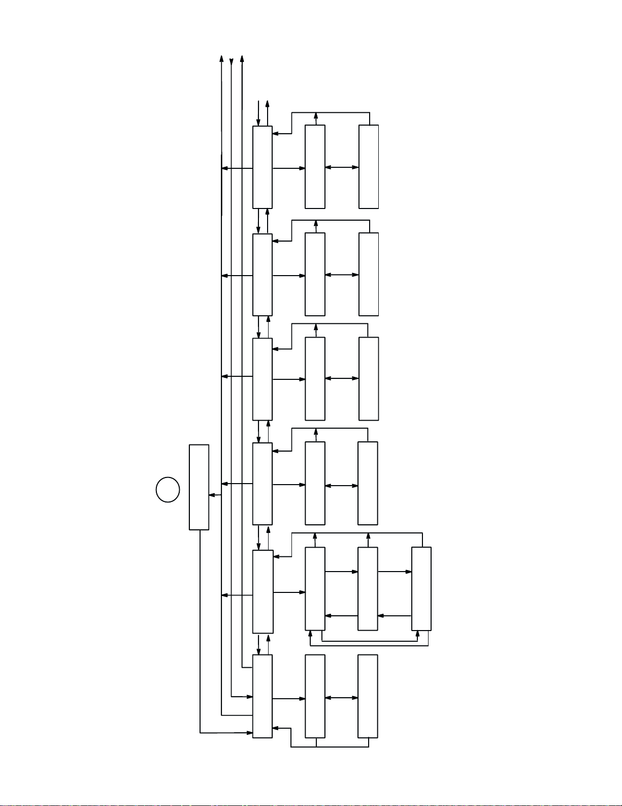
Continued
on sheet 6
P
U
N
P
N
U
*
D
U
N or P
2
C
FROM SHEET
APPLICATION
COMPATIBILITY
D
ALARM ON FAULT
P
N
UU
POWER ON STATE
ALARM ON FAULT
U
POWER ON STATE
U
ENABLE
*
ON LINE
N or P
ALARM ON FAULT
U
POWER ON STATE
U
DISABLE
OFFLINE
*
ADV
DD
PAPER ADV ANCE SW
PAPER ADV ANCE SW
NN
(1)
UU
D
PRINTER SELECT
N
PAPER ADV ANCE SW
PRINT + PAP
U
N or P N or P
*
PRINTER SELECT
DISABLE
U
*
N
MOVE PAPER ONLY
U
PRINTER SELECT
ON=DC1 / OFF=DC3
U
N
U
(1) Menu available inSerial Matrix protocol
Control Panel Configuration Diagram (sheet 5 of 17)
U
BUFFER SIZE
PP P P
N
P
DD
U
PRINTER PROTOCOL
BUFFER SIZE
PRINTER PROTOCOL
U
P
2048 CHARACTERS
P
*
P–SERIES
BUFFER SIZE
N or P
PRINTER PROTOCOL
U
P
512 CHARACTERS
SERIAL MATRIX
BUFFER SIZE
1024 CHARACTERS
N
Configuration 3–15
Page 56

UNP
sheet 7
Continued on
P
N
U
(1)
*
U
U
U
P
P
N
80–9F HEX
N
(1)
SELECT SFCC CONTROL CODE 06
D
D
D
N or P
CONTROL CODE 06
8.0 LPI
U
*
N or P
CONTROL CODES
80–9F HEX
U
*
N
P
01 SOH
SELECT SFCC
P
10.3 LPI
CONTROL CODE 06
U
80–9F HEX
PRINTABLE
U
03 ETX
SELECT SFCC
U
N
P
SELECT SFCC
1B ESC
N
P
U
N
5E HAT
SELECT SFCC
P
(1) Menu available in P–Series protocol
U
SELECT SFCC
7E TILDE
sheet 5
Continued from
UUN
P
N
U
U
U
N
*
U
UNIDIRECTIONAL
P
N
D
P
DISABLE
UNIDIRECTIONAL
N
UNIDIRECTIONAL
N
P
P–SERIES PLOT
P
ENABLE
UNIDIRECTIONAL
N
Control Panel Configuration Diagram (sheet 6 of 17)
*
DU
U
SHUTTLE TIMEOUT
P
N
P
to
4 SECONDS
SHUTTLE TIMEOUT
Press N or P
increase/decrease
seconds in 5–second
4 seconds to
increments from
300 seconds
Configuration3–16
Page 57

U
U
UDISPLAY LANGUAGE
UDISPLAY LANGUAGE
*
U
P
P
P
U
D
DISPLAY LANGUAGE
N
D
OVERSTRIKE
N
N
(1)
D
CONTROL CODE 08
ENGLISH
DISPLAY LANGUAGE
P
U
*
N or P
ENABLE
OVERSTRIKE
U
*
N or P
DOUBLE HIGH
CONTROL CODE 08
N
P
DISPLAY LANGUAGE
UOVERSTRIKE
UCONTROL CODE 08
GERMAN
DISABLE
BACKSPACE
N
P
FRENCH
N
P
SPANISH
N
Control Panel Configuration Diagram (sheet 7 of 17)
P
P
UUN
sheet 6
Continued from
N
(1) Menu available in P–Series protocol
Configuration 3–17
Page 58
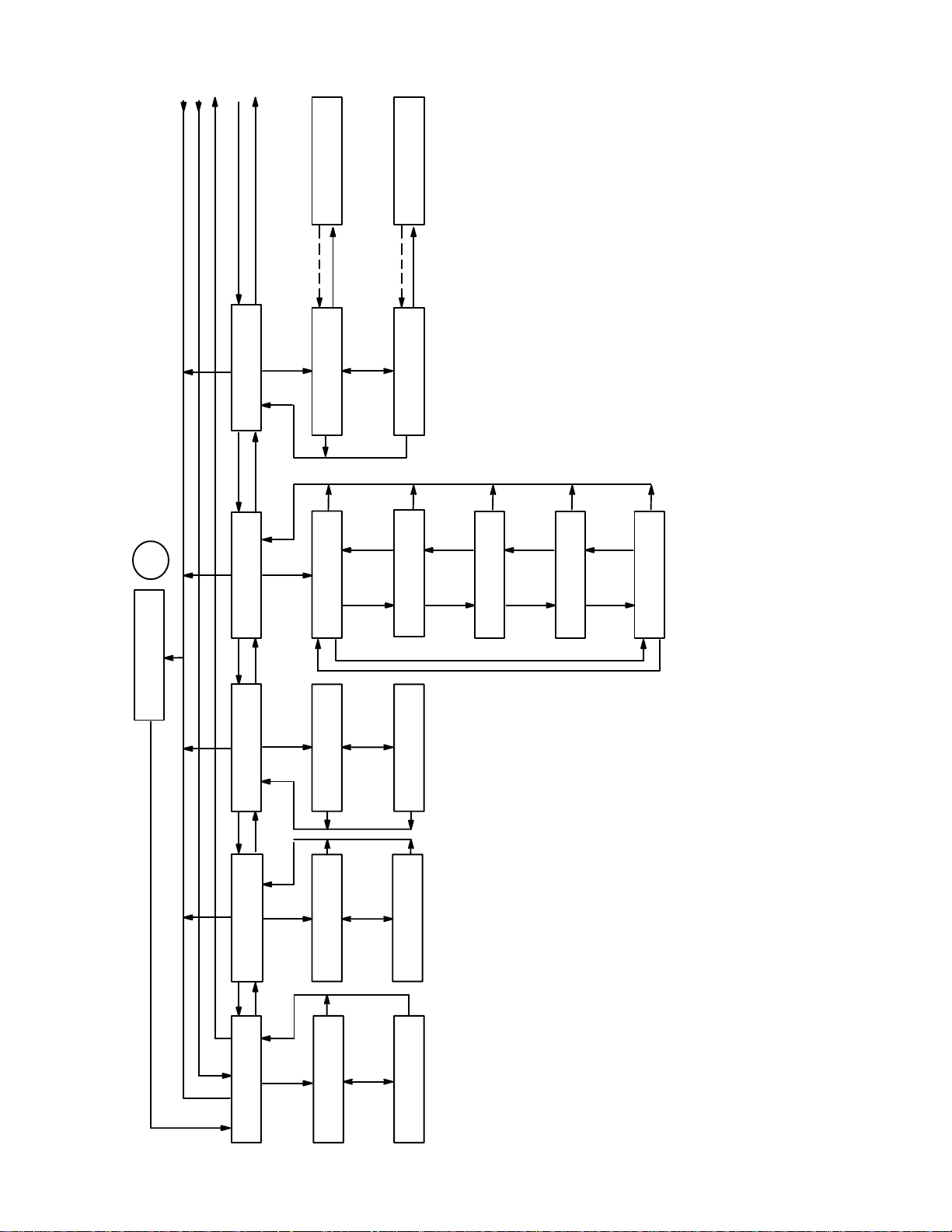
Continued
on sheet 9
U
N
P
2
FROM SHEET
D
P
U
VFU TABLE
P
VFU SELECT
CLEARED
VFU TABLE
N
(2)
D
U
(2)
(3)
CLEAR
VFU TABLE
U
U
VFU SELECT
EVFU
E
N or P
N
P
SAVED
VFU TABLE
(3)
SAVE
VFU TABLE
U
VFU SELECT
DVFU
E
(3) Returns after 1 second
(1) Menu available in Serial Matrix protocol
(2) Menu available in P–Series protocol
U
VFU SELECT
CVFU
PN
U
VFU SELECT
DISABLE
PN
N
P
U
VFU SELECT
NVFU
P
PAPER FORMAT
D
(1)
DD
U
DEFINE LF CODE
P
P
**
N or P
LF = LF
DEFINE LF CODE
LF = CR + LF
DEFINE LF CODE
N
Control Panel Configuration Diagram (sheet 8 of 17)
U
N or P
UU U
P
P
U
D
DEFINE CR CODE
NNN N
U
D
AUTO LINE FEED
*
DEFINE CR CODE
CR = CR
*
N or P
AUTO LINE FEED
AFTER FULL LINE
DEFINE CR CODE
CR = CR + LF
AUTO LINE FEED
DISABLE
Configuration3–18
Page 59
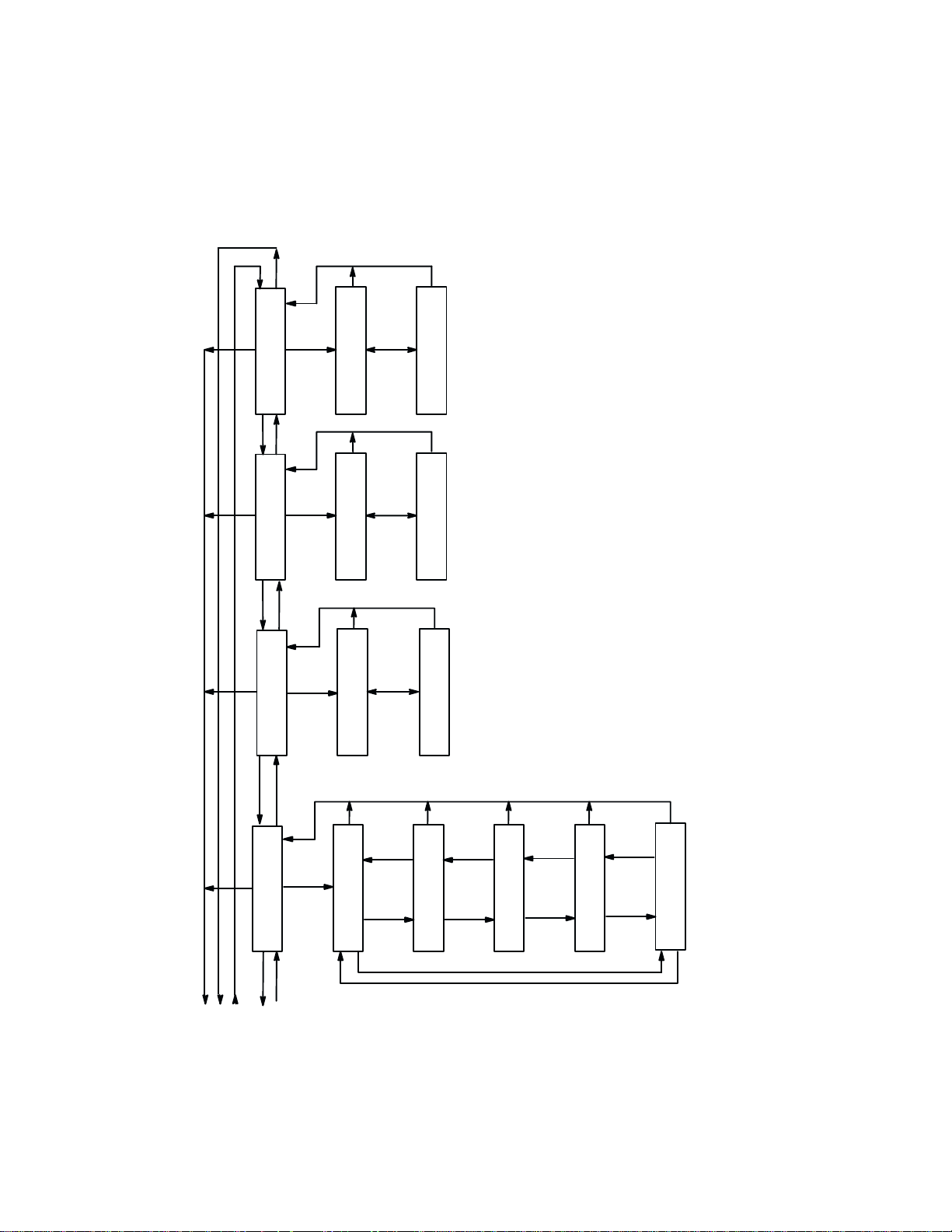
P
N
U
N or P
U
D
*
PRINT WIDTH
P
U
PMD FAULT
P
U
PAPER OUT
P
U
PRINT WIDTH
13.2
N
U
D
PMD FAULT
ENABLE
N
U
N or P
8.0
PRINT WIDTH
DISABLE
PMD FAULT
boxes displayed. If the P–Series protocol EVFU, NVFU, or CVFU is enabled and
loaded, then DISABLED BY VFU will be displayed.
(1) If a DVFU is enabled and loaded, then DISABLE and ENABLE will be the only menu
**
N or P
D
PAPER OUT
PAPER OUT
END OF PAPER
U
N
(1)
IMMEDIATE
N
N
N
Control Panel Configuration Diagram (sheet 9 of 17)
*
D
PERFORATION SKIP
5/6 INCH
P
PERFORATION SKIP
1 INCH
N
sheet 8
Continued from
UNN
P
PERFORATION SKIP
P
DISABLE
P
P
PERFORATION SKIP
PERFORATION SKIP
N
1/2 INCH
P
PERFORATION SKIP
2/3 INCH
P
Configuration 3–19
Page 60

U
N
P
N
U
N
*
SHEET 12
FOR SERIAL
RS–232 MENUS
I
*
N or P
D
D
STROBE POLARITY
STANDARD
U
ENABLE
FAST BUSY
U
STANDARD
RESP. POLARITY
STROBE POLARITY
P
N
FAST BUSY
N
D
RESP. POLARITY
PP
STROBE POLARITY
FAST BUSY
N or P N or P
RESP. POLARITY
INVERTED
DISABLE
INVERTED
U
D
LATCH DATA ON
N
LATCH DATA ON
N or P
LEADING EDGE
LATCH DATA ON
TRAILING EDGE
2
E
FROM SHEET
HOST INTERFACE
1
1
H
SHEET
FOR DATAPRODUCTS MENUS
NN
*
UU U
D
D
HOST INTERFACE
CENTRONICS
PPP
***
DATA POLARITY
P
STANDARD
DATA POLARITY
*
UU U U U
DD
PI LINE
P
NNNN
U
8
D
DATA BIT
P
DISABLE
PI LINE
UUU
*
DATA BIT 8ENABLE
N or P
N or P N or P
INVERTED
DATA POLARITY
ENABLE
PI LINE
DATA BIT 8DISABLE
Control Panel Configuration Diagram (sheet 10 of 17)
Configuration3–20
Page 61

N
U
*
N or P
D
LATCH DATA ON
P
N
UU
D
STROBE POLARITY
P
N
D
RESP. POLARITY
LEADING EDGE
LATCH DATA ON
U
*
STANDARD
STROBE POLARITY
STANDARD
RESP. POLARITY
LATCH DATA ON
N or P
STROBE POLARITY
RESP. POLARITY
TRAILING EDGE
INVERTED
INVERTED
**
D
DATA POLARITY
PP
STANDARD
DATA POLARITY
UU U
INVERTED
DATA POLARITY
Control Panel Configuration Diagram (sheet 11 of 17)
FROM SHEET 10
H
P
UU U U
D
HOST INTERFACE
DATAPRODUCTS
Configuration 3–21
D
PI LINE
P
NNN
8
D
DATA BIT
DISABLE
PI LINE
U
**
DATA BIT 8ENABLE
N or P N or P N or P N or P
PI LINE
ENABLE
DATA BIT 8DISABLE
Page 62
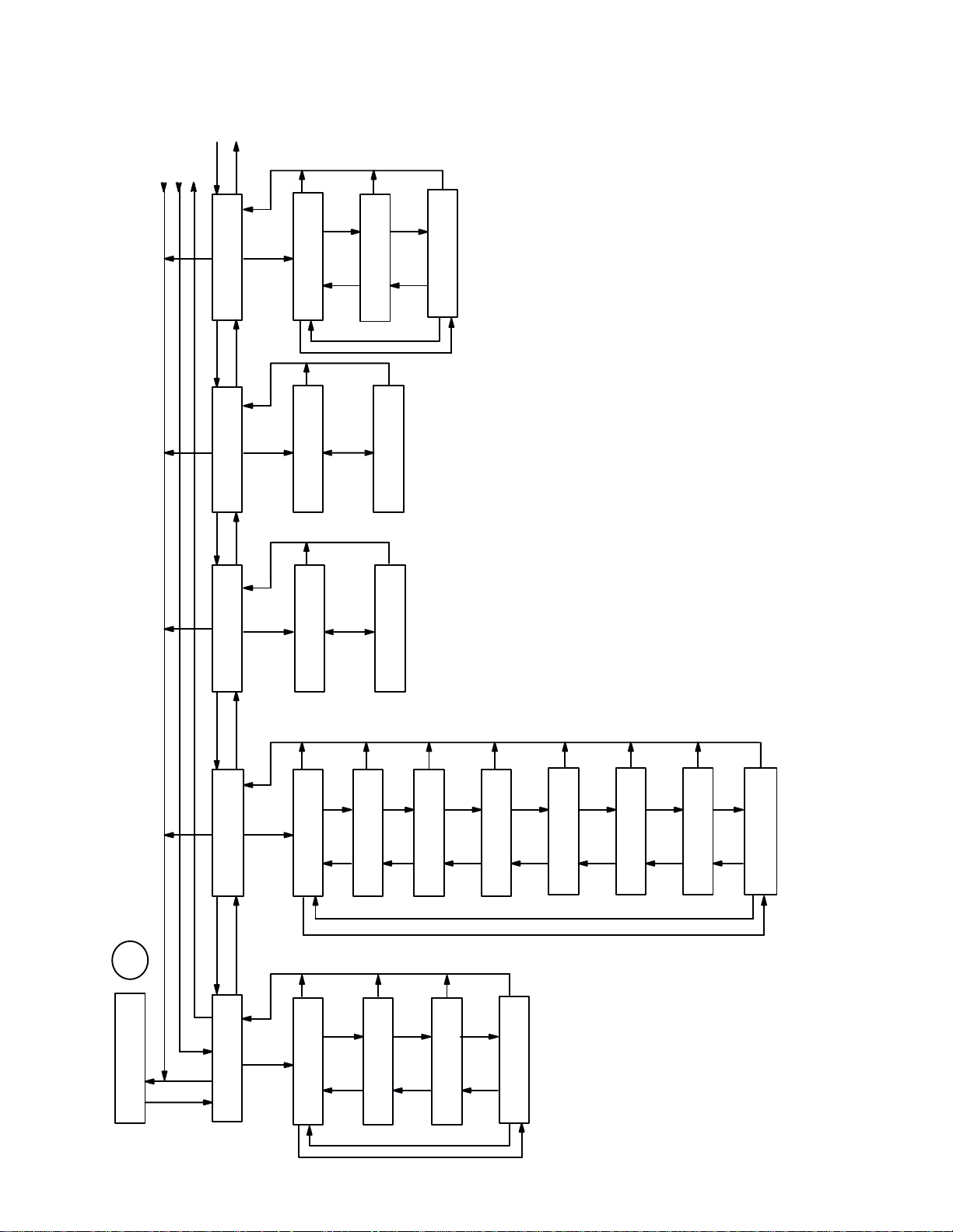
Continued
on sheet 13
U
N
P
P
N
U
N
**
PN
PARITY
N
STOP BIT
DD D
WORD LENGTHDATA PROTOCOL
PPP
PARITY
NONE
P
ONE
STOP BIT
*
8 BITS
WORD LENGTH
PARITY
N or P
N or P
ODD
STOP BIT
WORD LENGTH
P
TWO
7 BITS
N
PARITY
EVEN
I FROM SHEET 10
HOST INTERFACE
SERIAL RS–232
UUU
UUUU
P
P
U
D
D
DATA RATE
NNN
DATA RATE
P
U
D
DATA PROTOCOL
P
N
P
150 BAUD
N
*
P
X–ON / X–OFF
300 BAUD
DATA RATE
DATA PROTOCOL
N
P
N
P
ACK / NAK
600 BAUD
DATA RATE
DATA PROTOCOL
ETX / ACK
N
N
N
*
P
DATA RATE
N
P
P
1200 BAUD
DTR, RC, OR RTS
DATA PROTOCOL
N
2400 BAUD
DATA RATE
P
PN
4800 BAUD
DATA RATE
PN
9600 BAUD
DATA RATE
DATA RATE
N
Configuration3–22
Control Panel Configuration Diagram (sheet 12 of 17)
19200 BAUD
Page 63
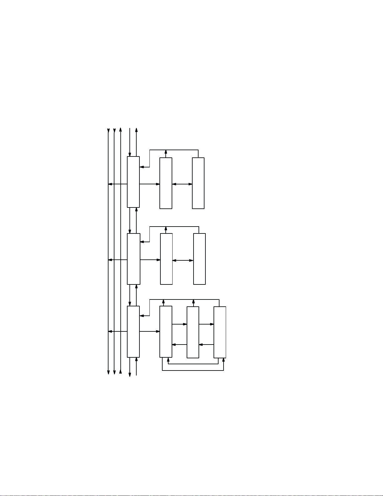
Continued
on sheet 14
PUN
P
N
UUU
CTS AND DSR
P
CD AND DSR
P
BIT 8 FUNCTION
P
D
N or P
*
DISABLE
CTS AND DSR
N
UU
D
N or P
CTS AND DSR
ENABLE
*
N
P
CD AND DSR
ENABLE
N
P
PI LINE
BIT 8 FUNCTION
IGNORE
BIT 8 FUNCTION
N
APPLICABLE displayed when appropriate)
Bit 8 will be received and acted on as a zero
(1) Not applicable for a 7–bit word (NOT
CD AND DSR
DISABLE
N
U
*
D
(1)
N
BIT 8 FUNCTION
P
FONT SELECT
Control Panel Configuration Diagram (sheet 13 of 17)
U
P
N
sheet 12
Continued from
Configuration 3–23
Page 64
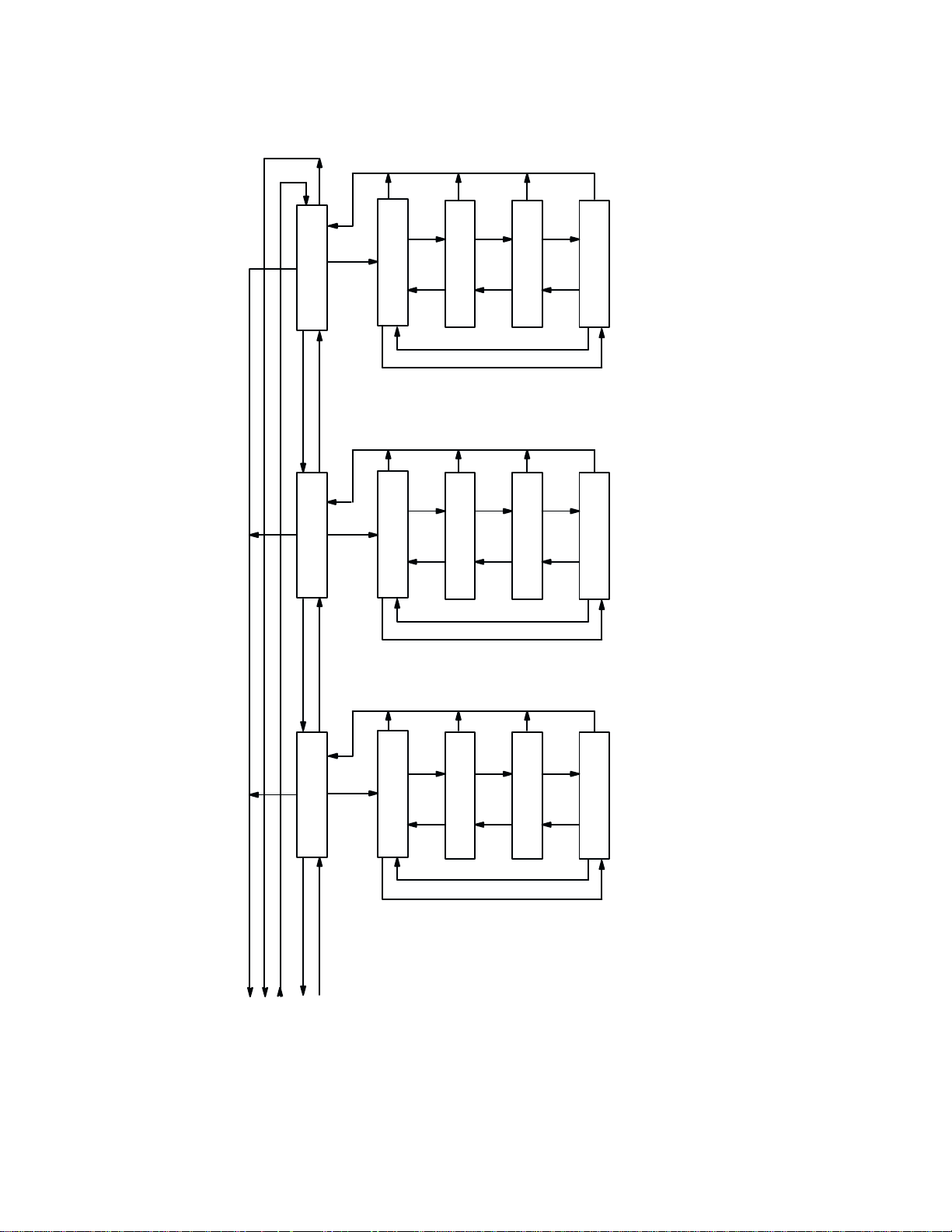
P
N
U
N
D
N
N
REVERSE CHANNEL
P
N
D
TO SEND
U U
REQUEST
P
N
REVERSE CHANNEL
ONLINE AND BNF
P
U
N
TO SEND
REQUEST
ONLINE AND BNF
P
P
REVERSE CHANNEL
OFFLINE OR BF
N
TO SEND
P
REQUEST
OFFLINE OR BF
P
FALSE
REVERSE CHANNEL
N
TO SEND
P
FALSE
REQUEST
P
REVERSE CHANNEL
TRUE
TO SEND
P
REQUEST
TRUE
BF = BUFFER FULL
BNF = BUFFER NOT FULL
U
TERM READY
DATA
P
PUN
sheet 13
Continued from
U
D
N
** *
TERM RDY
DATA
P
ONLINE AND BNF
P
TERM RDY
DATA
OFFLINE OR BF
N
N
P
N
TERM RDY
FALSE
DATA
P
N N N
TERM RDY
DATA
TRUE
Control Panel Configuration Diagram (sheet 14 of 17)
Configuration3–24
Page 65

N
P
N
P
U
PRINT STATISTICS
P
U
PRINTER TEST
FULL WIDTH
(1)
RS
U
BLACK PLOT
U
D
UU
J
SHEET 17
P
UU
PRINTER TEST PRINTER TEST
UNDERLINE ONLY BLACK PLOT
RS
UNDERLINE ONLY
PRINTER TEST
N
U
PRINTER TEST
N
RS
SHUT/RIBBON
P
RS
DEMO
(1)
RUNNING TEST
SHUT/RIBBON
RUNNING TEST
DEMO
2
FROM SHEET
G
DIAGNOSTICS
D
RS RS
DD
PRINTER TEST
8 INCH WIDTH
PP
NNN N
OL
UU
P
U
DU
PRINT DATASTREAM
IN HEX CODE
P
CONFIGURATION
PRINTOUT
OFF LINE
RS
CONFIGURATION
HEX DUMP
PRINTING
ON LINE
HEX DUMP
Returns after completion
of printout
UU
PPP
NNNN
RS
P
N
U U
P
RS
PRINTER TEST PRINTER TEST PRINTER TEST PRINTER TEST
SHIFT RECYCLE ALL E’S E PLUS TOF ALL H’S
E PLUS TOF ALL H’S
RUNNING TEST RUNNING TEST RUNNING TEST RUNNING TEST
ALL E’S
RUNNING TEST
RUNNING TEST
SHIFT RECYCLE
Control Panel Configuration Diagram (sheet 15 of 17)
Message SHUT/RIBBON FAST displayed in “FULL WIDTH” test
(1) Message SHUT/RIBBON SLOW displayed in “8 INCH WIDTH” test
Configuration 3–25
Page 66
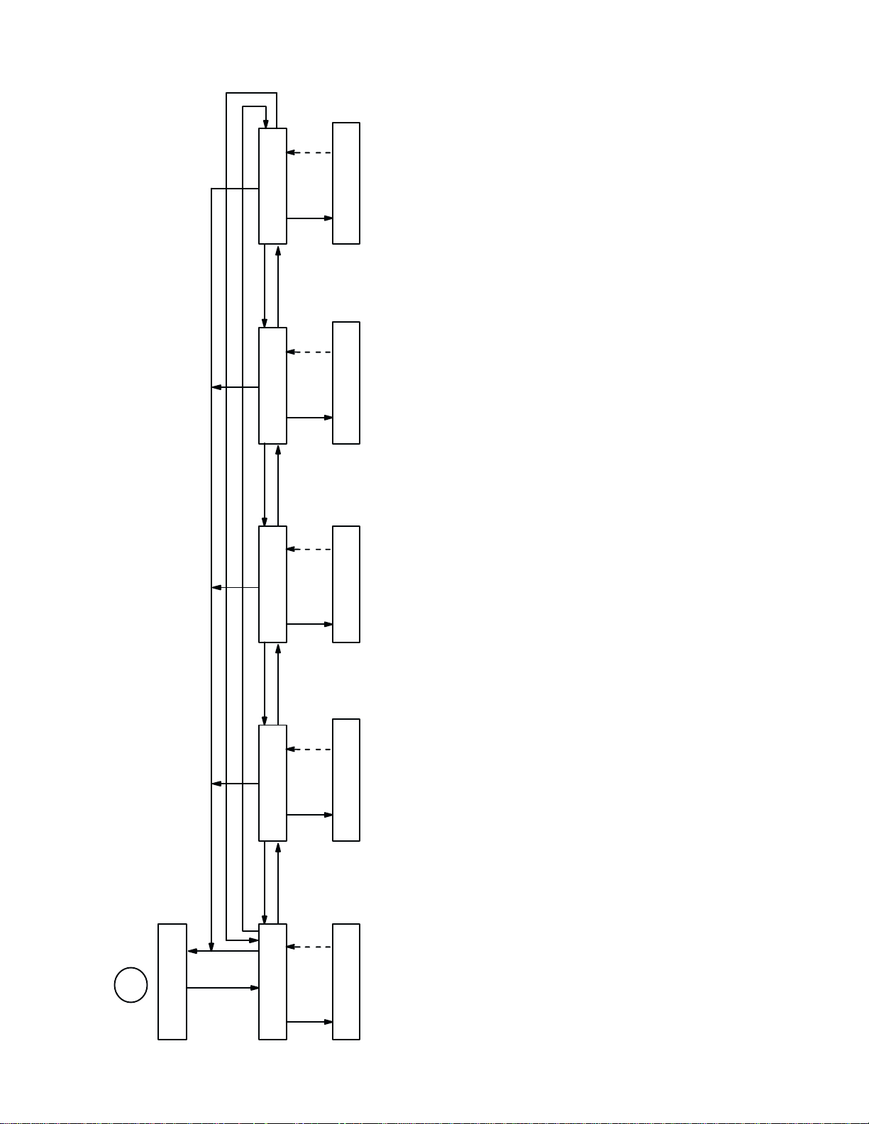
LOAD FACTORY
PARAMETERS
P
N
(1)
E
LOAD FACTORY
COMPLETED
Factory settings are indicated
by asterisks in the menu boxes
throughout this diagram
N
EE
PARAMETERSPARAMETERS
P
N
(1) (1)
LOAD IBM 3287 LOAD IBM 5225
P
N
UU U U
EE
PARAMETERS
Same as FACTORY PARAMETERS
except:
LOAD IBM 3287 LOAD IBM 5225
COMPLETED COMPLETED
Same as FACTORY PARAMETERS
except:
LOAD IGP
COMPLETED
Same as FACTORY PARAMETERS
except:
PI Line: Enable
80–9F Hex: Printable
Character Set: Multinational
Auto Line Feed: Disable
80–9F Hex: Printable
Character Set: Multinational
Auto Line Feed: Disable
Host Interface: Dataproducts
80–9F Hex: Printable
Character Set: Multinational
Auto Line Feed: Disable
(1) Returns after 1 second
Control Panel Configuration Diagram (sheet 16 of 17)
2
F
FROM SHEET
LOAD PARAMETERS
P
N
P
(1) (1)
U
D
PARAMETERS
LOAD SAVED LOAD IGP
COMPLETED
LOAD SAVED
User defined
Configuration3–26
Page 67

N
U
PRINT PAGES
N
PRINT LINES
XXXXXXXXXX XXXXXXXXXX
N
U
P
P
XXXXXXXXXX
SHUTTLE STROKES
P
N
U U
TIME
XXXXX.X HRS
PRINT
P
N
J
FROM SHEET 15
PRINT STATISTICS
U P
D
POWER ON TIME
XXXXX.X HRS
Control Panel Configuration Diagram (sheet 17 of 17)
Configuration 3–27
Page 68

Configuration3–28
Page 69

CHAPTER 4
GRAPHICS
Introduction
The
printer can produce bit image graphics when in Serial Matrix protocol, and P-Series Plot
Mode graphics when in P-Series protocol. You can print text and graphics on the same line
only by using the bit image protocol in Serial Matrix protocol. In either mode, printing text is
the default mode. Consequently, each line of graphics data must include the necessary plot
mode
commands to enable the printer to perform the desired graphics functions.
The following graphics information is presented in this chapter:
n
Serial Matrix Compatible Bit Image Graphics
n
P-Series Compatible Plot Mode
n
Combining Graphics and T
Serial Matrix Compatible Bit Image Graphics
ext
The printer produces bit image graphics in Serial
ated by printing a series of vertical bit image data bytes which represent the binary code bit
pattern.
These data bytes are actually the binary equivalent of ASCII character decimal values 0
through 255. When the data byte is rotated vertically, the result is a vertical data byte pattern
with
This method utilizes the 1" or true" bit from a binary data byte to print dot patterns.
the most significant bit (MSB) at the top.
Matrix protocol. Bit image graphics are cre
Plotting a Bit Image Pattern
A
Bit Image pattern can be produced by following these steps:
1. L
ay out the graphic(s) pattern to be printed on a quadrille pad or graph paper.
2. Determine the decimal equivalent of each bit image data byte required to produce the
pattern
3. W
4.
Enter and run the program on the host computer.
(Figure 4-1).
rite a program to generate the complete pattern.
Ć
4-1Graphics
Page 70
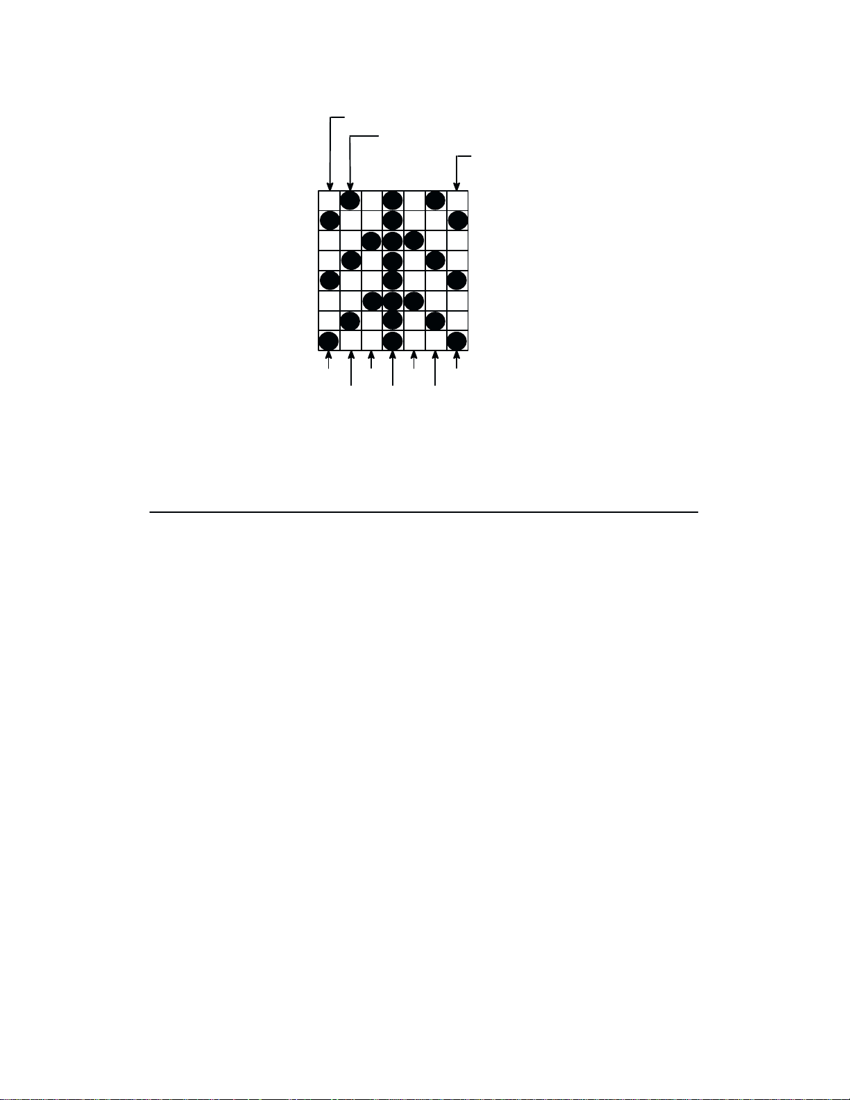
DECIMAL
WEIGHTS
128
1st BIT IMAGE DATA BYTE
2nd BIT IMAGE DATA BYTE
7th BIT IMAGE DATA BYTE
64
32
16
8
4
2
1
73
1463625536146
Figure 4-1. Bit Image P
73 DECIMAL
VALUES
attern Plan
How Bit Image Graphics Are Produced
The
binary data byte bit pattern for the A
Figure 4-2.
this data byte is rotated clockwise, the result is a vertical data byte pattern with the
D If
most
significant bit (MSB) at the top.
D If
each 1" or true bit is plotted, the result is a bit image plot of the A
A."
relationship of A
The
SCII
character, decimal value, and Bit Image plot is shown in Figure 4-3.
D The data bytes can be identified by their binary, octal, hexadecimal, or decimal
equivalents.
These are used to generate a Bit Image pattern.
D Bit Image plotting is not limited to printable ASCII characters; Bit Image patterns
can
be plotted for any 8-bit data byte with decimal values ranging from 0 to 255.
D
The standard A
SCII character chart and its equivalents is provided in Appendix A.
SCII character A" (hex 41, decimal 65) is pictured in
SCII character
NOTE:
cal
of adjacent graphics lines; however
Bit Image Graphics is recommended in the DP print mode (120 X 72 dpi). V
density variation in other print modes may cause white horizontal bars or overlapping
, changing the line spacing can correct this problem.
ertiĆ
Graphics4-2
Page 71

MSB
876 54321
8
7
6
5
4
3
2
1
MSB
MSB : Most Significant Bit
ASCII
CHARACTER
=A65=
Figure 4-3. Bit Image P
Bit Image Density
Figure 4-2. V
DECIMAL
VALUE
ertical Data Byte P
BINARY
CODE
EQUIVALENT
128
TO
attern
VERTICALLY
ROTATED DATA
MSB
64
32
16
8
4
2
1
attern from an ASCII Character
BYTE
BIT IMAGE
PATTERN
=
Bit
image graphics may be printed in different dot densities. Dot densities are selected by con
trol
code:
D
Control code ESC K
Single
Density bit image
selects the
Single Density Mode.
graphics in the Data P
rocessing print mode are printed at 60
dots per inch (dpi) horizontally and 72 dpi vertically. In the Correspondence print
mode, the horizontal dot density is 90 dpi and vertical dot density is 96 dpi. In the
High
Speed (HS) mode, horizontal dot density is 60 dpi and vertical dot density is 48
dpi.
D Control
code ESC L
selects the
Double Density Mode.
The Double Density mode prints up to twice the number of dots per inch horizonĆ
tally in the same space as used for Single Density. The vertical dot density remains
Ć
4-3Graphics
Page 72

the
same as in the Single Density mode. Double horizontal density requires twice the
number
ing
D
Control code ESC Y
When the Double Density, Double Speed control code is received, the data will be
printed at double the current horizontal dot density, but adjacent dots are not
printed. Since Double Density graphics are printed at half speed, Double Speed,
Double
ics.
D Control
When printing Quadruple Density graphics, the printer pairs adjacent quadruple
density
mode.
of input data bytes to print
double density reduces the printing speed by half.
selects the
Density graphics
code ESC Z
bit image bytes. The compounded data is then printed in the Double Density
are printed at the same speed as are Single Density graph
selects the
Bit Image Programming Format
The
general Bit Image expression is:
ESC CC(n1)(n2)DATA
where:
the same length line as for Single Density. P
Double Speed, Double Density Mode.
Quadruple Density Mode.
rintĆ
Ć
ESC =
CC =
n1, n2
DATA =
D
The syntax of the Bit Image expression must be correct.
D The expression must include the appropriate dot density control code, the number
of
D
The number of data bytes and the n1, n2 definition must be equal.
D Any characters following n1 and n2 will be interpreted and plotted as data until the
n1,
D
If n1 = n2 = 0, then control codes K, L, Y, or Z are ignored.
n2 = 700/256 = 2
n1 = 700-(2x256) = 700-514 = 188
The program statement is: ESC K (188)(2)(D
NOTE:
statement within the BASIC program.
=
bytes of data to be plotted, and the data itself.
n2 definition is satisfied.
Depending on the host computer system, it may be necessary to include a width
the Serial Matrix compatible header
K, L, Y or Z to select dot density
(K=single, L=double, Y=double-density, double speed
Z=quadruple density)
n1 + 256 n2 defines the number of data bytes to follow
the dot pattern bytes
ATA )
D The
maximum number of data bytes that can be included in the DATA portion of the
program statement (when using 132 column paper) varies according to the
mode:
operating
Graphics4-4
Page 73

At
60 dpi, Single Density = 792 bytes;
Double Density = 1584 bytes
Quadruple Density = 3168 bytes
D Data
A detailed description of the individual bit image control codes with examples is provided in
the
P
rogramming chapter.
in excess of the right margin is discarded. If the
excess of the right margin will cause a Line Feed (LF) and continue printing on the
next
line.
auto line feed is enabled, data in
Bit Image Sample Program
The
following sample program written in BA
the
pattern shown in Figure 4-1. The 7 data bit pattern is repeated 40 times. The printed result
of
running the program is shown in Figure 4-4.
SIC produces Single Density bit image graphics of
10 LPRINT ”Single Density Bit Image Graphics
20 LPRINT CHR$(27);
30 FOR N=1 TO 40
40 RESTORE
50 FOR I=1 TO 7
60 READ R
70 LPRINT CHR$(R);
80 NEXT I
90 NEXT N
100 DATA 73, 146, 36, 255, 36, 146, 73
110 LPRINT
Figure 4-4. Sample Single Density Bit Image Graphics
”K”;CHR$(24);CHR$(1);
P-Series Compatible Plot Mode
”
P-Series compatible odd/even dot Plot Mode is available only in P-Series printer protocol.
Plot
Mode allows any individual dot position to be addressed and printed. This
ety of graphics, including bar codes, complex curve graphs, pie and bar charts,
or
halftones.
produces a vari
block
characters,
Plot Density
Plot
density refers to the number of dots per inch (dpi) printed in a single
plot
density are available with P-Series Plot Mode graphics: normal density
ty.
dot row. T
and double densi
wo types of
Ć
Ć
4-5Graphics
Page 74

In
Normal Density Plot
D
The mode is selected with the odd dot plot control code ENQ (05 hex).
D The
odd-numbered dot columns are addressed to produce a horizontal and
density
:
vertical
that varies, based on the mode of operation:
Print Mode
Data Processing (DP)
Correspondence (NLQ)
High Speed A (HS)
High Speed B (HSB)
High Speed C (HSC)
D
Different print modes cannot be mixed on the same dot row.
Figure 4-5 illustrates normal density dot plot.
Figure 4-5. Normal Density Plot
Horizontal dpi Vertical dpi
60
90
60
60
60
72
96
48
72
72
In
Double Density Plot:
D Two separate shuttle strokes produce double density plot. First the even plot comĆ
mand
(EOT
, 04 hex) and
05
hex) and dot data, allowing a maximum of 1584 dots in a single dot row at 60 dpi.
D Even dot plot is sent first for control of the initial plot pattern; then odd dot plot is
sent
for control of the final dot pattern.
D
The dots average .017" in diameter.
D
The vertical density remains the same in normal and high density plotting.
Figure 4-6 illustrates double density plotting.
dot data are sent, followed by the odd plot command (ENQ,
Figure 4-6. Double Density Plot
Graphics4-6
Page 75
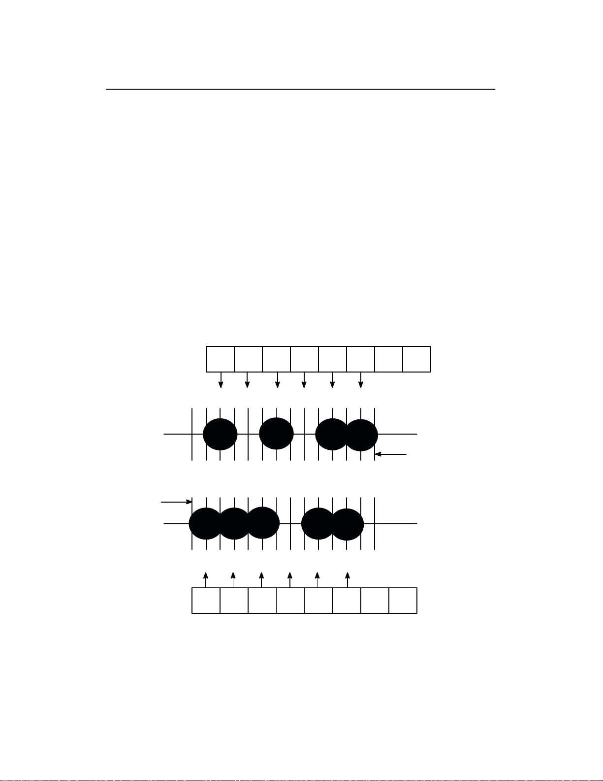
Plot Data Byte Format
In
P-Series Plot Mode, the format is as follows:
D
Each data byte specifies six out of twelve dot columns.
D Using
D
D
D The binary equivalent of the plot data bytes must be known to accurately address
As shown in Figure 4-7, a dot is printed at the location addressed by each of bits
data byte that is set (1 or true).
odd dot plot mode, bits 1 to 6 of the data byte address the odd-numbered dot
columns; using even dot plot mode, bits 1 to 6 of the data byte address the evennumbered
dot columns.
Bit 6 and/or bit 7 of the data byte must be a 1" (or true) bit in the Plot mode.
Bit 8 of the data byte is not used in the Plot mode and may be either a 1 or 0.
specific
dot positions.
1 to 6 in the
NOTE: Bit order in this example is reversed.
EVEN DOT PLOT DATA BYTE
LSB MSB
BIT 1 BIT 2 BIT 3 BIT 4 BIT 5 BIT 6 BIT 7 BIT 8
NOT
00 01111
USED
NOTE: BIT 6
AND/OR BIT 7
MUST BE 1"
FOR PLOT MODE
DOT COLUMN
#12 OF PREVIOUS
CHARACTER
COLUMN
2 4 6 8 10 12
1357911
111 1110
BIT 1 BIT 2 BIT 3 BIT 4 BIT 5 BIT 6 BIT 7 BIT 8
LSB MSB
ODD DOT PLOT DATA BYTE
DOT COLUMN #1 OF
NEXT CHARACTER
COLUMN
NOTE: IN ACTUAL
PRINTING, THESE
TWO ROWS MERGE
TO PRINT ON THE
SAME ROW.
NOT
USED
Figure 4-7. P-Series Plot Data Byte F
ormat
4-7Graphics
Page 76

Plot Data Line Format
A
plot data line may contain any number of plot data bytes up to the maximum of 132 for hori
zontal
dot density of 60
90
dpi (Correspondence mode). If Auto Line F
lost.
If the maximum is exceeded and A
the
remaining plot data is printed as text on the next line.
The plot mode control code may occur anywhere in the line prior to the line terminator, but
plot
speed may decrease if it is not at the beginning of the line.
NORMAL DENSITY PLOT
For
normal density plot, the plot line contains: Control Code 05 hex, plot data bytes, and a Line
T
erminator (0A hex or 0C hex). The control sequence for sending
ty
Plot
is as follows:
1.
Send the plot command code ENQ (05 hex).
2.
Send the plot data bytes (refer to NO T
3. Send a line terminator, either a Line Feed (LF, 0A hex) or a Form Feed (FF, 0C hex). A
Carriage Return (CR) may also be used instead of the LF code, provided the Carriage
Return
CR + LF).
has been configured for Carriage R
dpi (Data P
rocessing mode) or 198 bytes for a horizontal dot density of
eed is disabled, any bytes over the maximum are
uto Line F
eed is enabled, a Line F
the
AG on page NO TAG).
eturn = Carriage R
eed (LF) is forced and
P-Series
eturn + Line F
Normal Densi
eed (CR
=
Ć
Ć
a. A
line feed (0A hex) used as the line terminator causes the contents of the buffer to
be plotted and the paper advances a single dot row, based on the vertical density of
current mode.
the
b. A
form feed (0C hex) used
be
plotted and the paper to advance to the
of
4. Regardless
selected
NOTE
DOUBLE DENSITY PLOT
For double density plot, the plot line contains: Control Code 04 hex, plot data bytes, a Line
Terminator (0A hex or 0C hex), Control Code 05 hex, plot data bytes, and a Line Terminator.
The
control sequence for sending P-Series
1. Send the even dot plot control code EOT (04 hex), followed by plot data bytes (refer to
NO TAG on page NO TAG).
2. Send a line terminator, which causes the printer to plot the data bytes; the paper is not
advanced
plot
data bytes.
which line terminator code is sent, the printer will default to the previously
print mode unless further plot control codes are provided with the data.
: F
ailure to adhere to this format may cause unexpected results.
in Double Density Plot; the printer now waits for the second plot command and
as the line terminator causes the contents of the buffer to
top of the next form.
Double Density Plot is as follows:
Graphics4-8
Page 77

3. Send
line
a. A
b. A
the odd dot plot control code ENQ (05 hex) and a
terminator.
line feed (0A hex) used as the line terminator causes the contents of the buffer to
be plotted and the paper advances a single dot row, based on the vertical density of
current mode. A CR (if CR = CR + LF is configured) may also be used with
the
same
result.
form feed (0C hex) used as the line terminator causes the data bytes to be plotted
and
the paper to advance to the
top of the next form.
second line of data, followed by a
the
4. Regardless
selected
NOTE
print mode unless further plot control codes are provided with the data.
: F
of
which line terminator code is sent, the printer will default to the previously
ailure to adhere to this format may cause unexpected results.
4-9Graphics
Page 78

Plotting the Data
P-Series
Plot Mode plots the image from the horizontal
bit pattern. Figure 4-8 duplicates the
pattern shown in Figure 4-4 but is modified for Odd Dot Plot. Eight dot rows are required,
two characters per row, six columns per character. (The dots required to produce the pattern
are
shown in NO T
DOT
ROW
AG on page NO TAG.)
1st
CHARACTER
ODD COLUMNS
13 11579 13 11579
1
2
3
4
5
6
7
8
ODD COLUMNS
Figure 4-8. Odd Dot Plot P
2nd
CHARACTER
1st
CHARACTER
ASCII DECIMAL
*
|
\
*
|
\
*
|
attern Plan
42
73
92
42
73
92
42
73
2nd
CHARACTER
ASCII DECIMAL
@
A
@
@
A
@
@
A
64
65
64
64
65
64
64
65
The following program uses the Odd Dot Plot control code to produce the image.
10 LPRINT ”Odd Dot Plot
”
20 FOR I=1 TO 8
30 READ R1
40 READ R2
50 LPRINT CHR$(5);
60 FOR N=1 TO 25
70 LPRINT CHR$(R1);CHR$(R2);
80 NEXT N
90 LPRINT
100 NEXT I
110 DATA 42, 64, 73, 65, 92, 64, 42, 64, 73, 65, 92, 64, 42, 64, 73, 65
120 LPRINT
D
The image is printed 25 times as shown in Figure 4-9.
D An
entire dot row is plotted in one
printing pass. Consequently, the first row of all 25
images is printed in one pass, followed by the second row, etc, until all rows have
printed.
been
Figure 4-9. Sample Odd Dot Plot
Graphics4-10
Page 79

1 3 5 7 9 11
2 4 6 8 1012
Printronix
BINARY OCT HEXDEC ASCII
1 3 5 7 9 11
2 4 6 8 1012
i
j
‘
a
c
b
f
e
g
d
h
l
m
nop
k
q
t
r
s
u
v
w
z
{
x
y
}
606162636465666768696A6B6C6D6E6F707172737475767778797A7B7C7D7E
96
97
98
99
100
101
102
103
104
105
106
107
108
109
110
111
112
113
114
115
116
117
118
119
120
121
122
123
124
125
140
141
142
143
144
145
146
147
150
151
152
153
154
155
156
157
160
161
162
163
164
165
166
167
170
171
172
173
174
175
1100000
1100001
1100010
1100011
1100100
1100101
1100110
1100111
1101000
1101001
1101010
1101011
1101100
1101101
1101110
1101111
1110000
1110001
1110010
1110011
1110100
1110101
1110110
1110111
1111000
1111001
1111010
1111011
1111100
1111101
@
I
F
B
A
E
C
D
G
J
L
H
K
M
N
OPQ
S
T
R
U
VWX
Y
\
[
Z
]
404142434445464748494A4B4C4D4E4F505152535455565758595A5B5C5D5E
64656667686970717273747576777879808182838485868788899091929394
100
101
102
103
104
105
106
107
110
111
112
113
114
115
116
117
120
121
122
123
124
125
126
127
130
131
132
133
134
135
~
126
176
1111110
^
136
__
Delete
7F
127
177
1111111
5F
95
137
Table 4–1. Plot Data Byte Dot Patterns
BINARY OCT HEXDEC ASCII
1000000
1000001
1000010
1000011
1000100
1000101
1 3 5 7 9 11
2 4 6 8 1012
!
Space
”#$
%&’()
20320402122232425262728292A2B2C2D2E2F303132333435363738393A3B3C3D3E
33343536373839404142434445464748495051525354555657585960616263
041
042
043
044
045
BINARY OCT HEXDEC ASCII
0100000
0100001
0100010
0100011
0100100
0100101
1000110
046
0100110
1000111
047
0100111
1001000
1001001
1001010
050
051
052
0101000
0101001
0101010
1001011
*+,
053
0101011
1001100
054
0101100
1001101
–
055
0101101
1001110
.
056
0101110
1001111
/
057
0101111
1010000
1010001
1010010
0
1
2
060
061
062
0110000
0110001
0110010
1010011
1010100
3
4
063
064
0110011
0110100
1010101
1010110
1010111
5
6
7
065
066
067
0110101
0110110
0110111
1011000
8
070
0111000
1011001
9
071
0111001
1011010
:
072
0111010
1011011
;
073
0111011
1011100
<
074
0111100
1011101
=
075
0111101
1011110
>
076
0111110
4–11Graphics
1011111
?
3F
077
0111111
Page 80

To Exit the P-Series Plot Mode
When
returning to the print mode from the P-Series Plot Mode, an extra line feed should
included
plot graphics. If the extra line feed is not included, the first character line after the graphics
data
in the data stream to maintain proper print line registration relative to the last line of
may be truncated, as shown in Figure 4-10.
plot data plot data
@ABCDEFGHIJKLMNOPQR
@ABCDEFGHIJKLMNOPQR
be
In this example, a text line follows
plot data, preceded by a single line
terminator code. (T
extend into the range of the previ
ously printed plot line and appear
truncated.)
ext characters
Figure 4-10. Truncated Character Line
Combining Graphics and Text
The printer can combine Serial Matrix bit image graphics and characters (text) on the same
line.
P-Series graphics and printable symbols cannot be intermixed on the same line.
This example shows a text line following plot data, but preceded by an
additional
Ć
(Characters are able to be printed
full-height.)
line terminator code.
Graphics4-12
Page 81

VERTICAL FORMAT UNITS
Introduction
The
P9012 printer includes four vertical
ormat Unit (EVFU), 2) Dataproducts Direct A
F
Access Vertical Format Unit (NVFU), and 4) Centronics Direct Access Vertical Format Unit
(CVFU).
Matrix protocol. All VFUs are available only in P-Series protocol and are enabled from the
control
tocol.
Although
panel, and the Serial Matrix vertical
This chapter describes:
n
General VFU P
n EVFU n CVFU
n DVFU n
General VFU Programming
not a true" VFU, a vertical tab table is provided for forms control in Serial
rogramming n NVFU
CHAPTER 5
format units: 1)
ccess V
tabs feature is always enabled in Serial Matrix pro
Printronix
ertical F
Serial Matrix V
standard Electronic V
ormat Unit (D
ertical F
VFU), 3) Direct
ormatting
ertical
Ć
A
vertical format unit provides an efficient way to slew paper rapidly during repetitive printing
tasks. The type of VFU used is a configuration option selected from the control panel. If not
the VFU option should be disabled from the control panel.
used,
The general VFU programming procedure is as follows:
1.
Design a form, determining spacing and channel assignments for each line.
2.
Send the programming sequence to the host. The sequence depends on the type of VFU
used.
Some VFUs require the PI line normally associated with the Dataproducts parallel interface.
that data bit 8 of the standard RS-232 interface can be configured for use as the PI line.
Note
The
following information applies when programming and using a V
Elongated Characters - Elongated (double high) characters can be used within VFU proĆ
The VFU automatically counts one line of elongated characters as two normal charac
grams.
ter lines.
P
aper R
unaway P
sent from the host computer, the printer will move the paper a single line feed. If the VFU is
selected
of
Line Spacing - The printer can use any line spacing with the VFU. The VFU determines the
forms length according to the program specifications and the currently selected line spacing.
and
the assigned sequence currently in memory, will move the paper a single line feed.
rotection
the memory has been loaded, a channel code sent from the host, which is not a part
- If the VFU is selected but not loaded when a VFU command is
ertical F
ormat Unit:
Ć
5-1Vertical Format Units
Page 82

Line
spacing may be mixed on the same form, but should be done with caution to avoid
dictable
VFU Deselected - If any VFU is deselected from the control panel, the VFU data is ignored
and the forms length definition returns to the previously set value. The current print position
becomes
results.
the top-of-form.
unpre
VFU Load/Save/Clear
One
VFU table can be saved
is: VFU type, LPI, and VFU channel data.
mat
Load - Upon printer powerup or printer reset, a previously saved VFU will be loaded if the
VFU table
saved
to
the value stored in the VFU table if the saved VFU was loaded using the 6 or 8 lpi D
NVFU
Save - From the control panel, VFU TABLE SAVE writes the current VFU table into
Non-Volatile
selection.
Clear
tion menu, control code (SFCC @), changing printer protocol, changing VFUs, loading paĆ
rameters, or by loading a new VFU format. When DIS
previously loaded VFU data is
Start L
-
The VFU can be cleared by pressing
matches the
oad code.
memory. Skip-over perforation and forms length values
in Non-V
VFU type
not
olatile Memory (NVM) at a time. The VFU table for
(see page 3-18). Upon loading the VFU, LPI will be set
ENTER at the VFU T
ABLE is selected as the VFU type, the
cleared and will still be in effect if reselected.
VFU
or
are not saved from this
ABLE CLEAR configura
Ć
Ć
Ć
P-Series EVFU
The
EVFU may be selected in P-Series protocol. The EVFU provides 16 channels to identify
up
to 192 lines. The programming sequence is 1) start load code; 2) line identification code; and
3)
end load code.
Start Load Code - 1E or 6E Hex
The
start load code clears and initializes the EVFU memory for
start
load code is 1E
(high).
Channel Assignment
The EVFU memory has the capacity for 192-line forms. The first line identification code
(channel
identification
cation code. Filler channel codes are used for lines that will not be accessed by the print proĆ
gram.
top-of-form, and channel code 12, which is reserved as the vertical tab channel. The same
filler
code) in the memory load program defines the first line on the form; the second line
Any channel code can be used as a filler except channel code 1, which is
channel code can be repeated as necessary for any number of lines.
the memory load program. The
hex when the PI line is disabled (low) or 6E hex when the PI line is enabled
code defines the second line on the form, etc. Each line must have a line identifi
reserved for the
Ć
Vertical Format Units5-2
Page 83

Channel 1 - The top-of-form code, reserved as the first line on the form or the first line
printed
to the top of the next form. After the memory is loaded, a Form Feed code (FF, 0C hex) will
move
(top-of-form position). The operating program sends the
the paper tothe next channel 1 (top-of-form).
channel 1 code to advance
Channels
or
filler channels. Each line on the form must be identified by a channel code. When the operat
ing program sends the channel code, the paper advances to the line identified by the channel
code. Lines not used by the operating program must be identified by filler channels (unused
channel
Channel
any
12 code. If channel 12 is not loaded in the EVFU memory, a single line feed will be executed
when
Channel 15 and 16 - Used as general channel codes or filler channels only when the VFU is
accessed
15
and 16 function as the Start L
2 through 11, 13 and 14
codes).
12
- R
eserved as the V
data in the print buffer and rapidly
a VT code is sent.
by the PI line. In an EVFU form that does not use the PI line, the codes for Channels
- Used as general channel codes (line identification codes)
ertical T
oad and End Load codes.
ab channel. The V
slews the paper to the next line identified by the channel
ertical T
ab code (VT
, 0B hex) prints
End Load - 1F or 6F Hex
The
end load code terminates the memory
PI
line
is disabled (low) or 6F hex when the PI line is high. Channel codes in excess of 192 chan
received prior to the end load code are discarded.
nels
load program. The end load code is 1F hex when the
Ć
Ć
Using the EVFU
Once the EVFU program has been enabled and loaded, the VFU LOADED
control
the buffer to
number
F
1.
2.
OR:
1.
2.
Given these conditions, the lower four bits of a byte will specify the EVFU channel number.
Table 5-1 lists the EVFU channels and their equivalent data bytes with the PI line enabled;
Table 5-2
panel lights. Sending the appropriate channel code to the printer will cause any data
print
and slew the paper to the next line on the form having the specified channel
assigned in EVFU memory.
or a data byte to be recognized as an EVFU instruction, the following criteria must be met:
PI line must be enabled and set high; and
Data bit 5 must be 0 (not set).
PI line must be disabled or low; and
Data bit 5 must be 1 (set).
lists the EVFU channel and their equivalent data bytes with the PI line disabled.
indicator on the
in
5-3Vertical Format Units
Page 84

Table 5-1. P-Series EVFU Codes - PI Line Enabled
ASCII Channel
Hex
Dec
00
01
02
03
04
05
06
07
08
09
0A
0B
0C
0D
0E
0F
6E
6F
10
11
12
13
14
15
110
111
X = Undefined, 0 or 1 1 = High 0 = Low
Code
0
NUL
1
SOH
2
STX
3
ETX
4
EOT
5
ENQ
6
ACK
7
BEL
8
9
BS
HT
LF
VT
FF
CR
SO
SI
PI 7 6 5 4 3 2 1
n
o
8
X
1
X
1
X
1
X
1
X
1
X
1
X
1
X
1
X
1
X
1
X
1
X
1
X
1
X
1
1
X
1
X
X
1
X
1
Data Bits
X
X
0
0
0
0
0
X
X
0
0
0
0
1
X
X
0
0
0
1
0
X
X
0
0
0
1
1
X
X
0
0
1
0
0
X
X
0
0
1
0
1
X
X
0
0
1
1
0
X
X
0
0
1
1
1
X
X
0
1
0
0
0
X
X
0
1
0
0
1
10
X
X
0
1
0
1
0
11
X
X
0
1
0
1
1
12 (VT)
X
X
0
1
1
0
0
13
X
X
0
1
1
0
1
14
0000001111110115
16
1
1
0
1
1
1
0
Start Load
1
1
0
1
1
1
1
End Load
1 (TOF)
2
3
4
5
6
7
8
9
: Disabling or enabling the PI interface line is configuration controlled.
NOTE
Vertical Format Units5-4
Page 85

Table 5-2. P-Series EVFU Codes - PI Line Disabled or Not Used
ASCII ChannelData Bits
Hex
10
11
12
13
14
15
16
17
18
19
1A
1B
1C
1D
1E
1F
X = Undefined, 0 or 1 1 = High 0 = Low
NOTE: The ESC code cannot be used simultaneously as the EVFU VT code and the
Special Function Control Character (SFCC). If ESC is used as the SFCC, the EVFU
must
more
Dec
16
17
18
19
20
21
22
23
24
25
26
27
28
29
30
31
be used with the PI line enabled and set high.
information on the SFCC
Code
DLE
DC1
DC2
DC3
DC4
NAK
SYN
ETB
CAN
EM
SUB
ESC
FS
GS
RS
US
76 5 4 3 21
8
0
000
0
0
000
0
0
000
0
0
000
0
0
000
0
0
000
0
0
000
0
0
000
0
0
.
1
0
1
0
0
1
0
1
0
0
1
0
1
0
0
1
0
1
0
1
1
1
1
0
1
1
1
1
0
1
1
1
1
0
1
1
1
1
0
R
efer to the Configuration chapter for
0
0
0
1
0
0
0
1
0
1
1
0
0
0
1
1
0
1
0
1
1
1
1
1
0
0
0
1
0
0
0
1
0
1
1
0
0
0
1
1
0
1
0
1
1
1
1
1
1 (TOF)
2
3
4
5
6
7
8
9
10
11
12 (VT)
13
14
Start Load
End Load
Clearing the EVFU Memory
The
following actions will reset (clear) the EVFU memory:
1.
Sending only the start load code.
2.
Sending a start load code followed immediately by an end load code.
3. A second start load code is received, resulting in reinitialization of the EVFU. (This alĆ
the host data to be restarted.)
lows
When the EVFU memory is cleared, the forms length returns to the previously set value and
current print position becomes the top-of-form (TOF).
the
Relative Line Slewing
Another
ber of lines within the form relative to the current print line (rather than slewing to a specific
line).
method of moving paper using the PI
F
or this to occur, three criteria must be met:
line results in vertical slews of a specified num
Ć
5-5Vertical Format Units
Page 86

1.
The PI line must be enabled and set high;
2.
Data bit 5 must be 1 (set); and
3.
The EVFU must be the selected V
The
Slew R
slewed as described in Table 5-3. (Note that the state of data bit 5 is the difference between
slewing and using the
line
lected,
loaded
If
the Double High for One Line attribute is active, n + 1 lines will be slewed rather than n lines.
elative configuration and the status
interface lines as EVFU channel codes.) As long as the EVFU is se
this type of vertical paper motion will occur
or not.
Table 5-3. P-Series EVFU Line Slewing
ertical F
ormat Unit.
of data bits 1-4 determine the number of lines
regardless of whether the EVFU memory is
Ć
ASCII Lines Slewed
Hex PI 7 6 5 4 3 2 1
Dec
10
11
12
13
14
15
16
17
18
19
1A
1B
1C
1D
1E
1F 31 US 16
16
17
18
19
X = Undefined, 0 or 1 1 = High 0 = Low
20
21
22
23
24
25
26
27
28
29
30
Code
DLE
DC1
DC2
DC3
DC4
NAK
SYN
ETB
CAN
EM
SUB
ESC
FS
GS
RS
8
1
X
1
X
1
X
1
X
1
X
1
X
1
X
1
X
1
X
1
X
1
X
1
X
1
X
1
X
1
X
1
X
Data Bits
X
X
1
0
0
0
X
X
1
0
0
0
X
X
1
0
0
1
X
X
1
0
0
1
X
X
1
0
1
0
X
X
1
0
1
0
X
X
1
0
1
1
X
X
1
0
1
1
X
X
1
1
0
0
X
X
1
1
0
0
X
X
1
1
0
1
X
X
1
1
0
1
X
X
1
1
1
0
X
X
1
1
1
0
0000111111110
0
1
0
1
0
1
0
1
0
1
0
1
0
1
1
10
11
12
13
14
15
1
2
3
4
5
6
7
8
9
DVFU
The DVFU may be selected in P-Series protocol and is generally used in conjunction with the
Dataproducts interface. A maximum of 12 channels can be assigned to each physical line of a
form--up
are then sent by the host computer to the printer resulting in rapid paper slewing to the next
corresponding line. The programming sequence is 1) start load code; 2) channel assignments;
and
The DVFU start load codes are either 6C, 6D, or 6E hex with the P
high.
to 143 lines. A channel number is assigned to each line on the form. Channel codes
3) end load code.
aper Instruction (PI) Line
Vertical Format Units5-6
Page 87

Start Load Code - 6C, 6D, or 6E Hex
6E
Hex
- The D
load routine using the current printer line spacing as the D
ory
6C
Hex
- The D
load routine using 6 lpi as the line spacing regardless of the current printer line spacing.
ory
6D Hex - The DVFU start load code of 6D (hex) with the PI line high initiates the DVFU
memory
ing.
load routine using 8 lpi as the line spacing regardless of the current printer line spac
VFU start load code of 6E (hex) with the PI line high initiates the D
VFU line spacing.
VFU start load code of 6C (hex) with the PI line high initiates the D
VFU
VFU mem
mem
Channel Assignment
Following the start load code, all data bytes received are interpreted as channel assignment
data until the end load code is received. During the channel assignment portion of the load
routine,
as
skip-over
A
per
(DVFU
the first data byte are used to assign channels 1 through
ond
is
the PI line can be high
start or end load code data. The last channel 12 loaded is assigned Bottom of F
perforation is enabled, slewing will occur from BOF to TOF
maximum of 12 channels can be assigned
line facilitate the use of
characters) are required per line. As shown in T
data byte are used to assign channels 7 through 12. If a bit is set,
assigned.
or low; if high, however, the channel data must
to one physical line on the form (multiple channels
a single D
VFU load for multiple forms). T
able 5-4, the least significant 6 bits of
6; the least significant 6 bits of the sec
the corresponding channel
not
be the same
orm (BOF). If
.
wo eight-bit data bytes
Ć
Ć
Ć
Ć
Each line on the form requires two bytes. For lines not requiring a channel identification, the
bytes should not contain channel assignments.
two
A
maximum of 143 lines (286 D
are received without an end load code, the end load code is forced" and the load routine is
terminated.
1 TOF
CH
the entire load sequence is ignored and the memory reset. Consequently, when preparing to
load
tion
loaded, a Form Feed code (FF, 0C hex) will move the paper tothe next channel 1 (top-ofform).
CH
VT
nel
CH 12 BOF - The last channel 12 loaded is used as the bottom-of-form channel and has
significance when using the printer skip-over perforation feature. When skip-over perforaĆ
tion is enabled, paper will skip from BOF to TOF only if at the BOF position. If a channel
search
tion
- The first
the D
VFU memory, position the paper at the required top-of-form position in anticipa
of sending the TOF channel assignment code as the first line loaded. After the memory is
2 VT
- Channel 2 is designated as the vertical tab channel. After the memory is loaded, a
code (0B hex) will move the paper to the next channel 2. If a VT code is received but chan
2 is not loaded, the paper will advance a single line at the current line spacing.
moves paper past the BOF
will occur.
channel, line 1 of the form,
VFU bytes) can be assigned on the form. If more
must
be assigned channel 1, top-of-form, or
position but before the TOF position, no skip-over perfora
than 286 bytes
Ć
Ć
Ć
5-7Vertical Format Units
Page 88

Table 5-4. DVFU Channel Assignment
Binary Binary
Value Value
128
64
32
16
8
4
2
1
Bit #
8
7
6
5
4
3
2
1 (LSB)
Channel #
X (don't care)
6
5
4
3
2 - VT
1 - TOF
128
64
32
16
8
4
2
1
Second Data ByteFirst Data Byte
8
7
6
5
4
3
2
1 (LSB)
Channel #Bit #
X (don't care)
X (don't care)X (don't care)
12 - BOF
11
10
9
8
7
End Load Code - 6F Hex
The DVFU end load code is 6F (hex) with the PI line high. This terminates the D
load
routine.
VFU
memory
Using the DVFU
The VFU LOADED indicator on the control panel lights when the DVFU program has been
enabled
the
number assigned in DVFU memory. For a data byte to be recognized as a DVFU channel inĆ
struction,
1.
2.
Given these conditions, the lower 4 bits of a byte will specify the DVFU channel number.
Table 5-5
and loaded. Sending an appropriate channel code to
buffer to print and slew the paper to the next line on the form having the specified channel
the following criteria must be met:
PI line must be enabled and set high; and
Data bit 5 must be 0 (not set).
lists D
VFU channels and their equivalent data bytes.
the printer will cause any data in
Clearing the DVFU Memory
The
following actions will reset (clear) the D
1.
Only start load and end load codes are sent (no channel assignment data).
2. An odd number of DVFU characters (channel assignment data) are sent (detected after
the
end load code is received). R
VFU memory.
emember, two data bytes are required per line.
Vertical Format Units5-8
Page 89

Table 5-5. DVFU Channel Instruction
ASCII Channel
Hex
3. A
the
4.
The first byte sent after the start load does not specify top-of-form.
Dec
00
01
02
03
04
05
06
07
08
09
0A
0B
second start load code is received, resulting in reinitialization
10
11
X = Undefined, 0 or 1 1 = High 0 = Low
host data to be restarted.
Code
0
NUL
1
SOH
2
STX
3
ETX
4
EOT
5
ENQ
6
ACK
7
BEL
8
9
BS
HT
LF
VT
PI 7 6 5 4 3 2 1
8
X
1
X
1
X
1
X
1
X
1
X
1
X
1
X
1
X
1
X
1
X
1
X
1
X
X
X
X
X
X
X
X
X
X
X
X
Data Bits
X
0
X
0
X
0
X
0
X
0
X
0
X
0
X
0
X
0
X
0
X
0
X
0
0
0
0
0
0
0
0
0
1
1
1
1
0
0
0
0
1
1
1
1
0
0
0
0
0
0
0
1
1
0
1
1
0
0
0
1
1
0
1
1
0
0
0
1
1
0
1
1
of the D
1
2
3
4
5
6
7
8
9
10
11
12
VFU. This allows
The DVFU data is ignored if the DVFU has not been selected from the control panel. DeseĆ
lecting the DVFU returns the forms length to the previously set value and the current print
position
becomes the top-of-form (TOF).
Relative Line Slewing
Another
ber of lines within the form relative to the current print line (rather than slewing to a specific
line).
1.
2.
3.
The
slewed as described in Table 5-6. (Note that the state of data bit 5 is the difference between
line slewing and using the interface lines as DVFU channel codes.) As long as the DVFU is
selected,
is
method of moving paper using the PI
F
or this to occur, three criteria must be met:
PI line must be set high;
Data bit 5 must be 1 (set); and
The D
VFU must be the selected V
Slew R
loaded or not.
elative configuration and the status
this type of vertical paper
motion will occur regardless of whether the D
line results in vertical slews of a specified num
ertical F
ormat Unit.
of data bits 1-4 determine the number of lines
VFU memory
Ć
If
the Double High for One Line attribute is active, n + 1 lines will be slewed rather than n lines.
5-9Vertical Format Units
Page 90

Table 5-6.
P-Series D
VFU Line Slewing
ASCII Lines Slewed
Hex PI 7 6 5 4 3 2 1
Dec
10
11
12
13
14
15
16
17
18
19
1A
1B
1C
1D
1E
1F 31 US
*treated as CR = CR; refer to the Carriage R
16
17
18
19
X = Undefined, 0 or 1 1 = High 0 = Low
20
21
22
23
24
25
26
27
28
29
30
Code
DLE
DC1
DC2
DC3
DC4
NAK
SYN
ETB
CAN
EM
SUB
ESC
FS
GS
RS
8
1
X
1
X
1
X
1
X
1
X
1
X
1
X
1
X
1
X
1
X
1
X
1
X
1
X
1
X
1
X
1
X
Data Bits
X
X
1
0
0
0
X
X
1
0
0
0
X
X
1
0
0
1
X
X
1
0
0
1
X
X
1
0
1
0
X
X
1
0
1
0
X
X
1
0
1
1
X
X
1
0
1
1
X
X
1
1
0
0
X
X
1
1
0
0
X
X
1
1
0
1
X
X
1
1
0
1
X
X
1
1
1
0
X
X
1
1
1
0
0000111111110
eturn control code on page 6-16.
0
1
0
1
0
1
0
1
0
1
0
1
0
1
1
0 = CR*
10
11
12
13
14
15
1
2
3
4
5
6
7
8
9
NVFU
The
NVFU may be selected in P-Series protocol. A
to
a form up to 256 lines. A channel number is assigned to each line on the form. Channel codes
are then sent by the host computer to the printer resulting in rapid paper slewing to the next
corresponding line. The programming sequence is 1) start load code; 2) LPI byte; 3) channel
assignments;
and 4) end load code.
maximum of 13 channels can be assigned
Start Load Code - 6D Hex
The NVFU start load code is 6D hex with the Paper Instruction (PI) Line high. After the LPI
subsequent data received is channel assignment data until the end load code is received.
byte,
LPI Byte
The
first byte received after the start load code must be the Lines P
nel assignment byte.
LPI byte is high (1), line spacing is set to 8 lpi; otherwise, the line spacing is set to 6 lpi. The
channel
counted
number of the LPI byte is ignored (it is not a channel assignment byte), but the byte is
as one of the total line bytes.
Bit
5 of the LPI byte determines the line spacing for the form. If bit 5 of the
er Inch, LPI byte, not a chan
Ć
Vertical Format Units5-10
Page 91
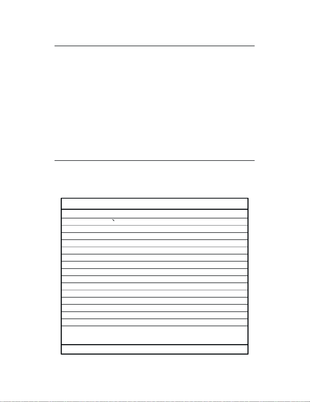
Channel Assignment
The NVFU memory has the capacity for 256-line forms. The first line identification code
(channel
identification
cation code. Filler channel codes are used for lines that will not be accessed by the print proĆ
gram. The same filler channel code can be repeated as necessary for any number of lines.
Table 5-7
code) in the memory load program defines the first line on the form; the second line
code defines the second line on the form, etc. Each line must have a line identifi
illustrates the channel codes and load sequence.
Ć
Setting
code being ignored until an end load code is received. The channel assignment code with bit 5
set
The
ly
be
hex)
bit 5 of a channel assignment code will result in all channel assignment codes after this
is accepted as the last line of the form.
top-of-form position is designated by channel
designated as
at the proper top-of-form position. After the memory is loaded, a F
will move the paper tothe next channel 1 (top-of-form).
a top-of-form. When the load sequence is received, the paper is assumed to
1. The first line of the form is automatical
orm F
eed code (FF
, 0C
End Load - 6F Hex
The
end load code terminates the memory load program. The end load code is 6F hex with the
PI
line high.
Table 5-7. NVFU Channel Codes
ASCII ChannelData Bits
Hex
60
61
62
63
64
65
66
67
68
69
6A
6B
6C
6E
6F
X = Undefined, 0 or 1 1 = High 0 = Low
Dec
96
97
98
99
100
101
102
103
104
105
106
107
108
110
111
Code
a
b
c
d
e
f
g
h
i
j
k
l
n
o
PI
0
0
0
0
0
0
0
0
0
0
0
0
0
1
1
0
76 5 4 3 21
8
0
1
X
X
X
X
X
X
X
X
X
X
X
X
X
X
X
X
1
1
100
1
1
1
1
1
1
1
1
1
1
1
1
1
1
1
1
1
1
1
1
1
1
1
1
1
1
1
1
0
0
0
0
0
0
0
0
0
1
0
0
1
0
0
1
0
0
1
0
0
0
1
0
0
1
0
0
1
0
0
1
0
1
1
0
1
1
0
1
1
0
X
X
N
1 (TOF)
0
0
2 (VT)
1
0
3
0
1
4
1
1
5
0
0
6
1
0
7
0
1
8
1
1
9
0
0
10
1
0
11
0
1
12
1
1
13
0
0
Start Load
0
1
End Load
1
1
LPI Byte
X
X
N=0=6 lpi
N=1=8 lpi
Ć
5-11Vertical Format Units
Page 92

Using the NVFU
The VFU LOADED indicator on the control panel lights when the NVFU program has been
enabled
the
number assigned in NVFU memory. For a data byte to be recognized as a NVFU channel inĆ
struction,
1.
2.
Given these conditions, the lower 4 bits of a byte will specify the NVFU channel number.
Table 5-8
and loaded. Sending an appropriate channel code to
buffer to print and slew the paper to the next line on the form having the specified channel
the following criteria must be met:
PI line must be enabled and set high; and
Data bit 5 must be 0 (not set).
lists NVFU channels and their equivalent data bytes.
the printer will cause any data in
Clearing the NVFU Memory
The
following actions will reset (clear) the NVFU memory.
1.
Only the start load code sent.
2.
Sending a start load code followed immediately by an end load code.
3. A second start load code is received, resulting in reinitialization of the NVFU. (This alĆ
the host data to be restarted.)
lows
When the NVFU memory is cleared, the forms length returns to the previously set value and
current print position becomes the top-of-form (TOF).
the
Table 5-8. NVFU Command Codes
ASCII NVFU Channel
Hex
Dec
00
01
02
03
04
05
06
07
08
09
0A
0B
0C
10
11
12
X = Undefined, 0 or 1 1 = High 0 = Low
Code
0
NUL
1
SOH
2
STX
3
ETX
4
EOT
5
ENQ
6
ACK
7
BEL
8
9
BS
HT
LF
VT
FF
PI 7 6 5 4 3 2 1
8
X
1
X
1
X
1
X
1
X
1
X
1
X
1
X
1
X
1
X
1
X
1
X
1
X
1
X
X
X
X
X
X
X
X
X
X
X
X
X
Data Bits
X
0
X
0
X
0
X
0
X
0
X
0
X
0
X
0
X
0
X
0
X
0
X
0
X
0
0
0
0
0
0
0
0
1
0
0
1
0
0
0
1
1
0
1
0
0
0
1
0
1
0
1
1
0
0
1
1
1
1
0
0
0
1
0
0
1
1
0
1
0
1
0
1
1
1
1
0
0
1 (TOF)
2
3
4
5
6
7
8
9
10
11
12
13
Vertical Format Units5-12
Page 93

Relative Line Slewing
Another
ber of lines within the form relative to the current print line (rather than slewing to a specific
line).
1.
2.
3.
The Slew Relative configuration and the status of data bits 7-6 and 1-4 determine the numĆ
ber
between line slewing and using the interface lines as NVFU channel codes.) As long as the
NVFU is selected, this type of vertical paper motion will occur regardless of whether the
NVFU
If
method of moving paper using the PI
F
or this to occur, three criteria must be met:
PI line must be set high;
Data bit 5 must be 1 (set); and
The NVFU must be the selected V
of lines slewed as described in T
memory is loaded or not.
the Double High for One Line attribute is active, n + 1 lines will be slewed rather than n lines.
Bits of Data Byte
1
1
XX0
n6 n5
able 5-9. (Note that the state of data bit 5 is the difference
Table 5-9.
0110n40n30n20
line results in vertical slews of a specified num
ertical F
ormat Unit.
NVFU Line Slewing
12345678PI Line
n1
Perform a CR function *
Slew 1 - 63 lines
Ć
CVFU
X = don't care (1 or 0)
n1 - n6 = decoded for 1 to 63 line movement
*treated as CR = CR; refer to the Carriage R
The
CVFU may be selected in P-Series protocol.
up to 126 lines, responding to Centronics Direct A
does not make use of the PI line for either loading or executing. The programming sequence is
1)
start load code; 2) line identification code; and 3) end load code.
eturn control code on page 6-16.
The CVFU provides 12 channels to identify
ccess F
ormat Unit
control codes. This VFU
Start Load Code - 1D Hex
The
start load code clears and initializes
start
load code is 1D hex. Subsequent data received after the start load code are interpreted
line
identification codes until the end load code is received.
the CVFU memory for the memory load program. The
as
Channel Assignment
Following the start load code, all data bytes received are interpreted as channel assignment
data
until the end load code is received.
5-13Vertical Format Units
Page 94
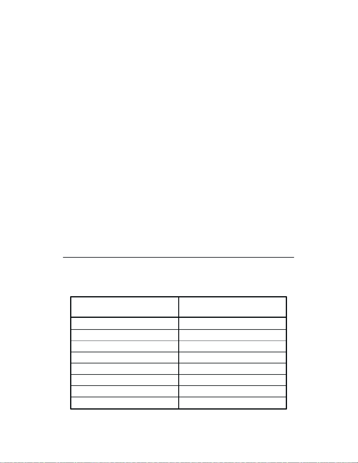
A
maximum of 12 channels can be assigned to one physical line on the form. T
bytes
(CVFU
bits of the first data byte are used to assign channels 1 through 6; the least significant 6 bits of
second data byte are used to assign channels 7 through 12. If a bit is set, the corresponding
the
channel
Each line on the form requires two bytes. For lines not requiring a channel identification, the
two
bytes should not contain channel assignments.
This procedure can be continued for a maximum of 126 lines (252 CVFU bytes). The CVFU
memory
CH 1 TOF - The first channel, line 1 of the form, must be assigned channel 1, top-of-form
Channel 2
and
sequence
hex) will move the paper tothe next channel 1 (top-of-form).
0C
After the channel assignment on the last line of the form, another channel assignment code
must be sent with the top-of-form bit set (called the dummy TOF"). This channel assignĆ
code does not count as a line of the form.
ment
ignored
as
part of the maximum allowed (126 lines, 252 bytes).
characters) are required per line. As shown in T
is assigned.
is cleared if more than 252 bytes are received before the end load code.
must not
is
ignored and the memory reset. After the memory is loaded, a F
until the end load code is received. Data received after the the dummy TOF is
be defined in this first byte (byte one, bit 2 must be 0) or the entire load
All data received after the dummy TOF will be
able 5-10, the least significant 6
wo eight-bit data
orm F
eed code (FF
counted
,
CH 2 VT
(0B
loaded,
is
ingle line feed occurs.
- Channel 2 is used as the vertical tab channel. After the memory is loaded, a VT code
hex) will move the paper to the next channel 2. If a VT code is received but channel 2 is not
the paper will advance to the next TOF position. If a VT code is received but the CVFU
not selected or not loaded, a s8
End Load Code - 1E Hex
The
CVFU end load code is 1E hex. This terminates the CVFU memory load routine.
Table 5-10. CVFU Channel Assignment
64
32
16
SECOND DATA BYTEFIRST DATA BYTE
Channel #Bit #
8
7
6
5
8
4
X (don't care)
12
11
10
Binary
Value
128
64
32
16
8
Bit #
8
7
6
5
4
Binary
Channel #
X (don't care)
set high (1) set high (1)
6
5
4
Value
128
4
2
1
3
2
1 (LSB)
3
2 - VT
1 - TOF
4
2
1
3
2
1 (LSB)
9
8
7
Vertical Format Units5-14
Page 95

Using the CVFU - 1F Hex
The VFU LOADED indicator on the control panel lights when the CVFU program has been
enabled
the
number assigned in CVFU memory. For a data byte to be recognized as a CVFU channel inĆ
struction,
1.
2.
Given these conditions, the lower 4 bits of a byte will specify the CVFU channel number.
Table 5-11
and loaded. Sending an appropriate channel code to
buffer to print and slew the paper to the next line on the form having the specified channel
the following criteria must be met:
A 1F hex code must have been received; and
Data bit 5 must be 0 (not set).
lists CVFU channels and their equivalent data bytes.
Table 5-11. CVFU Command Codes
the printer will cause any data in
ASCII CVFU Channel
Hex
X = Undefined, 0 or 1 1 = High 0 = Low
1F
01
02
03
04
05
06
07
08
09
0A
0B
0C
Dec
31 US
10
11
12
Code
1
SOH
2
STX
3
ETX
4
EOT
5
ENQ
6
ACK
7
BEL
8
9
BS
HT
LF
VT
FF
8
X
X
X
X
X
X
X
X
X
X
X
X
Data Bits
7654321
XX 1 1 1 1 1X Start Execute
X
X
0
0
0
0
1
X
X
0
0
0
1
0
X
X
0
0
0
1
1
X
X
0
0
1
0
0
X
X
0
0
1
0
1
X
X
0
0
1
1
0
X
X
0
0
1
1
1
X
X
0
1
0
0
0
X
X
0
1
0
0
1
X
X
0
1
0
1
0
X
X
0
1
0
1
1
X
X
0
1
1
0
0
Clearing the CVFU Memory
The
following actions will reset (clear) the CVFU memory.
1
2
3
4
5
6
7
8
9
10
11
12
1.
Only the start load and end load codes are sent (no channel data).
2. An odd number of CVFU characters (channel assignment data) are sent (detected after
end load code is received). R
the
3.
More than 126 lines (252 bytes) are sent without specifying the dummy TOF
4. The
first byte sent after the start load does not specify TOF or channel 2 is specified in the
first
byte.
emember, two data bytes are required per line.
.
5-15Vertical Format Units
Page 96

5.
Bit 7 is low during the CVFU load.
6. A second start load code is received, resulting in reinitialization of the NVFU. (This alĆ
the host data to be restarted.)
lows
When the CVFU memory is cleared, the forms length returns to the previously set value and
current print position becomes the top-of-form (TOF).
the
Relative Line Slewing
Another
ber of lines within the form relative to the current print line (rather than slewing to a specific
line).
1.
2.
3.
The
slewed as described in Table 5-12. (Note that the state of data bit 5 is the difference between
line slewing and using the interface lines as CVFU channel codes.) As long as the CVFU is
selected,
is
If
method of moving paper using the PI
F
or this to occur, three criteria must be met:
A 1F hex code must have been received;
Data bit 5 must be 1 (set); and
The CVFU must be the selected V
Slew R
loaded or not.
the Double High for One Line attribute is active, n + 1 lines will be slewed rather than n lines.
elative configuration and the status
this type of vertical paper motion will occur regardless of whether the CVFU memory
line results in vertical slews of a specified num
ertical F
ormat Unit.
of data bits 1-4 determine the number of lines
Ć
Vertical Format Units5-16
Page 97

Table 5-12. CVFU Line Slewing
ASCII Lines SlewedData Bits
Hex
10
11
12
13
14
15
16
17
18
19
1A
1B
1C
1D
1E
1F
X = Undefined, 0 or 1 1 = High 0 = Low
*treated as CR = CR; refer to the Carriage R
Dec
16
17
18
19
20
21
22
23
24
25
26
27
28
29
30
31
Code
DLE
DC1
DC2
DC3
DC4
NAK
SYN
ETB
CAN
EM
SUB
ESC
FS
GS
RS
US
76 5 4 3 21
8
0
0
000
0
0
000
0
0
000
0
0
000
0
0
000
0
0
000
0
0
000
0
0
000
0
0
1
0
0
1
0
0
0
1
0
0
1
0
1
0
1
1
0
1
0
1
0
1
1
0
1
0
0
1
1
0
1
1
0
0
1
1
0
1
1
0
1
1
1
1
1
1
0
1
1
1
1
1
1
0
eturn control code on page 6-16.
0
0
1
0
0
1
1
1
0
0
1
0
0
1
1
1
0
0
1
0
0
1
1
1
0
0
1
0
0
1
1
1
0 = CR*
1
2
3
4
5
6
7
8
9
10
11
12
13
14
15
Serial Matrix Vertical Formatting
In
Serial Matrix protocol, vertical formatting is always enabled. F
by
a set of programmed vertical tabs. V
are
then accessed by control code for rapid paper advancement to the tab position. T
are
used for controlling vertical
vertical
VFU Loaded indicator on the control panel will not light when vertical tabs are loaded for
forms
tab. These codes and their parameters are described in the P
control.
Executing Vertical Tabs
The
vertical tab execute code is VT
is in the buffer) and causes paper movement to the next predefined vertical tab position. If a
tab position is not defined, the paper is moved to the next line at the current line spacing. If a
position is at the current line, the paper is moved to the next tab position. If no tab positions
tab
are defined between the current line and the end of the form, the paper moves to the next topof-form
(TOF).
tabs: ESC B for single channel tab setting, and VT to execute a
. When sent, it prints the
arious lines of
orms
control is accomplished
the form are assigned vertical tabs which
wo codes
rogramming chapter. The
contents of the print buffer (if data
5-17Vertical Format Units
Page 98

Vertical Tab Positions
Vertical
be assigned on the form. A sample format is shown in Figure 5-1. The first vertical tab is asĆ
signed
tab is assigned line 14
lines of the form. Once the tab positions are assigned, sending the vertical tab execute code
(VT)
tion for PART NUMBER data. Sending another VT moves the paper to the second tab posiĆ
tion
data.
tab positions are assigned to a line number. A maximum of 16 vertical tab positions can
line 6 for part number data, a second tab is assigned line 8 for part
for
quantity data. The ESC B code is used to assign the vertical tabs to the
causes the paper (currently at the top-of-form position)
for PART NAME, followed by
Form Data
PART NUMBER
PART NAME
QUANTITY
a third VT to access the third tab position for QU
Form Line Number
1
2
3
4
5
6
7
8
9
10
11
12
13
14
15
to advance to the first tab posi
Vertical Tabs
Top of Form
Tab 1
Tab 2
Tab 3
name data, and a third
ANTITY
Ć
Figure 5-1.
20
Sample Serial Matrix V
ertical T
ab P
ositions
Vertical Format Units5-18
Page 99

Introduction
The
P9012 printer can be configured by from the control panel to respond to
ries or Serial Matrix control codes. This dual compatibility allows the programmer to choose
one of two standard protocols. If equipped with the Intelligent Graphics Processor (IGP) opĆ
tion,
the printer will respond to the Special F
described
in the IGP User's R
CHAPTER 6
PROGRAMMING
unction Control
eference Manual. This chapter describes:
Character and IGP commands as
Printronix P-SeĆ
n Overstrike/Overlay Mode n A
n
Control Code F
n
Special F
Code Header
unction Control
Overstrike/Overlay Mode
Data in the print buffer can be underlined or overstruck when the carriage return code (hex
0D) is configured for carriage return only (not carriage return and line feed). Any printable
characters in the data stream can overstrike printable characters or spaces already loaded in
the
print buffer as long as a paper motion command (ie: line feed, form feed) has not been re
ceived. The printer is in the Overstrike Mode when configured from the control panel for
OVERSTRIKE ENABLE. The Overstrike Mode causes the printer to double strike any dots
following
character
The printer is in the Overlay Mode when configured from the control panel with OVERĆ
STRIKE
top of existing data received before the carriage return. (No dots will be double struck.) The
Overlay
the
ple
the carriage return that lay on top of dots placed
bold, send the character, a carriage return, and the character again.
DIS
ABLE. The Overlay Mode causes dots following the carriage return to be laid on
Mode results in faster printing because it does not have to strike
Overlay Mode does not allow character bolding with the use of carriage returns. An exam
of overstrike/overlay and underlining characters is shown in Figure 6-1.
unctions n
ttribute Set and R
Control Code R
n
Individual Control Code Descriptions
eference Index
before
the carriage return. T
eset Codes
dots twice; however,
Ć
o make a
Ć
Enter in Print Buffer Printed Result
P9000 SERIES PRINTER (CR)
SS/// (CR)
_____ (LF)
S = Space (20 Hex)
LF = Line Feed (0A Hex)
* NOTE: The printer must be configured for CR=CR only. If configured for a carriage return
plus
line feed on receipt of the CR code, the contents of the buffer will be printed.
Figure 6-1. Overstrike/Overlay and Underline Examples
CR = Carriage Return (0D Hex)*
_ = Underline (5F Hex)
P9000 SERIES PRINTER///
6-1Programming
Page 100

Control Code Functions
The
following information is listed for each code function (where applicable and possible).
ASCII Mnemonic
Hex Code
Decimal Code
P
urpose
Comment
A sample Expression written in BASIC programming language is provided for some control
codes when a specific syntax is required to complete the program statement (ie: Bit Image
modes, Download a Language, Download a Character, Horizontal Tab Set, Vertical Tab Set/
Clear).
GW-BASIC
- The code's numeric equivalent in hexadecimal.
- The function(s) of the control code.
- A description of exceptions or limitations to normal use.
The programs in this chapter were run on an IBM P
- The standard A
- The code's numeric equivalent in decimal.
version 3.22.
SCII name for the control code.
ersonal
Computer using Microsoft
Special Function Control Code - Control Code Header
A Special Function Control Code (SFCC) is used to extend the control code protocol. The
is the control code introducer (or header); it is the
SFCC
ters.
The general control code sequence is:
(SFCC)(parameter 1)(parameter 2)...(parameter n)
P-Series codes can use SOH, ETX, ESC, ^ (hat") or ~ (tilde") as control code introĆ
ducers. For example, bold print can be enabled in the P-Series protocol using any of the folĆ
lowing
control code introducers:
first input in the sequence of parame
Ć
ASCII: Hex: BASIC:
ETX G
ESC G
^ G
~ G
Serial Matrix codes
print in the Serial Matrix printer protocol, use
trol
code character G as follows:
ASCII: Hex: BASIC:
SFCC is selected from the control panel. T
The
the Application Compatibility diagrams in the Configuration
amples
in this chapter have been created using the ESC control code introducer.)
NOTE:
by text following the command string. A paper motion command
cial
SFCC commands must be terminated by a semicolon (;) in a BASIC program or
function code command may result in erroneous paper movement.
use only
ESC as the control code introducer. For example, to enable bold
01 47SOH G
03 47
27 47
5E 47
7E 47
1B 47ESC G
the Serial Matrix SFCC and the bold print con
o select
the SFCC for your application, refer to
chapter.
CHR$(1);“G”;
CHR$(3);“G”;
CHR$(27);“G”;
CHR$(94);“G”;
CHR$(126);“G”;
CHR$(27);“G”;
(Most programming ex
directly
following a spe
Ć
Ć
Ć
Programming6-2
 Loading...