

Page 1
P8000 Series Cartridge Ribbon Printer
User’s Manual
Page 2

READ THIS SOFTWARE LICENSE AGREEMENT BEFORE USING THIS PRINTER
Software License Agreeme nt
CAREFULLY READ THE FOLLOWING TERMS AND
CONDITIONS BEFORE USING THIS PRINTER. USING THIS
PRINTER INDICATES YOUR ACCEPTANCE OF THESE
TERMS AND CONDITIONS. IF YOU DO NOT AGREE TO
THESE TERMS AND CONDITIONS, PROMPTLY RETURN
THE PRINTER AND ALL ACCOMPANYING HARDWARE
AND WRITTEN MATERIALS TO THE PLACE YOU
OBTAINED THEM, AND YOUR MONEY WILL BE
REFUNDED.
Definitions.
“Software” shall mean the digitally encoded, machine-readable
data and program. The term “Software Product” includes the
Software resident in the printer and its documentation. The
Software Product is licensed (not sold) to you, and Printronix,
Inc. either owns or licenses from other vendors who own, all
copyright, trade secret, patent and other proprietary rights in
the Software Product.
License.
1.
Authorized Use. You agree to accept a non-exclusive
license to use the Software resident in the printer solely
for your own customary business or personal purposes.
2.
Restrictions.
a. To protect the proprietary rights of Printronix, Inc.,
you agree to maintain the Software Product and
other proprietary information concerning the
typefaces in strict confidence.
b. You agree not to duplicate or copy the Software
Product.
c. You shall not sublicense, sell, lease, or otherwise
transfer all or any portion of the Software Product
separate from the printer, without the prior written
consent of Printronix, Inc.
d. You may not modify or prepare derivative works of
the Software Product.
e. You may not transmit the Software Product over a
network, by telephone, or electronically using any
means; or reverse engineer, decompile or
disassemble the Software.
f. You agree to keep confidential and use your best
efforts to prevent and protect the contents of the
Software Product from unauthorized disclosure or
use.
3.
Transfer. You may transfer the Software Product with the
printer, but only if the recipient agrees to accept the
terms and conditions of this Agreement. Your license is
automatically terminated if you transfer the Software
Product and printer.
Limited Software Product Warranty
Printronix, Inc. warrants that for ninety (90) days after delivery,
the Software will perform in accordance with specifications
published by Printronix, Inc. Printronix, Inc. does not warrant
that the Software is free from all bugs, errors and omissions.
Remedy
Your exclusive remedy and the sole liability of Printronix, Inc.
in connection with the Software is replacement of defective
software with a copy of the same version and revision level.
Disclaimer of Warranties and Limitation of Remedies
1.
THE PARTIES AGREE THAT ALL OTHER
WARRANTIES, EXPRESS OR IMPLIED, INCLUDING
WARRANTIES OF FITNESS FOR A PARTICULAR
PURPOSE AND MERCHANTABILITY ARE EXCLUDED.
Printronix, Inc. does not warrant that the functions
contained in the Software will meet your requirements or
that the operation of the Software will be uninterrupted or
error free. Printronix, Inc. reserves the right to make
changes and/or improvements in the Software without
notice at any time.
2.
IN NO EVENT WILL PRINTRONIX, INC. BE LIABLE
FOR LOST PROFITS, LOST DATA, BUSINESS
INTERRUPTIONS, OR ANY OTHER DIRECT,
INDIRECT, INCIDENTAL OR CONSEQUENTIAL
DAMAGES ARISING OUT OF THE USE OF OR
INABILITY TO USE THIS PRODUCT, EVEN IF
PRINTRONIX, INC. HAS BEEN ADVISED OF THE
POSSIBILITY OF SUCH DAMAGES, OR ANY
DAMAGES CAUSED BY THE ABUSE OR
MANIPULATION OF THE SOFTWARE. SOME STATES
DO NOT ALLOW THE EXCLUSION OR LIMITATION OF
LIABILITY FOR CONSEQUENTIAL OR INCIDENTAL
DAMAGES, SO THE ABOVE LIMITATION MAY NOT
APPLY TO YOU.
3.
Printronix, Inc. will not be liable for any loss or damage
caused by delay in furnishing a Software Product or any
other performance under this Agreement.
4.
Our entire liability and your exclusive remedies for our
liability of any kind (including liability for negligence
except liability for personal injury caused solely by our
negligence) for the Software Product covered by this
Agreement and all other performance or nonperformance
by us under or related to this Agreement are limited to the
remedies specified by this Agreement.
5.
California law governs this Agreement.
Termination of License Ag reement
This License shall continue until terminated. This license may
be terminated by agreement between you and Printronix, Inc.
or by Printronix, Inc. If you fail to comply with the terms of this
License and such failure is not corrected within thirty (30) days
after notice. When this License is terminated, you shall return
to the place you obtained them, the printer and all copies of the
Software and documentation.
U.S. Government Rest ri cted Rights
Use, duplication or disclosure by the Government is subject to
restrictions as set forth in the Rights in Technical Data and
Computer Software clause at FAR 242.227-7013, subdivision
(b) (3) (ii) or subparagraph (c) (1) (ii), as appropriate. Further
use, duplication or disclosure is subject to restrictions
applicable to restricted rights software as set forth in FAR
52.227-19 (c) (2).
Acknowledgement of Terms and Conditions
YOU ACKNOWLEDGE THAT YOU HAVE READ THIS
AGREEMENT, UNDERSTAND IT, AND AGREE TO BE
BOUND BY ITS TERMS AND CONDITIONS. NEITHER
PARTY SHALL BE BOUND BY ANY STATEMENT OR
REPRESENTATION NOT CONTAINED IN THIS
AGREEMENT. NO CHANGE IN THIS AGREEMENT IS
EFFECTIVE UNLESS WRITTEN AND SIGNED BY
PROPERLY AUTHORIZED REPRESENTATIVES OF EACH
PARTY. BY USING THIS PRINTER, YOU AGREE TO
ACCEPT THE TERMS AND CONDITIONS OF THIS
AGREEMENT.
Page 3

User’s Manual
P8000 Series Cartridge Ribbon Printers
Page 4

This document contains proprietary information protected by copyright. No
part of this document may be reproduced, copied, translated, or incorporated
in any other material in any form or by any means, whether manual, graphic,
electronic, mechanical, or otherwise, without the prior written consent of
Printronix.
Printronix makes no representations or warranties of any kind regarding this
material, including, but not limited to, implied warranties of merchantability
and fitness for a particular purpose. Printronix shall not be held responsible
for errors contained herein or any omissions from this material or for any
damages, whether direct or indirect, incidental or consequential, in connection
with the furnishing, distribution, performance, or use of this material. The
information in this manual is subject to change without notice.
COPYRIGHT 2013 PRINTRONIX, INC.
T r ademark A cknowle dgements
ANSI is a registered trademark of the American National Standards Institute,
Inc.
Artifex, the Artifex logo , Ghostscript, and the Ghostscript logo
are registered trademarks of Artifex Software, Inc.
PostScript is a trademark of Adobe Systems Incorporated.
Centronics is a registered trademark of Genicom Corporation.
CSA is a registered certification mark of the Canadian Standards Association.
Dataproducts is a registered trademark of Dataproducts Corporation.
EIA is a registered service mark of the Electronic Industries Association.
ENERGY STAR is a registered trademark of the United States Environmental
Protection Agency. As an ENERGY STAR
determined that this product meets the ENERGY STAR guidelines for energy
efficiency.
Epson is a registered trademark of Seiko Epson Corporation.
Ethernet is a trademark of Xerox Corporation.
IBM, AS/400, and Proprinter are registered trademarks, and Intelligent Printer
Data Stream and IPDS are trademarks of International Business Machines
Corporation.
IEEE is a registered service mark of the Institute of Electrical and Electronics
Engineers, Inc.
Printronix, PGL, LinePrinter Plus, and IGP are registered trademarks, and
P8005, P8010, P8015, P8205, P8210, P8215, P8220, and SureStak are
trademarks of Printronix, Inc.
QMS is a registered trademark, and Code V is a trademark of Quality Micro
Systems, Inc.
TUV is a registered certification mark of TUV Rheinland of North America, Inc.
UL is a registered certification mark of Underwriters Laboratories, Inc.
®
Partner, Printronix has
Page 5

Table of Contents
1 Introduction........................................................... 11
Printer Overview .....................................................................................11
Printronix P8000 Series Cartridge Ribbon Printers (CRP) ...............11
Consumable Monitoring with PrintNet Enterprise ...................................14
Protocols and Emulations.......................................................................15
Graphics Enhancements ........................................................................15
Taking Care of Your Printer....................................................................15
Conventions in this Manual.....................................................................15
Warnings and Special Information..........................................................16
Related Documents ................................................................................16
Contact Information ................................................................................17
Printronix Customer Support Center ................................................ 17
Printronix Supplies Department........................................................ 17
Corporate Offices .............................................................................18
2 Setting Up The Printer .......................................... 19
Before You Begin....................................................................................19
Power Requirements ..............................................................................19
Select a Site............................................................................................19
Printer Dimensions .................................................................................21
Printer Component Locations .................................................................26
3 Operating The Printer ........................................... 27
Powering on the Printer ..........................................................................27
Operating Modes ....................................................................................27
The Control Panel...................................................................................28
Control Panel Keys ..........................................................................29
Cancel a Print Job ............................................................................33
Operational Procedures..........................................................................34
Reload Paper ................................................................................... 34
Unload Paper ................................................................................... 45
Integrated Print Management System ....................................................48
Output Darkness ..............................................................................48
Loading a Used Ribbon Cartridge.................................................... 49
Lighter or Darker Print ...................................................................... 49
Changing Ribbon Cartridge..............................................................50
Page 6

Table of Contents
4 The Configuration Menus .....................................53
Configuration Overview ..........................................................................53
Main Menu .......................................................................................53
Changing Parameter Settings ..........................................................54
Saving Parameter Settings ..............................................................54
Default and Custom Configurations ................................................. 54
Navigating the Menus ......................................................................55
Top Level Menu Overview ...................................................................... 56
Changing Parameters Example ....................................................... 58
Auto Save Configuration .................................................................. 62
Saving Your New Configuration ....................................................... 63
Optimizing Print Quality....................................................................68
Optimizing Print Speed ....................................................................69
Dynamic Menu Options ..........................................................................70
Active Emulations ................................................................................... 71
P8000 Standard Firmware ...............................................................73
P8000 TN Firmware .........................................................................74
P8000 PCL-II Firmware....................................................................75
P8000 LG Firmware .........................................................................76
P8000 ANSI Firmware .....................................................................77
OpenPrint P8000 Standard Postscript/PDF Firmware ..................... 78
OpenPrint P8000 HD Postscript/PDF Firmware ..............................79
H-Series Firmware.................................................................................. 80
P8000 Indian Language Firmware.......................................................... 81
QUICK SETUP Menu ............................................................................. 82
CONFIG. CONTROL Menu ....................................................................91
HOST INTERFACE Menu ...................................................................... 93
Auto Switching Submenu ................................................................. 94
IEEE 1284 Parallel (Bidirectional) Submenu....................................96
Centronics (Parallel) Submenu ........................................................ 98
Serial Submenu..............................................................................100
NETWORK SETUP Menu .................................................................... 105
Ethernet Address ........................................................................... 105
Ethernet Params ............................................................................ 107
ACTIVE IGP EMUL and ACTIVE EMULATIONS .................................109
EMULATION Menu...............................................................................111
3270 Params.................................................................................. 112
5250 Params.................................................................................. 119
LinePrinter Plus Emulation (ASCII, Indian Language) ...................124
LinePrinter Plus Emulation (H-Series Hanzi GB) ........................... 126
LinePrinter Plus Emulation (H-Series Kanji) .................................. 128
LinePrinter Plus Emulation (H-Series Hangul) ...............................132
Page 7

Table of Contents
P-Series Emulation ........................................................................147
P-Series XQ Emulation .................................................................. 153
Serial Matrix Emulation ..................................................................155
Proprinter XL Emulation ................................................................. 160
Epson FX Emulation ......................................................................163
ANSI Emulation .............................................................................. 166
IGP/PGL Emulation ........................................................................ 173
IGP/PGL Submenu ........................................................................175
IGP/VGL Emulation ........................................................................ 185
IGP/VGL Submenu ........................................................................186
IPDS Emulation .............................................................................. 197
PCL - II Emulation ..........................................................................202
LG Emulation .................................................................................206
OpenPrint POSTSCRIPT/PDF Emulation...................................... 211
Postscript/PDF Interpreter..............................................................211
PRINTER CONTROL Menu .................................................................216
ADVANCED USER Menu..................................................................... 220
SURE SCAN Submenu .................................................................. 222
DIAGNOSTICS Menu ...........................................................................238
Printer Mgmt Menu ...............................................................................242
5 Interfaces............................................................ 243
Overview...............................................................................................243
RS-232 Serial Interface ........................................................................245
USB ......................................................................................................246
Centronics Parallel Interface.................................................................247
Centronics Parallel Interface Signals ............................................. 248
IEEE 1284 Parallel Interface.................................................................249
Compatibility Mode.........................................................................249
Nibble Mode ...................................................................................249
Byte Mode ......................................................................................249
Signals ........................................................................................... 250
Ethernet ................................................................................................252
6 Reprogramming the Security Key....................... 253
Reprogramming the Security Key......................................................... 253
How to Program the Security Key .................................................. 253
Page 8

Table of Contents
7 Downloading Firmware ....................................... 255
Firmware File Types (.prg) and (.exe) .................................................. 256
Web Page Download ............................................................................257
Windows Driver Download.................................................................... 259
Automatic Download (.exe)...................................................................260
Manual Two-Key Download Sequence................................................. 262
Manual Three-Key Download Sequence ..............................................263
Sending Firmware in Download Mode.................................................. 264
Sending Firmware via Ethernet (LPR) ...........................................264
Sending Firmware via USB ............................................................ 264
Installing a Microsoft Loopback Adapter ........................................ 265
Sending Firmware via Parallel .......................................................270
Sending Firmware via Serial ..........................................................271
Downloading Files to the Main File System.......................................... 272
Filename Extensions Not Shown in Menus ..........................................272
File Properties Not Shown in Menus ....................................................273
Web Page Download ............................................................................273
PTX_SETUP Download........................................................................275
Manual Two-Key Download..................................................................275
Downloading Files to the SD Card........................................................ 276
Using TrueType Fonts ..........................................................................277
Downloading TrueType Fonts ........................................................ 277
Select and Print Downloaded TrueType Fonts .............................. 279
Demo Facility ........................................................................................280
8 Troubleshooting ..................................................283
Cleaning Requirements ........................................................................283
Exterior Cleaning............................................................................283
Interior Cleaning ............................................................................. 284
Diagnosing Problems............................................................................ 286
Bar Code Verification .....................................................................286
Printing a Hex Dump ......................................................................287
Most Frequent Problems and Solutions................................................289
Diagnostics for EXX, BAD NVM, or ILL NVM Errors ............................290
Fault Messages (ASCII in Alphabetical Order) ..................................... 290
Fault Messages (H-Series with Numerical Prefix) ................................310
Page 9

Table of Contents
A Printer Specifications ......................................... 327
Ribbon Cartridge Specifications ...........................................................327
ASCII..............................................................................................327
HD and H-Series ............................................................................327
Paper Specifications .............................................................................328
Labels ...................................................................................................328
Printer Weight and Dimensions ............................................................329
Environmental Characteristics..............................................................329
Acoustic Noise Level ............................................................................330
Energy Star........................................................................................... 330
Electrical Characteristics ......................................................................331
Input Voltage (ASCII Models).........................................................331
Input Voltage (H-Series Models) ....................................................332
Interfaces ..............................................................................................332
Printing Speed ......................................................................................333
B ASCII Character Set........................................... 335
C SureStak™ Power Stacker ................................ 337
Introduction ...........................................................................................337
Stacker Operation................................................................................. 337
D Zero Tear Pedestal Printer................................. 343
Overview...............................................................................................343
Operation ..............................................................................................344
Position the Paper Input and Adjust the Paper Guides..................344
Load Paper.....................................................................................346
Position the Paper Out Sensor.......................................................348
Set the Tear Bar Distance .............................................................. 349
Set the Top of Form ....................................................................... 350
ZTP SETTINGS Menu ..........................................................................351
Performance Limitations .......................................................................352
E Quick Change Memory Cartridge (QCMC) ........ 355
Overview...............................................................................................355
Installing the QCMC.............................................................................. 356
Saving the Printer’s Configuration to the QCMC ..................................357
Copying the QCMC “Snapshot” Image to a Second Printer .................359
Page 10

Table of Contents
F PTX_SETUP Commands ...................................361
Overview...............................................................................................361
The PTX_SETUP Commands ..............................................................361
General Commands .......................................................................362
Line Matrix Commands .................................................................. 369
G Customer Support..............................................371
Printronix Customer Support Center..................................................... 371
Printronix Supplies Department ............................................................371
Corporate Offices.................................................................................. 372
H Communication Notices ..................................... 373
Notices.................................................................................................. 373
Energy Star........................................................................................... 375
Communication Statements.................................................................. 376
Software License Agreement................................................................ 381
Page 11

1
Printer Overview
This chapter provides a general overview of your printer and the conventions
used within this manual.
Printronix P8000 Series Cartridge Ribbon Printers (CRP)
Printronix® has been the global leader in industrial printing solutions for over
30 years, earning a reputation for designing and manufacturing leading edge
products and delivering them to market with unsurpassed service and
support.
The Printronix P8000™ Line Matrix Printing Platform extends the series of
technology innovations that cement Printronix’s leadership position. Line
matrix printing is Printronix’s flagship technology, and it remains the
workhorse solution for supply-chain and back-office printing applications
because of its reliability, lower cost of ownership and flexibility of printing
applications.
Introduction
•
Most reliable printer ever – provides more up time and lower operating
costs
•
Cartridge ribbons – deliver darker image, last longer, and costs less to
operate than other print technologies
•
Integrated print management system – provides precise control over print
quality, print costs, and job planning
•
Tabletop, cabinet, pedestal, enclosed pedestal, or zero tear pedestal
(ZTP) styles – best user access and forms handling flexibility
•
Unsurpassed ease of use – larger graphics LCD simplifies operation and
enhances productivity
11
Page 12
Chapter 1
Printer Overview
Table 1. P8000 Series Models and Configurations
Model Number Configuration
LMPPLS
(Line Matrix Printer Pedestal Low Speed)
LMPPHS
(Line Matrix Printer Pedestal High Speed)
LMPCLS
(Line Matrix Printer Cabinet Low Speed)
Print Speed
(Lines per Minute)
P8003H 300
P8003HZT 300
P8005 500
P8005ZT 500
P8010 1000
P8010ZT 1000
P8006 600
P8006HZT 600
P8000HD 600
P8000HDZT 600
P8203H 300
P8205 500
P8210 1000
P8215 1500
LMPCHS
(Line Matrix Printer Cabinet High Speed)
P8220 2000
P8215 (with stacker) 1500
P8220 (with stacker) 2000
P8206H 600
P8208H 800
P8200HD 800
12
Page 13

Printronix P8000 Series Cartridge Ribbon Printers (CRP)
Five printer configurations are available:
T abletop (P80XX or P80XXH)
•
The tabletop models are designed for space constrained environments,
allowing for the printer to be placed on a desk or tabletop for quiet use.
•
Paper guides allow for paper input under the table or as a small stack on
the table.
•
Output forms are easily accessible from the front of the printer.
•
Using the top paper exit, this printer is ideal for short print runs and easy
access to output.
•
Available in the following print speeds:
ASCII – 500 and 1000 line per minute models
H-Series – 300 and 600 line per minute models
Cabinet (P82XX, P8200HD, or P82XXH)
•
The enclosed cabinet models provide for near silent operation, making
these printers perfectly suitable for use in the quietest of office
environments.
•
Provides the best paper handling for large print runs. All paper input and
output is contained inside the cabinet and protected from bumping and
contamination.
•
Highly effective combination of moveable fences and chains allows for
precise stacking all the way up to a full box of paper.
•
For tougher forms that tend not to refold well, a SureStak power stacker
option is available for the 1500, 2000, H-Series, and OpenPrint HD
enclosed cabinet models.
•
Available in the following print speeds:
ASCII – 500, 1000, 1500 and 2000 line per minute models
H-Series – 600 and 800 line per minute models
OpenPrint HD (available only for cabinet models)
Pedestal (P80XX, P8000HD, or P80XXH)
•
The pedestal model has a clamshell design that allows easy access to all
controls providing faster ribbon replacements and easier paper loading.
•
Oversized casters are standard making movement easy.
•
Available in the following print speeds:
ASCII – 500 and 1000 line per minute models
H-Series – 300 and 600 line per minute models
13
Page 14

Chapter 1
Consumable Monitoring with PrintNet Enterprise
Enclosed Pedestal (P80XX or P80XXH )
•
The enclosed pedestal model has a lower enclosure that holds the input
paper while providing for near silent operation.
•
The paper enclosure can accommodate a full paper box (12” maximum
length forms).
•
The paper output area is not enclosed for easy access to printed media.
•
Available in the following print speeds:
ASCII – 500 and 1000 line per minute models
H-Series – 300 and 600 line per minute models
Zero Tear Pedest al (P80XXZ T or P80XXHZ T)
•
Special push tractor configuration enables printing from the very first to
the very last line of a form and then tear-off with no forms lost
•
The elimination of wasted forms between jobs can yield significant
savings.
•
An ideal solution for supply-chain and back-office applications.
•
Available in the following print speeds:
ASCII – 500 and 1000 line per minute models
H-Series – 300 and 600 line per minute models
Consumable Monitoring with PrintNet Enterprise
The Integrated Print Management System works with PrintNet Enterprise
(PNE). PNE allows a system administrator to remotely view the current
consumable status of all printers. PNE can be configured to deliver alerts on
all consumable warnings. When a ribbon reaches the low state, PNE notifies
the system administrator remotely via an automated e-mail alert of the low
condition. This allows corrective action to be taken before the ribbon reaches
its end of life. If the ribbon is not changed, an alert will again be initiated once
the ribbon reaches the 0% end point. Refer to your PrintNet Enterprise
Remote Management Software manual for details.
14
Page 15

Printronix P8000 Series Cartridge Ribbon Printers (CRP)
Protocols and Emulations
A protocol is a set of rules governing the exchange of information between the
printer and its host computer. These rules consist of codes that manipulate
and print data and allow for machine-to-machine communication. A printer
and its host computer must use the same protocol. As used in this manual,
protocol and emulation mean the same thing.
Most impact printers use single ASCII character codes to print text, numbers,
and punctuation marks. Some characters are defined as control codes.
Control codes instruct the printer to perform specific functions, such as
underlining text, printing subscripts, setting page margins, etc. The difference
between most printer protocols is the characters used to create control codes
and the ways in which these characters are formatted.
When the printer executes the character and control codes of a particular
printer protocol, it is emulating that printer.
Graphics Enhancement s
The IGP/PGL and IGP/VGL emulations allow you to create and store forms,
generate logos, bar codes, expanded characters, and create other graphics.
Alphanumeric and bar code data are added as the form is printed.
These emulations are available as factory-installed or field-installed options,
except on H-series models. For more information, contact your authorized
service representative.
Taking Care of Your Printer
Your printer will produce high print quality jobs if it is well taken care of.
Periodic cleaning, handling the printer properly, and using the correct printer
supplies such as ribbon and paper ensures optimum performance. Chapter 8
explains how to clean the printer, and printer supplies are listed in
Appendix A.
Conventions in this Manual
Control panel keys and indicators are highlighted in UPPERCASE BOLD
PRINT.
Example: Press the CANCEL key, then press the ONLINE key.
Quotation marks (“ ”) indicate messages on the Liquid Crystal Display (LCD).
Example: Press the ONLINE key. “OFFLINE” appears on the LCD.
The + (plus) symbol represents key combinations.
Example: “Press + ” means press the (UP) key and the (DOWN)
key at the same time.
15
Page 16

Chapter 1
Warnings and Special Information
W arnings and Special Information
Read and comply with all information highlighted under special headings:
WARNING
CAUTION
IMPORTANT
A warning notice calls attention to a condition that could harm you.
A caution notice calls attention to a condition that could damage the
printer.
Information vital to proper operation of the printer.
NOTE: A note gives you helpful tips about printer operation and
maintenance.
Related Documents
•
Quick Reference Guide — Explains how to set up the printer for basic
operation (load ribbon cartridge and media, and clear paper jams).
•
Maintenance Manual — Explains how to maintain and repair the line
matrix printer at the field service level of maintenance.
•
ANSI Programmer's Reference Manual — Provides host control codes
and character sets for the ANSI emulation.
•
PCL®-II/LinePrinter Plus Programmer’s Reference Manual — Provides
host control codes and character sets for the PCL-II emulation.
•
LG Programmer’s Reference Manual — Provides host control codes and
character sets for the LG emulation.
•
Character Sets Reference Manual — Information about and examples of
the character sets available in line matrix printers.
•
IGP/PGL Programmer's Reference Manual — Provides information used
with the optional IGP Printronix emulation enhancement feature.
•
IGP/VGL Programmer's Reference Manual — Provides information used
with the optional Code V
•
PrintNet Ethernet User's Manual — Information about network protocols,
configuration, and operation.
•
IPDS Emulation Programmer's Reference Manual — Provides an
overview of Intelligent Printer Data Stream
and diagnostics.
•
LinePrinter Plus Programmer's Reference Manual — Covers the host
control codes for the LinePrinter Plus emulation.
•
LQ-1600K Emulation For The P8000 H-Series Of Line Matrix Printers
Programmer’s Reference Manual — Covers the host control codes for the
LQ-1600K emulation.
•
KS Programmer’s Reference Manual — Covers the host control codes for
the KS emulation.
•
KSSM Programmer’s Reference Manual — Covers the host control codes
for the KSSM emulation.
TM
emulation enhancement feature.
TM
(IPDS) features, commands,
16
Page 17

Contact Info rmation
Printronix Customer Support Ce nter
Printronix Customer Support Center
IMPORTANT
Please have the following information available prior to calling the
Printronix Customer Support Center:
•
Model number
•
Serial number (located on the back of the printer)
•
Installed options (i.e., interface and host type if applicable to the problem)
•
Configuration printout (Press CONFIG on the control panel, then press
ENTER)
•
Network test page if Ethernet is enabled.
•
Is the problem with a new install or an existing printer?
•
Description of the problem (be specific)
•
Good and bad samples that clearly show the problem (faxing or emailing
of these samples may be required)
Americas (714) 368-2686
Europe, Middle East, and Africa (31) 24 6489 311
Asia Pacific (65) 6548 4114
China (86) 800-999-6836
http://www.printronix.com/support.aspx
Printronix Supplies Dep artment
Contact the Printronix Supplies Department for genuine Printronix supplies.
Americas (800) 733-1900
Europe, Middle East, and Africa (33) 1 46 25 19 07
Asia Pacific (65) 6548 4116
or (65) 6548 4132
China (86) 400-886-5598
India (800) 102-7869
http://www.printronix.com/public/supplies/default.aspx
17
Page 18

Chapter 1
Contact Information
Corporate Offices
Printronix, Inc.
15345 Barranca Parkway
Irvine, CA 92618
U.S.A.
Phone: (714) 368-2300
Fax: (714) 368-2600
Printronix Inc.
c/o Printronix Nederland BV
Bijsterhuizen 11-38
6546 AS Nijmegen
The Netherlands
Phone: (31) 24 6489489
Fax: (31) 24 6489499
Printronix Schweiz GmbH
42 Changi South Street 1
Changi South Industrial Estate
Singapore 486763
Phone: (65) 6542 0110
Fax: (65) 6546 1588
Printronix Commercial (Shanghai) Co. Ltd
22F, Eton Building East
No.555, Pudong Av.
Shanghai City, 200120, P R China
Phone: (86) 400 886 5598
Fax: (86-21) 5138 0564
Visit the Printronix web site at www.printronix.com
18
Page 19

2
Setting Up The Printer
Before You Begin
Read this chapter carefully before installing and operating the printer. The
printer is easy to install. However, for your safety and to protect valuable
equipment, perform all the procedures in this chapter in the order presented.
Power Requirements
The printer must be connected to a power supply outlet that supplies 90 to
264 volts AC at its upper and lower limits. These limits take into account
normal voltage sags and surges created on the nominal line voltage by other
AC power loads associated with the AC distribution line. The printer
automatically senses and adjusts itself to conform to the correct voltage
range.
Primary circuit protection is provided by the AC source protection device.
Consult an electrician if printer operation affects local electrical lines.
IMPORTANT
Select a Site
Printer power should be supplied from a separate AC circuit protected
at 20 amperes maximum for 100 - 240 volts at 50 or 60 Hertz.
Select a printer site that meets all of the following requirements:
•
Permits complete opening of the printer cover and doors.
•
For cabinet models, allows at least three feet of clearance behind the
printer. (This permits air to circulate freely around the printer and provides
access to the paper stacking area.)
•
For pedestal models, DO NOT place the side of the printer (inlet and exit
air vents) against a wall or other object. A minimum of 6 inch spacing is
recommended.
•
Has a standard power outlet that supplies 100-135 Volts AC or
178-240 Volts AC power, at 47 to 63 Hz.
•
Is relatively dust-free.
•
Has a temperature range of 10° C to 40° C (50° F to 104° F) and a
relative humidity from 15% to 90% non-condensing.
19
Page 20
Chapter 2
Select a Site
•
Is located within the maximum allowable cable length to the host
computer. This distance depends on the type of interface you plan to use,
as shown in Table 2.
T a ble 2. Maximum Interface Connection Cable Length
Interface Type Maximum Cable Length
Centronics Parallel 5 meters (15 feet)
IEEE 1284 Parallel 10 meters (32 feet)
Serial RS-232 15 meters (50 feet)
USB 2.0 Universal Serial Bus 5 meters (15 feet)
Twisted Pair / Type 3 300 meters (985 feet)
Ethernet 10/100Base-T 100 meters (328 feet)
20
Page 21
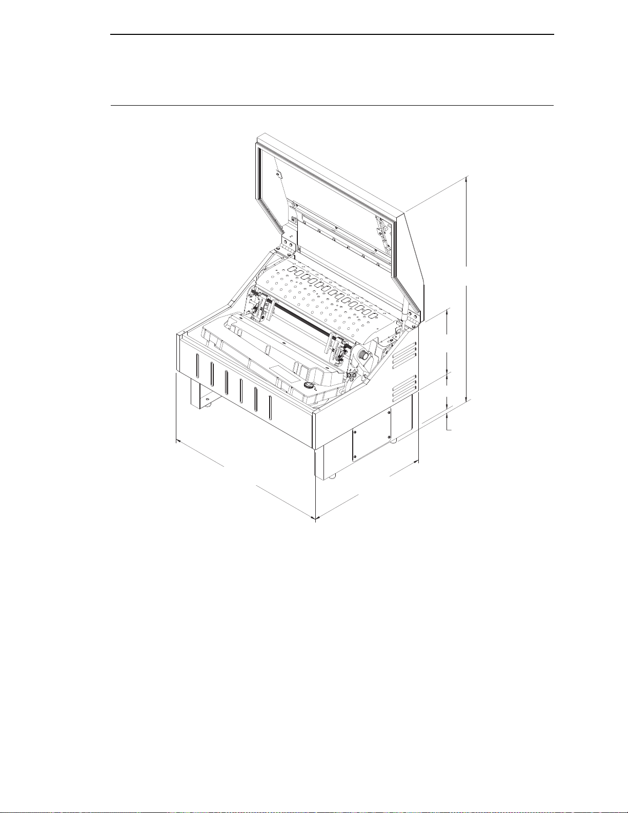
Printer Dimensions
184751c
37.73 in
(95.8 cm)
11.36 in
(28.9 cm)
6.1 in
(15.5 cm)
19.1 in
(73.9 cm)
25.92 in
(65.8 cm)
.75 in
(1.9 cm)
Figure 1. Tabletop Model
21
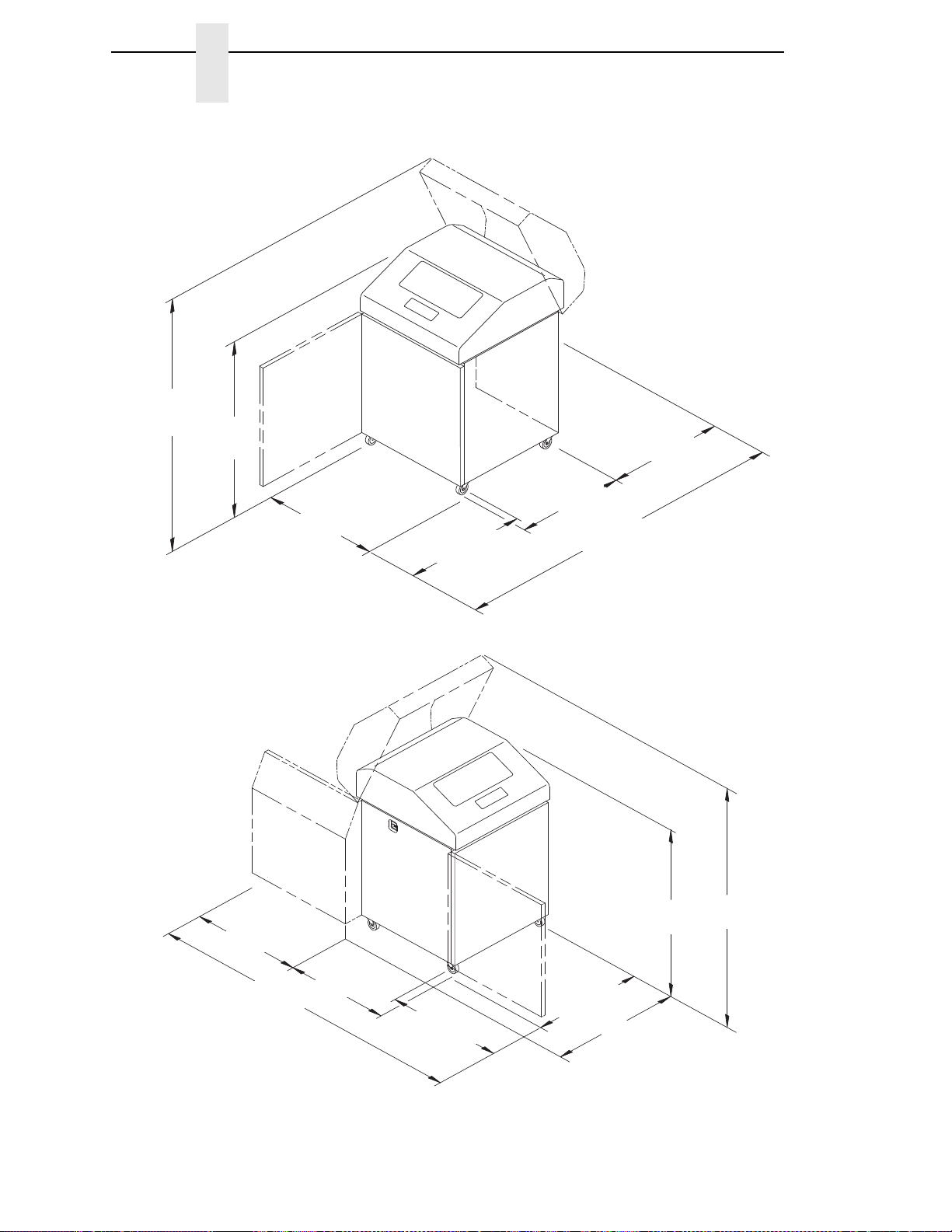
Page 22
Chapter 2
184819a
83.0 in
(210.8 cm)
29.0 in
(73.7 cm)
27.0 in
(68.6 cm)
27.0 in
(68.6 cm)
27.0 in
(68.6 cm)
57.5 in
(146.1 cm)
41.0 in
(104 cm)
184820a
59.0 in
(149.9 cm)
42.5 in
(107.8 cm)
27.0 in
(68.6 cm)
32.0 in
(81.3 cm)
27.0 in
(68.6 cm)
83.0 in
(210.8 cm)
32.5 in
(82.6 cm)
27.0 in
(68.6 cm)
Printer Dimensions
22
Figure 2. Cabinet Model
Figure 3. Cabinet Model with Paper Stacker
Page 23
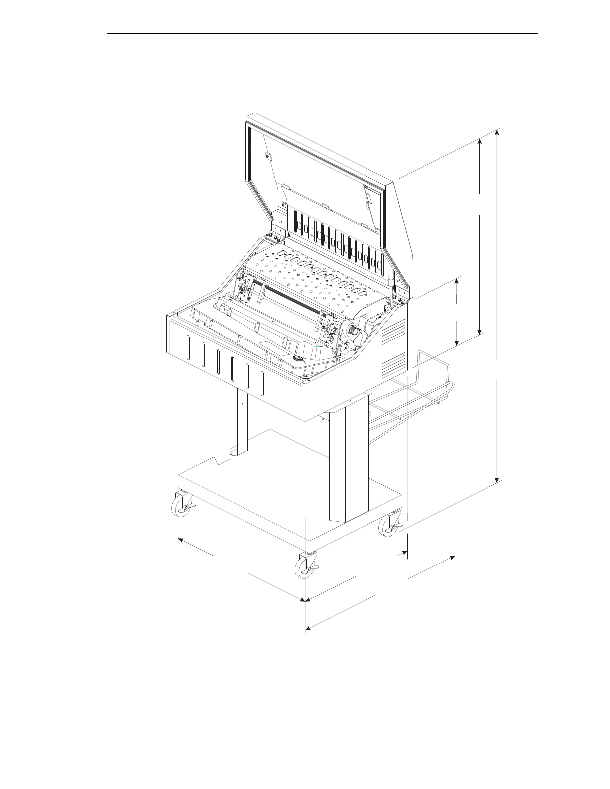
184564 REV B
184564b
29.5 in.
(74.93 cm)
11.36 in.
(28.9 cm.)
54.0 in.
(137.2 cm)
29.1 in.
(73.9 cm.)
25.92 in.
(65.8 cm)
19.1 in.
(48.5 cm)
Figure 4. Pedestal Model
23
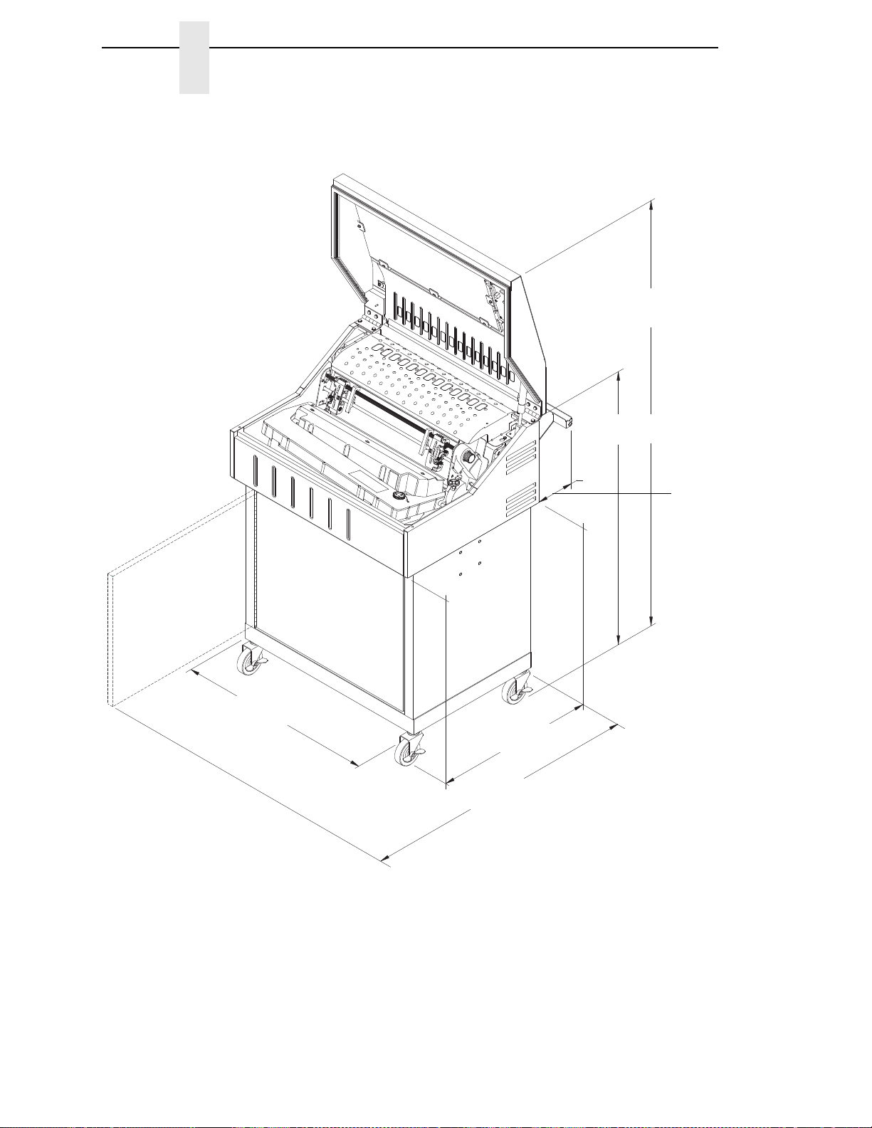
Page 24
Chapter 2
184750b
54.0 in.
(137.2 cm)
6.5 in.
(16.5 cm)
19.1 in.
(48.5 cm)
38.9 in.
(98.8 cm)
25.92 in.
(65.8 cm)
35.9 in.
(91.2 cm)
Printer Dimensions
Figure 5. Enclosed Pedestal
24
Page 25
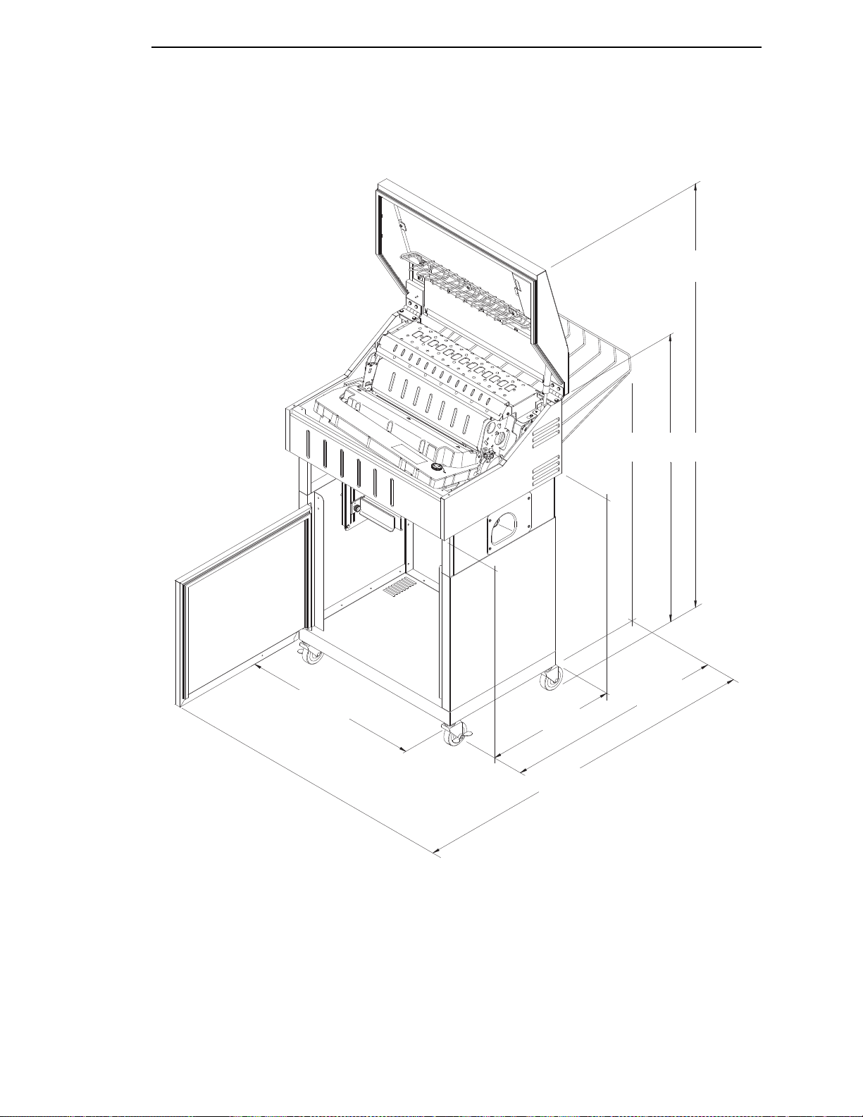
184821b
60.1 in.
(152.7 cm)
42.0 in.
(106.7 cm)
31.95 in.
(81.2 cm)
25.92 in.
(65.8 cm)
19.1 in.
(43.8 cm)
38.9 in.
(98.8 cm)
Figure 6. Zero Tear Pedestal Model
25
Page 26
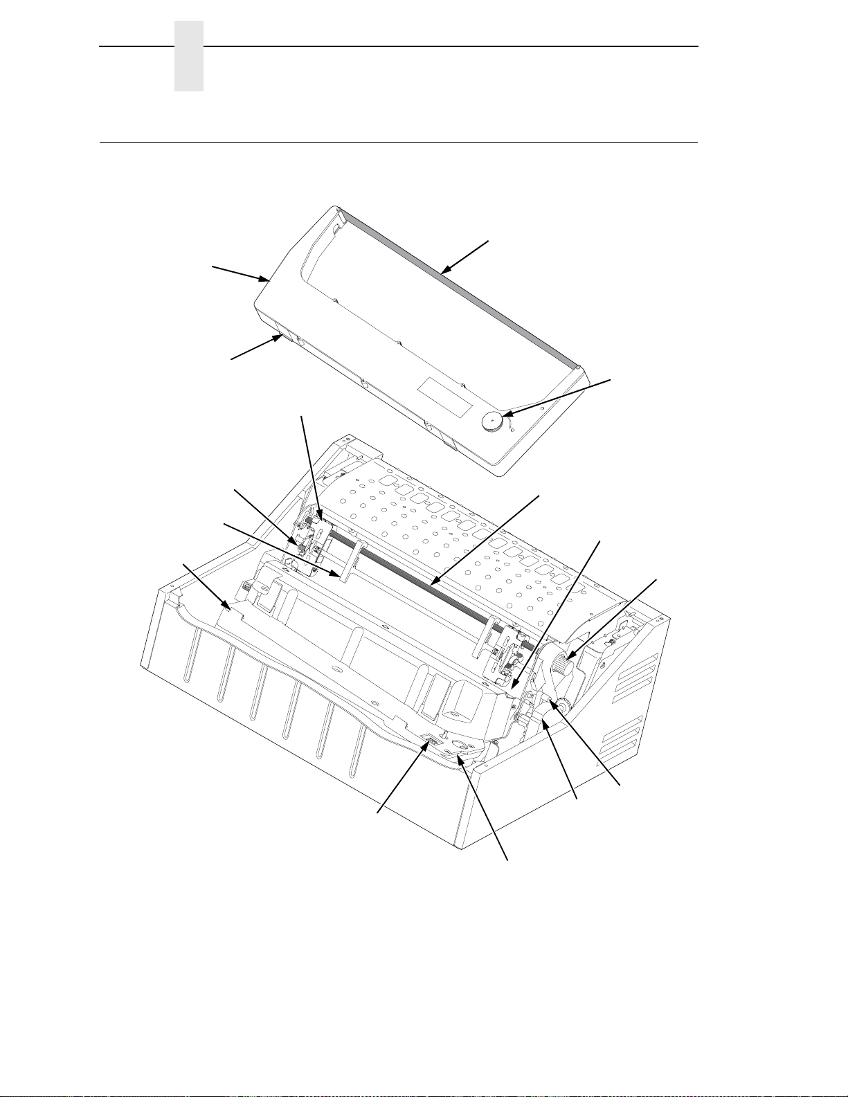
184555b
Ribbon
Ribbon
Cartridge
Ribbon
Tension Knob
Air Shroud
Assembly
Tab (2)
Tab Slot (2)
Blue Tractor
Lock (2)
Paper Support (2)
Tractor (2)
Vertical
Position Knob
Platen Lever
Splined Shaft
Platen Stop
Hammer Bank
Cover and
Ribbon Mask
Ribbon Cartridge
Interface
Chapter 2
Printer Component Locations
Printer Component Locations
Figure 7. Printer Component Locations
26
Page 27

3
Operating The Printer
Powering on the Printer
When you power on the printer, it executes a self-test. The default power-up
state is online. When the self-test completes and the software has initialized
successfully, the status indicator light turns on, indicating the printer is online.
The default value of the type of emulation you have installed appears in the
LCD display. The ribbon life remaining is shown on the bottom of the LCD
display.
If there is a fault during the self-test, the status indicator flashes and a specific
fault message appears on the display (such as “LOAD PAPER”). The alarm
also sounds if it is configured to do so. See “ LCD Message Troubleshooting
Table” on page 291 for information on fault messages and solutions.
Operating Modes
Online. In online mode, the printer can receive and print data sent from the
host. Pressing the ONLINE key toggles the printer from online to offline mode.
The status indicator is lit in online mode.
Offline. In offline mode, you can perform operator functions, such as loading
paper and setting top-of-form. Pressing the ONLINE key toggles the printer
from offline to online mode. The status indicator is off in offline mode.
Menu. In offline mode, pressing ENTER moves the printer into Menu mode.
In this mode, you can navigate through all menus and change the printer
configuration. To return to offline mode, press the ONLINE key.
Fault. In fault mode, a condition exists which must be cleared before printing
can continue. The status indicator flashes, the alarm beeps (if configured to
sound), and a descriptive fault message displays.
The current operating mode can be selected via control panel keys or can
result from routine operations such as powering on the printer.
27
Page 28
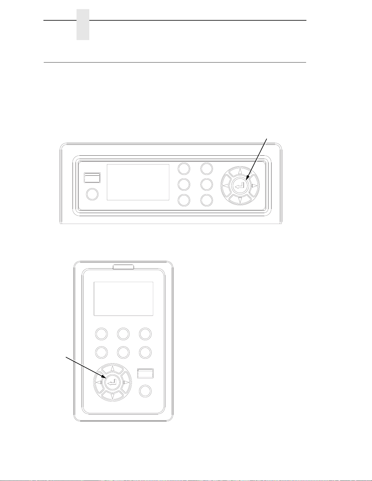
Chapter 3
ONLINE
TOF
VIEW
CONFIG
CANCEL
ADVANCE
SELECT
184554a
Cabinet Model
Enter
ONLINE
TOF
VIEW
CONFIG
CANCEL
ADVANCE
SELECT
184732a
Pedestal Model
Enter
Legend:
TOF = Set TOF (Top of Form)
VIEW = View/Eject
ADVANCE = Paper Advance
CONFIG = Print Config
SELECT = Load Config/Print Mode
1
CANCEL = Cancel Job
ONLINE = Online/Clear
NOTE:
1
Print Mode only available for H-Series
printers.
The Control Panel
The Control Panel
Figure 8 shows the keys, displays, and indicators as they appear on the
control panel. The following section provides the descriptions, and functions
of the control panel keys.
Key combinations are indicated with the plus (+) sign. For example, “Press
+ ” means to press the key and the key at the same time.
28
Figure 8. Control Panel
Page 29

Control Panel Keys
Control Panel Keys
ONLINE
Toggles the printer between online and offline modes. The key performs the
following in Online, Offline, Fault, and Menu modes:
•
Online Mode – sets the printer to Offline Mode.
•
Offline Mode – sets the printer to Online Mode.
•
Fault Mode – causes the printer to recheck the faults; if the faults are
cleared, the printer toggles to Offline Mode. If the fault condition is not
corrected before pressing the ONLINE key, the fault message reappears.
•
Menu Mode – sets the printer to Offline Mode.
NOTE: When changing to Online Mode, if the user has changed menu items
without saving the changes in a configuration, the user will be
prompted to save the changes.
ADV ANCE
Performs advance to top-of-form, as defined by the current active form length.
The key works both online and offline.
•
If online with data in the printer buffer, the data will print and then the
paper will move to the next top-of-form.
•
In the fault state, pressing ADVANCE will advance the paper. The first
press moves to the top of the next available form. All subsequent presses
advances one forms length as defined by the current active forms length.
VIEW
When the printer is online or offline, pressing this key executes the view or
eject function, depending on the setting of the menu View Function.
If online with data in the printer buffer, the data prints and the key functions as
described below.
If in a fault state, this key will be ignored.
•
View Function — When the View Function menu is set to Enable,
pressing the VIEW key for a short time (less than 1/2 second) moves the
last data printed to the tractor area for viewing. While in the view state, the
message "Printer in View" displays, pressing the UP or DOWN arrow
keys moves the paper up or down in 1/72 inch increments. This is done to
align the image within a pre-printed form, for example. Refer to the UP
and DOWN key functions for additional details on the microstep feature.
Pressing VIEW a second time moves the paper back to the adjusted print
position.
29
Page 30

Chapter 3
The Control Panel
•
Eject Function — When the VIEW key is pressed and the View Function
menu is set to Disable, or when the View Function menu is set to Enable
and the VIEW key is pressed for a long time (more than 1/2 second), the
bottom of the last printed form will move to the tear bar position as set by
the Tear Bar Dist. menu value. The message "READY TO TEAR/EJECT
To Return" displays. While in this position, pressing the UP or DOWN
arrow keys moves the paper up or down in 1/72 inch increments. Refer to
the Up and Down key functions for additional details on the microstep
feature. When the VIEW key is pressed a second time, the printer will
move the paper either forward or backward to enable printing on the next
available form.
CANCEL
In offline mode, this key cancels all data in the print buffer, if enabled in the
“ADVANCED USER Menu” (see page 220). The print buffer is cleared without
printing any of the data and the current paper position is set as the top-ofform. If this function is disabled, the CANCEL key will be ignored.
NOTE: 1. Use of this key will cause loss of data.
2. For OpenPrint products, pressing the CANCEL key advances the
paper to the next TOF.
TOF
Sets the top-of-form on the printer. This key is active only when the printer is
offline and will not operate if the printer is in a fault condition. The paper
moves down to the print position and aligns to the top-of-form. Refer to the
Quick Setup Guide for complete instructions on how to set the top-of-form.
NOTE: If there is any data in the buffer, the paper will move to the last print
position.
CONFIG
In offline mode, CONFIG prints the current short configuration. This key
requires a confirmation with the ENTER key; pressing any other key will exit
from this function. See “The Configuration Menus” on page 53 for an
explanation of configuration menus.
SELECT
In offline mode, this key allows for fast selection of any of the previously
stored configurations. Pressing this key causes the printer to cycle through
the following configuration load options: Factory, Cfg 1, Cfg 2, Cfg 3,..., Cfg 8.
For H-Series models, this key can be alternatively configured to select Print
Mode.
30
Page 31

Control Panel Keys
ENTER ( ↵ )
When navigating the configuration menus, the Enter key (referenced by the
symbol ↵ ) selects the currently displayed option value as the active value. An
asterisk (*) appears next to the active value on the display. Enter is also used
for starting and stopping printer tests and generating a configuration printout.
NOTE: The Enter key must be unlocked to execute the select function.
See UP + DOWN, later in this section.
The ENTER key lock and unlock function can be configured to be a
key combination other than + (see page 235).
•
In Offline mode, pressing the Enter key places the printer in Menu mode.
This will bring up a set of icons to select.
•
In Menu mode (at the icon menu level), pressing the Enter key moves
down into the menu tree of the highlighted icon.
•
Within a menu tree: if the highlighted menu contains submenus instead of
a selectable parameter, pressing the Enter key will go into the submenu.
If the highlighted menu is a display only menu, then pressing the Enter
key performs no function. If the highlighted menu has selectable
parameters, pressing the unlocked Enter key will select the displayed
parameter. An asterisk (*) displays next to the selected parameter.
•
If the highlighted menu is an executable menu, pressing the unlocked
Enter key will cause the function associated with the executable menu to
run. If the ENTER key is locked, pressing the Enter key for highlighted
menus that are executable or contain selectable parameters will cause
the message, THE
NOTE: Press the UP and Down keys at the same time to lock/unlock
the
↵
key.
For special Network Address menus or String menus, pressing the Enter key
will move down into a special multiple segment setting menu. Exit this menu
by pressing Enter again to save changes or Cancel to exit without saving
changes. This key is inactive in all other modes.
UP or DOWN ( or
Moves up or down between levels in the configuration menus and makes
vertical forms adjustment. After pressing VIEW, press or to adjust the
paper up or down in 1/72 inch increments for fine vertical forms alignment.
When the printer is in offline mode, press or to move through levels in
the configuration menus.
↵
KEY IS LOCKED, to display momentarily.
)
UP + DOWN ( + )
Locks and unlocks the ENTER key.
NOTE: The ENTER key lock and unlock function can be configured to be a
key combination other than + (see page 235).
31
Page 32

Chapter 3
The Control Panel
PREV or NEXT ( or )
Moves between the options on the current level of configuration menu. In the
configuration menu, press
through the menu selections on the same level.
to scroll backward or press to scroll forward
PREV + NEXT ( + )
When both keys are pressed simultaneously, the printer will reset to the
power-up configuration and reset its internal state (in offline mode).
+ ONLINE (IPDS Emulation only)
In offline mode, press + ONLINE. If there is data in the printer buffer, the
printer will be placed in online mode, print one page, and return to the offline
mode. This action can be repeated until the end of a print job. Only one page
prints each time you press + ONLINE. If there is no data in the printer
buffer, the printer is placed in online mode.
In the fault state, + ONLINE does not work.
+ ADVANCE (IPDS Emulation only)
In offline mode, press + ADVANCE. The printer will perform a reverse
linefeed. If you hold down the + ADVANCE keys for longer than
1/2 second, the printer moves to the previous top-of-form position. If there is
data in the printer buffer, the data does not print.
In the fault state, + ADVANCE does not work.
+ VIEW (IPDS Emulation only)
In offline mode, press + VIEW. If there is data in the IPDS printer buffer, the
printer will be placed in online mode, print one line, and return to offline mode.
This action can be repeated until the end of the job. This function prints only
one line of text. If the data is not text, only 1/6 inch prints. If there is no data in
the printer buffer, the printer is placed in online mode for one second and then
returns to offline mode.
In the fault state, + VIEW does not work.
Ribbon Life Indicator
The bottom of the LCD displays the remaining life of the currently installed
ribbon. The default settings for this feature should match the requirements for
most applications; no special user setup is needed. If your particular
application requires darker printing or can tolerate lighter printing, the ribbon
end point can be adjusted as appropriate. Please refer “Ribbon End Point” on
page 90.
32
Page 33

Cancel a Print Job
Cancel a Print Job
The procedure to cancel a print job depends on the printer emulation and your
application software. Contact your system administrator for additional
information.
1. If the printer is online, press ONLINE to place the printer in offline mode.
2. From the host system, stop the print job.
NOTE: If the print job is not stopped from the host system before pressing
CANCEL, the print job continues with data missing when the printer
returns to online mode. Exercise caution to prevent unwanted data
loss occurrences, as this function deletes unprinted data in the
printer. This function is active only in offline mode; the purpose of this
function is to eliminate the necessity of printing unwanted data when
print jobs are canceled.
3. Press CANCEL.
NOTE: You may need to enable the Cancel option on the front panel.
See “ADVANCED USER Menu” on page 220 for details.
4. Set the top-of-form. Refer to the Quick Reference Guide.
33
Page 34

Chapter 3
184737a
184738b
Cabinet Model
Paper Slot
Metal Paper Guide
(2000 lpm only)
Tabletop Model
Paper Slot
184558b
184739b
Paper
Slot
Pedestal Model
Wire
Guide (2)
Enclosed Pedestal Model
Wire
Guide (2)
Paper Slot
Operational Procedures
Operational Procedures
This section contains routine printer operating procedures on how to:
•
reload paper
•
unload paper
Reload Paper
Do this procedure when “LOAD PAPER” displays. (This message occurs
when the last sheet of paper passes through the paper slot.) This procedure
reloads paper without removing the last sheet of the old paper supply, while
retaining the current top-of-form setting.
34
Figure 9. Paper Slot Location
Page 35

Reload Paper
184936a
Zero Tear Pedestal Model
Paper Slot
Wire Guide (2)
Upper Paper Guide
Figure 9. Paper Slot Location (continued)
1. Raise the printer cover. Raise the platen lever as far as it will go.
(See Figure 7 on page 26 for the location of the lever.)
NOTE: Do not open tractor doors or remove the existing paper.
2. Tabletop models: place the paper supply on the table underneath the
printer, centered under the paper slot. See Figure 9 on 34.
Cabinet models: open the front door and align the paper supply with the
label on the floor.
Pedestal models: place the paper supply on the floor of the printer,
centered under the paper slot.
Enclosed pedestal and Zero Tear Pedestal models: open the front
door and place the paper supply inside the printer, on the floor of the
cabinet.
3. Ensure the paper pulls freely.
4. Feed the paper up through the paper slot (see Figure 9). It may be easier
to feed one corner of the new paper up through the slot first. When this
corner can be grasped from the top, rotate the paper back to the normal
position.
NOTE: If you are using thick, multi-part forms and are unable to load the new
paper over the existing paper, go to step 15.
5. Hold the paper to prevent it from slipping down and through the paper
slot.
35
Page 36

Chapter 3
184565a
New Paper
Existing Paper
Operational Procedures
Figure 10. Loading New Paper into the Printer
6. Pull the new paper above and behind the ribbon mask, but in front of the
existing paper. See Figure 7 on page 26 for the ribbon mask location.
If necessary, gently press the existing paper back.
7. Align the top edge of the new paper with the top perforation of the existing
paper.
8. Load the new paper over the existing paper. Open and load the tractors
one at a time to prevent the paper from slipping.
NOTE: Make sure that the top edge of the new paper lines up with the top
horizontal perforation of the last page.
36
Page 37

Reload Paper
183444b
183446b
Platen Lever
Vertical Position
Knob
Platen Stop
Knob
A
Platen
Stop
183445b
Paper Thickness
Indicator
A
Figure 11. Setting the Platen Lever
9. Turn the platen stop knob clockwise or counterclockwise to match the
paper thickness. (The A-B-C scale corresponds approximately to 1-, 3-,
and 6-part paper thickness).
NOTE: If you are using the same thickness of paper, there is no need to
readjust.
10. Lower the platen lever until it stops.
11. Press ONLINE to remove the “LOAD PAPER” fault message from the
display.
12. Press ADVANCE several times to make sure the paper feeds properly
beyond the tractors and over the lower paper guide. Feed sufficient paper
to ensure the paper stacks correctly.
13. Close the printer top cover. Close the cabinet front door.
14. Press ONLINE
to place the printer in online mode and resume printing.
37
Page 38

Chapter 3
TOF
TOF
183441b
Paper
Left Tractor Door
Left Tractor Lock
Operational Procedures
NOTE: Perform steps 15 to 31 only if you are unable to load the new paper
over the existing paper.
15. Open both tractor doors.
16. Remove the old paper from the tractors. Allow the paper to fall into the
paper supply area.
17. Feed the new paper up through the paper slot. Hold the paper to prevent
it from slipping down through the paper slot (see Figure 9 on page 34).
38
Figure 12. Loading Paper on the Left Tractor
18. Pull the paper above and behind the ribbon mask. See Figure 7 on
page 26 for the ribbon mask location.
19. Load the paper on the left tractor.
20. Close the tractor door.
Page 39

Reload Paper
183442b
Paper
Paper Scale
Tractor
Tractor
Splined Shaft
Tractor Lock
CAUTION
Figure 13. Positioning the Left Tractor to Avoid Damage
To avoid damage to the printer caused by printing on the platen, always
position the left tractor unit directly to the left of the “1” mark on the
paper scale.
21. Normally, you should not need to adjust the position of the left tractor.
If adjustment is necessary, unlock the left tractor by placing the tractor
lock in the middle position. Slide the tractor until it is directly to the left of
the number “1” on the paper scale and lock it. (You can also use the
paper scale to count columns.)
39
Page 40

Chapter 3
TO
F
TO
F
T
OF
TOF
183443b
Tractor Lock
Tractor Door
Operational Procedures
Figure 14. Loading Paper onto the Sprockets
22. Unlock the right tractor.
23. Load the paper onto the sprockets and close the tractor door.
If necessary, slide the right tractor to remove paper slack or to adjust for
various paper widths. Then, lock the tractor.
40
Page 41

Reload Paper
184738b
184737a
Cabinet Model
Paper Slot
Metal Paper Guide
(2000 lpm only)
Tabletop Model
Paper Slot
Upper Paper
Guide
Upper Paper
Guide
184739b
184558 REV B
184558b
Paper
Slot
Pedestal Model
Wire
Guide (2)
Enclosed Pedestal Model
Wire
Guide (2)
Paper Slot
Upper Paper
Guide
Upper Paper
Guide
Figure 15. Using the Paper Guide to Orient the Paper
41
Page 42

Chapter 3
184936a
Zero Tear Pedestal Model
Paper Slot
Wire Guide (2)
Upper Paper Guide
Operational Procedures
Figure 15. Using the Paper Guide to Orient the Paper (continued)
24. Tabletop, Pedestal, or Zero Tear Pedestal models:
Using the vertical position knob to move the paper up, guide the paper
over the upper paper guide and through the slot to the rear of the top
cover.
25. Press ADVANCE several times to make sure the paper feeds properly
beyond the tractors and over the lower paper guide. Feed sufficient paper
to ensure the paper stacks correctly.
26. Ca binet models:
Open the cabinet rear door. Make sure the paper is aligned with the label
in the output area (inside the cabinet). Close the front and rear doors.
42
Page 43

Reload Paper
TOF
T
OF
TOF
TOF
184752a
TOF Indicator
Perforation
Vertical
Position
Knob
Figure 16. Aligning the Perforation with the TOF Indicator
27. Align the top of the first print line with the TOF indicator on the tractor by
rotating the vertical position knob. For best print quality, it is
recommended that the top-of-form be set at least one print line or more
below the perforation.
NOTE: For exact positioning, press the VIEW key to move the last data
printed to the tractor area for viewing. While in View mode “Printer in
View” displays. Press the Up or Down Arrow keys to move the paper
vertically in small increments. Pressing the VIEW key a second time
moves the paper back to the adjusted print position. The key works
both online and offline provided that the printer is in View mode. (This
procedure is applicable for both the cabinet and pedestal models.)
43
Page 44

Chapter 3
183444 REV B
183444b
183446b
Platen Lever
Vertical Position
Knob
Platen Stop
Knob
A
Platen
Stop
183445b
Paper Thickness
Indicator
A
Operational Procedures
Figure 17. Adjusting the Platen Lever
28. Turn the platen stop knob clockwise or counterclockwise to match the
paper thickness. (The A-B-C scale corresponds approximately to 1-, 3-,
and 6-part paper thickness. Adjust until you have the desired print
quality).
NOTE: The platen stop allows you to set an optimum and consistent
thickness that is not affected when opening and closing the platen
lever.
29. Lower the platen lever until it stops.
30. Press ONLINE to clear any fault messages (such as “LOAD PAPER”)
from the LCD.
31. Press TOF. The top-of-form you have set moves down to the print
position. If there is data in the buffer, the paper moves forward to the last
print position on the next page.
32. Press ONLINE and close the printer cover.
44
Page 45

Unload Paper
TO
F
T
O
F
TOF
T
O
F
183477b
Paper
Perforation
Unload Paper
1. Press ONLINE to place the printer in offline mode and open the printer
cover.
2. For cabinet models, open the cabinet rear door. For models with the
power stacker installed, press the STACKER UP key on the rear control
panel.
Figure 18. Unloading the Paper from the Printer
3. Tear off the paper at the perforation.
4. Allow the paper to fall to the back of the printer and into the paper
stacking area.
5. For pedestal models, remove the stacked paper from the paper tray.
45
Page 46

Chapter 3
183478b
Paper
Power Stacker
Operational Procedures
Figure 19. Removing Stacked Paper from the Printer
6. For cabinet models, remove the stacked paper from the rear cabinet floor.
For cabinet models with the power stacker installed, remove the paper
from the wire paper tent and press the STACKER DOWN key to lower the
stacker mechanism.
7. Close the cabinet rear door.
46
Page 47

Unload Paper
184571a
T
OF
T
O
F
Platen Lever
Tractor Door
CAUTION
Figure 20. Completely Removing the Paper
8. To completely remove the paper from the printer:
a. Raise the platen lever as far as it will go and open both tractor doors.
Be careful when pulling any paper backward through the paper path,
especially when using a label stock. If you are not careful, labels can
detach and adhere to the printer within the paper path, where only an
authorized service representative can remove them.
b. Open the cabinet front door.
c. Gently pull the paper down through the paper slot. Allow the paper to
fall into the paper supply area.
d. Remove the paper from the paper supply area.
47
Page 48

Chapter 3
Integrated Print Management System
Integrated Print Management System
The P8000 has a feature that automatically monitors and communicates the
status of the ribbon life to help the operator know when to change ribbons.
Using an ink delivery system called the Cartridge Ribbon System (CRS), the
printer can automatically detect when a new or used ribbon is loaded, and all
ribbon properties. The ribbon is contained in a plastic box (the cartridge) and
feeds only in one direction. The CRS contains an interface board that allows
communication between the printer and the cartridge. Using the CRS, the
P8000 automatically detects when a new or used ribbon is installed and
determines the ribbon’s length, ink color, and expected yield. The ribbon life,
starting from 100% when new and decreasing to 0% when depleted, is always
displayed on the control panel. See Figure 8 on page 28.
When the ribbon life reaches 2%, a warning message “RIBBON UNDER 2%/
Change RBN soon” appears on the control panel display. The control panel
status indicator lamp flashes. The printer will continue printing in this condition
until the ribbon life reaches 0% at which time, printing will stop. The ribbon
may be changed at any time while the printer is in the “CARTRIDGE AT END
POINT/Change Cart” condition without losing data in the printer’s buffer. If a
new ribbon is loaded, the system automatically detects the change, clears the
condition when the platen is closed, and restarts the life at 100%. If a partially
used ribbon is loaded, the system continues the life at the percentage
indicated for the used ribbon.
You may also resume printing for approximately two more minutes without
changing the ribbon by pressing the ONLINE key twice. This may be done as
many times as needed to complete the job in progress.
Ribbon usage information is calculated by maintaining a count of impressions
(dots) that is stored on the ribbon cartridge and updated periodically so that
the cartridge can be used on a different printer with the information intact. This
allows the system administrator to have precise control over print quality and
consumable costs. The accurate presentation of available ribbon life allows
for efficient planning of print jobs. For example, if the displayed ribbon life
were low, you can install a new ribbon before printing a large print job.
Output Darkness
By default the system is configured to meet most user requirements.
However, some applications require that the output remains darker than the
nominal set point while some applications are less critical and could tolerate a
lighter final image. The system can easily adjust to this variability. A setting
under the Printer Control menu is available that allows the user to adjust the
final output. The range is as follows:
Normal (Default)
Darker +1 through +6
Lighter -1 through -10
The ribbon life indicator always cycles between 100% and 0%, but if a darker
setting is selected, zero will be reached more quickly. If a lighter setting is
selected, the system will extend the amount of printing it takes to reach zero.
48
Page 49

Loading a Used Ribbon Cartridge
Loading a Used Ribbon Cartridge
You can take the ribbon cartridge off the printer and reload it at a later time.
The ribbon life gauge automatically updates to reflect the correct remaining
capacity.
NOTE: Since the ribbon usage information is stored on the ribbon cartridge,
you can reload a partially used cartridge onto a different printer.
Lighter or Darker Print
The ribbon life value as determined by the Integrated Print Management
System is factory set so that the image quality at the end of the ribbon life is
as good as it was when the ribbon was new. You may adjust the ribbon end
point for a lighter or darker image as required for your printing needs.
See “PRINTER CONTROL Menu” on page 216.
49
Page 50

Chapter 3
TOF
TOF
184559a
Blue Tractor
Door (2)
Platen Lever
Integrated Print Management System
Changing Ribbon Cartridge
Before changing the ribbon cartridge, determine whether at the end of ribbon
life if you want to make the print lighter (extend the ribbon life) or darker
(shorten the ribbon life). If you want to make the print lighter or darker, go to
“Ribbon End Point” on page 90 and follow the procedures for adjusting the
image density. If you are satisfied with the print darkness, continue with the
following steps.
NOTE: Ribbon cartridge instructions and illustrations shown in the following
section are for the pedestal model. Follow the same procedures for
the cabinet model.
50
Figure 21. Preparing to Load the Ribbon
1. Open the printer cover.
2. Raise the platen lever as far as it will go.
3. Close the tractor doors.
4. Remove the old ribbon cartridge and discard properly.
Page 51

Changing Ribbon Cartridge
184555b
Ribbon
Ribbon
Cartridge
Ribbon
Tension Knob
Air Shroud
Assembly
Tab (2)
Tab Slot (2)
CAUTION
Figure 22. Installing the Ribbon Cartridge
5. Remove the ribbon slack on the new ribbon cartridge by turning the
ribbon tension knob clockwise.
Do not turn the ribbon tension knob counterclockwise. This could
damage the ribbon cartridge.
6. Hold the cartridge at an angle, so that the rear side nearest you is lower
than the side with the ribbon. Find the two tabs on the outside of the
cartridge and place them into the corresponding slots on the air shroud
assembly (see Figure 22).
51
Page 52

Chapter 3
184557a
184556b
Ribbon
Cartridge
A
Hammerbank
Cover
Ribbon Mask
Ribbon Cartridge
Ribbon
Ribbon Tension Knob
A
Integrated Print Management System
CAUTION
Figure 23. The Ribbon Cartridge Snapped in Place
7. Rock the cartridge downward, making sure that the ribbon goes between
the guide and the mask (see Figure 23). You will feel it snap into place.
Make sure that the ribbon does not twist or fold over.
8. Turn the ribbon tension knob clockwise a few times to make sure the
ribbon tracks correctly in the ribbon path.
9. Close the platen lever.
10. Close the printer top cover.
11. Press the ONLINE key twice to return the printer to operation.
52
Page 53

4
The Configuration Menus
Configuration Overview
To print data, the printer must respond correctly to signals and commands
received from the host computer. Configuration is the process of matching the
printer's operating characteristics to those of the host computer and to
specific tasks, such as printing labels or printing on different sizes of paper.
The characteristics which define the printer's response to signals and
commands received from the host computer are called configuration
parameters.
You can configure the printer using the configuration menus and the control
panel or by sending control codes in the data stream from a host computer
attached to the printer. This chapter provides an introduction to configuring
the printer and includes the configuration menus available (depending on
which emulation you have installed in the printer).
IMPORTANT
Configuration directly affects printer operation. Do not change the
configuration of your printer until you are thoroughly familiar with the
procedures in this chapter.
Main Menu
The Main Menu is organized based on the following firmware types:
1. P8000 Standard Firmware (IPDS/PGL/VGL/LP+)
2. P8000 TN Firmware (TN/PGL/VGL/LP+)
3. P8000 PCL-II Firmware (PCL-II/PGL/VGL/LP+)
4. P8000 LG Firmware (LG/PGL/VGL/LP+)
5. P8000 ANSI Firmware (ANSI/PGL/VGL/LP+)
6. OpenPrint P8000 Standard Postscript/PDF Firmware (PS/PGL/VGL/LP+)
7. OpenPrint P8000 HD Postscript/PDF Firmware (PS)
8. H-Series Firmware (LP+)
9. Indian Language Firmware (LP+)
53
Page 54

Chapter 4
Configuration Overview
Changing Parameter Settings
You may change a printer parameter setting, such as line spacing or forms
length, either by pressing keys on the control panel or by sending emulation
control codes in the data stream from a host attached to the printer. The
control panel allows you to configure the printer’s resident set of configuration
menus. An example procedure for using the control panel to change
parameter settings begins on page 58.
When control codes are sent from a host attached to the printer, they override
control panel settings. For example, if you set the line spacing to 6 lpi with the
control panel, and application software later changes this to 8 lpi with a control
code, the control code overrides the control panel setting.
Saving Parameter Settings
The parameter settings that you have changed can be permanently stored in
the printer’s memory as a configuration. See “Auto Save Configuration” on
page 62 and “Saving Your New Configuration” on page 63.
You may also save your new configurations using the PTX_SETUP command
host control code. See your IGP/PGL Programmer's Reference Manual for
details.
Default and Custom Configurations
A configuration consists of a group of parameter settings, such as line
spacing, forms length, etc. Your printer provides a fixed default configuration
and allows you to define several custom configurations for use with particular
print jobs. The factory default configuration can be loaded, but it cannot be
altered.
Eight configurations can be modified for unique print job requirements. The
“Save Config.” option allows you to save eight groups of parameter settings in
memory as custom configurations numbered from 1 through 8. An
explanation on how to save a set of parameter values as a custom
configuration using the “Save Config.” menu option begins on page 63.
54
Page 55

Navigating the Menus
ONLINE
OR
OR
ENTER
+
Navigating the Menus
To manipulate configurations review the following instructions about
navigating through the menus.
You must be Menu mode to navigate the menus.
Press to toggle between ONLINE and OFFLINE.
Press ENTER to enter Menu mode. Menus are
accessed only in Menu mode.
Scroll up, down, left, or right through the icons to
highlight the area of interest.
Press to enter the area of interest. This will take you
into that section and list three menu selections, with
the middle selection highlighted.
NOTE: For display languages in Korean, Simplified
Chinese, or Traditional Chinese, only one
menu selection is shown at a time.
Press to move up or down through the menu
selections. The highlighted menu is the active
selection.
Press to scroll through the available choices for the
highlighted menu. If the highlighted menu contains
submenus, these buttons have no effect and the
message “
↵
for Submenu” will display.
Press to confirm selection. For normal menus, this will
change or execute the menu. If the selection has
submenus, the submenu will be entered.
Press to lock and unlock the ENTER key. The ENTER
key is locked by default to prevent you from
accidentally changing the printer configuration. The
lock and unlock function can be configured to be other
than + (See “Set Lock Key” on page 235.)
55
Page 56

Chapter 4
CANCEL
ONLINE
Top Level Menu Overview
To experiment with navigating the menus, use the example on the next page
as a tutorial.
Top Level Menu Overview
When entering Menu mode, the user will see top level menus represented as
icons as shown below. Use the navigation buttons up, down, right, and left to
highlight the desired icon. As the user navigates, the name of the top level
menu displays on the top line of the LCD.
Press to return to the previous menu level.
Press to return to Offline mode. If changes were made,
the user will be prompted to save or discard the
configuration.
Table 3 provides brief descriptions of first level configuration menu options:
T able 3. Icon Level Menus
Menu Icon Menu Description
QUICK SETUP These options allow quick access to the most
frequently changed or inputted parameters during the
installation of the printer.
PRINTER
CONTROL
ADVANCED USER This menu allows you to select several advanced
CONFIG. CONTROL These options allow you to save, print, load, delete,
This menu allows you to select parameters common to
a general user, such as display language and Barcode
quality.
operating parameters for the printer, such as the speed
at which paper will advance when slewing. The SURE
SCAN menu for OpenPrint models is under this menu.
name, and reset entire sets of configuration
parameters.
56
Page 57

Top Level Menu Overview
T able 3. Icon Level Menus
Menu Icon Menu Description
HOST INTERFACE These options allow you to select either the Serial
®
RS-232, Centronics
parallel, Ethernet™, IEEE® 1284
parallel, or Auto Switching interface for the printer. This
menu also allows you to configure several parameters
for each interface.
NETWORK SETUP This option allows you to select from Ethernet Address
options and Ethernet Parameters options.
EMULATION This menu allows you to configure the options which
are available for the current operating (active)
emulation. For example, if LinePrinter+ is the active
emulation, then the LinePrinter+ emulation options can
be configured using this menu. The ACTIVE IGP
EMUL and ACTIVE EMULATION menus are under
this menu.
Navigating the Menus
DIAGNOSTICS This menu includes the diagnostic tests, system
memory, software build part number, Feature File
(if one exists), the shuttle type, and statistics of the
printer. The Printer Mgmt menu is under this menu.
57
Page 58

Chapter 4
. . .
OFFLINE
QUICK
SETUP
CONFIG.
CONTROL
Load
Config.
Save
Config.
Print
Config.
Power-Up
Config.
Delete
Config.
Protect
Configs.
Cfg 1*
Cfg 2 - Cfg 8
Current Short*
Current Full
Factory
Power-Up
All
Cfg 1 - Cfg 8
Factory*
Cfg 1 - Cfg 8
All*
Cfg 1 - Cfg 8
Disable*
Enable
* = Factory Default
Name
Configs
(see Example 2
on page 66)
Factory*
Cfg 1 - Cfg 8
Reset Cfg
Names
Cfg 1*
Cfg 2 - Cfg 8
All
Auto
Save
Enable*
Disable
Top Level Menu Overview
Changing Parameters Example
A configuration consists of several parameters. The default factory
configuration has a starting set of parameters. In the configuration menu
above, and in all the configuration menus in this chapter, the factory default
values are indicated by an asterisk (*).
Your print jobs may require parameter values which vary from the default
settings. This section provides an example procedure for changing individual
parameter values.
58
Page 59

Changi ng Parameters Example
ONLINE
ENTER
+
UNTIL
ENTER
The following procedure shows how to change and save the settings for the
Barcode Quality and Panel Display options. Use these guidelines to navigate
the configuration menus and change other parameters.
Step Press LCD Notes
1. Make sure the printer is on.
2.
3. Shows the top level icons.
4. Allows you to make configuration changes.
5.
6.
59
Page 60

Chapter 4
UNTIL
UNTIL
ENTER
UNTIL
UNTIL
ENTER
Step Press LCD Notes
7.
8.
9.
Top Level Menu Overview
10. The * indicates this choice is active.
11.
12.
13. The * indicates this choice is active.
60
Page 61

Changi ng Parameters Example
+
ONLINE
ONLINE
ENTER
Step Press LCD Notes
14. Locks the ENTER key.
15. Press ENTER to go back into the menus or
16. Configuration changes were detected and
17A. Saves the Configuration as Config 1 then
17B. Places the printer online after permanently
press ONLINE again to go ONLINE.
you are prompted to save the configuration
permanently or temporarily, to cancel
changes, or restore the Factory
Configuration.
returns the printer ONLINE.
saving the configuration changes as
Config 1.
18. The printer is ready for operation
61
Page 62

Chapter 4
Top Level Menu Overview
Auto Save C onf igu r atio n
If the user makes a menu change and attempts to place the printer online
without saving the changes to a configuration, the following prompt displays:
The active option is highlighted. Use the Up and Down keys to scroll through
the different options; the keys will loop at the top and bottom options. The
(Enter) key selects the highlighted option. After performing the selected
option, the printer will go to Online mode.
NOTE: Only the Up, Down, and Enter keys work at the Menu Changes
Detected prompt.
•
Save Permanently (factory default). This option causes the printer to
save the configuration to the active configuration and make the active
configuration the Power-Up default configuration. If the active
configuration is the Factory Configuration, the printer will save the
configuration to an open configuration and make that open configuration
the Power-Up default configuration.
↵
If no open configuration is available, the user must decide which
configuration to overwrite. In this case the printer will display the Save
Configuration menu, otherwise, the printer will go Online.
•
Save Temporarily. Menu changes will be implemented, but will not be
saved once the printer is powered off.
•
Cancel Changes. This option causes the printer to reload the Active
Configuration, then go Online.
•
Restore Factory. This option will cause the printer to reload the Factory
Configuration, then go Online.
NOTE: A printer fault during the Auto Save process causes the printer to
Save Temporarily.
62
Page 63

Saving Your New Configuration
Saving Your New Configuration
The Save Config. option allows you to save up to eight custom configurations
to meet different print job requirements. Once you have changed all of the
necessary parameters, you may save them as a numbered configuration
(Example 1 on page 64) or a named configuration (Example 2 on page 66)
that can be stored and loaded later for future use. If you do not save your
configuration using the Auto Save, or this option, all of your parameter
changes will be erased when you power off the printer.
Once you have saved a custom configuration using this option, it will not be
lost if you power off the printer. You can load a configuration for a specific
print job (see “Load Config.” on page 91). You can also modify and resave it.
You may want to print your configurations (see “Print Config.” on page 91)
and store them in a safe place, such as inside the printer cabinet. If the
Protect Configs. parameter is enabled and you try to resave an existing
configuration, the new configuration will not be saved until the existing
configuration has been deleted (see “Delete Config.” on page 92).
NOTE: Once you change active emulations, any changes to the previously
selected emulation will be gone unless they have been saved.
63
Page 64

Chapter 4
ONLINE
ENTER
+
UNTIL
ENTER
Top Level Menu Overview
Example 1
This example shows how to save a configuration as a numbered
configuration, then later print it.
Step Press LCD Notes
1. Make sure the printer is on.
2.
3.
4. Allows you to make configuration changes.
5.
6.
64
Page 65

Saving Your New Configuration
UNTIL
ENTER
UNTIL
ENTER
+
Step Press LCD Notes
7.
8.
9. The * indicates this choice is active.
NOTE: We recommend that you print the configuration. To print the configuration go to Step 10. To skip this
procedure and resume printer operation, go to Step 13.
10.
11.
12.
13. Locks the ENTER key.
65
Page 66

Chapter 4
ONLINE
ONLINE
UNTIL
ENTER
Step Press LCD Notes
Top Level Menu Overview
14. Press ENTER to go back into the menus or
15. Places the printer ONLINE.
16. If you printed the configuration, store it in a safe place. The printer is ready for operation.
press ONLINE again to go ONLINE.
Example 2
This example shows how to save a configuration as a named configuration.
Step Press LCD Notes
1. Make sure the printer is on.
2. Follow Steps 2-6 from
3.
4.
5.
Example 1 (page 64).
66
Page 67

Saving Your New Configuration
ENTER
or
or
ENTER
CANCEL
UNTIL
UNTIL
Step Press LCD Notes
6.
7. Press the left or right key to choose the
8. Press the up key to select the next character
9. Configuration 2 is renamed TEST.
10.
character that is highlighted.
in the string. Press the down key to go back
to the previous character and continue
editing as necessary.
11.
12.
67
Page 68

Chapter 4
ENTER
+
ONLINE
ONLINE
Step Press LCD Notes
13. Your configuration is saved as TEST.
14. Locks the ENTER key.
Top Level Menu Overview
15. Press ENTER to go back into the menus or
16. Places the printer ONLINE.
Now you have the saved configuration for later use if needed.
press ONLINE again to go ONLINE.
Optimizing Prin t Quality
LP+, IGP/PGL, and IGP/VGL Emulations
You can optimize print quality for darker and sharper barcodes and
characters. Doing so, however, will decrease the printer speed.
To optimize print quality, you can change the values of the following
configuration parameters:
68
•
Bar Code Quality (Printer Control menu): Select “Dark” or “Draft.”
Dark prints the darkest images, but at the slowest speed. Draft prints at a
faster speed than Dark, but the characters are not as dark. (See page 217
for a written description of Bar Code Quality.)
•
Print Quality (IGP/PGL emulat ion): Select “Best” or “High.” Best prints
the darkest images, but at the slowest speed. High prints at a faster
speed than Best, but the characters are not as dark. (See page 175 for
the IGP/PGL Configuration Menu, and page 182 for a written description
of Print Quality.)
•
Print Quality (IGP/VGL emulation): Select “High.” (See page 186 for the
IGP/VGL Configuration Menu, and page 190 for a written description of
Print Quality.)
Page 69

Optimizing Print Speed
OpenPrint Postscript/PDF Emulations
You can optimize print quality for darker and sharper text and barcodes by
using the following configuration parameters:
•
Unidirectional (Printer Control menu): Select “Enable” for best quality
but reduced throughput (half speed).
•
Resolution (Postscript/PDF menu): Select higher values (horizontal by
vertical DPI) to get better print quality.
H-Series Emulations
Print quality varies based on the typeface selected. Both text and barcodes
will print using the resolution of the selected typeface.
Optimizing Prin t S peed
LP+, IGP/PGL, and IGP/VGL Emulations
The printer has been configured at the factory for optimal print speed. To
optimize print quality instead, you can change values for specific configuration
parameters such as Barcode Quality and Print Quality. Doing so, however,
will decrease the printer speed.
If you have optimized the printer for print quality, you can change it to optimize
the speed by selecting the values as follows:
•
Bar Code Quality (Printer Control menu): Select Draft.
(See page 216 for the Printer Control Menu, and see page 217 for a
written description of Bar Code Quality.)
•
Print Quality (IGP/PGL emulat ion): Select Dataprocessing.
(See page 175 for the IGP/PGL Configuration Menu, and see page 182
for a written description of Print Quality.)
•
Print Quality (IGP/VGL emulation): Select Dataprocessing.
(See page 186 for the IGP/VGL Configuration Menu, and see page 190
for a written description of Print Quality.)
OpenPrint Postscript/PDF Emulations
The printer has been configured at the Factory for optimal print quality
through the Resolution configuration parameter (Postscript/PDF menu).
However, users can reduce the horizontal, vertical, or both DPI values of this
menu to increase printer speed. The downside of using a lower DPI value is
as follows:
•
Print quality is reduced and it can be difficult to read small characters.
•
Barcodes may not get detected and optimized (barcodes are not
searched for DPI values less than 120).
Users are encouraged to use the Resolution menu to find the right
combination of Print Quality, Barcode Optimization, and Print Speed.
69
Page 70

Chapter 4
Dynamic Menu Options
H-Series Emulations
The print speed varies based on the typeface selected.
Dynamic Menu Options
The main menus for each of the different firmware types have several
footnotes based on the possible options installed with the printer. This
includes HOST IO connectivity, various hardware/mechanical options, and
software emulations and features. The P8000 products dynamically detect
options installed and only include relevant menus for the user to configure.
The following is a description of the types of installation options and their
effect on the main menu:
•
HOST INTERFACE: Ethernet related menus are only present when the
hardware is installed/enabled.
•
NETWORK SETUP: The NETWORK SETUP menu is only present when
Ethernet is installed.
•
Centronics and IEEE 1284: Options are only selectable or configurable
when the optional parallel interface card is present.
•
SureStak Power Stacker: The power stacker and auto elevator options
are available for configuration when the SureStak power stacker is
installed.
•
QUICK SETUP: This menu is a collection of popular menus to help users
quickly configure the printer. It is also affected by the installed options.
70
Page 71

Active Emula tions
The emulations present in the printer are based on the firmware installed and
the emulation options included. Both are configured from the Factory and do
not require any action from the user.
Active Emulations
Optimizing Print Speed
IMPORTANT
Firmware T ype
P8000 Standard
P8000 TN PGL/VGL
Be sure to know which type of firmware and options are purchased
(see Table 4) to understand the ACTIVE IGP EMUL, ACTIVE
EMULATION, and EMULATION main menus. H-Series and Indian
Language products only have the LinePrinter+ emulation.
Table 4. Available Firmware Types and Options
Optional
Emulations
Available
ACTIVE IGP
1
EMUL
ACTIVE
EMULATION
EMULATION
2
IPDS
IGP/PGL* N/A
IPDS
PGL/VGL
IGP/VGL N/A
IGP/PGL
LinePrinter+
IPDS
IGP/VGL
LinePrinter+
IGP/PGL* N/A IGP/PGL
LinePrinter+
IGP/VGL N/A IGP/VGL
LinePrinter+
3
PCL-II* PCL-II
P8000 PCL-II PGL/VGL N/A
IGP/PGL &
LP+
IGP/VGL &
LP+
IGP/PGL
LinePrinter+
IGP/VGL
LinePrinter+
NOTE:
* = Default Selection
1
The Active IGP EMULATION menu is only available when the PGL/VGL option is installed.
2
The ACTIVE EMULATION menu shows the options “IGP/PGL & LP+” and
“IGP/VGL & LP+” when the PGL/VGL option is installed. Otherwise, “LinePrinter+” replaces
the options.
3
The selections under the EMULATION menu is based on the ACTIVE IGP EMULATION or
ACTIVE EMULATION settings with all Optional Emulations installed.
71
Page 72

Chapter 4
Active Emulations
Table 4. Available Firmware Types and Options
Firmware T ype
Optional
Emulations
ACTIVE IGP
Available
P8000 LG PGL/VGL N/A
P8000 ANSI PGL/VGL N/A
OpenPrint P8000
Standard
4
PGL/VGL N/A
EMUL
ACTIVE
1
EMULATION
EMULATION
2
3
LG* LG
IGP/PGL &
LP+
IGP/VGL &
LP+
44/48XX-
IGP/PGL
LinePrinter+
IGP/VGL
LinePrinter+
44/48XX-ANSI
ANSI*
IGP/PGL &
LP+
IGP/VGL &
LP+
Postscript/
IGP/PGL
LinePrinter+
IGP/VGL
LinePrinter+
Postscript/PDF
PDF*
IGP/PGL &
LP+
IGP/VGL &
LP+
IGP/PGL
LinePrinter+
IGP/VGL
LinePrinter+
OpenPrint P8000 HD
4
N/A N/A N/A Postscript/PDF
H-Series N/A NA N/A LinePrinter+
Indian Language N/A NA N/A LinePrinter+
NOTE:
* = Default Selection
1
The Active IGP EMULATION menu is only available when the PGL/VGL option is installed.
2
The ACTIVE EMULATION menu shows the options “IGP/PGL & LP+” and
“IGP/VGL & LP+” when the PGL/VGL option is installed. Otherwise, “LinePrinter+” replaces
the options.
3
The selections under the EMULATION menu is based on the ACTIVE IGP EMULATION or
ACTIVE EMULATION settings with all Optional Emulations installed.
4
The Postscript emulation cannot process color documents. All documents sent to the
OpenPrint printer must be either gray scale or black and white.
72
Page 73

OFFLINE
CONFIG.
CONTROL
page 91
HOST
INTERFACE
page 93
Load Config.
Save Config.
Print Config.
Delete Config.
Power-Up Config.
Protect Configs.
Name Configs
Reset Cfg Names
Auto Save
Active Host
Auto Switching
Centronics
1
Serial
IEEE 1284
1
USB
NETWORK
SETUP
1
page 105
Ethernet Address
1
Ethernet Params
1
QUICK
SETUP
page 82
Active Host
ZTP DataTime
4
ZTP WaitTime
4
ZTP TearDist
4
ACTIVE IGP EMUL
1
PGL SFCC
3
VGL SFCC
2
Active Protocol
Form Length
Form Width
Select CPI
Select LPI
P-Series SFCC
Ribbon End Point
Save Config.
Power-Up Config.
Open Platen @ BOF
Slow Paper Slew
EMULATION
page 111
ACTIVE IGP EMUL
IPDS
2
LinePrinter+
IGP/PGL
3
IGP/VGL
2
PRINTER
CONTROL
page 216
ZTP SETTINGS
4
Ribbon End Point
Open Platen @ BOF
Bar Code Quality
Tear Bar Dist.
5
View Function
Unidirectional
Display Language
Panel Display
Accented Chars.
DIAGNOSTICS
page 238
Printer Tests
Test Width
Phase Value
Paper Out Dots
System Memory
Print Statistics
Software Build
Feature File
6
Shuttle Type
Auto Dump
Printer Mgmt
ADVANCED
USER
page 220
PTX_SETUP Option
Hex Dump Mode
Power-up State
Downloaded Fonts
PMD Fault
Power Stacker
1
Auto Elevator
1
Auto Locking
Main File System
SD File System
1
Set Sharing
Shuttle Timeout
Slow Paper Slew
Alarm
Power Saver Time
Pwr Save Control
Cancel Key
Rcv. Status Port
Ret. Status Port
Set Lock Key
RBN Low Warn@
RBN Low Action
RBN End Action
Print Energy
7
Disp. Intensity
1
If installed.
2
If VGL is selected from the ACTIVE IGP EMUL menu.
3
If PGL is selected from the ACTIVE IGP EMUL menu.
4
Available for Zero Tear Pedestal printers only.
5
Available for pedestal printers only.
6
If a Feature File has been downloaded.
7
Available for 1000 lpm printers only.
P8000 Standard Firmware
P8000 Standard Firmware
73
Page 74

OFFLINE
CONFIG.
CONTROL
page 91
HOST
INTERFACE
page 93
Load Config.
Save Config.
Print Config.
Delete Config.
Power-Up Config.
Protect Configs.
Name Configs
Reset Cfg Names
Auto Save
Active Host
Auto Switching
Centronics
1
Serial
IEEE 1284
1
USB
NETWORK
SETUP
1
page 105
Ethernet Address
1
Ethernet Params
1
QUICK
SETUP
page 82
Active Host
ZTP DataTime
4
ZTP WaitTime
4
ZTP TearDist
4
ACTIVE IGP EMUL
1
PGL SFCC
2
VGL SFCC
3
Active Protocol
Form Length
Form Width
Select CPI
Select LPI
P-Series SFCC
Ribbon End Point
Save Config.
Power-Up Config.
Open Platen @ BOF
Slow Paper Slew
EMULATION
page 111
ACTIVE IGP EMUL
3270 Params
5250 Params
LinePrinter+
IGP/PGL
2
IGP/VGL
3
PRINTER
CONTROL
page 216
ZTP SETTINGS
4
Ribbon End Point
Open Platen @ BOF
Bar Code Quality
Tear Bar Dist.
5
View Function
Unidirectional
Display Language
Panel Display
Accented Chars.
DIAGNOSTICS
page 238
Printer Tests
Test Width
Phase Value
Paper Out Dots
System Memory
Print Statistics
Software Build
Feature File
6
Shuttle Type
Auto Dump
Printer Mgmt
ADVANCED
USER
page 220
PTX_SETUP Option
Hex Dump Mode
Power-up State
Downloaded Fonts
PMD Fault
Power Stacker
1
Auto Elevator
1
Auto Locking
Main File System
SD File System
1
Set Sharing
Shuttle Timeout
Slow Paper Slew
Alarm
Power Saver Time
Pwr Save Control
Cancel Key
Rcv. Status Port
Ret. Status Port
Set Lock Key
RBN Low Warn@
RBN Low Action
RBN End Action
Print Energy
7
Disp. Intensity
1
If installed.
2
If PGL is selected from the ACTIVE IGP EMUL menu.
3
If VGL is selected from the ACTIVE IGP EMUL menu.
4
Available for Zero Tear Pedestal printers only.
5
Available for pedestal printers only.
6
If a Feature File has been downloaded.
7
Available for 1000 lpm printers only.
Chapter 4
Active Emulations
P8000 TN Firmware
74
Page 75

OFFLINE
CONFIG.
CONTROL
page 91
HOST
INTERFACE
page 93
Load Config.
Save Config.
Print Config.
Delete Config.
Power-Up Config.
Protect Configs.
Name Configs
Reset Cfg Names
Auto Save
Active Host
Auto Switching
Centronics
1
Serial
IEEE 1284
1
USB
NETWORK
SETUP
1
page 105
Ethernet Address
1
Ethernet Params
1
QUICK
SETUP
page 82
Active Host
ZTP DataTime
6
ZTP WaitTime
6
ZTP TearDist
6
ACTIVE EMULATION
PGL SFCC
2
VGL SFCC
3
Active Protocol
4
Form Length
4
Form Width
4
Select CPI
4
Select LPI
4
P-Series SFCC
4
Page Length Rep.
5
Max Line Width
5
LPI Adjust
5
Ribbon End Point
Save Config.
Power-Up Config.
Open Platen @ BOF
Slow Paper Slew
EMULATION
page 111
ACTIVE EMULATION
LinePrinter+
4
IGP/PGL
2
IGP/VGL
3
PCL-II
5
PRINTER
CONTROL
page 216
ZTP SETTINGS
6
Ribbon End Point
Open Platen @ BOF
Bar Code Quality
Tear Bar Dist.
7
View Function
Unidirectional
Display Language
Panel Display
DIAGNOSTICS
page 238
Printer Tests
Test Width
Phase Value
Paper Out Dots
System Memory
Print Statistics
Software Build
Feature File
8
Shuttle Type
Auto Dump
Printer Mgmt
ADVANCED
USER
page 220
Hex Dump Mode
Power-up State
PMD Fault
Power Stacker
1
Auto Elevator
1
Auto Locking
Main File System
SD File System
1
Shuttle Timeout
Slow Paper Slew
Alarm
Power Saver Time
Pwr Save Control
Cancel Key
Rcv. Status Port
Ret. Status Port
Set Lock Key
RBN Low Warn@
RBN Low Action
RBN End Action
Print Energy
9
Disp. Intensity
1
If installed.
2
If PGL is selected from the ACTIVE EMULATION menu.
3
If VGL is selected from the ACTIVE EMULATION menu.
4
If LP+ is selected from the ACTIVE EMULATION menu.
5
If PCL-II is selected from the ACTIVE EMULATION menu.
6
Available for Zero Tear Pedestal printers only.
7
Available for pedestal printers only.
8
If a Feature File has been downloaded.
9
Available for 1000 lpm printers only.
P8000 PCL-II Firmware
P8000 PCL-II Firmware
75
Page 76

OFFLINE
CONFIG.
CONTROL
page 91
HOST
INTERFACE
page 93
Load Config.
Save Config.
Print Config.
Delete Config.
Power-Up Config.
Protect Configs.
Name Configs
Reset Cfg Names
Auto Save
Active Host
Auto Switching
Parallel Type
1
IEEE 1284
1
Serial
USB
NETWORK
SETUP
1
page 105
Ethernet Address
1
Ethernet Params
1
QUICK
SETUP
page 82
Active Host
ZTP DataTime
6
ZTP WaitTime
6
ZTP TearDist
6
ACTIVE EMULATION
PGL SFCC
2
VGL SFCC
3
Active Protocol
4
Form Length
4
Form Width
4
Select CPI
4
Select LPI
4
P-Series SFCC
4
Vert Forms
5
Horiz Forms
5
Ribbon End Point
Save Config.
Power-Up Config.
Open Platen @ BOF
Slow Paper Slew
EMULATION
page 111
ACTIVE EMULATION
LinePrinter+
4
IGP/PGL
2
IGP/VGL
3
LG
5
PRINTER
CONTROL
page 216
ZTP SETTINGS
6
Ribbon End Point
Open Platen @ BOF
Bar Code Quality
Tear Bar Dist.
7
View Function
Unidirectional
Panel Display
Display Language
DIAGNOSTICS
page 238
Printer Tests
Test Width
Phase Value
Paper Out Dots
System Memory
Print Statistics
Software Build
Feature File
8
Shuttle Type
Auto Dump
Printer Mgmt
ADVANCED
USER
page 220
Hex Dump Mode
Power-up State
PMD Fault
Power Stacker
1
Auto Elevator
1
Auto Locking
Main File System
SD File System
1
Shuttle Timeout
Slow Paper Slew
Alarm
Power Saver Time
Pwr Save Control
Cancel Key
Rcv. Status Port
Ret. Status Port
Set Lock Key
RBN Low Warn@
RBN Low Action
RBN End Action
Print Energy
9
Disp. Intensity
1
If installed.
2
If PGL is selected from the ACTIVE EMULATION menu.
3
If VGL is selected from the ACTIVE EMULATION menu.
4
If LP+ is selected from the ACTIVE EMULATION menu.
5
If LG is selected from the ACTIVE EMULATION menu.
6
Available for Zero Tear Pedestal printers only.
7
Available for pedestal printers only.
8
If a Feature File has been downloaded.
9
Available for 1000 lpm printers only.
Chapter 4
Active Emulations
P8000 LG Firmware
76
Page 77

OFFLINE
CONFIG.
CONTROL
page 91
HOST
INTERFACE
page 93
Load Config.
Save Config.
Print Config.
Delete Config.
Power-Up Config.
Protect Configs.
Name Configs
Reset Cfg Names
Auto Save
Active Host
Auto Switching
Centronics
1
Serial
IEEE 1284
1
USB
NETWORK
SETUP
1
page 105
Ethernet Address
1
Ethernet Params
1
QUICK
SETUP
page 82
Active Host
ZTP DataTime
6
ZTP WaitTime
6
ZTP TearDist
6
ACTIVE EMULATION
PGL SFCC
2
VGL SFCC
3
Margins
5
Active Protocol
4
Form Length
Form Width
Select CPI
Select LPI
P-Series SFCC
4
Ribbon End Point
Save Config.
Power-Up Config.
Open Platen @ BOF
Slow Paper Slew
1
If installed
2
If PGL is selected from the ACTIVE EMULATION menu.
3
If VGL is selected from the ACTIVE EMULATION menu.
4
If LP+ is selected from the ACTIVE EMULATION menu.
5
If ANSI is selected from the ACTIVE EMULATION menu.
6
Available for Zero Tear Pedestal printers only.
7
Available for pedestal printers only.
8
If a Feature File has been downloaded.
9
Available for 1000 lpm printers only.
EMULATION
page 111
ACTIVE EMULATION
LinePrinter+
4
44/48XX-ANSI
5
IGP/PGL
2
IGP/VGL
3
PRINTER
CONTROL
page 216
ZTP SETTINGS
6
Ribbon End Point
Open Platen @ BOF
Bar Code Quality
Tear Bar Dist.
7
View Function
Unidirectional
Display Language
Panel Display
Accented Chars.
ADVANCED
USER
page 220
PTX_SETUP Option
Hex Dump Mode
Power-up State
Downloaded Fonts
PMD Fault
Power Stacker
1
Auto Elevator
1
Auto Locking
Main File System
SD File System
1
Set Sharing
Shuttle Timeout
Slow Paper Slew
Alarm
Power Saver Time
Pwr Save Control
Cancel Key
Rcv. Status Port
Ret. Status Port
Set Lock Key
RBN Low Warn@
RBN Low Action
RBN End Action
Print Energy
9
Disp. Intensity
DIAGNOSTICS
page 238
Printer Tests
Test Width
Phase Value
Paper Out Dots
System Memory
Print Statistics
Software Build
Feature File
8
Shuttle Type
Auto Dump
Printer Mgmt
P8000 ANSI Firmware
P8000 ANSI Firmware
77
Page 78

OFFLINE
CONFIG.
CONTROL
page 91
HOST
INTERFACE
page 93
Load Config.
Save Config.
Print Config.
Delete Config.
Power-Up Config.
Protect Configs.
Name Configs
Reset Cfg Names
Auto Save
Active Host
Auto Switching
Centronics
1
Serial
IEEE 1284
1
USB
NETWORK
SETUP
1
page 105
Ethernet Address
1
Ethernet Params
1
QUICK
SETUP
page 82
Active Host
ZTP DataTime
6
ZTP WaitTime
6
ZTP TearDist
6
ACTIVE EMULATION
Resolution
5
Paper Size
5
PGL SFCC
2
VGL SFCC
3
Active Protocol
4
Form Length
4
Form Width
4
Select CPI
4
Select LPI
4
P-Series SFCC
4
Ribbon End Point
Save Config.
Power-Up Config.
Open Platen @ BOF
Slow Paper Slew
1
If installed
2
If PGL is selected from the ACTIVE EMULATION menu.
3
If VGL is selected from the ACTIVE EMULATION menu.
4
If LP+ is selected from the ACTIVE EMULATION menu.
5
If Postscript/PDF is selected from the ACTIVE EMULATION menu.
6
Available for Zero Tear Pedestal printers only.
7
Available for pedestal printers only.
8
If a Feature File has been downloaded.
9
Available for 1000 lpm printers only.
EMULATION
page 111
ACTIVE EMULATION
LinePrinter+
4
IGP/PGL
2
IGP/VGL
3
Postscript/PDF
5
PRINTER
CONTROL
page 216
ZTP SETTINGS
6
Ribbon End Point
Open Platen @ BOF
Bar Code Quality
4
Tear Bar Dist.
7
View Function
Unidirectional
Display Language
Panel Display
Accented Chars.
ADVANCED
USER
page 220
SURE SCAN
5
PTX_SETUP Option
Hex Dump Mode
Power-up State
Downloaded Fonts
PMD Fault
Power Stacker
1
Auto Elevator
1
Auto Locking
Main File System
SD File System
1
Set Sharing
Shuttle Timeout
Slow Paper Slew
Alarm
Power Saver Time
Pwr Save Control
Cancel Key
Rcv. Status Port
Ret. Status Port
Set Lock Key
RBN Low Warn@
RBN Low Action
RBN End Action
Print Energy
9
Disp. Intensity
DIAGNOSTICS
page 238
Printer Tests
Test Width
Phase Value
Paper Out Dots
System Memory
Print Statistics
Software Build
Feature File
8
Shuttle Type
Auto Dump
Printer Mgmt
Chapter 4
Active Emulations
OpenPrint P8000 Standa rd Postscript/PDF Firmware
78
Page 79

OFFLINE
CONFIG.
CONTROL
page 91
Load Config.
Save Config.
Print Config.
Delete Config.
Power-Up Config.
Protect Configs.
Name Configs
Reset Cfg Names
Auto Save
1
If installed.
2
Available for Zero Tear Pedestal printers only.
3
If a Feature File has been downloaded.
4
Available for 1000 lpm printers only.
QUICK
SETUP
page 82
Active Host
ZTP Data Time
2
ZTP Wait Time
2
ZTP Tear Dist
2
Resolution
Paper Size
Ribbon End Point
Load Config.
Save Config.
Power-Up Config.
Open Platen @ BOF
Slow Paper Slew
DIAGNOSTICS
page 238
Printer Tests
Test Width
Phase Value
Paper Out Dots
System Memory
Print Statistics
Software Build
Feature File
3
Shuttle Type
Auto Dump
Printer Mgmt
ADVANCED
USER
page 220
SURE SCAN
PTX_SETUP Option
Hex Dump Mode
Power-Up State
PMD Fault
Auto Locking
Main File System
SD File System
1
Set Sharing
Shuttle Timeout
Slow Paper Slew
Alarm
Power Saver Time
Pwr Save Control
Cancel Key
Rcv. Status Port
Ret. Status Port
Set Lock Key
RBN Low Warn@
RBN Low Action
RBN End Action
Print Energy
4
Disp. Intensity
HOST
INTERFACE
page 93
Active Host
Auto Switching
Centronics
1
Serial
IEEE 1284
1
USB
NETWORK
SETUP
1
page 105
Ethernet Address
1
Ethernet Params
1
PRINTER
CONTROL
page 216
ZTP SETTINGS
2
Ribbon end Point
Open Platen @ BOF
Tear Bar Dist.
Unidirectional
Display Language
Panel Display
EMULATION
page 211
Postscript/PDF
OpenPrint P8000 HD Postscript/PDF Firmware
OpenPrint P8000 HD Postscript/PDF Firmware
79
Page 80

OFFLINE
QUICK
SETUP
page 82
Active Host
ZTP Data Time
5
ZTP Wait Time
5
ZTP TearDistance
5
Graphic Spd Up
Typeface
DBCS CPI
Select LPI
DBCS ASCII Style
DBCS.ASCII Mode
2
Ribbon End Point
Reset Cmd CFG Ld
Load Config.
Save Config.
Power-Up Config.
Open Platen @ BOF
Slow Paper Slew
CONFIG.
CONTROL
page 91
Load Config.
Save Config.
Print Config.
Delete Config.
Power-Up Config.
Protect Configs.
Name Configs
Reset Cfg Names
Auto Save
HOST
INTERFACE
page 93
Active Host
Auto Switching
Centronics
1
Serial
IEEE 1284
1
USB
NETWORK
SETUP
1
page 105
Ethernet Address
1
Ethernet Params
1
EMULATION
page 111
LinePrinter+
Printer Protocol
LQ 1600K
2
OKI
4
KS
3
KSSM
3
PRINTER
CONTROL
page 216
ZTP SETTINGS
5
Ribbon End Point
Open Platen @ BOF
Tear Bar Dist.
6
View Function
Unidirectional
Display Language
Panel Display
Accented Chars.
ADVANCED
USER
page 220
PTX_SETUP Option
Hex Dump Mode
Power-Up State
Downloaded Fonts
PMD Fault
Power Stacker
1
Auto Elevator
1
Auto Locking
Main File System
SD File System
1
Set Sharing
Shuttle Timeout
Slow Paper Slew
Alarm
Power Saver Time
Pwr Save Control
Cancel Key
Rcv. Status Port
Ret. Status Port
Job Set/Typeface
Print Hist. Log
RBN Low Warn@
RBN Low Action
RBN End Action
Print Energy
8
Disp. Intensity
DIAGNOSTICS
page 238
Printer Tests
Test Width
Phase Value
Paper Out Dots
System Memory
Print Statistics
Software Build
Feature File
7
Shuttle Type
Auto Dump
Printer Mgmt
1
If installed.
2
Availalbe for Hanzi and Kanji LP+ Printers only.
3
Available for Hangul LP+ Printers only.
4
Available only when the OKI emulation is enabled. If necessary,
refer to the N7000 User's Manual.
5
Available for Zero Tear Pedestal printers only.
6
Available for pedestal printers only.
7
If a Feature File has been downloaded.
8
Available for 1000 lpm printers only.
Chapter 4
H-Series Firmware
H-Series Firmware
80
Page 81

OFFLINE
QUICK
SETUP
page 82
Active Host
ZTP DataTime
2
ZTP WaitTime
2
ZTP TearDist
2
Active Protocol
Form Length
Form Width
Select CPI
Select LPI
P-Series SFCC
Indian Option
Ribbon End Point
Save Config.
Power-Up Config.
Open Plat @ BOF
Slow Paper Slew
CONFIG.
CONTROL
page 91
Load Config.
Save Config.
Print Config.
Delete Config.
Power-Up Config.
Protect Configs.
Name Configs
Reset Cfg Names
Auto Save
HOST
INTERFACE
page 93
Active Host
Auto Switching
Centronics
1
Serial
IEEE 1284
1
USB
NETWORK
SETUP
1
page 105
Ethernet Address
1
Ethernet Params
1
EMULATION
page 111
LinePrinter+
PRINTER
CONTROL
page 216
ZTP SETTINGS
2
Ribbon End Point
Open Platen @ BOF
Bar Code Quality
Tear Bar Dist.
3
View Function
Unidirectional
Display Language
Panel Display
Accented Chars.
ADVANCED
USER
page 220
PTX_SETUP Option
Hex Dump Mode
Power-Up State
Downloaded Fonts
PMD Fault
Power Stacker
1
Auto Elevator
1
Auto Locking
Main File System
SD File System
1
Set Sharing
Shuttle Timeout
Slow Paper Slew
Alarm
Power Saver Time
Pwr Save Control
Cancel Key
Rcv. Status Port
Ret. Status Port
Set Lock Key
RBN Low Warn@
RBN Low Action
RBN End Action
Print Energy
5
Disp. Intensity
DIAGNOSTICS
page 238
Printer Tests
Test Width
Phase Value
Paper Out Dots
System Memory
Print Statistics
Software Build
Feature File
4
Shuttle Type
Auto Dump
Printer Mgmt
1
If installed.
2
Available for Zero Tear Pedestal printers only.
3
Available for pedestal printers only.
4
If a Feature File has been downloaded.
5
Available for 1000 lpm printers only.
OpenPrint P8000 HD Postscript/PDF Firmware
P8000 Indian Language Firmware
P8000 Indian Language Firmware
81
Page 82

Chapter 4
QUICK SETUP Menu
QUICK SETUP Menu
When the printer is in offline mode, QUICK SETUP is the first Main Menu
option that appears on the control panel. The QUICK SETUP menu offers
basic menu items required to configure your printer. This section describes
the options within the QUICK SETUP menu.
NOTE: The options in your menu will vary depending on the firmware, host
IO, emulations selected, and other features available with your
printer.
Active Host
The Active Host menu enables you to select and configure interfaces between
the printer and your host computer. The Auto Switching option (factory
default) allows all ports to be active at the same time.
ZTP DataTime
This option sets the pause time in the data stream that the ZTP requires
before moving the form to the tear bar once a print job is completed. The
values range from .5 to 5 seconds. The default is .5 seconds.
ZTP WaitTime
This option sets the minimum amount of time that the form stays at the tear
bar. This allows you time to remove the form before the form is retracted to
print the next form. The adjustable values range from 500 to 5000
milliseconds in increments of 500 milliseconds. The default value is 2
seconds.
ZTP TearDist
This option sets the tear off distance from the current print position to the tear
bar. Adjustable values in increments of 1/144th of an inch range from 200 to
2880. The up and down arrows adjust the display value. When you press the
ENTER key, the selected value is stored and a scale is printed to indicate the
current tear off position. The default value is 1060.
NOTE: When a new value is selected, the printer will lose the current print
position. You must reset the top of form to automatically save the new
value.
DBCS CPI (H-Series)
Defines the default values for horizontal character spacing in DBCS mode.
For the Hanzi and Kanji LP+ printer, select from 5.0, 6.0, 6.7, 7.5, and Others
CPI. For the Hangul LP+ printer, selected from 5.0, 6.0, 6.7, 7.5, 8.5, 10, and
others CPI.
82
The factory default for the Hanzi LP+ printer is 6.7 cpi. The factory default for
the Hangul LP+ printer is 6.0 cpi. The factory default for the Kanji LP+ printer
is 7.5 cpi.
Page 83

OpenPrint P8000 HD Postscript/PDF Firmware
QUICK SETUP Menu
DBCS/ASCII Mode (H-Series)
This option specifies the operating mode of the Hanzi printer. If set to DBCS
mode, the printer can print double-byte characters and a limited number of
single-byte characters. Otherwise, the printer can only print single-byte
characters.
Available for the Hanzi and Kanji LP+ printers only.
DBCS ASCII Style (H-Series)
This option specifies the appearance of the single-byte numeric characters.
For the Hanzi and Kanji LP+ printer, select from Normal, Oversize and OCRB.
For the Hangul LP+ printer, select from Normal, and OCRB.
If set to Oversize, the numeric characters will appear larger than other
single-byte characters. For example, the appearance of character "8" will be
changed to "
style.
8
". If set to OCRB, the numeric characters will print in OCRB
Graphics Sp d-Up (H-Series)
This menu is used to increase (speed up) graphic printing speed by turning on
Enhanced/Turbo mode.
•
Normal (factory default). The printer prints at the given input graphics
resolution.
•
Enhanced. The printer provides first-level speed up, which means the
speed is faster than Normal mode.
•
Turbo. The printer provides second-level speed up, which means the
printer is faster than Enhanced mode.
•
Match Typ e f ac e. The input 180 x 180 dpi graphics resolution will dropdot to the resolution matching the typeface selected.
Typeface (H-Series)
Sets the typeface of the printer. This key requires confirmation with the
ENTER key.
The factory default for the Hanzi GB and Kanji SJIS LP+ is Near LQ.
The factory default for the Hangul and Hanzi Big5 LP+ is LQ.
Active Emulation
The Active Emulation menu enables you to select a combination of
emulations as described in Table 4 on page 71.
Active IGP Emulation
The Active IGP Emulation menu enables you to activate either the PGL or
VGL emulation. This menu is only available with the P8000 Standard and TN
firmware as described in Table 4 on page 71.
83
Page 84

Chapter 4
QUICK SETUP Menu
PGL SFCC
You can specify which hex code (1-FF) will be used as the Special Function
Control Character (SFCC). The SFCC denotes that the following data is an
IGP command.
•
7E (factory default)
•
1 – FF
VGL SFCC
You can specify which hex code (1-FF) will be used as the Special Function
Control Character (SFCC). The SFCC denotes that the following data is an
IGP command.
•
5E (factory default)
•
1 – FF
Active Protocol
Select the LinePrinter+ protocol you wish to use. Refer to the LinePrinter Plus
Programmer's Reference Manual for more information.
Form Length
Form length is the number of lines that can be printed on a page. You can set
the form length in inches, millimeters (mm), or as a function of the current lpi
(lines per inch).
Form Width
The form width can be specified in inches, millimeters, or as a function of the
current cpi (characters per inch). The forms width set should not exceed the
actual paper width.
Select CPI
This parameter allows you to specify the characters per inch (cpi) values.
The options are 10.0, 12.0, 13.3, 15.0, 17.1, and 20.0. The factory default is
10.0 CPI. Also, 6.0 CPI is available for Indian Language firmware.
Select LPI
This parameter allows you to specify the lines per inch (lpi) values.
•
ASCII: The options are 6.0, 8.0, 9.0 and 10.3 LPI. The factory default is
6.0 LPI.
•
Indian Language: All ASCII options are available with additional options
3.0, 4.0, 4.5, and 5.0 LPI.
84
•
H-Series: The options are 6.0 or 8.0 LPI. The factory default for the Hanzi
and Hangul LP+ is 6.0. The factory default for Kanji LP+ is 8.0.
Page 85

OpenPrint P8000 HD Postscript/PDF Firmware
QUICK SETUP Menu
P-Series SFCC
This parameter allows you to select which ASCII codes will function as the
Special Function Control Code (SFCC) command delimiter.
P-Series codes can use hex 00 through hex 7F. Options include the following:
•
SOH (hex 01) (factory default)
•
ESC (hex 1B)
•
ETX (hex 03)
•
CIRCUMFLEX (hex 5E) – also called caret (^)
•
TILDE (hex 7E) – (~)
NOTE: SOH, ETX, and ESC are non-printables. The characters (^) and (~)
are printable; however, do not use them as printables in the host data
stream if either is chosen as a delimiter because print errors will
occur.
Margins
•
Left Margin. Set in columns. Column zero is defined as the far left edge
of the page, and column numbering increments from left to right.
•
Right Margin. Set in columns. Column zero is defined as the far right
edge of the page, and column numbering increments from right to left.
•
Top Margin. Defined in lines, starting from line zero at the top of the page
and incrementing from the top down.
•
Bottom Margin. Defined in lines, starting from line zero at the bottom of
the page and incrementing from the bottom up.
Form Length
Form length is the number of lines that can be printed on a page. You can set
the form length in inches, millimeters (mm), or as a function of the current lpi
(lines per inch).
Form Width
The form width can be specified in inches, millimeters, or as a function of the
current cpi (characters per inch). The forms width set should not exceed the
actual paper width.
85
Page 86

Chapter 4
QUICK SETUP Menu
Vert Forms (LG)
•
Bot Frm 66/6 (factory default). This option sets the bottom margin for the
forms. You must specify the bottom margin in lines (at 6 lines per inch),
ranging from 0 to 198 lines (33 inches). The default setting is 66. Press
the right arrow to increase the value, left arrow to decrease the value, and
ENTER to change units. Selecting a value for this option resets the top
margin to 0, so the top margin must be redefined after this option is
selected.
•
Top Mrg 6/0 This option sets the top margin for the forms. You must
specify the top margin in lines (at 6 lines per inch), ranging from 0 to 198
lines (33 inches). The default setting is 0. Press the right arrow to
increase the value, left arrow to decrease the value, and ENTER to
change units. The margins will automatically adjust so that the top and
bottom margins do not cross each other.
Horiz Forms (LG)
•
Left Mgr 0.00 (factory default). This sets the left margin for the forms.
You must specify the left margin in 1/10 inch increments, from 0 to 13.1
inches. The default value is 0. Press the right arrow to increase the value,
left arrow to decrease the value, and ENTER to change units. The
margins will automatically adjust so that the left and right margins do not
cross each other.
•
Right Mrg 13.2. This sets the right margin for the forms. You must specify
the right margin in 1/10 inch increments, from 0.1 to 13.2 inches. The
default value is 13.2. Press NEXT to increase the value, PREV to
decrease the value, and ENTER to change units. The margins will
automatically adjust so that the left and right margins do not cross each
other.
Page Length Rep (P C L-II)
•
Inches/Page (factory default). Allows the user to set the page length in
inches.
•
Lines/Page. Allows the user to set the page length in number of lines.
Max Line Wid th (PCL-II)
Set the maximum line width at either 13.2 inches or the maximum width of the
printer.
LPI Adjust (PCL-II)
Set the lines per inch value for the PCL-II emulation.
86
Page 87

OpenPrint P8000 HD Postscript/PDF Firmware
QUICK SETUP Menu
Resolution (OpenPrint)
This parameter defines the default print resolution. This selection is used
when either the print resolution is not defined by the data stream or if the print
resolution defined by the data stream is not supported.
The following resolutions are available on OpenPrint P8000 Standard:
•
120x144 DPI (factory default)
•
90 x 96 DPI
The following resolutions are available on OpenPrint P8000 HD:
•
180x180 DPI (factory default)
•
180x90 DPI
•
90x180 DPI
•
120x120 DPI
•
90x90 DPI
Paper Size (OpenPrint)
This parameter allows selection of available paper sizes. Available options
include:
•
Custom. Sets a user-defined paper size.
•
Width. Defines the paper width. The range is 1” to 15” in 0.1 inch
increments. The default is 13.6 inches.
•
Length. Defines the paper length. The default is 11 inches. Three
length options are available:
Inches. Defines the length in inches. The range is 1” to 24” in 0.1
inch increments.
1/6 Inch Lines. Defines the length in 1/6 inch lines. The range is 6
to 144 lines.
1/8 Inch Lines. Defines the length in 1/8 inch lines. The range is 8
to 192 lines.
To set a custom length, use the appropriate menu that allows for selection of
the exact paper length to avoid loss of top-of-form (i.e., if using a 12” paper,
select either the “Inches” menu set to 12” or the “1/6 Inch Lines” menu set to
72. However, if using a 11 2/3 inch paper length, the “1/6 Inch Lines” menu
must be used (set to 70) since that is exactly 11 2/3 inches. If the “Inches”
menu is used, the closest values would be 11.6 or 11.7 inches which are not
exact.
The printer will indicate which of the three length menus was used by showing
that submenu first when entering the “Length” menu. The configuration
printout will also show the length menu used.
87
Page 88

Chapter 4
QUICK SETUP Menu
•
See Table 5 for paper size options and actual sizes.
Table 5. Paper Size Options and Actual Size
Paper Size Actual Size
US Fanfold 13.6 x 11 in
Letter 8.5 x 11 in
Legal 8.5 x 14 in
Executive 7.3 x 10.5 in
A3 11.7 x 16.5 in
A4 8.3 x 11 2/3 in
A5 5.8 x 8.3 in
A6 4.1 x 5.8 in
Fanfold 10x14in 10 x 14 in
Tabloid 11x17in 11 x 17 in
Fanfold 12x12in 12 x 12 in
JIS B5 7.2 x 10.1 in
US Folio 8.5 x 13 in
No. 10 Envelope 4.1 x 9.5 in
DL Envelope 4.3 x 8.7 in
C5 Envelope 6.4 x 9 in
C6 Envelope 4.5 x 6.4 in
ISO B5 6.9 x 9.8 in
Indian Option (Indian La nguage)
•
Indian Formatter. The available options include Disable, Script Page,
and Data Page.
•
Disable (factory default). The Indian characters will print without
composing.
88
•
Script Page. Allows printing of Indian characters with composing for
non-table format.
•
Data Page. Allows Indian character printing with composing for table-
formatted data. Data Page does not support ESC sequence commands
nor other single byte commands except for CR, LF, FF, BEL, DC1, and
DC3.
Page 89

OpenPrint P8000 HD Postscript/PDF Firmware
•
Tall ASCII Font. The available options include enable and disable.
•
Disable (factory default).
•
Enable. When enabling the Tall ASCII Font setting, the ASCII
characters will print as tall fonts. This setting is available only for 10, 12,
and 13.3 CPI for DP and NLQ settings. It is recommended to print the Tall
ASCII font with 4 LPI setting or lower to avoid overlapping.
•
Space Width Adj. The values range from 1 to 30. The default value is 12.
This option allows spacing adjustment between the words in Indian
character printing. This feature works only with Indian code pages and not
with Standard code pages. The Space Width Adj value affects the
character width of the space character (0x20) and the dash character
(0x2D). The Space Width Adjust value is applicable to both script page
and data page selections. Table 6 shows the space width adjustment
value according to its typeface and CPI setting.
T able 6. Typeface, CPI, and Space Width Values on
Indian Language Printers
QUICK SETUP Menu
Typeface CPI Space Width
620
10 12
12 10
Data Processing
Near Letter Quality
13.3 9
15 8
17.1 7
20 6
630
10 18
12 15
13.3 13
15 12
17.1 10
•
Hindi Numeral. Allows you to specify whether to print numbers as Hindi
numerals.
•
Disable (factory default)
•
Enable. When enabled, numbers will print as Hindi numerals.
89
Page 90

Chapter 4
QUICK SETUP Menu
Ribbon End Point
This parameter adjusts the point at which the system will declare the ribbon
as being expended. The life count will always be from 100% to 0%, but if a
darker setting is selected 0% will be reached more quickly. If a lighter setting
is selected, the system will extend the time it takes to reach 0%.
Load Config.
The printer can store numerous configurations in memory. This parameter
allows you to select and load a specific configuration.
Save Config
This option allows you to save up to eight configurations to meet different print
job requirements. This eliminates the need to change the parameter settings
for each new job. The configurations are stored in memory and will not be lost
if you turn off the printer. If the Protect Configs. parameter is enabled, the new
configuration will not be saved unless the existing configuration has been
deleted first. The factory default configuration cannot be changed. See
“Saving Your New Configuration” on page 63 for details.
Power Up Config
This option allows you to specify which of the nine configurations (Factory or
1-8) will be the power-up configuration.
Open Platen @ BOF
Some special forms have perforation areas that are too thick to pass through
the print station. This parameter, when enabled, opens and closes the platen
when the perforations move across the platen. When enabling this parameter,
you must set the forms length to match the physical distance between
perforations
Slow Paper Slew
•
Disable (factory default). The paper will slew and stack paper at
maximum speed.
•
Enable. Causes the paper to stack at a slower rate. This ensures that
certain forms will stack neatly.
90
Page 91

CONFIG. CONTROL Menu
Load
Config.
Save
Config.
Print
Config.
Delete
Config.
Power-Up
Config.
Protect
Configs.
Name
Configs
Factory*
Cfg 1 - Cfg 8
Cfg 1*
Cfg 2 - Cfg 8
Current Short*
Current Full
Factory
Power-Up
All
Cfg 1 - Cfg 8
All*
Cfg 1 - Cfg 8
Factory*
Cfg 1 - Cfg 8
Disable*
Enable
(see Example
2 on page 66)
* = Factory Default
Reset Cfg
Names
Cfg 1*
Cfg 2 - Cfg 8
All
Auto Save
Enable*
Disable
CONFIG.
CONTROL
(from page 73,
74, 75, 76, 77,
78, and 79)
The CONFIG. CONTROL menu allows you to control your printer’s
configurations according to the specifications necessary for your print jobs.
OpenPrint P8000 HD Postscript/PDF Firmware
CONFIG. CONTROL Menu
Load Config.
The printer can store numerous configurations in memory. This parameter
allows you to select and load a specific configuration.
Save Config.
This option allows you to save up to eight configurations to meet different print
job requirements. This eliminates the need to change the parameter settings
for each new job. The configurations are stored in memory and will not be lost
if you turn off the printer. If the Protect Configs. parameter is enabled, the new
configuration will not be saved unless the existing configuration has been
deleted first. The factory default configuration cannot be changed. See
“Saving Your New Configuration” on page 63 for details.
Print Config.
This option is used to print a listing of various stored printer configurations.
Store printouts of your configurations in a safe place for quick referral.
91
Page 92

Chapter 4
CONFIG. CONTROL Menu
Delete Config.
You can delete one or all of your eight customized configurations. The factory
default configuration cannot be deleted.
Power-Up Config.
You can specify which of the nine configurations (Factory or 1-8) will be the
power-up configuration.
Protect Configs.
You can specify whether or not a new configuration should overwrite an
existing configuration when you activate the Save Configs. parameter. When
disabled (factory default), the new configuration will overwrite the existing
configuration. When enabled, the new configuration will not overwrite the
existing configuration, and the message “CONFIG. EXISTS / Delete First”
displays.
Name Configs
This option allows you to rename any of the eight different configurations.
You may specify a 15-character name which can be used to refer to a
configuration. The name you enter for a configuration will be used in the Load
Config., Save Config., Print Config., Delete Config., and Power-Up Config.
menus. The name can only be cleared by using the Reset Cfg Names menu.
See example 2 on page 66 on how to name configurations.
Reset Cfg Names
You can reset specific configuration names back to the default value of the
configuration number.
Auto Save
•
Enable (factory default). When a change has been made to a Config.
menu, this option automatically prompts the user to save or not save the
change to a Config #.
If you are currently in the Factory Config. menus and make a change,
pressing ENTER saves to Config 1 or the next available Config. and
becomes the Power-Up Config. If the Current Config is Config 1 and a
menu change is made, pressing ENTER will save the change to Config 1.
•
Disable. The printer will not prompt you to save any changes made.
92
Page 93

HOST INTERF ACE Menu
IEEE 1284
1
Auto
Switching
Centronics
1
Serial
(see page 96)
(see page 94)
(see page 98) (see page 100)
* = Factory Default
1
If installed.
2
Used by LG firmware instead of Centronics and IEEE 1284.
3
Default for Indian Language firmware.
HOST
INTERFACE
(from page 73,
74, 75, 76, 77,
78, and 79)
USB
(see page 100)
Active
Host
Auto Switching
Centronics
1
Serial
IEEE 1284
1
Ethernet
3
USB
Parallel
2
Parallel
Type
2
Centronics*
IEEE 1284
OpenPrint P8000 HD Postscript/PDF Firmware
HOST INTERFACE Me nu
IMPORTANT
The Host Interface Menu enables you to select and configure one of many
types of interfaces between the printer and your host computer. The currently
selected interface is indicated with an asterisk on the control panel message
display. Each interface has its own submenu with a set of interface
parameters which can be configured.
When set to Auto Switching, the printer will load the power-up
configuration and the new interface parameters. Any settings made and
not saved before selecting these interfaces will be lost.
93
Page 94

Chapter 4
Auto Switching
(from page 93)
Parallel
Hotport
1
Serial
Hotport
Port Type
Centronics
(see page 98 for options)
IEEE 1284*
(see page 96 for options)
Disable
Trickle Time
1/4 sec*
1/2 sec
1 sec
2 sec
4 sec
8 sec
16 sec
Off
Timeout
10 sec.*
(10-60)
Report Status
Disable*
Enable
Trickle Time
1/4 sec*
1/2 sec
1 sec
2 sec
4 sec
8 sec
16 sec
Off
Timeout
10 sec.*
(10-60)
Report Status
Disable*
Enable
* = Factory Default
1
If Installed.
USB
Hotport
Timeout
10 sec.*
10 - 60 sec
Ethernet
Hotport
1
Timeout
10 sec.*
(10-60)
Switch Out On
Data Timeout
Session Close
HOST INTERFACE Menu
Auto Switching Submenu
94
Auto Switching gives the printer the ability to handle multiple data streams
sequentially. With Auto Switching, the printer can service hosts attached to
the serial, parallel, USB, and Ethernet ports as if they were the only interface
connected.
For example, if the host computer sends one print job to the RS-232 serial
port and a separate print job to the IEEE 1284 parallel port, the printer's Auto
Switching is able to handle both jobs, in the order they were received. The
user does not have to reconfigure the selected interface between jobs.
Port Type
Select the parallel interface type connected to the printer. For example, if your
printer is attached to one host with a Centronics connection, you would select
Centronics under the Parallel Hotport menu.
Page 95

Auto Switching Submenu
Trickle Time
When the printer is printing data from a host and a second job is received by
the printer from a different host, Trickle Time prevents the second host from
timing out while it is waiting for its data to be printed. In order to support this
feature, the port has to be able to accept data from the host and store it for
future use.
For example, if the printer is printing a job from the serial port, and then
receives a second print job from the parallel or USB port, the data from the
parallel or USB port will “trickle” bit by bit into the printer buffer to prevent a
timeout error from being sent back to the host connected to the parallel port.
The selected value is the time that the printer waits before getting the next
byte of data from the host. The Trickle Time value should be less than the
host time out value, but not too much shorter or else the printer fills up its
buffer too fast.
Timeout
This is the value used by the printer to time out from the current port and
check the other selected port types for data to print. When the printer has not
received data from the host after a certain period of time, it needs to timeout in
order to service the other ports.
Report Status
•
Disable (factory default). When a fault occurs on the printer, only the
active port reports the fault to the host.
•
Enable. The port will report any fault even when it is not the current active
port.
Switch Out On
NOTE: This option is only available under Ethernet Hotport.
•
Data Timeout (factory default). Allows Autoswitching when no data has
been received for the selected Time Out period.
•
Session Close. Allows Autoswitching only when the Network Socket is
closed. If the Ethernet option is not installed the Network Socket is always
reported as closed and this menu option is ignored.
95
Page 96

Chapter 4
IEEE 1284
(from page 93)
Prime
Signal
TOF
Action
Buffer Size
in K
1
Enable*
Disable
Reset*
Do Nothing
16*
1-16
* = Factory Default
1
OpenPrint HD and H-Series products have an extended
range to 256 with a default of 64.
2
Not available on LG or PCL-2 products.
Auto
Trickle
Disable*
Enable
Trickle
Time
1/4 sec*
1/2 sec
1 sec
2 sec
4 sec
8 sec
16 sec
Off
Offline
Process
2
Disable*
Enable
HOST INTERFACE Menu
IEEE 1284 Parallel (Bidirectional) Submenu
The IEEE 1284 interface is faster and more versatile than Centronics and
supports bidirectional communication. Configuration of this interface is
controlled from the host. Refer to “IEEE 1284 Parallel Interface” on page 249
for more details about the available modes (Compatibility, Nibble, and Byte).
Prime Signal
•
Enable (factory default). The parallel port will perform a warm start
(reboot) if the host asserts the prime signal.
•
Disable. The parallel port will not perform a warm start (reboot) if the host
asserts the prime signal.
TOF Action
•
Reset (factory default). A form feed is performed before a warm start
when the prime signal is asserted from the host. This setting is used only
if the prime signal parameter is enabled.
•
Do Nothing. Nothing occurs before a warm start when the prime signal is
asserted from the host.
Buffer Size in K
This option configures the amount of memory allocated for the IEEE 1284
parallel port buffer. You can specify between 1 and 16 Kbytes, in 1-Kbyte
increments. The default is 16K.
NOTE: H-Series and OpenPrint HD products have a range of 1 to 256 and a
default of 64K.
96
Page 97

IEEE 1284 Parallel (Bidirectional) Submenu
Auto T rickle
Auto Trickle is used to prevent a host computer from timing out because the
parallel interface was busy for too long. When Auto Trickle is enabled and the
printer's buffers are almost full, the printer will begin to trickle data in (at the
rate set in the Trickle Time menu) until the buffers start to empty.
T rickle Time
When the printer is printing data from a host and a second job is received by
the printer from a different host, Trickle Time prevents the second host from
timing out while it is waiting for its data to be printed. In order to support this
feature, the port has to be able to accept data from the host and store it for
future use.
For example, if the printer is printing a job from the serial port, and then
receives a second print job from the parallel port, the data from the parallel
port will “trickle” bit by bit into the printer buffer to prevent a timeout error from
being sent back to the host connected to the parallel port.
The selected value is the time that the printer waits before getting the next
byte of data from the host. The Trickle Time value should be less than the
host time out value, but not too much shorter or else the printer fills up its
buffer too fast.
Offline Process
•
Disable (factory default). When set to disable, the printer does not
process parallel data while offline.
•
Enable. When set to enable, the printer continues to process (but not
print) the current parallel job while the printer is offline until the printer's
buffer is full.
97
Page 98

Chapter 4
Centronics
(from page 93)
Prime
Signal
TOF Action Buffer Size
in K
1
Enable*
Disable
Reset*
Do Nothing
16*
(1-16)
* = Factory Default
1
OpenPrint HD and H-Series products have an extended
range to 256 with a default of 64.
Auto
Trickle
Disable*
Enable
Trickle
Time
1/4 sec*
1/2 sec
1 sec
2 sec
4 sec
8 sec
16 sec
Off
Data Bit 8
Enable*
Disable
PI Ignored
Enable*
Disable
Data
Polarity
Standard*
Inverted
Resp.
Polarity
Standard*
Inverted
Busy On
Strobe
Enable*
Disable
Latch
Data On
Leading*
Trailing
HOST INTERFACE Menu
Centronics (Parallel) Submenu
98
Data Bit 8
•
Enable (factory default). Allows access to the extended ASCII character
set.
•
Disable. The printer interprets bit 8 of each incoming data character as a
zero, regardless of its actual setting.
PI Ignored
The PI (Paper Instruction) signal is used to control vertical paper motion.
•
Enable (factory default). Ignores the PI signal and treats the data as
characters or control codes.
•
Disable. Causes the printer to interpret the eight data lines as VFU
commands when the PI signal is true.
Data Polarity
The Data Polarity parameter must be set to match the data polarity of your
host computer.
•
Standard (factory default). Does not expect the host computer to invert
the data.
•
Inverted. Expects the data received on the data lines from the host
computer to be inverted. Ones become zeros, and vice versa.
Page 99

Centronics (Parallel) Submenu
Resp. Polarity
The Resp. Polarity parameter must be set to match the response polarity of
your host computer.
•
Standard (factory default). Does not invert the response signal.
•
Inverted. Inverts the response signal sent to the host computer.
Busy On Strobe
•
Enable (factory default). Asserts a busy signal after each character is
received.
•
Disable. Asserts a busy signal only when the print buffers are full.
Latch Data On
Specifies whether the data is read on the leading or trailing edge of the data
strobe signal. The default is leading.
Prime Signal
•
Enable (factory default). The parallel port will perform a warm start
(reboot) if the host asserts the prime signal.
•
Disable. The parallel port will not perform a warm start (reboot) if the host
asserts the prime signal.
TOF Action
•
Reset (factory default). A form feed is performed before a warm start
when the prime signal is asserted from the host. This setting is used only
if the prime signal parameter is enabled.
•
Do Nothing. Nothing occurs before a warm start when the prime signal is
asserted from the host.
Buffer Size in K
Configures the amount of memory allocated for the Centronics parallel port
buffer. You can specify between 1 and 16 Kbytes, in 1-Kbyte increments.
The default is 16K.
NOTE: H-Series and OpenPrint HD products have a range of 1 to 256 and a
default of 64K.
Auto T rickle
Auto Trickle is used to prevent a host computer from timing out because the
parallel interface was busy for too long. When Auto Trickle is enabled and the
printer's buffers are almost full, the printer will begin to trickle data in (at the
rate set in the Trickle Time menu) until the buffers start to empty out.
99
Page 100

Chapter 4
Serial
(from page 93)
Data
Protocol
Baud
Rate
Word
Length 8
Stop
Bits 1
Parity Data Term
Ready
Request to
Send
Buffer Size
in K
1
Poll
Character
Poll
Response
XON/XOFF*
ETX/ACK
ACK/NAK
Series1 1 Char
Series1 2 Char
ENQ/ACK
DTR
600 Baud
1200 Baud
2400 Baud
4800 Baud
9600 Baud*
19200 Baud
38400 Baud
57600 Baud
115200 Baud
8*
7
1*
2
None*
Odd
Even
Mark
Sense
True*
On-Line and BNF
Off-Line or BF
On-Line
False
On-Line and BNF*
Off-Line or BF
On-Line
False
True
16*
1-16
00 Hex*
(00-FF Hex)
0 ms*
(0-30 ms)
* = Factory Default
1
OpenPrint HD products have an extended range to 256.
H-Series and OpenPrint HD products have an extended
range to 256 with a default setting of 64.
One Char
Enquiry
Disable*
Enable
Framing
Errors
Disable
Enable*
Idle
Response
Disable*
Enable
Offline
Process
Disable*
Enable
HOST INTERFACE Menu
T rickle Time
When the printer is printing data from a host and a second job is received by
the printer from a different host, Trickle Time prevents the second host from
timing out while it is waiting for its data to be printed. In order to support this
feature, the port has to be able to accept data from the host and store it for
future use.
For example, if the printer is printing a job from the serial port, and then
receives a second print job from the parallel or USB port, the data from the
parallel or USB port will “trickle” bit by bit into the printer buffer to prevent a
timeout error from being sent back to the host connected to the parallel port.
The selected value is the time that the printer waits before getting the next
byte of data from the host. The Trickle Time value should be less than the
host time out value, but not too much shorter or else the printer fills up its
buffer too fast.
Serial Submenu
100
 Loading...